EP4123826A1 - Base station antennas having parasitic elements - Google Patents
Base station antennas having parasitic elements Download PDFInfo
- Publication number
- EP4123826A1 EP4123826A1 EP22185940.8A EP22185940A EP4123826A1 EP 4123826 A1 EP4123826 A1 EP 4123826A1 EP 22185940 A EP22185940 A EP 22185940A EP 4123826 A1 EP4123826 A1 EP 4123826A1
- Authority
- EP
- European Patent Office
- Prior art keywords
- elements
- reflector
- base station
- parasitic
- station antenna
- Prior art date
- Legal status (The legal status is an assumption and is not a legal conclusion. Google has not performed a legal analysis and makes no representation as to the accuracy of the status listed.)
- Granted
Links
Images



Classifications
-
- H—ELECTRICITY
- H01—ELECTRIC ELEMENTS
- H01Q—ANTENNAS, i.e. RADIO AERIALS
- H01Q21/00—Antenna arrays or systems
- H01Q21/24—Combinations of antenna units polarised in different directions for transmitting or receiving circularly and elliptically polarised waves or waves linearly polarised in any direction
- H01Q21/26—Turnstile or like antennas comprising arrangements of three or more elongated elements disposed radially and symmetrically in a horizontal plane about a common centre
-
- H—ELECTRICITY
- H01—ELECTRIC ELEMENTS
- H01Q—ANTENNAS, i.e. RADIO AERIALS
- H01Q1/00—Details of, or arrangements associated with, antennas
- H01Q1/12—Supports; Mounting means
- H01Q1/22—Supports; Mounting means by structural association with other equipment or articles
- H01Q1/24—Supports; Mounting means by structural association with other equipment or articles with receiving set
- H01Q1/241—Supports; Mounting means by structural association with other equipment or articles with receiving set used in mobile communications, e.g. GSM
- H01Q1/246—Supports; Mounting means by structural association with other equipment or articles with receiving set used in mobile communications, e.g. GSM specially adapted for base stations
-
- H—ELECTRICITY
- H01—ELECTRIC ELEMENTS
- H01Q—ANTENNAS, i.e. RADIO AERIALS
- H01Q1/00—Details of, or arrangements associated with, antennas
- H01Q1/52—Means for reducing coupling between antennas; Means for reducing coupling between an antenna and another structure
- H01Q1/521—Means for reducing coupling between antennas; Means for reducing coupling between an antenna and another structure reducing the coupling between adjacent antennas
- H01Q1/523—Means for reducing coupling between antennas; Means for reducing coupling between an antenna and another structure reducing the coupling between adjacent antennas between antennas of an array
-
- H—ELECTRICITY
- H01—ELECTRIC ELEMENTS
- H01Q—ANTENNAS, i.e. RADIO AERIALS
- H01Q1/00—Details of, or arrangements associated with, antennas
- H01Q1/52—Means for reducing coupling between antennas; Means for reducing coupling between an antenna and another structure
- H01Q1/526—Electromagnetic shields
-
- H—ELECTRICITY
- H01—ELECTRIC ELEMENTS
- H01Q—ANTENNAS, i.e. RADIO AERIALS
- H01Q19/00—Combinations of primary active antenna elements and units with secondary devices, e.g. with quasi-optical devices, for giving the antenna a desired directional characteristic
- H01Q19/10—Combinations of primary active antenna elements and units with secondary devices, e.g. with quasi-optical devices, for giving the antenna a desired directional characteristic using reflecting surfaces
-
- H—ELECTRICITY
- H01—ELECTRIC ELEMENTS
- H01Q—ANTENNAS, i.e. RADIO AERIALS
- H01Q21/00—Antenna arrays or systems
- H01Q21/06—Arrays of individually energised antenna units similarly polarised and spaced apart
- H01Q21/061—Two dimensional planar arrays
- H01Q21/062—Two dimensional planar arrays using dipole aerials
-
- H—ELECTRICITY
- H01—ELECTRIC ELEMENTS
- H01Q—ANTENNAS, i.e. RADIO AERIALS
- H01Q25/00—Antennas or antenna systems providing at least two radiating patterns
- H01Q25/001—Crossed polarisation dual antennas
Definitions
- the present disclosure generally relates to radio communications and more particularly, to base station antennas for cellular communications systems.
- An array that includes a plurality of closely spaced radiating element columns, for example, columns of +/-45° cross dipole radiating elements that are configured for beamforming, are mounted in some base station antennas such as beamforming base station antennas.
- Such arrays tend to have good cross-polarization performance parameters, for example, cross-polar discrimination, at small horizontal (i.e., azimuth plane) scanning angles, for example, a horizontal scanning angle close to 0°, but have poorer cross-polarization performance parameters at larger horizontal scanning angles, for example, a horizontal scanning angle close to 47°.
- parasitic elements 230' extending in a vertical direction V are usually used.
- a horizontal direction H corresponds to a row direction of the radiating elements in the array and the vertical direction V corresponds to the column direction of the radiating elements in the array. If the base station antenna is mounted for use without any downtilt in the elevation plane, the horizontal direction will be parallel to a plane defined by the horizon and the vertical direction will intersect the plane defined by the horizon at a right angle.
- a base station antenna comprises: a reflector; a plurality of first radiating elements arranged in a first column that extends in a vertical direction, where the first radiating elements extend in a forward direction from the reflector; a plurality of second radiating element arranged in a second column that extends in the vertical direction, where the second radiating elements extend in the forward direction from the reflector; and a plurality of parasitic elements, where the parasitic elements are arranged around the first radiating elements and/or second radiating elements; wherein, each parasitic element is configured as a rod-shaped metal part or comprises a rod-shaped metal body, where a longitudinal axis of the rod-shaped metal part or a longitudinal axis of the rod-shaped metal body extends at an angle of between 70° to 110° with respect to a plane defined by the reflector, and the parasitic elements are positioned in front of the reflector in and are electrically floating with respect to the reflector.
- the longitudinal axis of the rod-shaped metal part or the longitudinal axis of the rod-shaped metal body basically extends perpendicularly to a plane defined by the reflector.
- a base station antenna comprises: a reflector; a plurality of first radiating elements arranged in a first column extending in a vertical direction, where the first radiating elements extend in a forward direction from the reflector; a plurality of second radiating elements arranged in a second column extending in the vertical direction, where the second radiating elements extend in the forward direction from the reflector and the first and second radiating elements in the first column and the second column define a plurality of pairs of horizontally aligned radiating elements; and a plurality of parasitic elements, where each parasitic element is positioned between a respective one of the pairs of horizontally-aligned radiating elements, wherein, each parasitic element is configured as a rod-shaped metal part or comprises a rod-shaped metal body, where a longitudinal axis of the rod-shaped metal part or a longitudinal axis of the rod-shaped metal body extends at an angle of between 70° to 110° with respect to a plane defined by the
- the base station antenna according to some embodiments of the present disclosure is capable of improving cross-polarization performance parameters, for example, cross-polar discrimination, at a large horizontal scanning angle and is capable of maintaining originally good cross-polarization performance parameters at a small horizontal scanning angle, or is capable of targetedly improving cross-polar discrimination at a small horizontal scanning angle.
- locating parasitic elements of the base station antenna in front of the reflector in a form of being electrically floated with the reflector according to some embodiments of the present disclosure has limited effects on current distribution of the base station antenna.
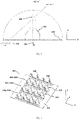
- Fig. 1 is a schematic diagram of a base station antenna 200' according to the prior art.
- Fig. 2 is a schematic diagram of equivalent active length of parasitic elements of the base station antenna of Fig. 1 at a small horizontal scanning angle and a large horizontal scanning angle, respectively.
- the base station antenna 200' may comprise a reflector 210' and a plurality of columns 220' of radiating elements 222'.
- the radiating elements 222' are mounted to extend forwardly of the reflector 210'.
- Radiating elements 222' may be configured as +/-45° cross dipole radiating elements as shown in Fig. 1 .
- Such radiating elements 222' basically have equal horizontal radiation component and vertical radiation component at small horizontal scanning angles AZ, for example, a horizontal scanning angle AZ of 0°. In other words, it basically has balanced horizontal and vertical radiation components. Therefore, the base station antenna 200' has good cross-polarization performance parameters, for example, cross-polar discrimination, at small horizontal scanning angles AZ.
- the base station antenna 200 has poorer cross-polarization performance parameters, for example, cross-polar discrimination, at a large horizontal scanning angle AZ.
- the base station antenna 200' In order to balance the radiation components of radiating elements 222' at a large horizontal scanning angle AZ and thereby improve the cross-polarization performance parameters, the base station antenna 200', as shown in Fig. 1 , includes metallic rod-shaped parasitic elements 230' that extend in a vertical direction V that are installed around the radiating elements 222'. Such metallic rod-shaped parasitic elements may also be referred to herein as parasitic pins.
- the first equivalent active length L1 may be understood as the length of a first projection 231 of the parasitic element 230' at a large horizontal scanning angle AZ on a base level (for example, the reflector).
- parasitic element 230' is provided with a second equivalent active length L2 in the vertical direction V.
- the parasitic element 230' is capable of changing the radiation components of the radiating element 222 at a large horizontal scanning angle AZ to make the radiation components of the radiating element 222 more balanced, thereby improving the cross-polarization performance parameters of the base station antenna 200' at a large horizontal scanning angle AZ.
- the parasitic element 230' also changes the radiation components of the radiating element 222' with basically the same method.
- This causes originally balanced radiation components of the radiating element 222' at small horizontal scanning angles AZ to possibly be imbalanced and may cause the originally good cross-polar discrimination of the base station antenna 200' at small horizontal scanning angles AZ to become worse.
- such base station antenna 200' is unable to obtain good cross-polar discrimination at both a large horizontal scanning angle AZ and a small horizontal scanning angle AZ.
- the present disclosure provides a new base station antenna 200.
- a plurality of parasitic elements 240 are installed in the base station antenna 200 of the present disclosure and the parasitic elements may be configured as rod-shaped metal parts or elongated metal parts.
- the parasitic elements may comprise a rod-shaped metal body or an elongated metal body.
- "rod-shaped", or “elongated” should be understood as a dimension on a longitudinal axis of the rod-shaped metal part or rod-shaped metal body being larger, for example, 5 times or even 10 times larger than its transverse dimension, for example, transverse diameter.
- the longitudinal axis of the rod-shaped metal part or longitudinal axis of the rod-shaped metal body basically extends in a forward direction Z perpendicular to a plane defined by the reflector 210.
- the cross-polarization performance parameters for example, cross-polar discrimination
- the originally good cross-polarization performance parameters of the base station antenna 200 at a small horizontal scanning angle AZ may also be maintained. This shall be described below in further detail with reference to Fig. 3 to Fig. 5 .
- Fig. 3 is a schematic diagram of a base station antenna according to some embodiments of the present disclosure.
- Fig. 4 is a schematic side view of the base station antenna in Fig. 3 .
- Fig. 5 is a schematic diagram of equivalent active lengths of a parasitic element of a base station antenna according to some embodiments of the present disclosure at a small horizontal scanning angle and a large horizontal scanning angle, respectively.
- the base station antenna 200 in the various embodiments of the present disclosure may be a beamforming antenna.
- the base station antenna 200 may comprise a reflector 210 and an array that comprises a plurality of columns 220 of radiating elements 222.
- the reflector 210 may be used as a ground plane for the radiating elements 222.
- the radiating elements 222 are mounted to extend in a forward direction Z from the reflector 210.
- Each radiating element 222 may be a high-band radiating element, a mid-band radiating element, or a low-band radiating element.
- the low-band radiating element may be configured to operate, for example, in the 617 MHz to 960 MHz frequency range or one or more partial ranges thereof.
- the mid-band radiating element may be configured to operate, for example, in the 1427 MHz to 2690 MHz frequency range or one or more partial ranges thereof.
- the high-band radiating element may be configured to operate, for example, in the 3 GHz to 5 GHz frequency range or one or more partial ranges thereof.
- the base station antenna 200 may comprise a plurality of (three in this example) vertically extending radiating element 222 columns 220.
- a first radiating element column 2201 comprises a plurality of (four in this example) first radiating elements arranged in a vertical direction;
- a second radiating element column 2202 comprises a plurality of (four in this example) second radiating elements arranged in a vertical direction;
- a third radiating element column 2203 comprises a plurality of (four in this example) third radiating elements arranged in a vertical direction.
- the radiating elements 222 in the first radiating element column 2201, the second radiating element column 2202 and the third radiating element column 2203 define a plurality of pairs of horizontally aligned radiating elements 222.
- the antenna assembly 200 may comprise any number of vertically arranged radiating element 222 columns 220, and each radiating element 222 column 220 may comprise any number of vertically arranged radiating elements 222.
- Radiating elements 222 may be configured as +/-45° cross dipole radiating elements as shown in Fig. 3 , or configured as radiating elements with a rectangular or square contour, which are not shown.
- the base station antenna 200 of the present disclosure is provided with a plurality of parasitic elements 240.
- Each parasitic element 240 may be configured as a rod-shaped metal part, or comprise a rod-shaped metal body.
- the length L of the parasitic elements 240 along the longitudinal axis a of the parasitic element 240 may be set as a positive integer multiple of one-quarter of the corresponding center frequency wavelength of the operating frequency band of each radiating element 222.
- the pre-determined length of the rod-shaped metal part or rod-shaped metal body may extend in a forward direction from the end close to the reflector, where the pre-determined length may be within the wavelength range of 0.1 to 0.5, a wavelength range of 0.15 to 0.4, or close to a wavelength of 0.25.
- a length of each parasitic element is within a wavelength range of 0.1 to 0.5, a wavelength range of 0.15 to 0.4, or close to a wavelength of 0.25.
- the parasitic element 240 may extend further forward than the radiating element 222 from the reflector 210.
- the parasitic elements 240 are spaced apart from the reflector 210, so that the parasitic elements 240 are adjacent to respective radiating arms of the radiating elements 222.
- the parasitic elements 240 may be arranged around each radiating element 222.
- the parasitic elements 240 may be arranged in a horizontal direction H between adjacent radiating elements 222.
- the parasitic elements 240 may also be arranged at other locations in the base station antenna 200. For example, they may be arranged in a vertical direction V between adjacent radiating elements 222 and/or arranged around the outside of the radiating element 222 columns.
- the parasitic element 240 may be configured as a rod-shaped metal part, where the longitudinal axis a of the rod-shaped metal part basically extends perpendicularly to the plane defined by the reflector 210.
- “basically perpendicularly” may be understood as the longitudinal axis a of the parasitic element 240 extending at an angle of between 70 to 110° (90° in this example) against the plane defined by the reflector 210.
- the parasitic element 240 is provided with a third equivalent active length L3 in a vertical direction V.
- the parasitic elements 240 of the present disclosure are similarly capable of improving the cross-polarization performance parameters, for example, cross-polar discrimination, of the base station antenna 200 at a large horizontal scanning angle AZ.
- the parasitic elements 240 of the present disclosure are provided with a fourth equivalent active length L4 in a vertical direction V.
- the fourth equivalent active length L4 is shortened.
- the "point" may be understood as a cross-section of the parasitic element in Fig. 5 .
- the fourth equivalent active length L4 is very small (it can be understood to be approximately 0 in this example). Therefore, such parasitic element 240 has very limited effects, and almost no effect, on the radiation components of the radiating element 222 at a small horizontal scanning angle AZ. Therefore, different from parasitic elements 230' in the prior art, the parasitic elements 240 of the present disclosure are capable of better maintaining the originally balanced radiation components of radiating elements 222 at a small horizontal scanning angle AZ, thereby maintaining originally good cross-polarization performance parameters, for example, cross-polar discrimination. Therefore, the base station antenna 200 of the present disclosure is capable of achieving good cross-polarization performance parameters at a large horizontal scanning angle AZ and also at a small horizontal scanning angle AZ.
- the longitudinal axis a of parasitic elements 240 may extend at an inclination angle against the plane defined by the reflector 210.
- the inclined angle for example, may be a range of angles from 70 to 110°, but this should not be understood as limiting the present disclosure.
- parasitic elements 240 may be provided with a fifth equivalent active length.
- the fifth equivalent active length may be between the second equivalent active length L2 and fourth equivalent active length L4, and may be changed by adjusting the above inclination angle according to actual needs.
- the parasitic elements 240 of the present disclosure are capable of targetedly changing the radiation components of radiating elements 222 at a small horizontal scanning angle AZ according to actual needs, thereby improving the cross-polarization performance parameters of radiating elements 222 at a small horizontal scanning angle AZ.
- the parasitic elements 240 may also be configured as a L-shaped or T-shaped purely metallic components which comprise a rod-shaped metal body and a connecting section basically perpendicularly connected to the rod-shaped metal body, and the connecting section may be indirectly connected to the reflector by means of a dielectric element.
- the connecting section may be provided with a sixth equivalent active length at a small horizontal scanning angle AZ. The sixth equivalent active length may be adjusted by changing the length of the connecting section according to actual needs.
- the L-shaped or T-shaped parasitic elements 240 are similarly capable of targetedly changing the radiation components of radiating elements 222 at a small horizontal scanning angle AZ, and are capable of improving the cross-polarization performance parameters of radiating elements 222 at a small horizontal scanning angle AZ.
- the parasitic elements 240 are positioned in front of the reflector 210 and are electrically floating with respect to the reflector.
- electrical suspension may be understood as “having no galvanic connection between the parasitic elements 240 and reflector”.
- the parasitic elements 240 basically act as a separate electric field component, making the current distribution of the parasitic elements 240 purer.
- the parasitic elements 240 may be arranged to be spaced apart from the reflector 210.
- the parasitic elements 240 may be fixed onto the reflector 210 with a dielectric element, thereby preventing galvanic connection between the parasitic elements 240 and the reflector 210.
- the parasitic elements 240 are configured as separate rod-shaped metal parts, the end of the rod-shaped metal parts facing the reflector may be indirectly connected to the reflector 210 with a dielectric element.
- the connecting section of the L-shaped or T-shaped purely metallic components may be indirectly connected to the reflector 210 with a dielectric element.
- the dielectric element may be connected to the parasitic elements 240 and reflector 210 through various suitable connection methods, for example, bonding, plugging, snap-fitting, soldering, or rivet connection.
- the dielectric element may also be configured as a plug-in medium in a slot housed on the reflector 210, and the parasitic elements 240 may be directly shape-fitted to and plugged into the medium.
- Fig. 6 is a schematic perspective view of a base station antenna 201 according to some embodiments of the present disclosure.
- a plurality of vertically extending fence elements 250 may be additionally mounted onto the reflector 210.
- Each fence element 250 may be a metallic element extending in a forward direction from the reflector 210 and mounted on the reflector 210.
- Arranging fence elements 250 around the radiating elements 222 can reduce the coupling interference of corresponding radiating elements 222, thereby further improving the radiation pattern of the base station antenna 200 and further improving the cross-polarization performance parameters of the base station antenna 200.
- the antenna assembly 200 may further comprise a plurality of fence elements 250 extending in a horizontal direction H and the fence elements 250 are respectively arranged in a vertical direction between adjacent radiating elements 222.
- the parasitic elements 240' in order to mount the parasitic elements 240' in front of the reflector 210 so that they are electrically floating with respect to the reflector, the parasitic elements 240' may be mounted on the fence elements 250 with a dielectric element, for example, a PCB substrate, and indirectly fixed onto the reflector 210.
- the PCB substrate may be fixed on the fence elements 250 by, for example, a rivet connection.
- the PCB substrate in Fig. 6 is not fixed onto the fence elements 250 but directly mounted on the reflector and extends in a forward direction from the reflector.
- the PCB substrate may be plugged into the corresponding groove of the reflector 210.
- the PCB substrate may also be mounted on a L-shaped plastic contact pin and indirectly fixed on the reflector 210.
- the parasitic elements 240' may be printed on the PCB substrate as printed traces, for example, on a first main surface and/or a second main surface of the PCB substrate.
- Printed traces acting as parasitic elements may be centrally printed on the PCB substrate and extend forwards a pre-determined length, for example, one quarter of a wavelength of corresponding to the center frequency of the operating frequency band of the radiating elements 222, from the end close to the reflector.
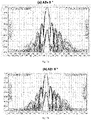
- Figs. 7a-7d show radiation patterns of a base station antenna 200 before and after installing parasitic elements 240 at horizontal scanning angles AZ of 6° and 47°, in which, Fig. 7a shows a radiation pattern of the base station antenna 200 before installing parasitic elements 240 at a horizontal scanning angle AZ of 6°; Fig. 7b shows a radiation pattern of the base station antenna 200 after installing parasitic elements 240 at a horizontal scanning angle AZ of 6°; Fig. 7c shows a radiation pattern of the base station antenna 200 before installing parasitic elements 240 at a horizontal scanning angle AZ of 47°; Fig. 7d shows a radiation pattern of the base station antenna 200 after installing parasitic elements 240 at a horizontal scanning angle AZ of 47°.
- the base station antenna 200 according to the present disclosure can bring one or more of the following advantages: first, the base station antenna 200 according to the present disclosure is capable of improving cross-polarization performance parameters, for example, cross-polar discrimination, at a large horizontal scanning angle AZ and is capable of maintaining originally good cross-polarization performance parameters, for example, cross-polar discrimination, at a small horizontal scanning angle AZ relatively as well; second, the parasitic elements 240 are positioned in front of the reflector so as to be electrically floating with respect to the reflector, and hence have almost no effect on the current distribution on the reflector or are hardly affected by the reflector; third, the parasitic elements 240 are capable of targetedly changing the radiation components of radiating elements 222 at a small horizontal scanning angle AZ according to actual needs, thereby improving the cross-polarization performance parameters of radiating elements 222 at a small horizontal scanning angle AZ.
Landscapes
- Engineering & Computer Science (AREA)
- Computer Networks & Wireless Communication (AREA)
- Physics & Mathematics (AREA)
- Electromagnetism (AREA)
- Aerials With Secondary Devices (AREA)
- Variable-Direction Aerials And Aerial Arrays (AREA)
Abstract
Description
- The present application claims priority to
Chinese Patent Application No. 202110823743.9, filed July 21, 2021 - The present disclosure generally relates to radio communications and more particularly, to base station antennas for cellular communications systems.
- An array that includes a plurality of closely spaced radiating element columns, for example, columns of +/-45° cross dipole radiating elements that are configured for beamforming, are mounted in some base station antennas such as beamforming base station antennas. Such arrays tend to have good cross-polarization performance parameters, for example, cross-polar discrimination, at small horizontal (i.e., azimuth plane) scanning angles, for example, a horizontal scanning angle close to 0°, but have poorer cross-polarization performance parameters at larger horizontal scanning angles, for example, a horizontal scanning angle close to 47°.
- In order to improve cross-polarization performance parameters of the base station antenna at large horizontal scanning angles, in a solution of the prior art as shown in
Fig. 1 , parasitic elements 230' extending in a vertical direction V are usually used. Herein, a horizontal direction H corresponds to a row direction of the radiating elements in the array and the vertical direction V corresponds to the column direction of the radiating elements in the array. If the base station antenna is mounted for use without any downtilt in the elevation plane, the horizontal direction will be parallel to a plane defined by the horizon and the vertical direction will intersect the plane defined by the horizon at a right angle. - According to a first aspect of the present disclosure, a base station antenna is provided; the base station antenna comprises: a reflector; a plurality of first radiating elements arranged in a first column that extends in a vertical direction, where the first radiating elements extend in a forward direction from the reflector; a plurality of second radiating element arranged in a second column that extends in the vertical direction, where the second radiating elements extend in the forward direction from the reflector; and a plurality of parasitic elements, where the parasitic elements are arranged around the first radiating elements and/or second radiating elements; wherein, each parasitic element is configured as a rod-shaped metal part or comprises a rod-shaped metal body, where a longitudinal axis of the rod-shaped metal part or a longitudinal axis of the rod-shaped metal body extends at an angle of between 70° to 110° with respect to a plane defined by the reflector, and the parasitic elements are positioned in front of the reflector in and are electrically floating with respect to the reflector.
- In some embodiments, the longitudinal axis of the rod-shaped metal part or the longitudinal axis of the rod-shaped metal body basically extends perpendicularly to a plane defined by the reflector.
- According to a second aspect of the present disclosure, a base station antenna is provided; the base station antenna comprises: a reflector; a plurality of first radiating elements arranged in a first column extending in a vertical direction, where the first radiating elements extend in a forward direction from the reflector; a plurality of second radiating elements arranged in a second column extending in the vertical direction, where the second radiating elements extend in the forward direction from the reflector and the first and second radiating elements in the first column and the second column define a plurality of pairs of horizontally aligned radiating elements; and a plurality of parasitic elements, where each parasitic element is positioned between a respective one of the pairs of horizontally-aligned radiating elements, wherein, each parasitic element is configured as a rod-shaped metal part or comprises a rod-shaped metal body, where a longitudinal axis of the rod-shaped metal part or a longitudinal axis of the rod-shaped metal body extends at an angle of between 70° to 110° with respect to a plane defined by the reflector; and wherein, the parasitic elements are positioned to improve peak cross-polar discrimination by at least 2 dB at a horizontal scanning angle larger than a first angle without having peak cross-polar discrimination worsen by more than 1 dB at a horizontal scanning angle smaller than a second angle.
- The base station antenna according to some embodiments of the present disclosure is capable of improving cross-polarization performance parameters, for example, cross-polar discrimination, at a large horizontal scanning angle and is capable of maintaining originally good cross-polarization performance parameters at a small horizontal scanning angle, or is capable of targetedly improving cross-polar discrimination at a small horizontal scanning angle. In addition, locating parasitic elements of the base station antenna in front of the reflector in a form of being electrically floated with the reflector according to some embodiments of the present disclosure has limited effects on current distribution of the base station antenna.
-
-
Fig. 1 is a schematic diagram of a base station antenna according to the prior art, where parasitic elements extending in a vertical direction V are mounted forwardly of the reflector of the base station antenna. -
Fig. 2 is a schematic diagram of equivalent active length of parasitic elements of the base station antenna inFig. 1 at a small horizontal scanning angle and a large horizontal scanning angle, respectively. -
Fig. 3 is a schematic diagram of a base station antenna according to some embodiments of the present disclosure, where parasitic elements extending in a forward direction Z are mounted forwardly of the reflector of the base station antenna. -
Fig. 4 is a schematic side view of the base station antenna inFig. 3 . -
Fig. 5 is a schematic diagram of equivalent active length of parasitic elements of a base station antenna according to some embodiments of the present disclosure at a small horizontal scanning angle and a large horizontal scanning angle, respectively. -
Fig. 6 is a schematic diagram of a base station antenna according to some embodiments of the present disclosure, where fence elements extending in a vertical direction V are mounted on the base station antenna and parasitic elements extending in a forward direction Z are mounted on the fence elements. -
Figs. 7a-7d are a series of graphs depicting azimuth plane radiation patterns of a base station antenna before and after installing parasitic elements at horizontal scanning angles of 6° and 47°. -
Fig. 1 is a schematic diagram of a base station antenna 200' according to the prior art.Fig. 2 is a schematic diagram of equivalent active length of parasitic elements of the base station antenna ofFig. 1 at a small horizontal scanning angle and a large horizontal scanning angle, respectively. - As shown in
Fig. 1 , the base station antenna 200' may comprise a reflector 210' and a plurality of columns 220' of radiating elements 222'. The radiating elements 222' are mounted to extend forwardly of the reflector 210'. Radiating elements 222', for example, may be configured as +/-45° cross dipole radiating elements as shown inFig. 1 . Such radiating elements 222' basically have equal horizontal radiation component and vertical radiation component at small horizontal scanning angles AZ, for example, a horizontal scanning angle AZ of 0°. In other words, it basically has balanced horizontal and vertical radiation components. Therefore, the base station antenna 200' has good cross-polarization performance parameters, for example, cross-polar discrimination, at small horizontal scanning angles AZ. However, at large horizontal scanning angles AZ, for example, a horizontal scanning angle AZ of 47°, the horizontal and vertical radiation components of radiating elements 222' may change and may no longer be balanced. Therefore, as compared to a small horizontal scanning angle AZ, thebase station antenna 200 has poorer cross-polarization performance parameters, for example, cross-polar discrimination, at a large horizontal scanning angle AZ. - In order to balance the radiation components of radiating elements 222' at a large horizontal scanning angle AZ and thereby improve the cross-polarization performance parameters, the base station antenna 200', as shown in
Fig. 1 , includes metallic rod-shaped parasitic elements 230' that extend in a vertical direction V that are installed around the radiating elements 222'. Such metallic rod-shaped parasitic elements may also be referred to herein as parasitic pins. The working principle of parasitic elements 230' is described in further detail with reference toFig. 2 . As shown inFig. 2 , at a large horizontal scanning angle AZ (AZ = 47° in this example), the parasitic element 230' has a first equivalent active length L1 in a vertical direction. The first equivalent active length L1 may be understood as the length of afirst projection 231 of the parasitic element 230' at a large horizontal scanning angle AZ on a base level (for example, the reflector). Similarly, at a small horizontal scanning angle AZ (AZ = 0° in this example), parasitic element 230' is provided with a second equivalent active length L2 in the vertical direction V. The parasitic element 230' is capable of changing the radiation components of theradiating element 222 at a large horizontal scanning angle AZ to make the radiation components of theradiating element 222 more balanced, thereby improving the cross-polarization performance parameters of the base station antenna 200' at a large horizontal scanning angle AZ. However, at a small horizontal scanning angle AZ, based on its first equivalent active length L1, the parasitic element 230' also changes the radiation components of the radiating element 222' with basically the same method. This causes originally balanced radiation components of the radiating element 222' at small horizontal scanning angles AZ to possibly be imbalanced and may cause the originally good cross-polar discrimination of the base station antenna 200' at small horizontal scanning angles AZ to become worse. In other words, such base station antenna 200' is unable to obtain good cross-polar discrimination at both a large horizontal scanning angle AZ and a small horizontal scanning angle AZ. - In order to overcome the above drawback in the prior art, the present disclosure provides a new
base station antenna 200. A plurality ofparasitic elements 240 are installed in thebase station antenna 200 of the present disclosure and the parasitic elements may be configured as rod-shaped metal parts or elongated metal parts. Alternatively, the parasitic elements may comprise a rod-shaped metal body or an elongated metal body. In the present disclosure, "rod-shaped", or "elongated" should be understood as a dimension on a longitudinal axis of the rod-shaped metal part or rod-shaped metal body being larger, for example, 5 times or even 10 times larger than its transverse dimension, for example, transverse diameter. The longitudinal axis of the rod-shaped metal part or longitudinal axis of the rod-shaped metal body basically extends in a forward direction Z perpendicular to a plane defined by thereflector 210. - In this way, the cross-polarization performance parameters, for example, cross-polar discrimination, of the
base station antenna 200 at a large horizontal scanning angle AZ may be improved and the originally good cross-polarization performance parameters of thebase station antenna 200 at a small horizontal scanning angle AZ may also be maintained. This shall be described below in further detail with reference toFig. 3 to Fig. 5 . -
Fig. 3 is a schematic diagram of a base station antenna according to some embodiments of the present disclosure.Fig. 4 is a schematic side view of the base station antenna inFig. 3 .Fig. 5 is a schematic diagram of equivalent active lengths of a parasitic element of a base station antenna according to some embodiments of the present disclosure at a small horizontal scanning angle and a large horizontal scanning angle, respectively. - The base station antenna 200 in the various embodiments of the present disclosure, for example, may be a beamforming antenna. As shown in
Fig. 3 , thebase station antenna 200 may comprise areflector 210 and an array that comprises a plurality ofcolumns 220 ofradiating elements 222. Thereflector 210 may be used as a ground plane for theradiating elements 222. Theradiating elements 222 are mounted to extend in a forward direction Z from thereflector 210. Eachradiating element 222 may be a high-band radiating element, a mid-band radiating element, or a low-band radiating element. The low-band radiating element may be configured to operate, for example, in the 617 MHz to 960 MHz frequency range or one or more partial ranges thereof. The mid-band radiating element may be configured to operate, for example, in the 1427 MHz to 2690 MHz frequency range or one or more partial ranges thereof. The high-band radiating element may be configured to operate, for example, in the 3 GHz to 5 GHz frequency range or one or more partial ranges thereof. - In the embodiment of
Fig. 3 , thebase station antenna 200 may comprise a plurality of (three in this example) vertically extendingradiating element 222columns 220. A firstradiating element column 2201 comprises a plurality of (four in this example) first radiating elements arranged in a vertical direction; a secondradiating element column 2202 comprises a plurality of (four in this example) second radiating elements arranged in a vertical direction; a thirdradiating element column 2203 comprises a plurality of (four in this example) third radiating elements arranged in a vertical direction. The radiatingelements 222 in the firstradiating element column 2201, the secondradiating element column 2202 and the thirdradiating element column 2203 define a plurality of pairs of horizontally aligned radiatingelements 222. Here, it should be understood that theantenna assembly 200 may comprise any number of vertically arranged radiatingelement 222columns 220, and each radiatingelement 222column 220 may comprise any number of vertically arranged radiatingelements 222.Radiating elements 222, for example, may be configured as +/-45° cross dipole radiating elements as shown inFig. 3 , or configured as radiating elements with a rectangular or square contour, which are not shown. - As shown in
Fig. 3 , thebase station antenna 200 of the present disclosure is provided with a plurality ofparasitic elements 240. Eachparasitic element 240 may be configured as a rod-shaped metal part, or comprise a rod-shaped metal body. The length L of theparasitic elements 240 along the longitudinal axis a of theparasitic element 240, for example, may be set as a positive integer multiple of one-quarter of the corresponding center frequency wavelength of the operating frequency band of each radiatingelement 222. In other words, the pre-determined length of the rod-shaped metal part or rod-shaped metal body may extend in a forward direction from the end close to the reflector, where the pre-determined length may be within the wavelength range of 0.1 to 0.5, a wavelength range of 0.15 to 0.4, or close to a wavelength of 0.25. In other words, a length of each parasitic element is within a wavelength range of 0.1 to 0.5, a wavelength range of 0.15 to 0.4, or close to a wavelength of 0.25. In some embodiments, as shown inFig. 5 , theparasitic element 240 may extend further forward than the radiatingelement 222 from thereflector 210. In some embodiments, theparasitic elements 240 are spaced apart from thereflector 210, so that theparasitic elements 240 are adjacent to respective radiating arms of the radiatingelements 222. - Continuing to refer to
Fig. 3 , theparasitic elements 240 may be arranged around each radiatingelement 222. Theparasitic elements 240, for example, may be arranged in a horizontal direction H between adjacent radiatingelements 222. In some embodiments, theparasitic elements 240 may also be arranged at other locations in thebase station antenna 200. For example, they may be arranged in a vertical direction V between adjacent radiatingelements 222 and/or arranged around the outside of the radiatingelement 222 columns. - It can be clearly seen in
Fig. 5 that theparasitic element 240 may be configured as a rod-shaped metal part, where the longitudinal axis a of the rod-shaped metal part basically extends perpendicularly to the plane defined by thereflector 210. In the present disclosure, "basically perpendicularly" may be understood as the longitudinal axis a of theparasitic element 240 extending at an angle of between 70 to 110° (90° in this example) against the plane defined by thereflector 210. In this case, as shown inFig. 5 , at a large horizontal scanning angle AZ (AZ = 47° in this example), theparasitic element 240 is provided with a third equivalent active length L3 in a vertical direction V. Therefore, theparasitic elements 240 of the present disclosure are similarly capable of improving the cross-polarization performance parameters, for example, cross-polar discrimination, of thebase station antenna 200 at a large horizontal scanning angle AZ. However, at a small horizontal scanning angle AZ (AZ = 0°) in this example, theparasitic elements 240 of the present disclosure are provided with a fourth equivalent active length L4 in a vertical direction V. As compared to the actual length L of the parasitic elements, the fourth equivalent active length L4 is shortened. As shown inFig. 5 , when AZ = 0°, the fourth equivalent active length L4 is shortened to be a point. Here, the "point" may be understood as a cross-section of the parasitic element inFig. 5 . As compared to the length L or third equivalent active length L3 of the parasitic element, the fourth equivalent active length L4 is very small (it can be understood to be approximately 0 in this example). Therefore, suchparasitic element 240 has very limited effects, and almost no effect, on the radiation components of the radiatingelement 222 at a small horizontal scanning angle AZ. Therefore, different from parasitic elements 230' in the prior art, theparasitic elements 240 of the present disclosure are capable of better maintaining the originally balanced radiation components of radiatingelements 222 at a small horizontal scanning angle AZ, thereby maintaining originally good cross-polarization performance parameters, for example, cross-polar discrimination. Therefore, thebase station antenna 200 of the present disclosure is capable of achieving good cross-polarization performance parameters at a large horizontal scanning angle AZ and also at a small horizontal scanning angle AZ. - In some cases, for example, when radiating
elements 222 have slightly imbalanced radiation components at a small horizontal scanning angle AZ, in order to change and balance the radiation components of radiatingelements 222 at a small horizontal scanning angle AZ, the longitudinal axis a ofparasitic elements 240 may extend at an inclination angle against the plane defined by thereflector 210. The inclined angle, for example, may be a range of angles from 70 to 110°, but this should not be understood as limiting the present disclosure. In this case, at a small horizontal scanning angle AZ,parasitic elements 240 may be provided with a fifth equivalent active length. The fifth equivalent active length may be between the second equivalent active length L2 and fourth equivalent active length L4, and may be changed by adjusting the above inclination angle according to actual needs. In this way, theparasitic elements 240 of the present disclosure are capable of targetedly changing the radiation components of radiatingelements 222 at a small horizontal scanning angle AZ according to actual needs, thereby improving the cross-polarization performance parameters of radiatingelements 222 at a small horizontal scanning angle AZ. - In some alternative embodiments, the
parasitic elements 240 may also be configured as a L-shaped or T-shaped purely metallic components which comprise a rod-shaped metal body and a connecting section basically perpendicularly connected to the rod-shaped metal body, and the connecting section may be indirectly connected to the reflector by means of a dielectric element. The connecting section may be provided with a sixth equivalent active length at a small horizontal scanning angle AZ. The sixth equivalent active length may be adjusted by changing the length of the connecting section according to actual needs. Therefore, the L-shaped or T-shapedparasitic elements 240 are similarly capable of targetedly changing the radiation components of radiatingelements 222 at a small horizontal scanning angle AZ, and are capable of improving the cross-polarization performance parameters of radiatingelements 222 at a small horizontal scanning angle AZ. - In addition, to minimize the effects of current distribution on the reflector, the
parasitic elements 240 are positioned in front of thereflector 210 and are electrically floating with respect to the reflector. In the present disclosure, "electrical suspension" may be understood as "having no galvanic connection between theparasitic elements 240 and reflector". As such, theparasitic elements 240 basically act as a separate electric field component, making the current distribution of theparasitic elements 240 purer. - In order to mount the
parasitic elements 240 in front of thereflector 210 in a form of being electrically floating with respect to the reflector. As shown inFig. 4 , theparasitic elements 240 may be arranged to be spaced apart from thereflector 210. For this purpose, theparasitic elements 240 may be fixed onto thereflector 210 with a dielectric element, thereby preventing galvanic connection between theparasitic elements 240 and thereflector 210. When theparasitic elements 240 are configured as separate rod-shaped metal parts, the end of the rod-shaped metal parts facing the reflector may be indirectly connected to thereflector 210 with a dielectric element. When theparasitic elements 240 are configured as L-shaped or T-shaped purely metallic components as described above, the connecting section of the L-shaped or T-shaped purely metallic components may be indirectly connected to thereflector 210 with a dielectric element. The dielectric element may be connected to theparasitic elements 240 andreflector 210 through various suitable connection methods, for example, bonding, plugging, snap-fitting, soldering, or rivet connection. In addition, the dielectric element may also be configured as a plug-in medium in a slot housed on thereflector 210, and theparasitic elements 240 may be directly shape-fitted to and plugged into the medium. -
Fig. 6 is a schematic perspective view of a base station antenna 201 according to some embodiments of the present disclosure. In order to reduce coupling interference between adjacent radiatingelements 222, in some embodiments of the present disclosure, apart from parasitic elements 240', a plurality of vertically extending fence elements 250 may be additionally mounted onto thereflector 210. Each fence element 250 may be a metallic element extending in a forward direction from thereflector 210 and mounted on thereflector 210. Arranging fence elements 250 around the radiatingelements 222 can reduce the coupling interference of corresponding radiatingelements 222, thereby further improving the radiation pattern of thebase station antenna 200 and further improving the cross-polarization performance parameters of thebase station antenna 200. The fence elements 250 shown inFig. 6 are arranged in a horizontal direction H between adjacent radiatingelements 222. It should be understood that the number and arrangement of the fence elements 250 may also be changed according to actual needs. For example, theantenna assembly 200 may further comprise a plurality of fence elements 250 extending in a horizontal direction H and the fence elements 250 are respectively arranged in a vertical direction between adjacent radiatingelements 222. - In the embodiment shown in
Fig. 6 , in order to mount the parasitic elements 240' in front of thereflector 210 so that they are electrically floating with respect to the reflector, the parasitic elements 240' may be mounted on the fence elements 250 with a dielectric element, for example, a PCB substrate, and indirectly fixed onto thereflector 210. The PCB substrate may be fixed on the fence elements 250 by, for example, a rivet connection. However, it may be conceived that the PCB substrate inFig. 6 is not fixed onto the fence elements 250 but directly mounted on the reflector and extends in a forward direction from the reflector. Here, the PCB substrate may be plugged into the corresponding groove of thereflector 210. In addition, the PCB substrate may also be mounted on a L-shaped plastic contact pin and indirectly fixed on thereflector 210. - In the embodiment in
Fig. 6 , the parasitic elements 240' may be printed on the PCB substrate as printed traces, for example, on a first main surface and/or a second main surface of the PCB substrate. Printed traces acting as parasitic elements may be centrally printed on the PCB substrate and extend forwards a pre-determined length, for example, one quarter of a wavelength of corresponding to the center frequency of the operating frequency band of the radiatingelements 222, from the end close to the reflector. -
Figs. 7a-7d show radiation patterns of abase station antenna 200 before and after installingparasitic elements 240 at horizontal scanning angles AZ of 6° and 47°, in which,Fig. 7a shows a radiation pattern of thebase station antenna 200 before installingparasitic elements 240 at a horizontal scanning angle AZ of 6°;Fig. 7b shows a radiation pattern of thebase station antenna 200 after installingparasitic elements 240 at a horizontal scanning angle AZ of 6°;Fig. 7c shows a radiation pattern of thebase station antenna 200 before installingparasitic elements 240 at a horizontal scanning angle AZ of 47°;Fig. 7d shows a radiation pattern of thebase station antenna 200 after installingparasitic elements 240 at a horizontal scanning angle AZ of 47°. It can be clearly seen fromFigs. 7a-7d that thebase station antenna 200 according to the present disclosure is capable of improving the peak cross-polar discrimination at a large horizontal scanning angle AZ (AZ = 47° in this example) by at least 2 dB (3 dB in this example) without causing the peak cross-polar discrimination at a small horizontal scanning angle AZ (AZ = 6°) to drop by more than 1 dB (this is basically unchanged in this example). Therefore, it can be seen that thebase station antenna 200 according to the present disclosure is capable of improving cross-polar discrimination at a large horizontal scanning angle AZ and is also capable of maintaining originally good cross-polar discrimination at a small horizontal scanning angle AZ. - The
base station antenna 200 according to the present disclosure can bring one or more of the following advantages: first, thebase station antenna 200 according to the present disclosure is capable of improving cross-polarization performance parameters, for example, cross-polar discrimination, at a large horizontal scanning angle AZ and is capable of maintaining originally good cross-polarization performance parameters, for example, cross-polar discrimination, at a small horizontal scanning angle AZ relatively as well; second, theparasitic elements 240 are positioned in front of the reflector so as to be electrically floating with respect to the reflector, and hence have almost no effect on the current distribution on the reflector or are hardly affected by the reflector; third, theparasitic elements 240 are capable of targetedly changing the radiation components of radiatingelements 222 at a small horizontal scanning angle AZ according to actual needs, thereby improving the cross-polarization performance parameters of radiatingelements 222 at a small horizontal scanning angle AZ. - Although exemplary embodiments of the present disclosure have been described, those skilled in the art should understand that many variations and modifications are possible in the exemplary embodiments without materially departing from the spirit and scope of the present disclosure. Therefore, all variations and changes are included in the protection scope of the present disclosure defined by the claims. The present disclosure is defined by the attached claims, and equivalents of these claims are also included.
- Further aspects of the disclosure may be summarised as follows:
- 1. A base station antenna, comprising:
- a reflector;
- a plurality of first radiating elements arranged in a first column that extends in a vertical direction, where the first radiating elements extend in a forward direction from the reflector;
- a plurality of second radiating element arranged in a second column that extends in the vertical direction, where the second radiating elements extend in the forward direction from the reflector; and
- a plurality of parasitic elements, where the parasitic elements are arranged around the first radiating elements and/or second radiating elements;
- wherein, each parasitic element is configured as a rod-shaped metal part or comprises a rod-shaped metal body, where a longitudinal axis of the rod-shaped metal part or a longitudinal axis of the rod-shaped metal body extends at an angle of between 70 to 110° with respect to a plane defined by the reflector, and the parasitic elements are positioned in front of the reflector in and are electrically floating with respect to the reflector.
- 2. The base station antenna according to Aspect 1, wherein, the parasitic elements are spaced apart from the reflector.
- 3. The base station antenna according to Aspect 1 or 2, wherein, at least some of the parasitic elements are arranged between respective pairs of horizontally adjacent first radiating elements and second radiating elements.
- 4. The base station antenna according to any one of the preceding Aspects, in particular Aspect 1 or 2, wherein at least some of the parasitic elements are fixed onto the reflector by respective dielectric elements.
- 5. The base station antenna according to any one of the preceding Aspects, in particular Aspect 4, wherein, the dielectric elements are printed circuit board ("PCB") substrates and the parasitic elements are printed on the respective printed circuit board ("PCB") substrate as respective printed traces.
- 6. The base station antenna according to any one of the preceding Aspects, in particular Aspect 5, wherein, the printed traces are centrally printed on the respective printed circuit board ("PCB") substrates in a forward direction.
- 7. The base station antenna according to any one of the preceding Aspects, in particular Aspect 5, wherein, the printed circuit board ("PCB") substrate is directly mounted on the reflector and extends in a forward direction from the reflector.
- 8. The base station antenna according to any one of the preceding Aspects, in particular Aspect 1 or 2, wherein, the base station antenna comprises a plurality of fence elements extending in a vertical direction, where the fence elements extend in a forward direction from the reflector and are mounted on the reflector, wherein, the fence elements are arranged around the first radiating elements and/or the second radiating elements.
- 9. The base station antenna according to any one of the preceding Aspects, in particular Aspect 8, wherein, the fence elements are arranged between horizontally adjacent first radiating elements and second radiating elements.
- 10. The base station antenna according to Aspect 8, wherein, the parasitic elements are mounted on respective ones of the fence elements with a dielectric element and indirectly fixed on the reflector.
- 11. The base station antenna according to any one of the preceding Aspects, in particular Aspect 1 or 2, wherein, the parasitic elements extend further forward from the reflector than the first radiating elements and second radiating elements.
- 12. The base station antenna according to any one of the preceding Aspects, in particular Aspect 1 or 2, wherein, a length of each parasitic element is within a wavelength range of 0.1 to 0.5, and the wavelength is a wavelength corresponding to a center frequency wavelength of an operating frequency band of the first radiating elements or the second radiating elements.
- 13. The base station antenna according to any one of the preceding Aspects, in particular Aspect 12, wherein, the length of each parasitic element is within a wavelength range of 0.15 to 0.4.
- 14. The base station antenna according to any one of the preceding Aspects, in particular Aspect 12, wherein, the length of each parasitic element is a wavelength of 0.25.
- 15. The base station antenna according to any one of the preceding Aspects, in particular Aspect 1 or 2, wherein, the parasitic elements are configured as separate rod-shaped metal parts and the end of the rod-shaped metal parts facing the reflector are indirectly connected to the reflector by means of a dielectric element.
- 16. The base station antenna according to any one of the preceding Aspects, in particular Aspect 1 or 2, wherein, the parasitic elements further comprise a connecting section vertically connected to the rod-shaped metal body and the connecting section is indirectly connected to the reflector by means of a dielectric element.
- 17. The base station antenna according to any one of the preceding Aspects, in particular Aspect 1 or 2, wherein, the parasitic elements comprise copper or aluminum.
- 18. The base station antenna according to any one of the preceding Aspects, in particular Aspect 2, wherein, the parasitic elements are spaced apart from the reflector, so that the parasitic elements are adjacent to respective radiating arms of the first radiating elements and the second radiating elements.
- 19. A base station antenna, comprising:
- a reflector;
- a plurality of first radiating elements arranged in a first column extending in a vertical direction, where the first radiating elements extend in a forward direction from the reflector;
- a plurality of second radiating elements arranged in a second column extending in the vertical direction, where the second radiating elements extend in the forward direction from the reflector and the first and second radiating elements in the first column and the second column define a plurality of pairs of horizontally aligned radiating elements; and
- a plurality of parasitic elements, where each parasitic element is positioned between a respective one of the pairs of horizontally-aligned radiating elements,
- wherein, each parasitic element is configured as a rod-shaped metal part or comprises a rod-shaped metal body, where a longitudinal axis of the rod-shaped metal part or a longitudinal axis of the rod-shaped metal body extends at an angle of between 70 to 110° with respect to a plane defined by the reflector; and
- wherein, the parasitic elements are positioned to improve peak cross-polar discrimination by at least 2 dB at a horizontal scanning angle larger than a first angle without having peak cross-polar discrimination worsen by more than 1 dB at a horizontal scanning angle smaller than a second angle.
- 20. The base station antenna according to any one of the preceding Aspects, in particular Aspect 19, wherein, at a horizontal scanning angle larger than the first angle, the peak cross-polar discrimination is improved by at least 3 dB.
- 21. The base station antenna according to any one of the preceding Aspects, in
particular Aspect 19 or 20, wherein, at a horizontal scanning angle smaller than the second angle, the peak cross-polar discrimination is basically unchanged. - 22. The base station antenna according to any one of the preceding Aspects, in
particular Aspect 19 or 20, wherein, the first angle is between 41°-53° and the second angle is between 0°-12°. - 23. The base station antenna according to any one of the preceding Aspects, in
particular Aspect 19 or 20, wherein, the longitudinal axis of the rod-shaped metal part or the longitudinal axis of the rod-shaped metal body extends perpendicularly to the plane defined by the reflector. - 24. The base station antenna according to any one of the preceding Aspects, in
particular Aspect 19 or 20, wherein, at the horizontal scanning angle of the second angle, the equivalent active length of the parasitic elements in a vertical direction is shortened as compared to the actual length of the parasitic elements. - 25. The base station antenna according to any one of the preceding Aspects, in
particular Aspect 19 or 20, wherein, when the second angle is 0°, the equivalent active length of the parasitic elements is shortened to be a point.
Claims (15)
- A base station antenna, comprising:a reflector;a plurality of first radiating elements arranged in a first column that extends in a vertical direction, where the first radiating elements extend in a forward direction from the reflector;a plurality of second radiating element arranged in a second column that extends in the vertical direction, where the second radiating elements extend in the forward direction from the reflector; anda plurality of parasitic elements, where the parasitic elements are arranged around the first radiating elements and/or the second radiating elements;wherein each parasitic element comprises a rod-shaped metal part, where a longitudinal axis of the rod-shaped metal part extends at an angle of between 70° to 110° with respect to a plane defined by the reflector, and the parasitic elements are positioned in front of the reflector and are electrically floating with respect to the reflector.
- The base station antenna according to Claim 1, wherein the parasitic elements are spaced apart from the reflector.
- The base station antenna according to Claim 1 or 2, wherein at least some of the parasitic elements are arranged between respective pairs of horizontally adjacent first radiating elements and second radiating elements.
- The base station antenna according to Claim 1 to 3, wherein at least some of the parasitic elements are fixed onto the reflector by respective dielectric elements, wherein the dielectric elements are preferably printed circuit board, PCB, substrates and the parasitic elements are printed on the respective PCB substrate as respective printed traces, wherein further preferably the printed traces are printed on the respective PCB substrates in a forward direction and/or the PCB substrates are directly mounted on the reflector and extend in a forward direction from the reflector.
- The base station antenna according to any one of Claims 1 to 4, further comprising a plurality of fence elements extending in a vertical direction, where the fence elements extend in a forward direction from the reflector and are mounted on the reflector, the fence elements are arranged around the first radiating elements and/or the second radiating elements, wherein the fence elements are preferably arranged between horizontally adjacent first radiating elements and second radiating elements, and/or the parasitic elements are preferably mounted on respective ones of the fence elements with a dielectric element and indirectly fixed on the reflector.
- The base station antenna according to any one of Claims 1 to 5, wherein the parasitic elements extend further forward from the reflector than the first radiating elements and second radiating elements.
- The base station antenna according to any one of Claims 1 to 6, wherein a length of each parasitic element is within a wavelength range of 0.1 to 0.5, and the wavelength is a wavelength corresponding to a center frequency wavelength of an operating frequency band of the first radiating elements or the second radiating elements, wherein the length of each parasitic element is preferably within a wavelength range of 0.15 to 0.4, wherein the length of each parasitic element is further preferably a wavelength of 0.25.
- The base station antenna according to any one of Claims 1 to 7, wherein the parasitic elements are configured as separate rod-shaped metal parts and the ends of the respective rod-shaped metal parts that face the reflector are indirectly connected to the reflector by means of one or more dielectric elements.
- The base station antenna according to any one of Claims 1 to 8, wherein the parasitic elements further comprise a connecting section vertically connected to the rod-shaped metal body and the connecting section is indirectly connected to the reflector by means of a dielectric element.
- The base station antenna according to any one of Claims 1 to 9, wherein the parasitic elements are spaced apart from the reflector, so that the parasitic elements are adjacent to respective radiating arms of the first radiating elements and the second radiating elements.
- A base station antenna, comprising:a reflector;a plurality of first radiating elements arranged in a first column extending in a vertical direction, where the first radiating elements extend in a forward direction from the reflector;a plurality of second radiating elements arranged in a second column extending in the vertical direction, where the second radiating elements extend in the forward direction from the reflector and the first and second radiating elements in the first column and the second column define a plurality of pairs of horizontally aligned radiating elements; anda plurality of parasitic elements, where each parasitic element is positioned between a respective one of the pairs of horizontally-aligned radiating elements,wherein each parasitic element is configured as a rod-shaped metal part, andwherein, the parasitic elements are positioned to improve peak cross-polar discrimination by at least 2 dB at a horizontal scanning angle larger than a first angle without having peak cross-polar discrimination worsen by more than 1 dB at a horizontal scanning angle smaller than a second angle,wherein the first angle is between 41°-53° and the second angle is between 0°-12°.
- The base station antenna according to Claim 11, wherein at a horizontal scanning angle larger than the first angle, the peak cross-polar discrimination is improved by at least 3 dB.
- The base station antenna according to Claim 11 or 12, wherein at a horizontal scanning angle smaller than the second angle, the peak cross-polar discrimination is substantially unchanged, and/or at the horizontal scanning angle of the second angle, the equivalent active length of the parasitic elements in a vertical direction is shortened as compared to the actual length of the parasitic elements..
- The base station antenna according to any one of Claims 11 to 13, wherein a longitudinal axis of the rod-shaped metal part extends at an angle of between 70° to 110° with respect to a plane defined by the reflector, preferably perpendicularly to the plane defined by the reflector.
- The base station antenna according to any one of Claims 11 to 14, wherein when the second angle is 0°, the equivalent active length of the parasitic elements is shortened to be a point.
Applications Claiming Priority (1)
| Application Number | Priority Date | Filing Date | Title |
|---|---|---|---|
| CN202110823743.9A CN115693109A (en) | 2021-07-21 | 2021-07-21 | Base station antenna |
Publications (2)
| Publication Number | Publication Date |
|---|---|
| EP4123826A1 true EP4123826A1 (en) | 2023-01-25 |
| EP4123826B1 EP4123826B1 (en) | 2025-06-25 |
Family
ID=82656429
Family Applications (1)
| Application Number | Title | Priority Date | Filing Date |
|---|---|---|---|
| EP22185940.8A Active EP4123826B1 (en) | 2021-07-21 | 2022-07-20 | Base station antennas having parasitic elements |
Country Status (4)
| Country | Link |
|---|---|
| US (1) | US12142839B2 (en) |
| EP (1) | EP4123826B1 (en) |
| CN (1) | CN115693109A (en) |
| FI (1) | FI4123826T3 (en) |
Families Citing this family (1)
| Publication number | Priority date | Publication date | Assignee | Title |
|---|---|---|---|---|
| CN117390722B (en) * | 2023-12-12 | 2024-02-13 | 中国汽车技术研究中心有限公司 | A design method and device for a highly polarized isolation barrier |
Citations (3)
| Publication number | Priority date | Publication date | Assignee | Title |
|---|---|---|---|---|
| US6734829B1 (en) * | 1999-07-08 | 2004-05-11 | Kathrein-Werke Kg | Antenna |
| US20200136247A1 (en) * | 2018-10-31 | 2020-04-30 | Commscope Technologies Llc | Isolators for antenna systems and related antenna systems |
| US20200303836A1 (en) * | 2019-03-21 | 2020-09-24 | Commscope Technologies Llc | Base station antennas having parasitic assemblies for improving cross-polarization discrimination performance |
Family Cites Families (3)
| Publication number | Priority date | Publication date | Assignee | Title |
|---|---|---|---|---|
| GB2171257A (en) | 1984-12-20 | 1986-08-20 | Marconi Co Ltd | A dipole array |
| EP3539182A4 (en) * | 2016-11-10 | 2020-06-24 | Commscope Technologies LLC | LENS BASE STATION ANTENNAS HAVING BEAM WIDTH STABILIZATION |
| CN110739521A (en) | 2018-07-18 | 2020-01-31 | 康普技术有限责任公司 | Support and antenna unit |
-
2021
- 2021-07-21 CN CN202110823743.9A patent/CN115693109A/en active Pending
-
2022
- 2022-07-01 US US17/855,918 patent/US12142839B2/en active Active
- 2022-07-20 EP EP22185940.8A patent/EP4123826B1/en active Active
- 2022-07-20 FI FIEP22185940.8T patent/FI4123826T3/en active
Patent Citations (3)
| Publication number | Priority date | Publication date | Assignee | Title |
|---|---|---|---|---|
| US6734829B1 (en) * | 1999-07-08 | 2004-05-11 | Kathrein-Werke Kg | Antenna |
| US20200136247A1 (en) * | 2018-10-31 | 2020-04-30 | Commscope Technologies Llc | Isolators for antenna systems and related antenna systems |
| US20200303836A1 (en) * | 2019-03-21 | 2020-09-24 | Commscope Technologies Llc | Base station antennas having parasitic assemblies for improving cross-polarization discrimination performance |
Also Published As
| Publication number | Publication date |
|---|---|
| FI4123826T3 (en) | 2025-08-12 |
| CN115693109A (en) | 2023-02-03 |
| EP4123826B1 (en) | 2025-06-25 |
| US20230022274A1 (en) | 2023-01-26 |
| US12142839B2 (en) | 2024-11-12 |
Similar Documents
| Publication | Publication Date | Title |
|---|---|---|
| US11831083B2 (en) | Compact wideband dual-polarized radiating elements for base station antenna applications | |
| US12088017B2 (en) | Radiating element, antenna assembly and base station antenna | |
| US10916842B2 (en) | Isolators for antenna systems and related antenna systems | |
| US11652288B2 (en) | Antenna | |
| EP2504884B1 (en) | Mimo antenna | |
| US9728856B2 (en) | Dual-polarized dual-band broad beamwidth directive patch antenna | |
| US20180323513A1 (en) | Multi-band base station antennas having crossed-dipole radiating elements with generally oval or rectangularly shaped dipole arms and/or common mode resonance reduction filters | |
| US11183775B2 (en) | Base station antennas having parasitic assemblies for improving cross-polarization discrimination performance | |
| US12562503B2 (en) | Dual-polarized radiating elements having inductors coupled between the dipole radiators and base station antennas including such radiating elements | |
| WO2021007198A1 (en) | Beam forming antennas having dual-polarized dielectric radiating elements therein | |
| CN110957569B (en) | Broadband radiation unit and antenna | |
| CN110416727B (en) | Dual-polarization millimeter wave antenna unit, antenna system and mobile terminal | |
| US11417945B2 (en) | Base station antennas having low cost sheet metal cross-dipole radiating elements | |
| EP4222812A1 (en) | Base station antennas having compact dual-polarized box dipole radiating elements therein that support high band cloaking | |
| US12136767B2 (en) | Antenna assembly and base station antenna | |
| US11831085B2 (en) | Compact antenna radiating element | |
| US20250141102A1 (en) | Radiating elements having single or parallel printed circuit board-based feed stalks and base station antennas having such radiating elements | |
| US20260045706A1 (en) | Twin-beam base station antennas having integrated beamforming networks | |
| EP4123826B1 (en) | Base station antennas having parasitic elements | |
| WO2024158734A1 (en) | Compact high directivity radiating elements having dipole arms with pairs of bent sheet metal pieces | |
| EP3852193A1 (en) | Compact wideband dual-polarized radiating elements for base station antenna applications | |
| US20240421494A1 (en) | Base station antennas having compact dual-polarized box dipole radiating elements therein that support high band cloaking | |
| US20260039017A1 (en) | Base station antenna | |
| EP4654378A1 (en) | Base station antennas with dual polarized radiating elements having feed stalks arranged to generate orthogonal electric field directions | |
| KR20230029534A (en) | Omnidirectional antenna assemblies including broadband monopole antennas |
Legal Events
| Date | Code | Title | Description |
|---|---|---|---|
| PUAI | Public reference made under article 153(3) epc to a published international application that has entered the european phase |
Free format text: ORIGINAL CODE: 0009012 |
|
| STAA | Information on the status of an ep patent application or granted ep patent |
Free format text: STATUS: REQUEST FOR EXAMINATION WAS MADE |
|
| 17P | Request for examination filed |
Effective date: 20220720 |
|
| AK | Designated contracting states |
Kind code of ref document: A1 Designated state(s): AL AT BE BG CH CY CZ DE DK EE ES FI FR GB GR HR HU IE IS IT LI LT LU LV MC MK MT NL NO PL PT RO RS SE SI SK SM TR |
|
| RAP3 | Party data changed (applicant data changed or rights of an application transferred) |
Owner name: COMMSCOPE TECHNOLOGIES LLC |
|
| RAP1 | Party data changed (applicant data changed or rights of an application transferred) |
Owner name: OUTDOOR WIRELESS NETWORKS LLC |
|
| GRAP | Despatch of communication of intention to grant a patent |
Free format text: ORIGINAL CODE: EPIDOSNIGR1 |
|
| STAA | Information on the status of an ep patent application or granted ep patent |
Free format text: STATUS: GRANT OF PATENT IS INTENDED |
|
| INTG | Intention to grant announced |
Effective date: 20250127 |
|
| GRAS | Grant fee paid |
Free format text: ORIGINAL CODE: EPIDOSNIGR3 |
|
| GRAA | (expected) grant |
Free format text: ORIGINAL CODE: 0009210 |
|
| STAA | Information on the status of an ep patent application or granted ep patent |
Free format text: STATUS: THE PATENT HAS BEEN GRANTED |
|
| AK | Designated contracting states |
Kind code of ref document: B1 Designated state(s): AL AT BE BG CH CY CZ DE DK EE ES FI FR GB GR HR HU IE IS IT LI LT LU LV MC MK MT NL NO PL PT RO RS SE SI SK SM TR |
|
| REG | Reference to a national code |
Ref country code: GB Ref legal event code: FG4D |
|
| REG | Reference to a national code |
Ref country code: CH Ref legal event code: EP |
|
| REG | Reference to a national code |
Ref country code: CH Ref legal event code: EP |
|
| REG | Reference to a national code |
Ref country code: IE Ref legal event code: FG4D |
|
| REG | Reference to a national code |
Ref country code: DE Ref legal event code: R096 Ref document number: 602022016329 Country of ref document: DE |
|
| REG | Reference to a national code |
Ref country code: FI Ref legal event code: FGE |
|
| REG | Reference to a national code |
Ref country code: SE Ref legal event code: TRGR |
|
| REG | Reference to a national code |
Ref country code: SE Ref legal event code: RPOT |
|
| PGFP | Annual fee paid to national office [announced via postgrant information from national office to epo] |
Ref country code: FI Payment date: 20250910 Year of fee payment: 4 |
|
| PGFP | Annual fee paid to national office [announced via postgrant information from national office to epo] |
Ref country code: DE Payment date: 20250730 Year of fee payment: 4 |
|
| REG | Reference to a national code |
Ref country code: LT Ref legal event code: MG9D |
|
| PG25 | Lapsed in a contracting state [announced via postgrant information from national office to epo] |
Ref country code: NO Free format text: LAPSE BECAUSE OF FAILURE TO SUBMIT A TRANSLATION OF THE DESCRIPTION OR TO PAY THE FEE WITHIN THE PRESCRIBED TIME-LIMIT Effective date: 20250925 Ref country code: GR Free format text: LAPSE BECAUSE OF FAILURE TO SUBMIT A TRANSLATION OF THE DESCRIPTION OR TO PAY THE FEE WITHIN THE PRESCRIBED TIME-LIMIT Effective date: 20250926 |
|
| PG25 | Lapsed in a contracting state [announced via postgrant information from national office to epo] |
Ref country code: BG Free format text: LAPSE BECAUSE OF FAILURE TO SUBMIT A TRANSLATION OF THE DESCRIPTION OR TO PAY THE FEE WITHIN THE PRESCRIBED TIME-LIMIT Effective date: 20250625 |
|
| PG25 | Lapsed in a contracting state [announced via postgrant information from national office to epo] |
Ref country code: HR Free format text: LAPSE BECAUSE OF FAILURE TO SUBMIT A TRANSLATION OF THE DESCRIPTION OR TO PAY THE FEE WITHIN THE PRESCRIBED TIME-LIMIT Effective date: 20250625 |
|
| PGFP | Annual fee paid to national office [announced via postgrant information from national office to epo] |
Ref country code: AT Payment date: 20251020 Year of fee payment: 4 |
|
| PGFP | Annual fee paid to national office [announced via postgrant information from national office to epo] |
Ref country code: SE Payment date: 20250731 Year of fee payment: 4 |
|
| PG25 | Lapsed in a contracting state [announced via postgrant information from national office to epo] |
Ref country code: RS Free format text: LAPSE BECAUSE OF FAILURE TO SUBMIT A TRANSLATION OF THE DESCRIPTION OR TO PAY THE FEE WITHIN THE PRESCRIBED TIME-LIMIT Effective date: 20250925 |
|
| PG25 | Lapsed in a contracting state [announced via postgrant information from national office to epo] |
Ref country code: LV Free format text: LAPSE BECAUSE OF FAILURE TO SUBMIT A TRANSLATION OF THE DESCRIPTION OR TO PAY THE FEE WITHIN THE PRESCRIBED TIME-LIMIT Effective date: 20250625 |
|
| REG | Reference to a national code |
Ref country code: NL Ref legal event code: MP Effective date: 20250625 |
|
| PG25 | Lapsed in a contracting state [announced via postgrant information from national office to epo] |
Ref country code: NL Free format text: LAPSE BECAUSE OF FAILURE TO SUBMIT A TRANSLATION OF THE DESCRIPTION OR TO PAY THE FEE WITHIN THE PRESCRIBED TIME-LIMIT Effective date: 20250625 |
|
| PG25 | Lapsed in a contracting state [announced via postgrant information from national office to epo] |
Ref country code: PT Free format text: LAPSE BECAUSE OF FAILURE TO SUBMIT A TRANSLATION OF THE DESCRIPTION OR TO PAY THE FEE WITHIN THE PRESCRIBED TIME-LIMIT Effective date: 20251027 |
|
| REG | Reference to a national code |
Ref country code: AT Ref legal event code: MK05 Ref document number: 1807570 Country of ref document: AT Kind code of ref document: T Effective date: 20250625 |
|
| PG25 | Lapsed in a contracting state [announced via postgrant information from national office to epo] |
Ref country code: IS Free format text: LAPSE BECAUSE OF FAILURE TO SUBMIT A TRANSLATION OF THE DESCRIPTION OR TO PAY THE FEE WITHIN THE PRESCRIBED TIME-LIMIT Effective date: 20251025 |
|
| PG25 | Lapsed in a contracting state [announced via postgrant information from national office to epo] |
Ref country code: SM Free format text: LAPSE BECAUSE OF FAILURE TO SUBMIT A TRANSLATION OF THE DESCRIPTION OR TO PAY THE FEE WITHIN THE PRESCRIBED TIME-LIMIT Effective date: 20250625 Ref country code: AT Free format text: LAPSE BECAUSE OF FAILURE TO SUBMIT A TRANSLATION OF THE DESCRIPTION OR TO PAY THE FEE WITHIN THE PRESCRIBED TIME-LIMIT Effective date: 20250625 |
|
| PG25 | Lapsed in a contracting state [announced via postgrant information from national office to epo] |
Ref country code: CZ Free format text: LAPSE BECAUSE OF FAILURE TO SUBMIT A TRANSLATION OF THE DESCRIPTION OR TO PAY THE FEE WITHIN THE PRESCRIBED TIME-LIMIT Effective date: 20250625 |
|
| PG25 | Lapsed in a contracting state [announced via postgrant information from national office to epo] |
Ref country code: PL Free format text: LAPSE BECAUSE OF FAILURE TO SUBMIT A TRANSLATION OF THE DESCRIPTION OR TO PAY THE FEE WITHIN THE PRESCRIBED TIME-LIMIT Effective date: 20250625 |
|
| PG25 | Lapsed in a contracting state [announced via postgrant information from national office to epo] |
Ref country code: EE Free format text: LAPSE BECAUSE OF FAILURE TO SUBMIT A TRANSLATION OF THE DESCRIPTION OR TO PAY THE FEE WITHIN THE PRESCRIBED TIME-LIMIT Effective date: 20250625 |
|
| PG25 | Lapsed in a contracting state [announced via postgrant information from national office to epo] |
Ref country code: SK Free format text: LAPSE BECAUSE OF FAILURE TO SUBMIT A TRANSLATION OF THE DESCRIPTION OR TO PAY THE FEE WITHIN THE PRESCRIBED TIME-LIMIT Effective date: 20250625 |
|
| PG25 | Lapsed in a contracting state [announced via postgrant information from national office to epo] |
Ref country code: ES Free format text: LAPSE BECAUSE OF FAILURE TO SUBMIT A TRANSLATION OF THE DESCRIPTION OR TO PAY THE FEE WITHIN THE PRESCRIBED TIME-LIMIT Effective date: 20250625 |
|
| REG | Reference to a national code |
Ref country code: CH Ref legal event code: H13 Free format text: ST27 STATUS EVENT CODE: U-0-0-H10-H13 (AS PROVIDED BY THE NATIONAL OFFICE) Effective date: 20260224 |
|
| PG25 | Lapsed in a contracting state [announced via postgrant information from national office to epo] |
Ref country code: RO Free format text: LAPSE BECAUSE OF FAILURE TO SUBMIT A TRANSLATION OF THE DESCRIPTION OR TO PAY THE FEE WITHIN THE PRESCRIBED TIME-LIMIT Effective date: 20250625 Ref country code: LU Free format text: LAPSE BECAUSE OF NON-PAYMENT OF DUE FEES Effective date: 20250720 |
|
| REG | Reference to a national code |
Ref country code: BE Ref legal event code: MM Effective date: 20250731 Ref country code: DE Ref legal event code: R097 Ref document number: 602022016329 Country of ref document: DE |
|
| PG25 | Lapsed in a contracting state [announced via postgrant information from national office to epo] |
Ref country code: MC Free format text: LAPSE BECAUSE OF FAILURE TO SUBMIT A TRANSLATION OF THE DESCRIPTION OR TO PAY THE FEE WITHIN THE PRESCRIBED TIME-LIMIT Effective date: 20250625 |
|
| PG25 | Lapsed in a contracting state [announced via postgrant information from national office to epo] |
Ref country code: DK Free format text: LAPSE BECAUSE OF FAILURE TO SUBMIT A TRANSLATION OF THE DESCRIPTION OR TO PAY THE FEE WITHIN THE PRESCRIBED TIME-LIMIT Effective date: 20250625 |
|
| PG25 | Lapsed in a contracting state [announced via postgrant information from national office to epo] |
Ref country code: BE Free format text: LAPSE BECAUSE OF NON-PAYMENT OF DUE FEES Effective date: 20250731 Ref country code: IT Free format text: LAPSE BECAUSE OF FAILURE TO SUBMIT A TRANSLATION OF THE DESCRIPTION OR TO PAY THE FEE WITHIN THE PRESCRIBED TIME-LIMIT Effective date: 20250625 |
|
| PG25 | Lapsed in a contracting state [announced via postgrant information from national office to epo] |
Ref country code: CH Free format text: LAPSE BECAUSE OF NON-PAYMENT OF DUE FEES Effective date: 20250731 |
|
| PLBE | No opposition filed within time limit |
Free format text: ORIGINAL CODE: 0009261 |
|
| STAA | Information on the status of an ep patent application or granted ep patent |
Free format text: STATUS: NO OPPOSITION FILED WITHIN TIME LIMIT |
|
| REG | Reference to a national code |
Ref country code: CH Ref legal event code: L10 Free format text: ST27 STATUS EVENT CODE: U-0-0-L10-L00 (AS PROVIDED BY THE NATIONAL OFFICE) Effective date: 20260507 |
|
| 26N | No opposition filed |
Effective date: 20260326 |
|
| PG25 | Lapsed in a contracting state [announced via postgrant information from national office to epo] |
Ref country code: LT Free format text: LAPSE BECAUSE OF FAILURE TO SUBMIT A TRANSLATION OF THE DESCRIPTION OR TO PAY THE FEE WITHIN THE PRESCRIBED TIME-LIMIT Effective date: 20250625 |
|
| PG25 | Lapsed in a contracting state [announced via postgrant information from national office to epo] |
Ref country code: IE Free format text: LAPSE BECAUSE OF NON-PAYMENT OF DUE FEES Effective date: 20250720 |
|
| PG25 | Lapsed in a contracting state [announced via postgrant information from national office to epo] |
Ref country code: FR Free format text: LAPSE BECAUSE OF NON-PAYMENT OF DUE FEES Effective date: 20250825 |
|
| PG25 | Lapsed in a contracting state [announced via postgrant information from national office to epo] |
Ref country code: CY Free format text: LAPSE BECAUSE OF FAILURE TO SUBMIT A TRANSLATION OF THE DESCRIPTION OR TO PAY THE FEE WITHIN THE PRESCRIBED TIME-LIMIT Effective date: 20250625 |