EP4123817B1 - Fixing member, battery and method for manufacturing battery - Google Patents
Fixing member, battery and method for manufacturing battery Download PDFInfo
- Publication number
- EP4123817B1 EP4123817B1 EP21908115.5A EP21908115A EP4123817B1 EP 4123817 B1 EP4123817 B1 EP 4123817B1 EP 21908115 A EP21908115 A EP 21908115A EP 4123817 B1 EP4123817 B1 EP 4123817B1
- Authority
- EP
- European Patent Office
- Prior art keywords
- top cover
- workpiece
- base
- clamping
- limiting part
- Prior art date
- Legal status (The legal status is an assumption and is not a legal conclusion. Google has not performed a legal analysis and makes no representation as to the accuracy of the status listed.)
- Active
Links
Images


Classifications
-
- B—PERFORMING OPERATIONS; TRANSPORTING
- B60—VEHICLES IN GENERAL
- B60R—VEHICLES, VEHICLE FITTINGS, OR VEHICLE PARTS, NOT OTHERWISE PROVIDED FOR
- B60R16/00—Electric or fluid circuits specially adapted for vehicles and not otherwise provided for; Arrangement of elements of electric or fluid circuits specially adapted for vehicles and not otherwise provided for
- B60R16/02—Electric or fluid circuits specially adapted for vehicles and not otherwise provided for; Arrangement of elements of electric or fluid circuits specially adapted for vehicles and not otherwise provided for electric constitutive elements
- B60R16/0207—Wire harnesses
- B60R16/0215—Protecting, fastening and routing means therefor
-
- H—ELECTRICITY
- H01—ELECTRIC ELEMENTS
- H01M—PROCESSES OR MEANS, e.g. BATTERIES, FOR THE DIRECT CONVERSION OF CHEMICAL ENERGY INTO ELECTRICAL ENERGY
- H01M10/00—Secondary cells; Manufacture thereof
- H01M10/04—Construction or manufacture in general
-
- H—ELECTRICITY
- H01—ELECTRIC ELEMENTS
- H01M—PROCESSES OR MEANS, e.g. BATTERIES, FOR THE DIRECT CONVERSION OF CHEMICAL ENERGY INTO ELECTRICAL ENERGY
- H01M10/00—Secondary cells; Manufacture thereof
- H01M10/05—Accumulators with non-aqueous electrolyte
- H01M10/052—Li-accumulators
- H01M10/0525—Rocking-chair batteries, i.e. batteries with lithium insertion or intercalation in both electrodes; Lithium-ion batteries
-
- H—ELECTRICITY
- H01—ELECTRIC ELEMENTS
- H01M—PROCESSES OR MEANS, e.g. BATTERIES, FOR THE DIRECT CONVERSION OF CHEMICAL ENERGY INTO ELECTRICAL ENERGY
- H01M50/00—Constructional details or processes of manufacture of the non-active parts of electrochemical cells other than fuel cells, e.g. hybrid cells
- H01M50/20—Mountings; Secondary casings or frames; Racks, modules or packs; Suspension devices; Shock absorbers; Transport or carrying devices; Holders
- H01M50/244—Secondary casings; Racks; Suspension devices; Carrying devices; Holders characterised by their mounting method
-
- H—ELECTRICITY
- H01—ELECTRIC ELEMENTS
- H01M—PROCESSES OR MEANS, e.g. BATTERIES, FOR THE DIRECT CONVERSION OF CHEMICAL ENERGY INTO ELECTRICAL ENERGY
- H01M50/00—Constructional details or processes of manufacture of the non-active parts of electrochemical cells other than fuel cells, e.g. hybrid cells
- H01M50/20—Mountings; Secondary casings or frames; Racks, modules or packs; Suspension devices; Shock absorbers; Transport or carrying devices; Holders
- H01M50/262—Mountings; Secondary casings or frames; Racks, modules or packs; Suspension devices; Shock absorbers; Transport or carrying devices; Holders with fastening means, e.g. locks
- H01M50/264—Mountings; Secondary casings or frames; Racks, modules or packs; Suspension devices; Shock absorbers; Transport or carrying devices; Holders with fastening means, e.g. locks for cells or batteries, e.g. straps, tie rods or peripheral frames
-
- H—ELECTRICITY
- H01—ELECTRIC ELEMENTS
- H01M—PROCESSES OR MEANS, e.g. BATTERIES, FOR THE DIRECT CONVERSION OF CHEMICAL ENERGY INTO ELECTRICAL ENERGY
- H01M50/00—Constructional details or processes of manufacture of the non-active parts of electrochemical cells other than fuel cells, e.g. hybrid cells
- H01M50/50—Current conducting connections for cells or batteries
- H01M50/502—Interconnectors for connecting terminals of adjacent batteries; Interconnectors for connecting cells outside a battery casing
- H01M50/505—Interconnectors for connecting terminals of adjacent batteries; Interconnectors for connecting cells outside a battery casing comprising a single busbar
-
- H—ELECTRICITY
- H01—ELECTRIC ELEMENTS
- H01M—PROCESSES OR MEANS, e.g. BATTERIES, FOR THE DIRECT CONVERSION OF CHEMICAL ENERGY INTO ELECTRICAL ENERGY
- H01M50/00—Constructional details or processes of manufacture of the non-active parts of electrochemical cells other than fuel cells, e.g. hybrid cells
- H01M50/50—Current conducting connections for cells or batteries
- H01M50/502—Interconnectors for connecting terminals of adjacent batteries; Interconnectors for connecting cells outside a battery casing
- H01M50/514—Methods for interconnecting adjacent batteries or cells
- H01M50/517—Methods for interconnecting adjacent batteries or cells by fixing means, e.g. screws, rivets or bolts
-
- H—ELECTRICITY
- H01—ELECTRIC ELEMENTS
- H01M—PROCESSES OR MEANS, e.g. BATTERIES, FOR THE DIRECT CONVERSION OF CHEMICAL ENERGY INTO ELECTRICAL ENERGY
- H01M2220/00—Batteries for particular applications
- H01M2220/20—Batteries in motive systems, e.g. vehicle, ship, plane
-
- Y—GENERAL TAGGING OF NEW TECHNOLOGICAL DEVELOPMENTS; GENERAL TAGGING OF CROSS-SECTIONAL TECHNOLOGIES SPANNING OVER SEVERAL SECTIONS OF THE IPC; TECHNICAL SUBJECTS COVERED BY FORMER USPC CROSS-REFERENCE ART COLLECTIONS [XRACs] AND DIGESTS
- Y02—TECHNOLOGIES OR APPLICATIONS FOR MITIGATION OR ADAPTATION AGAINST CLIMATE CHANGE
- Y02E—REDUCTION OF GREENHOUSE GAS [GHG] EMISSIONS, RELATED TO ENERGY GENERATION, TRANSMISSION OR DISTRIBUTION
- Y02E60/00—Enabling technologies; Technologies with a potential or indirect contribution to GHG emissions mitigation
- Y02E60/10—Energy storage using batteries
Definitions
- the application relates to the technical field of batteries, and more particularly relates to a fixing member, a battery, an electric device, and a method and system for manufacturing the battery.
- Battery cells are widely used in electronic devices such as mobile phones, laptops, battery cars, electric vehicles, electric aircrafts, electric boats, electric toy cars, electric toy boats, electric toy planes, electric tools, etc.
- Battery cells can include nickel-cadmium battery cells, nickel-hydrogen battery cells, lithium ion battery cells and secondary alkaline zinc-manganese battery cells.
- JP2012138333 (A ) teaches a busbar holder 4 which is formed by a body part 7 having busbar storage portions 15 capable of storing busbars 3, and a lid part 9 connected to the body part 7 by hinges 8.
- the busbars 3 have a clearance in the busbar storage portions 15 permitting a predetermined displacement in the direction of arrangement of batteries 1. If insertion holes 5 in any busbar 3 are not aligned with corresponding electrodes 2, the busbar 3 can be displaced in the arrangement direction to align the insertion holes 5 with the electrodes to be inserted.
- support pieces 6 protruded from the busbar fit in guide portions 16 formed in the body part 7 to support the displacement of the busbar 3.
- WO2010001477A1 discloses an electric wire holder capable of sufficiently functioning without causing an extreme deterioration in its firm sticking with an electric wire even if the kind or the like of the wire is slightly changed.
- the wire holder (1) is formed in a generally cylindrical body installable on the chassis (2) of an electronic appliance.
- a clamp part (20) is formed of an elastic member, and disposed in a support part for supporting the wire (3) inserted into the central opening of the wire holder (1).
- the clamp part (20) holds the wire (3) while drivingly contacting at its tip end against the outer surface of the wire (3).
- the clamp part (20) is electrically conductive to the chassis (2) through the support part.
- JP2005160273A discloses a clip 1 sandwiching and retaining a laminated bus bar 50 which layers two bus bars 52, 53 through an insulation sheet 51, and is the bus bar fixing device for fixing the laminated bus bar 50 in a battery.
- This bus bar fixing device has first and second retaining portions 10, 20 for sandwiching the laminated bus bar 50 so as to face each other, a bent portion 30 for opening/closing the first and second retaining portions 10, 20 for inserting the laminated bus bar 50, and a fixing portion 40 for fixing the clip 1 at a basket body and the like for the battery.
- Portions 11, 21 which are brought into contact with the laminated bus bar 50 at least in the first and second retaining portions 10, 20 are constituted of first synthetic resin material which has excellent heat resistance and prevents thermal deformation.
- the bent portion 30 is constituted of the second synthetic resin material having a lower Young's modulus than the first synthetic resin material and high bent strength.
- a plurality of battery cells are assembled together to form a battery, when used in groups.
- some workpieces contained therein may be easily driven to vibrate, which affects the stability of the battery.
- the application provides a fixing member, a battery, an electric device and a method and system for manufacturing the battery, which can reduce the shaking of a workpiece and improve the stability of the battery.
- the application provides a fixing member for fixing a workpiece as defined in claim 1, preferred embodiments are defined in dependent claims 2-11, which includes:
- the first elastic member can abut against the workpiece in the first direction to fix the workpiece in the first direction
- the second elastic member can abut against the workpiece in the second direction to fix the workpiece in the second direction.
- the fixing member according to an embodiment of the application may fix the workpiece in the first direction and the second direction, thereby improving the stability of the workpiece, reducing the risk of joint failure of the workpiece and the battery cell and improving the working performance of the battery.
- the fixing member can realize the movement of the workpiece and reduce the difficulty of adjusting the position of the workpiece.
- the application provides a method for manufacturing a battery as defined in claim 13.
- battery cells may include a lithium ion secondary battery cell, a lithium ion primary battery cell, a lithium-sulfur battery, a sodium lithium-ion battery cell, a sodium ion battery cell, a magnesium ion battery cell, etc., which are not limited by the embodiments of the application.
- the battery cell may be in cylindrical, flat, cuboid or other shapes, which is not limited by the embodiments of the application.
- the battery cells are divided into three types according to packaging manners: cylindrical battery cells, square battery cells and pouch battery cells, which are not limited by the embodiments of the application.
- the positive current collector may be made of aluminum, and the positive active material layer includes a positive active material which may be lithium cobaltate, lithium iron phosphate, ternary lithium or lithium manganate.
- the negative pole piece includes a negative current collector and a negative active material layer coated on a surface of the negative current collector; the negative current collector includes a negative current collecting portion and a negative protrusion portion protruding from the negative current collecting portion, the negative current collecting portion is coated with the negative active material layer, at least part of the negative protrusion portion is not coated with the negative active material layer, and the negative protrusion portion serves as a negative tab.
- the inventors tried to fix the workpiece with a strap, for example, to bind a bus component or cable to other components of the battery, so as to improve the stability of the workpiece and reduce the shaking of the workpiece when the battery vibrates.
- the inventors found it difficult to displace or adjust the position of the workpiece after fastened with a strap; and the strap must be cut off to remove the workpiece, which operation is complicated.
- the electric devices may be vehicles, mobile phones, portable devices, laptops, ships, spacecraft, electric toys and electric tools.
- the vehicles may be fuel vehicles, gas vehicles or new energy vehicles, and the new energy vehicles may be battery electric vehicles, hybrid electric vehicles, extended-range vehicles, etc.
- the spacecrafts include airplanes, rockets, space shuttles, spaceships, etc.
- the electric toys include fixed or mobile electric toys, such as game machines, electric car toys, electric ship toys and electric airplane toys.
- the electric tools include metal cutting electric tools, electric grinding tools, electric assembling tools and electric tools for railways, such as electric drills, electric grinders, electric wrenches, electric screwdrivers, electric hammers, impact electric drills, concrete vibrators, electric planers, etc.
- the embodiment of the application does not impose special restrictions on the above-mentioned electric devices.
- Fig. 1 is a schematic structural diagram of a vehicle provided in some embodiments of the application.
- a battery 2 is disposed inside a vehicle 1, and the battery 2 may be disposed at the bottom, head or tail of the vehicle 1.
- the battery 2 may be used for supplying electricity to the vehicle 1, for example, the battery 2 may be used as an operating power source for the vehicle 1.
- the vehicle 1 may further include a controller 3 and a motor 4, where the controller 3 is used for controlling the battery 2 to supply electricity to the motor 4 to be used for, for example, operating electricity requirements during start-up, navigation and running of the vehicle 1.
- the battery 2 may not only serve as the operating power source for the vehicle 1, but also serve as a driving power source for the vehicle 1, so as to replace or partially replace fuel or natural gas to provide driving power for the vehicle 1.
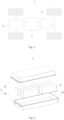
- Fig. 2 is an exploded view of a battery provided in some embodiments of the application. As shown in Fig. 2 , the battery 2 includes a box 5 and a battery cell (not shown in Fig. 2 ), and the battery cell is accommodated in the box 5.
- the box 5 is used for accommodating the battery cell and may be of various structures.
- the box 5 may include a first box portion 51 and a second box portion 52, the first box portion 51 and the second box portion 52 may cover each other, and the first box portion 51 and the second box portion 52 define an accommodation space 53 for accommodating the battery cell together.
- the second box portion 52 may be of a hollow structure with an opening end, the first box portion 51 is of a plate-like structure, and the first box portion 51 covers an opening side of the second box portion 52 so as to form the box 5 with the accommodation space 53.
- the first box portion 51 and the second box portion 52 may be both of hollow structures with opening sides, and an opening side of the first box portion 51 covers the opening side of the second box portion 52 so as to form the box 5 with the accommodation space 53.
- the first box portion 51 and the second box portion 52 may be in various shapes, such as a cylinder or a cuboid.
- a sealing member such as a sealant or a sealing ring, may be arranged between the first box portion 51 and the second box portion 52.
- the first box portion 51 covers a top portion of the second box portion 52
- the first box portion 51 may also be referred to as an upper box cover
- the second box portion 52 may also be referred to as a lower box.
- the battery 2 includes a plurality of battery modules 6, and each of the battery modules 6 includes a plurality of battery cells 61; and the battery 2 further includes a bus component 7, through which the plurality of battery cells 61 in the battery module 6 may be electrically connected, so as to allow the plurality of battery cells 61 in the battery module 6 to be connected in parallel, series or combination thereof.
- the bus component 7 may further be used to connect the plurality of battery modules 6 in series, parallel or combination thereof to form a whole.
- the battery module 6 further includes two end plates 62 and two side plates 63, characterized in that the two end plates 62 are arranged on both ends of the plurality of battery cells 61 in the alignment direction, the two side plates 63 are arranged on both sides of the plurality of battery units 61, the two end plates 62 and the two side plates 63 are fixedly connected to form a substantially rectangular frame for holding the plurality of battery units 61.
- the battery 2 further includes a cable (not shown) electrically connected to the battery cell 61.
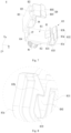
- Fig. 4 is a structural schematic diagram of a fixing member provided in some embodiments of the application
- Fig. 5 is a structural schematic diagram of a fixing member provided in some embodiments of the application when fixing a workpiece
- Fig. 6 is an enlarged view of the fixing member at the round frame A in Fig. 4
- Fig. 7 is a structural schematic diagram of the fixing member in Fig. 4 before clamping.
- the base 81 is installed in the external pedestal, and may be installed in, for example, a box of battery, an end plate, a bracket in a box or other fixed structures. In some embodiments, the base 81 is detachably connected to an external pedestal.
- the top cover 82 may be detachably connected or undetachably connected (e.g., welded) to the base 81.
- the top cover 82 and the base 81 may be independent members or two parts of an integrally formed member, and may be connected by their own structures or by other members (e.g. fasteners).
- the accommodating groove 83 may also be called an accommodating cavity, and is open at both ends.
- the workpiece may pass through the accommodating groove 83 via the opening thereof.
- the top wall 831 and the bottom wall 832 of the accommodating groove 83 are arranged opposite to each other in the first direction X, and may be curved walls or flat walls.
- the top wall 831 and the bottom wall 832 of the accommodating groove 83 are both flat walls and arranged in parallel.
- the top wall 831 and the bottom wall 832 of the accommodating groove 83 are perpendicular to the first direction X.
- the first elastic member 84 When the workpiece passes through the accommodating groove 83, the first elastic member 84 abuts against the workpiece from one side thereof in the first direction X.
- the first elastic member 84 is elastically deformed under the action of the workpiece; correspondingly, the first elastic member 84 applies an elastic force to the workpiece to abut against the workpiece.
- the first elastic member 84 is arranged on one side, close to the top wall 831, of the workpiece in the first direction X, or on one side, close to the bottom wall 832, of the workpiece in the first direction X, or on both sides of the workpiece in the first direction X.
- the first elastic member 84 is arranged on one side, close to the top wall 831, of the workpiece in the first direction X, and abuts against the workpiece, enabling the workpiece to abut against the bottom wall 832 and to be fixed between the first elastic member 84 and the bottom wall 832.
- the first elastic member 84 is arranged on one side, close to the bottom wall 832, of the workpiece in the first direction X, and abuts against the workpiece so that the workpiece abuts against the top wall 831 and is thus fixed between the first elastic member 84 and the top wall 831.
- the first elastic members 84 are arranged at both sides of the workpiece in the first direction X to abut against and fix the workpiece from both sides.
- the two inner side walls of the accommodating groove 83 are arranged opposite to each other in the second direction Y, and may be curved walls or flat walls.
- the two inner side walls of the accommodating groove 83 are flat walls and arranged in parallel, and optionally, the two inner side walls are perpendicular to the second direction Y.
- the two inner side walls of the accommodating groove 83 may be referred to as a first inner side wall 833 and a second inner side wall 834, respectively.
- the peripheral wall surrounding the accommodating groove 83 includes a top wall 831, a bottom wall 832, a first inner side wall 833 and a second inner side wall 834.
- the peripheral wall may only include a top wall 831, a bottom wall 832, a first inner side wall 833 and a second inner side wall 834, and may also include other connecting walls.
- the peripheral wall further includes a first connecting wall connecting the top wall 831 and the first inner side wall 833; and the first connecting wall may be a flat wall, a curved wall or a wall of other shapes.
- the peripheral wall may further include a second connecting wall, a third connecting wall, and the like.
- the second elastic member 85 is arranged between the two inner side walls of the accommodating groove 83, can be connected to either the first inner side wall 833 or the second inner side wall 834.
- the second elastic member 85 has an elastic structure, which may be elastically deformed to a certain extent due to good elasticity.
- the number of the second elastic members 85 may be one or more. In some examples, the number of the second elastic member 85, which is arranged on one inner side wall, may be one. In other examples, the number of the two second elastic members 85 may be two or more, and the two second elastic members 85 are arranged on the two inner side walls respectively. In still other examples, the number of the two second elastic members 85 is two or more, and the two second elastic members 85 are arranged on the same inner side wall.
- the second elastic member 85 When the workpiece passes through the accommodating groove 83, the second elastic member 85 abuts against the workpiece from one side thereof in the second direction Y.
- the second elastic member 85 is elastically deformed under the action of the workpiece; correspondingly, the second elastic member 85 applies an elastic force to the workpiece to abut against the workpiece.
- the second elastic member 85 is arranged on one side of the workpiece in the second direction Y, or on both sides of the workpiece in the second direction Y.
- the second elastic member 85 is arranged on one side of the workpiece in the second direction Y, and abuts against the workpiece, enabling the workpiece to abut against an inner side wall and to be fixed between the second elastic member 85 and the inner side wall.
- the second elastic members 85 which are arranged on both sides of the workpiece in the second direction Y, abut against and fix the workpiece from both sides.
- the first elastic member 84 can abut against and fix the workpiece in the first direction X
- the second elastic member 85 can abut against and fix the workpiece in the second direction Y.
- the fixing member 8 according to an embodiment of the application may fix the workpiece in the first direction X and the second direction Y, thereby improving the stability of the workpiece, reducing the risk of joint failure of the workpiece and the battery cell and improving the working performance of the battery.
- the fixing member 8 can realize the movement of the workpiece and reduce the difficulty of adjusting the position of the workpiece.
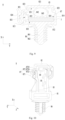
- the fixing member 8 further includes a mounting part 86 which is arranged on one side, facing away from the top cover 82, of the base 81, and connected to the base 81.
- the mounting part 86 is installed in the external pedestal and includes a clamping shaft 861 and a plurality of elastic cards 862 protruding from the outer peripheral surface thereof.
- the external pedestal is provided with a mounting hole fitting into the mounting part 86, through which the clamping shaft 861 of the mounting part 86 passes. When the clamping shaft 861 passes through the mounting hole, the elastic card 862 deforms under the action of the clamping shaft 861 and the wall of the mounting hole.
- the top cover 82 includes a body portion 821, an inner wall, facing the base 81, of the body portion 821 is configured to constitute at least part of the top wall 831, and the first elastic member 84 is arranged on the body portion 821 of the top cover 82.
- the inner wall, facing the base 81, of the body portion 821 may constitute part or all of the top wall 831.
- the first elastic member 84 is connected to the body portion 821 and protrudes from an inner wall thereof. When the bus component 7 passes through the accommodating groove 83, the first elastic member 84 abuts the bus component 7 against the bottom wall 832 of the accommodating groove 83.
- the body portion 821 is generally flat.
- the top cover 82 includes a body portion 821, and at least two bent portions 822 connected to both ends of the body portion 821 respectively in the second direction Y, and each of the bent portions 822 is bent towards one side close to the base 81 with respect to the body portion 821.
- the second through holes 823 of the two bent portions 822 allow an external strap to pass through.
- a bus component is arranged on one side, facing away from the base 81, of the body portion 821 (hereinafter referred to as an upper bus component)
- a strap may be used to pass through the second through holes 823 of the two bent portions 822 and surround the body portion 821 and the upper bus component to fix the upper bus component and the top cover 82 together.
- the first elastic member 84 is provided with a third through hole 841, and the projection of the second through hole 823 in the second direction Y at least partially overlaps with the projection of the third through hole 841 in the second direction Y.
- the first elastic member 84 includes a first elastic portion 842 connected to the body portion 821 of the top cover 82, and a first abutting portion 843 connected to one end, facing away from the body portion 821, of the first elastic portion 842.
- the first abutting portion 843 and the bottom wall 832 are arranged at intervals, and the first abutting portion 843 is configured to abut against the bus component 7 to fix the bus component 7 between the first abutting portion 843 and the bottom wall 832.
- the first elastic portion 842 is an elastically deformable part of the first elastic member 84.
- the first elastic portion 842 is elastically deformed to produce an elastic force, which acts on the bus component 7 through the first abutting portion 843.
- the first abutting portion 843 and the top wall 831 are arranged at intervals, and the first elastic portion 842 is arranged between the first abutting portion 843 and the top wall 831.
- the distance between the first abutting portion 843 and the top wall 831 and the distance between the first abutting portion 843 and the bottom wall 832 may be changed by changing the deformation amount of the first elastic portion 842.
- At least part of the first elastic portion 842 is arc-shaped.
- the arc-shaped structure has good elasticity, which is helpful to improving the elastic deformation ability of the first elastic portion 842.
- the first elastic member 84 includes at least two first elastic portions 842 arranged at intervals in the second direction Y. In the first direction X, the two first elastic portions 842 are located between the first abutting portion 843 and the body portion 821, and may improve the stress uniformity of the first abutting portion 843 and enhance the stability of the bus component 7.
- the first elastic portion 842 includes a first base portion 842a connected to a surface, facing the body portion 821, of the first abutting portion 843, and having two first surfaces 8421 arranged opposite to each other in the thickness direction thereof; a first supporting portion 842b connecting the body portion 821 and one end, facing away from the first abutting portion 843 of the first base portion 842a; a first protrusion portion 842c protruding from the first surface 8421 of the first base portion 842a; and a second supporting portion 842d connecting the first protrusion portion 842c and the body portion 821, characterized in that the first supporting portion 842b and the second supporting portion 842d are arranged at intervals in a third direction Z which intersects with both the first direction X and the second direction Y.
- the first supporting portion 842b and the second supporting portion 842d are arranged at intervals in the third direction Z, arranged therebetween a third through hole 841 which may reduce the strength of the first supporting portion 842b and the second supporting portion 842d, and improve the elasticity of the first supporting portion 842b and the second supporting portion 842d.
- the third through hole 841 may also provide an avoidance space for the strap to avoid the first elastic member 84 interfering with the strap.
- the first supporting portion 842b is connected to an end face, facing away from the first abutting portion 843, of the first base portion 842a, and the end face of the first base portion 842a is connected to the two first surfaces 8421.
- the first protrusion portion 842c is provided to allow the second supporting portion 842d to avoid the end face of the first base portion 842a, and the first supporting portion 842b and the second supporting portion 842d are arranged in a staggered manner.
- the first supporting portion 842b and the second supporting portion 842d may be punched. Since the first supporting portion 842b and the second supporting portion 842d are arranged in a staggered manner and do not overlap in the third direction Z, the first supporting portion 842b and the second supporting portion 842d may be formed after punched twice in the third direction Z.
- the first protrusion portion 842c protrudes from a first surface 8421 inside the first base portion 842a.
- the third direction Z is perpendicular to the first direction X and the second direction Y.
- a groove 811 is formed on the base 81 and constitutes at least part of the accommodating groove 83.
- the groove 811 of the base 81 may constitute part or all of the accommodating groove 83.
- the groove 811 is provided with an opening in one end in the first direction X, which is covered by the top cover 82.
- the bus component 7 and the fixing member 8 may be assembled according to the following steps: opening the top cover 82 to detach the top cover 82 from the first limiting part 813, and rotating the top cover 82 around the connecting member 87; placing the bus component 7 in the groove 811 of the base 81; and rotating the top cover 82 to clamp the top cover 82 to the first limiting part 813.
- the thickness of at least part of the connecting member 87 is smaller than that of the second limiting part 814.
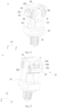
- Fig. 8 is an enlarged view of the fixing member at the round frame B in Fig. 4 .
- the first limiting part 813 includes a limiting plate 8131, and a clamping seat 8132 connected to the limiting plate 8131 and located at one side, away from the second limiting part 814, of the limiting plate 8131, and a clamping slot 8133 is formed between the limiting plate 8131 and the clamping seat 8132.
- the top cover 82 includes a buckling portion 824 used for being inserted into the clamping slot 8133 and clamped on the clamping seat 8132.
- An inner wall, facing the second limiting part 814, of the first limiting plate 8131 may be used as the first inner side wall 833 of the accommodating groove 83.
- the buckling portion 824 may be directly connected to the body portion 821, or indirectly connected to the body portion 821, for example, through the bent portion 822.
- the buckling portion 824 includes a first clamping portion 8241 and a second clamping portion 8242, which are arranged in a third direction Z intersecting with both the first direction X and the second direction Y.
- the clamping seat 8132 includes a third clamping portion 813a and a fourth clamping portion 813b arranged in the third direction Z.
- the first clamping portion 8241 is located on one side, facing the bottom wall 832, of the third clamping portion 813a
- the second clamping portion 8242 is located on one side, facing the bottom wall 832, of the fourth clamping portion 813b when the buckling portion 824 is clamped to the clamping seat 8132.
- a clamping surface between the first clamping portion 8241 and the third clamping portion 813a and a clamping surface between the second clamping portion 8242 and the fourth clamping portion 813b are arranged in a staggered way in the first direction X and/or the second direction Y.
- the first clamping portion 8241 and the second clamping portion 8242 may be continuously arranged in the third direction Z, or arranged at intervals in the third direction Z; while the third clamping portion 813a and the fourth clamping portion 813b may be continuously arranged in the third direction Z, or arranged at intervals in the third direction Z.
- the clamping seat 8132 is configured to be elastic and deformable. When it is necessary to open the top cover 82, the clamping seat 8132 may be rotated to detach the third clamping portion 813a from the first clamping portion 8241, and to detach the fourth clamping portion 813b from the second clamping portion 8242.
- the clamping seat 8132 includes a bent portion 813c connected to the limiting plate 8131, and the first and second clamping portions 8241 and 8242 are connected to one end, away from the limiting plate 8131, of the bent portion 813c.
- the bent portion 813c is configured to be elastically deformable under stress.
- a clamping surface between the first clamping portion 8241 and the third clamping portion 813a and a clamping surface between the second clamping portion 8242 and the fourth clamping portion 813b are arranged in a staggered way in the first direction X and/or the second direction Y, so as to form a two-stage buckle structure which can improve the structural stability and reduce the risk of the buckling portion 824 falling out of the clamping slot 8133.
- the connecting member 87 includes a deformation portion 871 rotatably connected to the second limiting part 814, and a connecting portion 872 connected to the deformation portion 871 and the top cover 82 and provided with a backstop portion 8721.
- the base 81 is provided with a first convex rib 815 protruding from the second limiting part 814; when the top cover 82 is clamped to the first limiting part 813, the first convex rib 815 fits with the backstop portion 8721 to limit the movement of the connecting portion 872 in the first direction X away from the base 81.
- the first convex rib 815 can strengthen the local strength of the second limiting part 814.
- the top cover 82 pulls the deformation portion 871 and the connecting portion 872; and the first convex rib 815 may fit with the backstop portion 8721 to limit the movement of the connecting portion 872 in the first direction X away from the base 81, avoiding excessive deformation of the deformation portion 871.
- the second convex rib 816 can strengthen the local strength of the second limiting part 814.
- the top cover 82 pulls the deformation portion 871 and the connection part 872; and the second convex rib 816 may abut against the connecting portion 872 to limit the movement of the connecting portion 872 in a direction towards the second limiting part 814, avoiding excessive deformation of the deformation portion 871 under the action of the connecting portion 872.
- first convex rib 815 and the second convex rib 816 are integrally formed, and may be continuously arranged in the third direction Z.
- the first convex rib 815 and the second convex rib 816 are arranged in a staggered manner in the first direction X.
- the first convex rib 815 is located on one side, away from the deformation portion 871, of the stopper 8721 to limit the movement of the backstop portion 8721 in the first direction X
- the second convex rib 816 is located between the backstop portion 8721 and the second limiting part 814 to limit the movement of the backstop portion 8721 in the second direction Y.
- the connecting portion 872 is provided with a first through hole 8722
- the backstop portion 8721 is formed on one side, close to the deformation portion 871, of the first through hole 8722
- the first convex rib 815 is inserted into the first through hole 8722 to fix with the backstop portion 8721 when the top cover 82 is clamped to the first limiting part 813.
- the strength of the connecting portion 872 can be reduced by providing the first through hole 8722; in this way, the connecting portion 872 can be adaptively deformed in the opening or closing process of the top cover 82.
- the first through hole 8722 provides a space for the first convex rib 815, which is convenient to realize the fitting of the first convex rib 815 with the backstop portion 8721.
- the backstop portion 8721 is connected to an end, facing away from the second limiting part 814, of the deformation portion 871.
- the connecting portion 872 further includes a second protrusion portion 8723, a first extension portion 8724 and a second extension portion 8725.
- the second protrusion portion 8723 protrudes from a surface, facing the second limiting part 814, of the backstop portion 8721.
- the first extension portion 8724 is connected to the top cover 82 and one end, facing away from the deformation portion 871, of the backstop portion 8721.
- the second extension portion 8725 is connected to the second protrusion portion 8723 and the top cover 82.
- the first extension portion 8724 and the second extension portion 8725 are arranged at intervals in the third direction Z intersecting with both the first direction X and the second direction Y, and the first through hole 8722 is formed between the first extension portion 8724 and the second extension portion 8725.
- the first through hole 8722 may reduce the strength of the first extension portion 8724 and the second extension portion 8725, and improve the elasticity of the first extension portion 8724 and the second extension portion 8725.
- the first extension portion 8724 is connected to an end face, away from the deformation portion 871, of the backstop portion 8721.
- the second protrusion portion 8723 is provided so that the second extension portion 8725 may avoid the end face of the backstop portion 8721. In this way, the first extension portion 8724 and the second extension portion 8725 are arranged in a staggered way.
- the first extension portion 8724 and the second extension portion 8725 may be punched. Since the first extension portion 8724 and the second extension portion 8725 are arranged in a staggered manner and do not overlap in the third direction Z, the first extension portion 8724 and the second extension portion 8725 may be formed after punched twice in the third direction Z.
- Fig. 14 is a schematic flow chart of a method for manufacturing a battery provided in some embodiments of the application.
- the first elastic member is configured to abut against the bus component in a first direction to fix the bus component between the top wall and the bottom wall
- the second elastic member is configured to abut against the bus component in a second direction to fix the bus component between two inner side walls of the accommodating groove, the first direction intersects with the second direction.
- the batteries provided in the above embodiments can be made as a reference to the related structure of the battery manufactured by the above manufacturing method.
- step S100 and step S400 may be performed in no particular order, or at the same time.
- Fig. 15 is a schematic block diagram of a system for manufacturing a battery provided in some embodiments of the application.
- a system 9 for manufacturing a battery includes a first supply device 91, configured to provide an external pedestal; a second supply device 92, configured to provide a battery cell and install the battery cell in the external pedestal; a third supply device 93, configured to provide a bus component and electrically connecting the bus component to the battery cell; a fourth supply device 94, configured to provide a fixing member which includes a base, a top cover, a first elastic member and a second elastic member, characterized in that the base is connected to the top cover, an accommodating groove is formed between the base and the top cover, the first elastic member is provided between the top wall and the bottom wall of the accommodating groove, and the second elastic member is provided between the two inner walls of the accommodating groove; and an assembly device 95, connecting the base to the external pedestal, and accommodating part of the bus component in the accommodating groove, characterized in that the first elastic member is configured to abut against the bus component in a first direction to fix the bus component between the top wall and the bottom wall
- the batteries provided in the above embodiments can be made as a reference to the related structure of the battery manufactured by the above manufacturing method.
Landscapes
- Chemical & Material Sciences (AREA)
- Chemical Kinetics & Catalysis (AREA)
- Electrochemistry (AREA)
- General Chemical & Material Sciences (AREA)
- Engineering & Computer Science (AREA)
- Manufacturing & Machinery (AREA)
- Materials Engineering (AREA)
- Mechanical Engineering (AREA)
- Battery Mounting, Suspending (AREA)
- Installation Of Indoor Wiring (AREA)
- Connection Of Batteries Or Terminals (AREA)
Description
- The application relates to the technical field of batteries, and more particularly relates to a fixing member, a battery, an electric device, and a method and system for manufacturing the battery.
- Battery cells are widely used in electronic devices such as mobile phones, laptops, battery cars, electric vehicles, electric aircrafts, electric boats, electric toy cars, electric toy boats, electric toy planes, electric tools, etc. Battery cells can include nickel-cadmium battery cells, nickel-hydrogen battery cells, lithium ion battery cells and secondary alkaline zinc-manganese battery cells.
-
JP2012138333 (A busbar holder 4 which is formed by abody part 7 having busbar storage portions 15 capable of storingbusbars 3, and alid part 9 connected to thebody part 7 byhinges 8. Thebusbars 3 have a clearance in the busbar storage portions 15 permitting a predetermined displacement in the direction of arrangement ofbatteries 1. Ifinsertion holes 5 in anybusbar 3 are not aligned withcorresponding electrodes 2, thebusbar 3 can be displaced in the arrangement direction to align theinsertion holes 5 with the electrodes to be inserted. As to the displacement of thebusbar 3,support pieces 6 protruded from the busbar fit in guide portions 16 formed in thebody part 7 to support the displacement of thebusbar 3.WO2010001477A1 discloses an electric wire holder capable of sufficiently functioning without causing an extreme deterioration in its firm sticking with an electric wire even if the kind or the like of the wire is slightly changed. The wire holder (1) is formed in a generally cylindrical body installable on the chassis (2) of an electronic appliance. A clamp part (20) is formed of an elastic member, and disposed in a support part for supporting the wire (3) inserted into the central opening of the wire holder (1). The clamp part (20) holds the wire (3) while drivingly contacting at its tip end against the outer surface of the wire (3). The clamp part (20) is electrically conductive to the chassis (2) through the support part. -
JP2005160273A clip 1 sandwiching and retaining a laminated bus bar 50 which layers twobus bars insulation sheet 51, and is the bus bar fixing device for fixing the laminated bus bar 50 in a battery. This bus bar fixing device has first and second retaining portions 10, 20 for sandwiching the laminated bus bar 50 so as to face each other, a bent portion 30 for opening/closing the first and second retaining portions 10, 20 for inserting the laminated bus bar 50, and a fixing portion 40 for fixing theclip 1 at a basket body and the like for the battery. Portions 11, 21 which are brought into contact with the laminated bus bar 50 at least in the first and second retaining portions 10, 20 are constituted of first synthetic resin material which has excellent heat resistance and prevents thermal deformation. The bent portion 30 is constituted of the second synthetic resin material having a lower Young's modulus than the first synthetic resin material and high bent strength. - A plurality of battery cells are assembled together to form a battery, when used in groups. In related art, as the battery vibrates, some workpieces contained therein may be easily driven to vibrate, which affects the stability of the battery.
- The application provides a fixing member, a battery, an electric device and a method and system for manufacturing the battery, which can reduce the shaking of a workpiece and improve the stability of the battery.
- In a first aspect, the application provides a fixing member for fixing a workpiece as defined in
claim 1, preferred embodiments are defined in dependent claims 2-11, which includes: - a base for connecting an external pedestal;
- a top cover connected to the base, an accommodating groove for accommodating the workpiece being formed between the base and the top cover;
- a first elastic member arranged between the top wall and the bottom wall of the accommodating groove, and configured to abut against the workpiece in a first direction to fix the workpiece between the top wall and the bottom wall; and
- a second elastic member arranged between two inner side walls of the accommodating groove, and configured to abut against the workpiece in a second direction to fix the workpiece between the two inner side walls of the accommodating groove, with the first direction intersecting with the second direction.
- In the above solution, the first elastic member can abut against the workpiece in the first direction to fix the workpiece in the first direction, and the second elastic member can abut against the workpiece in the second direction to fix the workpiece in the second direction. The fixing member according to an embodiment of the application may fix the workpiece in the first direction and the second direction, thereby improving the stability of the workpiece, reducing the risk of joint failure of the workpiece and the battery cell and improving the working performance of the battery.
- When the position of the workpiece needs to be adjusted, the workpiece is forced by an operator or operating equipment to squeeze the first elastic member and the second elastic member, which are deformed due to the elastic deformation ability, so as to realize the movement of the workpiece. Therefore, the fixing member according to an embodiment of the application can realize the movement of the workpiece and reduce the difficulty of adjusting the position of the workpiece.
- Based on the elastic deformation ability of the first elastic member, the space occupied by the first elastic member in the first direction can be adjusted by changing the elastic deformation amount of the first elastic member; as a result, the first elastic member may fix workpieces with different sizes in the first direction. Likewise, based on the elastic deformation ability of the second elastic member, the space occupied by the second elastic member in the second direction can be adjusted by changing the elastic deformation amount of the second elastic member; as a result, the second elastic member may fix workpieces with different sizes in the second direction. In a word, the fixing member according to an embodiment of the application can be used for fixing workpieces of various specifications, and has good universality.
- In a second aspect, the application provides a battery as defined in claim 12.
- In a third aspect, the application provides a method for manufacturing a battery as defined in claim 13.
- In order to describe the technical solutions in the embodiments of the application more clearly, the accompanying drawings required for describing the embodiments are briefly described below. Obviously, the accompanying drawings in the following description show merely some embodiments of the present disclosure, and a person of ordinary skill in the art would also be able to derive other accompanying drawings from these accompanying drawings without creative efforts.
-
Fig. 1 is a structural schematic diagram of a vehicle provided in some embodiments of the application; -
Fig. 2 is an exploded view of a battery provided in some embodiments of the application; -
Fig. 3 is a schematic diagram of a partial structure of a battery provided in some embodiments of the application. -
Fig. 4 is a structural schematic diagram of a fixing member provided in some embodiments of the application. -
Fig. 5 is a structural schematic diagram of a fixing member provided in some embodiments of the application when fixing a workpiece. -
Fig. 6 is an enlarged view of the fixing member at the round frame A inFig. 4 . -
Fig. 7 is a structural schematic diagram of the fixing member inFig. 4 before clamping. -
Fig. 8 is an enlarged view of the fixing member at the round frame B inFig. 4 . -
Fig. 9 is a structural schematic diagram of a fixing member provided in some other embodiments of the application when fixing a workpiece. -
Fig. 10 is a structural schematic diagram of a fixing member provided in some other embodiments of the application. -
Fig. 11 is a structural schematic diagram of the fixing member at another angle inFig. 10 . -
Fig. 12 is a structural schematic diagram of the fixing member at still another angle inFig. 10 . -
Fig. 13 is an enlarged view of the fixing member at the round frame C inFig. 12 . -
Fig. 14 is a schematic flow chart of a method for manufacturing a battery provided in some embodiments of the application. -
Fig. 15 is a schematic block diagram of a system for manufacturing a battery provided in some embodiments of the application. - In the drawings, the components are not drawn to actual scale.
- To make the objectives, technical solutions, and advantages of the embodiments of the application clearer, the following will clearly describe the technical solutions in the embodiments of the application with reference to the accompanying drawings in the embodiments of the application. Apparently, the described embodiments are some rather than all of the embodiments of the application.
- In the application, battery cells may include a lithium ion secondary battery cell, a lithium ion primary battery cell, a lithium-sulfur battery, a sodium lithium-ion battery cell, a sodium ion battery cell, a magnesium ion battery cell, etc., which are not limited by the embodiments of the application. The battery cell may be in cylindrical, flat, cuboid or other shapes, which is not limited by the embodiments of the application. Generally, the battery cells are divided into three types according to packaging manners: cylindrical battery cells, square battery cells and pouch battery cells, which are not limited by the embodiments of the application.
- The battery mentioned in the embodiments of the application refers to a single physical module which includes one or a plurality of battery cells and therefore provides a higher voltage and capacity. Generally, the battery includes a box for packaging one or a plurality of battery cells. The box may prevent liquid or other foreign matter from affecting charging or discharging of the battery cell.
- The battery cell includes an electrode assembly and an electrolyte, and the electrode assembly includes a positive pole piece, a negative pole piece and a separator. The battery cell works mainly depending on movement of metal ions between the positive pole piece and the negative pole piece. The positive pole piece includes a positive current collector and a positive active material layer coated on a surface of the positive current collector; the positive current collector includes a positive current collecting portion and a positive protrusion portion protruding from the positive current collecting portion, the positive current collecting portion is coated with the positive active material layer, at least part of the positive protrusion portion is not coated with the positive active material layer, and the positive protrusion portion serves as a positive tab.
- Taking a lithium ion battery as an example, the positive current collector may be made of aluminum, and the positive active material layer includes a positive active material which may be lithium cobaltate, lithium iron phosphate, ternary lithium or lithium manganate. The negative pole piece includes a negative current collector and a negative active material layer coated on a surface of the negative current collector; the negative current collector includes a negative current collecting portion and a negative protrusion portion protruding from the negative current collecting portion, the negative current collecting portion is coated with the negative active material layer, at least part of the negative protrusion portion is not coated with the negative active material layer, and the negative protrusion portion serves as a negative tab. The negative current collector may be made of copper, and the negative active material layer includes a negative active material which may be carbon or silicon. In order to guarantee fusing does not occur during large current flow, a plurality of positive tabs are stacked together, and a plurality of negative tabs are stacked together. The separator may be made of polypropylene (PP) or polyethylene (PE). In addition, the electrode assembly may be in a wound structure or a laminated structure, which is not limited in the embodiments of the application.
- The inventors found that a battery generally includes a workpiece electrically connected to a battery cell, and some workpieces (e.g. bus component, high-voltage connecting member and cable) are relatively long. The workpieces such as bus components and cables are easy to shake as the battery vibrates, which leads to a risk of joint failure of the workpiece and the battery cell, and affects working performance and service life of the battery.
- The inventors tried to fix the workpiece with a strap, for example, to bind a bus component or cable to other components of the battery, so as to improve the stability of the workpiece and reduce the shaking of the workpiece when the battery vibrates. However, the inventors found it difficult to displace or adjust the position of the workpiece after fastened with a strap; and the strap must be cut off to remove the workpiece, which operation is complicated.
- In view of this, an embodiment of the application provides a fixing member for fixing a workpiece, which includes a base for connecting an external pedestal; a top cover connected to the base, an accommodating groove for accommodating the workpiece being formed between the base and the top cover; a first elastic member arranged between the top wall and the bottom wall of the accommodating groove, and configured to abut against the workpiece in a first direction to fix the workpiece between the top wall and the bottom wall; and a second elastic member arranged between two inner side walls of the accommodating groove, and configured to abut against the workpiece in a second direction to fix the workpiece between the two inner side walls of the accommodating groove, with the first direction intersecting with the second direction. The fixing member according to an embodiment of the application can effectively fix the workpiece, simplify the assembly process of the fixing member and the workpiece, and can be applied to workpieces of various specifications.
- The fixing member described in an embodiment of the application is suitable for batteries and electric devices that use batteries.
- The electric devices may be vehicles, mobile phones, portable devices, laptops, ships, spacecraft, electric toys and electric tools. The vehicles may be fuel vehicles, gas vehicles or new energy vehicles, and the new energy vehicles may be battery electric vehicles, hybrid electric vehicles, extended-range vehicles, etc. The spacecrafts include airplanes, rockets, space shuttles, spaceships, etc. The electric toys include fixed or mobile electric toys, such as game machines, electric car toys, electric ship toys and electric airplane toys. The electric tools include metal cutting electric tools, electric grinding tools, electric assembling tools and electric tools for railways, such as electric drills, electric grinders, electric wrenches, electric screwdrivers, electric hammers, impact electric drills, concrete vibrators, electric planers, etc. The embodiment of the application does not impose special restrictions on the above-mentioned electric devices.
- For the sake of illustration, the following embodiments are illustrated with a vehicle as an electric device.
-
Fig. 1 is a schematic structural diagram of a vehicle provided in some embodiments of the application. As shown inFig. 1 , abattery 2 is disposed inside avehicle 1, and thebattery 2 may be disposed at the bottom, head or tail of thevehicle 1. Thebattery 2 may be used for supplying electricity to thevehicle 1, for example, thebattery 2 may be used as an operating power source for thevehicle 1. - The
vehicle 1 may further include acontroller 3 and amotor 4, where thecontroller 3 is used for controlling thebattery 2 to supply electricity to themotor 4 to be used for, for example, operating electricity requirements during start-up, navigation and running of thevehicle 1. - In some embodiments of the application, the
battery 2 may not only serve as the operating power source for thevehicle 1, but also serve as a driving power source for thevehicle 1, so as to replace or partially replace fuel or natural gas to provide driving power for thevehicle 1.Fig. 2 is an exploded view of a battery provided in some embodiments of the application. As shown inFig. 2 , thebattery 2 includes abox 5 and a battery cell (not shown inFig. 2 ), and the battery cell is accommodated in thebox 5. - The
box 5 is used for accommodating the battery cell and may be of various structures. In some embodiments, thebox 5 may include afirst box portion 51 and asecond box portion 52, thefirst box portion 51 and thesecond box portion 52 may cover each other, and thefirst box portion 51 and thesecond box portion 52 define anaccommodation space 53 for accommodating the battery cell together. Thesecond box portion 52 may be of a hollow structure with an opening end, thefirst box portion 51 is of a plate-like structure, and thefirst box portion 51 covers an opening side of thesecond box portion 52 so as to form thebox 5 with theaccommodation space 53. Thefirst box portion 51 and thesecond box portion 52 may be both of hollow structures with opening sides, and an opening side of thefirst box portion 51 covers the opening side of thesecond box portion 52 so as to form thebox 5 with theaccommodation space 53. Of course, thefirst box portion 51 and thesecond box portion 52 may be in various shapes, such as a cylinder or a cuboid. - In order to improve sealability after the
first box portion 51 and thesecond box portion 52 are connected, a sealing member, such as a sealant or a sealing ring, may be arranged between thefirst box portion 51 and thesecond box portion 52. - Assuming that the
first box portion 51 covers a top portion of thesecond box portion 52, thefirst box portion 51 may also be referred to as an upper box cover, and thesecond box portion 52 may also be referred to as a lower box. - There may be one or more battery cells in the
battery 2. If there are a plurality of battery cells, the plurality of battery cells may be connected in series, in parallel, or in a series-parallel manner. A plurality of battery cells may be directly connected in series, parallel or combination thereof, and then the whole formed by the plurality of battery cells is accommodated in thebox 5; certainly, it is also possible that a plurality of battery cells are connected in series, parallel or combination thereof to form abattery module 6, and then a plurality ofbattery modules 6 are connected in series, parallel or combination thereof to form a whole through a bus component, which is then accommodated in thebox 5. -
Fig. 3 is a schematic diagram of a partial structure of a battery provided in some embodiments of the application. - As shown in
Fig. 3 , in some embodiments, thebattery 2 includes a plurality ofbattery modules 6, and each of thebattery modules 6 includes a plurality ofbattery cells 61; and thebattery 2 further includes abus component 7, through which the plurality ofbattery cells 61 in thebattery module 6 may be electrically connected, so as to allow the plurality ofbattery cells 61 in thebattery module 6 to be connected in parallel, series or combination thereof. Thebus component 7 may further be used to connect the plurality ofbattery modules 6 in series, parallel or combination thereof to form a whole. - In some embodiments, the
battery module 6 further includes twoend plates 62 and twoside plates 63, characterized in that the twoend plates 62 are arranged on both ends of the plurality ofbattery cells 61 in the alignment direction, the twoside plates 63 are arranged on both sides of the plurality ofbattery units 61, the twoend plates 62 and the twoside plates 63 are fixedly connected to form a substantially rectangular frame for holding the plurality ofbattery units 61. In some embodiments, thebattery 2 further includes a cable (not shown) electrically connected to thebattery cell 61. - The fixing
member 8 provided in an embodiment of the application can effectively fix the workpiece, simplify the assembly process of the fixingmember 8 and the workpiece, and can be applied to workpieces of various specifications. The workpiece fixed by the fixingmember 8 according to the application may be abus component 7, a cable, a high-voltage connecting member or other workpieces applied in thebattery 2. - The fixing
member 8 according to an embodiment of the application is used to connect the external pedestal of thebattery 2. The external pedestal is a component for mounting the fixingmember 8, and is determined according to the position of the workpiece fixed by the fixingmember 8. For example, the external pedestal may be the box of thebattery 2, theend plate 62, the bracket in the box or other fixed structures. -
Fig. 4 is a structural schematic diagram of a fixing member provided in some embodiments of the application;Fig. 5 is a structural schematic diagram of a fixing member provided in some embodiments of the application when fixing a workpiece;Fig. 6 is an enlarged view of the fixing member at the round frame A inFig. 4 ; andFig. 7 is a structural schematic diagram of the fixing member inFig. 4 before clamping. - As shown in
Figs. 4 to 7 , the fixingmember 8 according to an embodiment of the application is used for fixing a workpiece. The fixingmember 8 includes abase 81 for connecting an external pedestal; atop cover 82 connected to thebase 81, anaccommodating groove 83 for accommodating the workpiece being formed between the base 81 and thetop cover 82; a firstelastic member 84 arranged between thetop wall 831 and thebottom wall 832 of theaccommodating groove 83, and configured to abut against the workpiece in a first direction X to fix the workpiece between thetop wall 831 and thebottom wall 832; and a secondelastic member 85 arranged between two inner side walls of theaccommodating groove 83, and configured to abut against the workpiece in a second direction Y to fix the workpiece between the two inner side walls of theaccommodating groove 83, with the first direction X intersecting with the second direction Y. - The
base 81 is installed in the external pedestal, and may be installed in, for example, a box of battery, an end plate, a bracket in a box or other fixed structures. In some embodiments, thebase 81 is detachably connected to an external pedestal. - The
top cover 82 may be detachably connected or undetachably connected (e.g., welded) to thebase 81. Thetop cover 82 and the base 81 may be independent members or two parts of an integrally formed member, and may be connected by their own structures or by other members (e.g. fasteners). - The
accommodating groove 83 may also be called an accommodating cavity, and is open at both ends. The workpiece may pass through theaccommodating groove 83 via the opening thereof. - The
top wall 831 and thebottom wall 832 of theaccommodating groove 83 are arranged opposite to each other in the first direction X, and may be curved walls or flat walls. Exemplarily, thetop wall 831 and thebottom wall 832 of theaccommodating groove 83 are both flat walls and arranged in parallel. Optionally, thetop wall 831 and thebottom wall 832 of theaccommodating groove 83 are perpendicular to the first direction X. - The first
elastic member 84 is arranged between thetop wall 831 and thebottom wall 832 of theaccommodating groove 83, and may be connected to either thetop wall 831 or thebottom wall 832 of theaccommodating groove 83. - The first
elastic member 84 has an elastic structure, which may be elastically deformed to a certain extent due to good elasticity. - The number of the first
elastic members 84 may be one or more. In some examples, the number of the firstelastic member 84 is one, and the first elastic member may be arranged on thetop wall 831 or thebottom wall 832 of theaccommodating groove 83. In other examples, the number of the firstelastic member 84 is two or more, and the two firstelastic members 84 are arranged on thetop wall 831 and thebottom wall 832 of theaccommodating groove 83 respectively. In still other examples, the number of the firstelastic member 84 is two or more, and the two firstelastic members 84 are arranged on thetop wall 831 or thebottom wall 832 of theaccommodating groove 83. - When the workpiece passes through the
accommodating groove 83, the firstelastic member 84 abuts against the workpiece from one side thereof in the first direction X. The firstelastic member 84 is elastically deformed under the action of the workpiece; correspondingly, the firstelastic member 84 applies an elastic force to the workpiece to abut against the workpiece. - When the workpiece passes through the
accommodating groove 83, the firstelastic member 84 is arranged on one side, close to thetop wall 831, of the workpiece in the first direction X, or on one side, close to thebottom wall 832, of the workpiece in the first direction X, or on both sides of the workpiece in the first direction X. In some examples, the firstelastic member 84 is arranged on one side, close to thetop wall 831, of the workpiece in the first direction X, and abuts against the workpiece, enabling the workpiece to abut against thebottom wall 832 and to be fixed between the firstelastic member 84 and thebottom wall 832. In other examples, the firstelastic member 84 is arranged on one side, close to thebottom wall 832, of the workpiece in the first direction X, and abuts against the workpiece so that the workpiece abuts against thetop wall 831 and is thus fixed between the firstelastic member 84 and thetop wall 831. In still other examples, the firstelastic members 84 are arranged at both sides of the workpiece in the first direction X to abut against and fix the workpiece from both sides. - The two inner side walls of the
accommodating groove 83 are arranged opposite to each other in the second direction Y, and may be curved walls or flat walls. Exemplarily, the two inner side walls of theaccommodating groove 83 are flat walls and arranged in parallel, and optionally, the two inner side walls are perpendicular to the second direction Y. The two inner side walls of theaccommodating groove 83 may be referred to as a firstinner side wall 833 and a secondinner side wall 834, respectively. - The peripheral wall surrounding the
accommodating groove 83 includes atop wall 831, abottom wall 832, a firstinner side wall 833 and a secondinner side wall 834. The peripheral wall may only include atop wall 831, abottom wall 832, a firstinner side wall 833 and a secondinner side wall 834, and may also include other connecting walls. For example, the peripheral wall further includes a first connecting wall connecting thetop wall 831 and the firstinner side wall 833; and the first connecting wall may be a flat wall, a curved wall or a wall of other shapes. - Certainly, the peripheral wall may further include a second connecting wall, a third connecting wall, and the like.
- The second
elastic member 85 is arranged between the two inner side walls of theaccommodating groove 83, can be connected to either the firstinner side wall 833 or the secondinner side wall 834. - The second
elastic member 85 has an elastic structure, which may be elastically deformed to a certain extent due to good elasticity. - The number of the second
elastic members 85 may be one or more. In some examples, the number of the secondelastic member 85, which is arranged on one inner side wall, may be one. In other examples, the number of the two secondelastic members 85 may be two or more, and the two secondelastic members 85 are arranged on the two inner side walls respectively. In still other examples, the number of the two secondelastic members 85 is two or more, and the two secondelastic members 85 are arranged on the same inner side wall. - When the workpiece passes through the
accommodating groove 83, the secondelastic member 85 abuts against the workpiece from one side thereof in the second direction Y. The secondelastic member 85 is elastically deformed under the action of the workpiece; correspondingly, the secondelastic member 85 applies an elastic force to the workpiece to abut against the workpiece. - When the workpiece passes through the
accommodating groove 83, the secondelastic member 85 is arranged on one side of the workpiece in the second direction Y, or on both sides of the workpiece in the second direction Y. In some examples, the secondelastic member 85 is arranged on one side of the workpiece in the second direction Y, and abuts against the workpiece, enabling the workpiece to abut against an inner side wall and to be fixed between the secondelastic member 85 and the inner side wall. In other examples, the secondelastic members 85, which are arranged on both sides of the workpiece in the second direction Y, abut against and fix the workpiece from both sides. - The first direction X intersects with the second direction Y, and optionally, the first direction X is perpendicular to the second direction Y. The
accommodating groove 83 is open at both ends in a third direction Z, which intersects with both the first direction X and the second direction Y; illustratively, the third direction Z is perpendicular to the first direction X and the second direction Y. - In the fixing
member 8 according to an embodiment of the application, the firstelastic member 84 can abut against and fix the workpiece in the first direction X, and the secondelastic member 85 can abut against and fix the workpiece in the second direction Y. The fixingmember 8 according to an embodiment of the application may fix the workpiece in the first direction X and the second direction Y, thereby improving the stability of the workpiece, reducing the risk of joint failure of the workpiece and the battery cell and improving the working performance of the battery. - When the position of the workpiece needs to be adjusted, the workpiece is forced by an operator or operating equipment to squeeze the first
elastic member 84 and the secondelastic member 85, which are deformed due to the elastic deformation ability, so as to realize the movement of the workpiece. Therefore, the fixingmember 8 according to an embodiment of the application can realize the movement of the workpiece and reduce the difficulty of adjusting the position of the workpiece. - Based on the elastic deformation ability of the first
elastic member 84, the space occupied by the firstelastic member 84 in the first direction X can be adjusted by changing the elastic deformation amount of the firstelastic member 84; as a result, the firstelastic member 84 may fix workpieces with different sizes in the first direction X. Likewise, based on the elastic deformation ability of the secondelastic member 85, the space occupied by the secondelastic member 85 in the second direction Y can be adjusted by changing the elastic deformation amount of the secondelastic member 85; as a result, the secondelastic member 85 may fix workpieces with different sizes in the second direction Y. In a word, the fixingmember 8 according to an embodiment of the application can be used for fixing workpieces of various specifications, and has good universality. - The workpiece fixed by the fixing
member 8 according to an embodiment of the application includes at least one of thebus component 7, the high-voltage connecting member and the cable. Optionally, the workpiece fixed by the fixingmember 8 according to an embodiment of the application is thebus component 7. - For convenience of description, an embodiment of the application will be described below with the
bus component 7 as a workpiece to be fixed by the fixingmember 8. - In some embodiments, the fixing
member 8 further includes a mountingpart 86 which is arranged on one side, facing away from thetop cover 82, of thebase 81, and connected to thebase 81. The mountingpart 86 is installed in the external pedestal and includes a clampingshaft 861 and a plurality ofelastic cards 862 protruding from the outer peripheral surface thereof. The external pedestal is provided with a mounting hole fitting into the mountingpart 86, through which the clampingshaft 861 of the mountingpart 86 passes. When the clampingshaft 861 passes through the mounting hole, theelastic card 862 deforms under the action of the clampingshaft 861 and the wall of the mounting hole. When the clampingshaft 861 reaches the set position, theelastic card 862 presses against the wall of the mounting hole under the action of elasticity, thereby fixing the mountingpart 86 on the external pedestal. Theelastic card 862 may also pass through the mounting hole and be clamped on one side, away from thebase 81, of the external pedestal. - The
top cover 82 includes abody portion 821, an inner wall, facing thebase 81, of thebody portion 821 is configured to constitute at least part of thetop wall 831, and the firstelastic member 84 is arranged on thebody portion 821 of thetop cover 82. - The inner wall, facing the
base 81, of thebody portion 821 may constitute part or all of thetop wall 831. The firstelastic member 84 is connected to thebody portion 821 and protrudes from an inner wall thereof. When thebus component 7 passes through theaccommodating groove 83, the firstelastic member 84 abuts thebus component 7 against thebottom wall 832 of theaccommodating groove 83. - In some embodiments, the
body portion 821 is generally flat. - In some embodiments, the
top cover 82 includes abody portion 821, and at least twobent portions 822 connected to both ends of thebody portion 821 respectively in the second direction Y, and each of thebent portions 822 is bent towards one side close to the base 81 with respect to thebody portion 821. - The two
bent portions 822 are provided with the second throughholes 823 aligned in the second direction Y. In other words, the projections of the two second throughholes 823 in the second direction Y at least partially overlap. - The second through
holes 823 of the twobent portions 822 allow an external strap to pass through. For example, when a bus component is arranged on one side, facing away from thebase 81, of the body portion 821 (hereinafter referred to as an upper bus component), a strap may be used to pass through the second throughholes 823 of the twobent portions 822 and surround thebody portion 821 and the upper bus component to fix the upper bus component and thetop cover 82 together. - In some embodiments, the first
elastic member 84 is provided with a third throughhole 841, and the projection of the second throughhole 823 in the second direction Y at least partially overlaps with the projection of the third throughhole 841 in the second direction Y. - When it is necessary to fix the upper bus component with a strap, the strap is made to pass through one side, facing the
base 81, of thebody portion 821. The third throughhole 841 is arranged to provide an avoidance space for the strap to avoid the firstelastic member 84 interfering with the strap. - The first
elastic member 84 includes a firstelastic portion 842 connected to thebody portion 821 of thetop cover 82, and a firstabutting portion 843 connected to one end, facing away from thebody portion 821, of the firstelastic portion 842. In the first direction X, the first abuttingportion 843 and thebottom wall 832 are arranged at intervals, and the first abuttingportion 843 is configured to abut against thebus component 7 to fix thebus component 7 between the first abuttingportion 843 and thebottom wall 832. - The first
elastic portion 842 is an elastically deformable part of the firstelastic member 84. When thebus component 7 passes through theaccommodating groove 83, the firstelastic portion 842 is elastically deformed to produce an elastic force, which acts on thebus component 7 through the first abuttingportion 843. - In some embodiments, the first abutting
portion 843 and thetop wall 831 are arranged at intervals, and the firstelastic portion 842 is arranged between the first abuttingportion 843 and thetop wall 831. The distance between the first abuttingportion 843 and thetop wall 831 and the distance between the first abuttingportion 843 and thebottom wall 832 may be changed by changing the deformation amount of the firstelastic portion 842. - In some embodiments, a surface, facing the
bottom wall 832, of the first abuttingportion 843 is parallel to thebottom wall 832. Optionally, the first abuttingportion 843 is flat, and the thickness direction of the first abuttingportion 843 is generally parallel to the first direction X. The area of the cross section, perpendicular to the first direction X, of the first abuttingportion 843 is larger than that of the cross section, perpendicular to the first direction X, of the firstelastic portion 842. - In some embodiments, at least part of the first
elastic portion 842 is arc-shaped. The arc-shaped structure has good elasticity, which is helpful to improving the elastic deformation ability of the firstelastic portion 842. - In some embodiments, the first
elastic member 84 includes at least two firstelastic portions 842 arranged at intervals in the second direction Y. In the first direction X, the two firstelastic portions 842 are located between the first abuttingportion 843 and thebody portion 821, and may improve the stress uniformity of the first abuttingportion 843 and enhance the stability of thebus component 7. - According to this invention, the first
elastic portion 842 includes afirst base portion 842a connected to a surface, facing thebody portion 821, of the first abuttingportion 843, and having twofirst surfaces 8421 arranged opposite to each other in the thickness direction thereof; a first supportingportion 842b connecting thebody portion 821 and one end, facing away from the first abuttingportion 843 of thefirst base portion 842a; afirst protrusion portion 842c protruding from thefirst surface 8421 of thefirst base portion 842a; and a second supportingportion 842d connecting thefirst protrusion portion 842c and thebody portion 821, characterized in that the first supportingportion 842b and the second supportingportion 842d are arranged at intervals in a third direction Z which intersects with both the first direction X and the second direction Y. - The first supporting
portion 842b and the second supportingportion 842d are arranged at intervals in the third direction Z, arranged therebetween a third throughhole 841 which may reduce the strength of the first supportingportion 842b and the second supportingportion 842d, and improve the elasticity of the first supportingportion 842b and the second supportingportion 842d. The third throughhole 841 may also provide an avoidance space for the strap to avoid the firstelastic member 84 interfering with the strap. - The first supporting
portion 842b is connected to an end face, facing away from the first abuttingportion 843, of thefirst base portion 842a, and the end face of thefirst base portion 842a is connected to the twofirst surfaces 8421. According to an embodiment of the application, thefirst protrusion portion 842c is provided to allow the second supportingportion 842d to avoid the end face of thefirst base portion 842a, and the first supportingportion 842b and the second supportingportion 842d are arranged in a staggered manner. - The first supporting
portion 842b and the second supportingportion 842d may be punched. Since the first supportingportion 842b and the second supportingportion 842d are arranged in a staggered manner and do not overlap in the third direction Z, the first supportingportion 842b and the second supportingportion 842d may be formed after punched twice in the third direction Z. - In some embodiments, the
first protrusion portion 842c protrudes from afirst surface 8421 inside thefirst base portion 842a. - In some embodiments, the third direction Z is perpendicular to the first direction X and the second direction Y.
- In some embodiments, the second
elastic member 85 is disposed obliquely. The firstinner side wall 833 is connected to an end, close to thetop cover 82, of the secondelastic member 85 in the first direction X. An end, away from the firstinner side wall 833, of the secondelastic member 85 is a free end. The secondelastic member 85 is a flat plate or an arc plate, and forms an included angle with the firstinner side wall 833, which is an acute angle. - In some embodiments, a
groove 811 is formed on thebase 81 and constitutes at least part of theaccommodating groove 83. Thegroove 811 of the base 81 may constitute part or all of theaccommodating groove 83. Thegroove 811 is provided with an opening in one end in the first direction X, which is covered by thetop cover 82. - According to an embodiment of the application, a
groove 811 is formed in the base 81 to increase the space between the base 81 and thetop cover 82. - In some embodiments, the
base 81 includes abottom plate 812, and a first limitingpart 813 and a second limitingpart 814 connected thereto, the first limitingpart 813 and the second limitingpart 814 are arranged at intervals in the second direction Y, and thebottom plate 812, the first limitingpart 813 and the second limitingpart 814 form thegroove 811. - In some embodiments, an inner wall, facing the second limiting
part 814, of the first limitingpart 813 may be used as the firstinner side wall 833 of theaccommodating groove 83, an inner wall, facing the first limitingpart 813, of the second limitingpart 814 may be used as the secondinner side wall 834 of theaccommodating groove 83, and an inner wall, facing thetop cover 82, of thebottom plate 812 may be used as thebottom wall 832 of theaccommodating groove 83. - In some embodiments, the distance between the
top wall 831 and thebottom wall 832 in the first direction X is smaller than the distance between the firstinner side wall 833 and the secondinner side wall 834 in the second direction Y. - Two ends of the
top cover 82 are connected to the first limitingpart 813 and the second limitingpart 814 respectively. - In some embodiments, one end of the
top cover 82 is clamped to the first limitingpart 813, and/or the other end thereof is clamped to the second limitingpart 814. In other words, at least one of the first limitingpart 813 and the second limitingpart 814 is clamped to thetop cover 82. - The clamping mode of connection is convenient to disassemble and assemble, and is helpful to simplify the assembly process of the
bus component 7 and the fixingmember 8. For replacing thebus component 7, the fixingmember 8, which may be reused, may not be structurally damaged. - In some embodiments, one end of the
top cover 82 is clamped to the first limitingpart 813, and the other end thereof is rotatably connected to the second limitingpart 814 through a connectingmember 87. - The
bus component 7 and the fixingmember 8 may be assembled according to the following steps: opening thetop cover 82 to detach thetop cover 82 from the first limitingpart 813, and rotating thetop cover 82 around the connectingmember 87; placing thebus component 7 in thegroove 811 of thebase 81; and rotating thetop cover 82 to clamp thetop cover 82 to the first limitingpart 813. - The
top cover 82 may be rotated to detach from the first limitingpart 813, which is convenient for the assembly of the fixingmember 8 and thebus component 7; at the same time, the connectingmember 87 can maintain the connection between thetop cover 82 and the base 81 when thetop cover 82 is detached from the first limitingpart 813, thus preventing thetop cover 82 from falling. - The connecting
member 87 may be integrally provided with thetop cover 82, or thebase 81, or thetop cover 82 and thebase 81. Certainly, the connectingmember 87 may also be a component independent of thetop cover 82 and thebase 81. - The thickness of at least part of the connecting
member 87 is smaller than that of the second limitingpart 814. - In the process of placing the
bus component 7 in thegroove 811 of thebase 81, thebus component 7 squeezes the secondelastic member 85 to deform the secondelastic member 85 which presses against thebus component 7 to position thebus component 7 in the second direction Y; after thetop cover 82 is clamped to the first limitingpart 813, the firstelastic member 84 abuts against thebus component 7 to position thebus component 7 in the first direction X. -
Fig. 8 is an enlarged view of the fixing member at the round frame B inFig. 4 . - With reference to
Fig. 7 and Fig. 8 , in some embodiments, the first limitingpart 813 includes a limitingplate 8131, and a clampingseat 8132 connected to the limitingplate 8131 and located at one side, away from the second limitingpart 814, of the limitingplate 8131, and aclamping slot 8133 is formed between the limitingplate 8131 and the clampingseat 8132. Thetop cover 82 includes a bucklingportion 824 used for being inserted into theclamping slot 8133 and clamped on the clampingseat 8132. - An inner wall, facing the second limiting
part 814, of the first limitingplate 8131 may be used as the firstinner side wall 833 of theaccommodating groove 83. The bucklingportion 824 may be directly connected to thebody portion 821, or indirectly connected to thebody portion 821, for example, through thebent portion 822. - In some embodiments, the buckling
portion 824 includes afirst clamping portion 8241 and asecond clamping portion 8242, which are arranged in a third direction Z intersecting with both the first direction X and the second direction Y. The clampingseat 8132 includes athird clamping portion 813a and afourth clamping portion 813b arranged in the third direction Z. Thefirst clamping portion 8241 is located on one side, facing thebottom wall 832, of thethird clamping portion 813a, and thesecond clamping portion 8242 is located on one side, facing thebottom wall 832, of thefourth clamping portion 813b when the bucklingportion 824 is clamped to the clampingseat 8132. A clamping surface between thefirst clamping portion 8241 and thethird clamping portion 813a and a clamping surface between thesecond clamping portion 8242 and thefourth clamping portion 813b are arranged in a staggered way in the first direction X and/or the second direction Y. - The
first clamping portion 8241 and thesecond clamping portion 8242 may be continuously arranged in the third direction Z, or arranged at intervals in the third direction Z; while thethird clamping portion 813a and thefourth clamping portion 813b may be continuously arranged in the third direction Z, or arranged at intervals in the third direction Z. - When the buckling
portion 824 is inserted into theclamping slot 8133, the limitingplate 8131 and the clampingseat 8132 may be limited in the second direction Y, thethird clamping portion 813a may stop thefirst clamping portion 8241 in the first direction X, and thefourth clamping portion 813b may stop thesecond clamping portion 8242 in the first direction X. - The clamping
seat 8132 is configured to be elastic and deformable. When it is necessary to open thetop cover 82, the clampingseat 8132 may be rotated to detach thethird clamping portion 813a from thefirst clamping portion 8241, and to detach thefourth clamping portion 813b from thesecond clamping portion 8242. Exemplarily, the clampingseat 8132 includes abent portion 813c connected to the limitingplate 8131, and the first andsecond clamping portions plate 8131, of thebent portion 813c. Thebent portion 813c is configured to be elastically deformable under stress. In an embodiment of the application, a clamping surface between thefirst clamping portion 8241 and thethird clamping portion 813a and a clamping surface between thesecond clamping portion 8242 and thefourth clamping portion 813b are arranged in a staggered way in the first direction X and/or the second direction Y, so as to form a two-stage buckle structure which can improve the structural stability and reduce the risk of the bucklingportion 824 falling out of theclamping slot 8133. -
Fig. 9 is a structural schematic diagram of a fixing member provided in some other embodiments of the application when fixing a workpiece. - In some embodiments, the two inner side walls of the
accommodating groove 83 are a firstinner side wall 833 and a secondinner side wall 834 respectively which are arranged opposite to each other in the second direction Y. The second elastic member includes a secondelastic portion 851 and a secondabutting portion 852, one end of the secondelastic portion 851 is connected to the firstinner side wall 833, and the second abuttingportion 852 is connected to the other end, away from the firstinner side wall 833, of the secondelastic portion 851. In the second direction Y, the second abuttingportion 852 and the secondinner side wall 834 are arranged at intervals, and the second abuttingportion 852 is configured to abut against thebus component 7 to fix thebus component 7 between the second abuttingportion 852 and the secondinner side wall 834. - The second
elastic portion 851 is an elastically deformable part of the second elastic member. When thebus component 7 passes through theaccommodating groove 83, the secondelastic portion 851 is elastically deformed to produce an elastic force, which acts on thebus component 7 through the second abuttingportion 852. - In some embodiments, the second abutting
portion 852 and the firstinner side wall 833 are arranged at intervals, and the secondelastic portion 851 is arranged between the second abuttingportion 852 and the firstinner side wall 833. The distance between the second abuttingportion 852 and the firstinner side wall 833 and the distance between the second abuttingportion 852 and the secondinner side wall 834 may be changed by changing the deformation amount of the secondelastic portion 851. - A surface, facing the second
inner side wall 834, of the second abuttingportion 852 is parallel to the secondinner side wall 834. Optionally, the second abuttingportion 852 is flat, and the thickness direction of the second abuttingportion 852 is generally parallel to the second direction Y. - In some embodiments, at least part of the second
elastic portion 851 is arc-shaped. The arc-shaped structure has good elasticity, which is helpful to improving the elastic deformation ability of the secondelastic portion 851. -
Fig. 10 is a structural schematic diagram of a fixing member provided in some other embodiments of the application;Fig. 11 is a structural schematic diagram of the fixing member at another angle inFig. 10 ;Fig. 12 is a structural schematic diagram of the fixing member at still another angle inFig. 10 ; andFig. 13 is an enlarged view of the fixing member at the round frame C inFig. 12 . - As shown in
Figs. 10-13 , in some embodiments, the connectingmember 87 includes adeformation portion 871 rotatably connected to the second limitingpart 814, and a connectingportion 872 connected to thedeformation portion 871 and thetop cover 82 and provided with abackstop portion 8721. Thebase 81 is provided with a firstconvex rib 815 protruding from the second limitingpart 814; when thetop cover 82 is clamped to the first limitingpart 813, the firstconvex rib 815 fits with thebackstop portion 8721 to limit the movement of the connectingportion 872 in the first direction X away from thebase 81. - The
deformation portion 871 is located on one side, away from the first limitingpart 813, of the second limitingpart 814, and is configured to be deformable in the process of opening or closing thetop cover 82. The strength of thedeformation portion 871 is smaller than that of the connectingportion 872, and optionally, the thickness of thedeformation portion 871 is smaller than that of the connectingportion 872. - The first
convex rib 815 can strengthen the local strength of the second limitingpart 814. In the closing process, thetop cover 82 pulls thedeformation portion 871 and the connectingportion 872; and the firstconvex rib 815 may fit with thebackstop portion 8721 to limit the movement of the connectingportion 872 in the first direction X away from thebase 81, avoiding excessive deformation of thedeformation portion 871. - In some embodiments, the
base 81 is further provided with a secondconvex rib 816 protruding from the second limitingpart 814, and the secondconvex rib 816 fits with the connectingportion 872 to limit the movement of the connectingportion 872 in a direction towards the second limitingpart 814. - The second
convex rib 816 can strengthen the local strength of the second limitingpart 814. In the closing process, thetop cover 82 pulls thedeformation portion 871 and theconnection part 872; and the secondconvex rib 816 may abut against the connectingportion 872 to limit the movement of the connectingportion 872 in a direction towards the second limitingpart 814, avoiding excessive deformation of thedeformation portion 871 under the action of the connectingportion 872. - In some embodiments, the first
convex rib 815 and the secondconvex rib 816 are integrally formed, and may be continuously arranged in the third direction Z. - In other embodiments, the first
convex rib 815 and the secondconvex rib 816 are arranged in a staggered manner in the first direction X. When thetop cover 82 is clamped to thebase 81, the firstconvex rib 815 is located on one side, away from thedeformation portion 871, of thestopper 8721 to limit the movement of thebackstop portion 8721 in the first direction X, and the secondconvex rib 816 is located between thebackstop portion 8721 and the second limitingpart 814 to limit the movement of thebackstop portion 8721 in the second direction Y. - In some embodiments, the connecting
portion 872 is provided with a first throughhole 8722, thebackstop portion 8721 is formed on one side, close to thedeformation portion 871, of the first throughhole 8722, and the firstconvex rib 815 is inserted into the first throughhole 8722 to fix with thebackstop portion 8721 when thetop cover 82 is clamped to the first limitingpart 813. - According to an embodiment of the application, the strength of the connecting
portion 872 can be reduced by providing the first throughhole 8722; in this way, the connectingportion 872 can be adaptively deformed in the opening or closing process of thetop cover 82. The first throughhole 8722 provides a space for the firstconvex rib 815, which is convenient to realize the fitting of the firstconvex rib 815 with thebackstop portion 8721. - In some embodiments, the
backstop portion 8721 is connected to an end, facing away from the second limitingpart 814, of thedeformation portion 871. The connectingportion 872 further includes asecond protrusion portion 8723, afirst extension portion 8724 and asecond extension portion 8725. Thesecond protrusion portion 8723 protrudes from a surface, facing the second limitingpart 814, of thebackstop portion 8721. Thefirst extension portion 8724 is connected to thetop cover 82 and one end, facing away from thedeformation portion 871, of thebackstop portion 8721. Thesecond extension portion 8725 is connected to thesecond protrusion portion 8723 and thetop cover 82. Thefirst extension portion 8724 and thesecond extension portion 8725 are arranged at intervals in the third direction Z intersecting with both the first direction X and the second direction Y, and the first throughhole 8722 is formed between thefirst extension portion 8724 and thesecond extension portion 8725. - The first through
hole 8722 may reduce the strength of thefirst extension portion 8724 and thesecond extension portion 8725, and improve the elasticity of thefirst extension portion 8724 and thesecond extension portion 8725. - The
first extension portion 8724 is connected to an end face, away from thedeformation portion 871, of thebackstop portion 8721. According to an embodiment of the application, thesecond protrusion portion 8723 is provided so that thesecond extension portion 8725 may avoid the end face of thebackstop portion 8721. In this way, thefirst extension portion 8724 and thesecond extension portion 8725 are arranged in a staggered way. - The
first extension portion 8724 and thesecond extension portion 8725 may be punched. Since thefirst extension portion 8724 and thesecond extension portion 8725 are arranged in a staggered manner and do not overlap in the third direction Z, thefirst extension portion 8724 and thesecond extension portion 8725 may be formed after punched twice in the third direction Z. -
Fig. 14 is a schematic flow chart of a method for manufacturing a battery provided in some embodiments of the application. - As shown in
Fig. 14 , a method for manufacturing a battery according to an embodiment of the application includes: - S100, providing an external pedestal;
- S200, providing a battery cell and installing the battery cell in the external pedestal;
- S300, providing a bus component and electrically connecting the bus component to the battery cell;
- S400, providing a fixing member which includes a base, a top cover, a first elastic member and a second elastic member, characterized in that the base is connected to the top cover, an accommodating groove is formed between the base and the top cover, the first elastic member is provided between the top wall and the bottom wall of the accommodating groove, and the second elastic member is provided between the two inner walls of the accommodating groove; and
- S500, connecting the base to the external pedestal, and accommodating part of the bus component in the accommodating groove.
- The first elastic member is configured to abut against the bus component in a first direction to fix the bus component between the top wall and the bottom wall, and the second elastic member is configured to abut against the bus component in a second direction to fix the bus component between two inner side walls of the accommodating groove, the first direction intersects with the second direction.
- It should be noted that the batteries provided in the above embodiments can be made as a reference to the related structure of the battery manufactured by the above manufacturing method.
- In assembling a battery based on the above battery manufacturing method, it is not necessary to follow the above steps sequentially, that is, the steps can be performed in the order mentioned in the embodiment, or in a different order from that mentioned in the embodiment, or several steps can be performed simultaneously. For example, step S100 and step S400 may be performed in no particular order, or at the same time.
-
Fig. 15 is a schematic block diagram of a system for manufacturing a battery provided in some embodiments of the application. - As shown in
Fig. 15 , a system 9 for manufacturing a battery according to an embodiment of the application includes a first supply device 91, configured to provide an external pedestal; a second supply device 92, configured to provide a battery cell and install the battery cell in the external pedestal; a third supply device 93, configured to provide a bus component and electrically connecting the bus component to the battery cell; a fourth supply device 94, configured to provide a fixing member which includes a base, a top cover, a first elastic member and a second elastic member, characterized in that the base is connected to the top cover, an accommodating groove is formed between the base and the top cover, the first elastic member is provided between the top wall and the bottom wall of the accommodating groove, and the second elastic member is provided between the two inner walls of the accommodating groove; and an assembly device 95, connecting the base to the external pedestal, and accommodating part of the bus component in the accommodating groove, characterized in that the first elastic member is configured to abut against the bus component in a first direction to fix the bus component between the top wall and the bottom wall, and the second elastic member is configured to abut against the bus component in a second direction to fix the bus component between two inner side walls of the accommodating groove, the first direction intersects with the second direction. - The batteries provided in the above embodiments can be made as a reference to the related structure of the battery manufactured by the above manufacturing method.
- It should be noted that the embodiments in the application and features in the embodiments may be combined with one another if there is no conflict.
Claims (13)
- A fixing member (8) for fixing a workpiece, comprising:a base (81) for connecting an external pedestal;a top cover (82) connected to the base (81), an accommodating groove (83) for accommodating the workpiece being formed between the base (81) and the top cover (82);a first elastic member (84) arranged between the top wall (831) and the bottom wall (832) of the accommodating groove (83), and configured to abut against the workpiece in a first direction to fix the workpiece between the top wall (831) and the bottom wall (832); anda second elastic member (85) arranged between two inner side walls of the accommodating groove (83), and configured to abut against the workpiece in a second direction to fix the workpiece between the two inner side walls of the accommodating groove (83), with the first direction intersecting with the second direction;wherein the top cover (82) comprises a body portion (821), an inner wall, facing the base (81), of the body portion (821) is configured to constitute at least part of the top wall (831), and the first elastic member (84) is arranged on the body portion (821) of the top cover (82),wherein the first elastic member (84) comprises:a first elastic portion (842) connected to the body portion (821) of the top cover (82); anda first abutting portion (843) connected to one end, facing away from the body portion (821), of the first elastic portion (842);in the first direction, the first abutting portion (843) and the bottom wall (832) are arranged at intervals, and the first abutting portion (843) is configured to abut against the workpiece to fix the workpiece between the first abutting portion (843) and the bottom wall (832);characterized in that the first elastic portion (842) comprises:a first base portion (842a) connected to a surface, facing the body portion (821), of the first abutting portion (843), and having two first surfaces (8421) arranged opposite to each other in the thickness direction thereof;a first supporting portion (842b) connecting the body portion (821) and one end, facing away from the first abutting portion (843), of the first base portion (842a);a first protrusion portion (842c) protruding from the first surface (8421) of the first base portion (842a); anda second supporting portion (842d) connecting the first protrusion portion (842c) and the body portion (821), the first supporting portion (842b) and the second supporting portion (842d) being arranged at intervals in a third direction which intersects with both the first direction and the second direction.
- The fixing member (8) according to claim 1, characterized in that at least part of the first elastic portion (842) is arc-shaped.
- The fixing member (8) according to any one of claims 1 to 2, characterized in that,the two inner side walls of the accommodating groove (83) are a first inner side wall (833) and a second inner side wall (834) respectively which are arranged opposite to each other in the second direction;the second elastic member (85) comprises:a second elastic portion (851), with one end connected to the first inner side wall (833);a second abutting portion (852) connected to the other end, facing away from the first inner side wall (833), of the second elastic portion (851);in the second direction, the second abutting portion (852) and the second inner side wall (834) are arranged at intervals, and the second abutting portion (852) is configured to abut against the workpiece to fix the workpiece between the second abutting portion (852) and the second inner side wall (834).
- The fixing member (8) according to any one of claims 1 to 3, characterized in that a groove (811) is formed on the base (81) and constitutes at least part of the accommodating groove (83).
- The fixing member (8) according to claim 4, characterized in that,the base (81) comprises a bottom plate (812), and a first limiting part (813) and a second limiting part (814) connected thereto, the first limiting part (813) and the second limiting part (814) are arranged at intervals in the second direction, the bottom plate (812), the first limiting part (813) and the second limiting part (814) form the groove (811); andone end of the top cover (82) is clamped to the first limiting part (813), and/or the other end thereof is clamped to the second limiting part (814), particularly whereinone end of the top cover (82) is clamped to the first limiting part (813), and the other end thereof is rotatably connected to the second limiting part (814) through a connecting member (87).
- The fixing member (8) according to claim 5, characterized in that,the connecting member (87) comprises a deformation portion (871) rotatably connected to the second limiting part (814), and a connecting portion (872) connected to the deformation portion (871) and the top cover (82) and provided with a backstop portion (8721);the base (81) is provided with a first convex rib (815) protruding from the second limiting part (814); when the top cover (82) is clamped to the first limiting part (813), the first convex rib (815) fits with the backstop portion (8721) to limit the movement of the connecting portion (872) in the first direction away from the base (81).
- The fixing member (8) according to claim 6, characterized in that the base is further provided with a second convex rib (816) protruding from the second limiting part (814), and the second convex rib (816) fits with the connecting portion (872) to limit the movement of the connecting portion (872) in a direction towards the second limiting part (814), particularly wherein the first convex rib (815) and the second convex rib (816) are integrally formed.
- The fixing member (8) according to any one of claims 6 and 7, characterized in that the connecting portion (872) is provided with a first through hole (8722), the backstop portion (8721) is formed on one side, close to the deformation portion (871), of the first through hole (8722), and the first convex rib (815) is inserted into the first through hole (8722) to fix with the backstop portion (8721) when the top cover (82) is clamped to the first limiting part (813), particularly whereinthe backstop portion (8721) is connected to an end, facing away from the second limiting part (814), of the deformation portion (871);
the connecting portion (872) further comprises:a second protrusion portion (8723) protruding from the surface, facing the second limiting part (814), of the backstop portion (8721);a first extension portion (8724) connecting the top cover (82) and one end, facing away from the deformation portion (871), of the backstop portion (8721); anda second extension portion (8725) connecting the second protrusion portion (8723) and the top cover (82), the first extension portion (8724) and the second extension portion (8725) are arranged at intervals in a third direction which intersects with both the first direction and the second direction, and the first through hole (8722) is formed between the first extension portion (8724) and the second extension portion (8725). - The fixing member according to any one of claims 5 to 8, wherein the first limiting part comprises a limiting plate, and a clamping seat connected to the limiting plate and located at one side, away from the second limiting part, of the limiting plate, and a clamping slot is formed between the limiting plate and the clamping seat;the top cover comprises a buckling portion used for being inserted into the clamping slot and clamped to the clamping seat, particularly wherein,the buckling portion comprises a first clamping portion and a second clamping portion, both arranged in a third direction which intersects with both the first direction and the second direction;the clamping seat comprises a third clamping portion and a fourth clamping portion which are arranged in the third direction;when the buckle is clamped to the clamping seat, the first clamping portion is located at one side, facing the bottom wall, of the third clamping portion, and the second clamping portion is located at one side, facing the bottom wall, of the fourth clamping portion;a clamping surface between the first clamping portion and the third clamping portion and a clamping surface between the second clamping portion and the fourth clamping portion are arranged in a staggered way in the first direction and/or the second direction.
- The fixing member according to any one of claims 1 to 9, wherein the top cover comprises a body portion, and at least two bent portions connected to both ends of the body portion respectively in the second direction, and each of the bent portions is bent towards one side close to the base with respect to the body portion;
the two bent portions are provided with second through holes aligned in the second direction, particularly wherein the first elastic member is provided with a third through hole, and the projection of the second through hole in the second direction at least partially overlaps with the projection of the third through hole in the second direction. - The fixing member according to any one of claims 1 to 10, further comprising a mounting part arranged on one side, facing away from the top cover, of the base, and connected to the base;
the mounting part is installed in the external pedestal and comprises a clamping shaft and a plurality of elastic cards protruding from an outer peripheral surface thereof, particularly wherein the workpiece comprises a bus component of a battery. - A battery, comprising:a battery cell;a bus component electrically connected to the battery cell; andthe fixing member according to any one of claims 1 to 11, the bus component being configured to pass through the accommodating groove.
- A method for manufacturing a battery according to claim 12, comprising:providing an external pedestal;providing a battery cell and installing the battery cell in the external pedestal;providing a bus component and electrically connecting the bus component to the battery cell;providing a fixing member which comprises a base, a top cover, a first elastic member and a second elastic member, the base being connected to the top cover, an accommodating groove being formed between the base and the top cover, the first elastic member being provided between the top wall and the bottom wall of the accommodating groove, and the second elastic member being provided between the two inner walls of the accommodating groove; andconnecting the base to the external pedestal, and accommodating part of the bus component in the accommodating groove,wherein, the first elastic member is configured to abut against the bus component in a first direction to fix the bus component between the top wall and the bottom wall, and the second elastic member is configured to abut against the bus component in a second direction to fix the bus component between two inner side walls of the accommodating groove, the first direction intersects with the second direction.
Priority Applications (1)
| Application Number | Priority Date | Filing Date | Title |
|---|---|---|---|
| HUE21908115A HUE072625T2 (en) | 2021-05-26 | 2021-05-26 | Fixing member, battery and method for manufacturing battery |
Applications Claiming Priority (1)
| Application Number | Priority Date | Filing Date | Title |
|---|---|---|---|
| PCT/CN2021/096020 WO2022246685A1 (en) | 2021-05-26 | 2021-05-26 | Fixing member, battery, power consuming device, and method and system for manufacturing battery |
Publications (3)
| Publication Number | Publication Date |
|---|---|
| EP4123817A1 EP4123817A1 (en) | 2023-01-25 |
| EP4123817A4 EP4123817A4 (en) | 2023-07-19 |
| EP4123817B1 true EP4123817B1 (en) | 2025-07-02 |
Family
ID=84193380
Family Applications (1)
| Application Number | Title | Priority Date | Filing Date |
|---|---|---|---|
| EP21908115.5A Active EP4123817B1 (en) | 2021-05-26 | 2021-05-26 | Fixing member, battery and method for manufacturing battery |
Country Status (8)
| Country | Link |
|---|---|
| US (1) | US20220384913A1 (en) |
| EP (1) | EP4123817B1 (en) |
| JP (1) | JP7532547B2 (en) |
| KR (1) | KR102770327B1 (en) |
| CN (1) | CN115715443B (en) |
| ES (1) | ES3041468T3 (en) |
| HU (1) | HUE072625T2 (en) |
| WO (1) | WO2022246685A1 (en) |
Families Citing this family (1)
| Publication number | Priority date | Publication date | Assignee | Title |
|---|---|---|---|---|
| CN222924711U (en) * | 2024-08-20 | 2025-05-30 | 惠州亿纬锂能股份有限公司 | Busbar fixed knot constructs and battery package |
Citations (2)
| Publication number | Priority date | Publication date | Assignee | Title |
|---|---|---|---|---|
| JP2005160273A (en) * | 2003-11-28 | 2005-06-16 | Nissan Motor Co Ltd | Busbar fixture |
| WO2010001477A1 (en) * | 2008-07-04 | 2010-01-07 | 星和電機株式会社 | Electric wire holder |
Family Cites Families (22)
| Publication number | Priority date | Publication date | Assignee | Title |
|---|---|---|---|---|
| JPS513525B1 (en) * | 1970-12-17 | 1976-02-04 | ||
| ATE480648T1 (en) * | 2001-12-03 | 2010-09-15 | Japan Techno Co Ltd | HYDROGEN-OXYGEN GAS GENERATOR AND METHOD FOR GENERATING HYDROGEN-OXYGEN GAS USING THE GENERATOR |
| JP2004140921A (en) | 2002-10-17 | 2004-05-13 | Furukawa Electric Co Ltd:The | Flat cable connection structure |
| DE10313411B3 (en) * | 2003-03-25 | 2004-08-26 | Newfrey Llc, Newark | Support clamp for pipes and cables has pair of arms forming U- shaped assembly with fastening screw or dowel on bottom and has wedges operated by longitudinally-sliding portion |
| EP1808914A4 (en) * | 2004-10-08 | 2008-08-20 | Honda Motor Co Ltd | Structure of battery box, interlock structure of electric component box, and structure of electric component box |
| JP5612904B2 (en) * | 2010-05-13 | 2014-10-22 | 矢崎総業株式会社 | Cover member and power supply device including the cover member |
| JP5644523B2 (en) * | 2010-12-07 | 2014-12-24 | 住友電装株式会社 | Battery connector |
| JP2012164477A (en) * | 2011-02-04 | 2012-08-30 | Sumitomo Wiring Syst Ltd | Battery connector |
| JP5787140B2 (en) * | 2011-06-13 | 2015-09-30 | 株式会社オートネットワーク技術研究所 | Battery wiring module |
| JP5939421B2 (en) * | 2011-07-07 | 2016-06-22 | 株式会社オートネットワーク技術研究所 | Battery wiring module |
| JP6145314B2 (en) * | 2013-05-29 | 2017-06-07 | 矢崎総業株式会社 | Bus bar module and power supply |
| DE102013017249B4 (en) * | 2013-10-17 | 2021-09-09 | Kostal Kontakt Systeme Gmbh | Connector arrangement for the electrical coupling of battery modules and battery module arrangement |
| CN104752650B (en) * | 2013-12-31 | 2017-05-03 | 比亚迪股份有限公司 | Power battery module |
| JP6780288B2 (en) * | 2016-05-09 | 2020-11-04 | 株式会社オートネットワーク技術研究所 | Connection module |
| JP6693334B2 (en) * | 2016-08-23 | 2020-05-13 | 株式会社豊田自動織機 | Battery module |
| JP6574796B2 (en) * | 2017-01-31 | 2019-09-11 | 矢崎総業株式会社 | Busbar holding structure |
| FR3062956B1 (en) * | 2017-02-15 | 2021-07-23 | Delphi Int Operations Luxembourg Sarl | FEMALE ELECTRICAL CONNECTION KIT |
| CN207800665U (en) * | 2018-02-01 | 2018-08-31 | 宁德时代新能源科技股份有限公司 | The cap assembly and secondary cell of secondary cell |
| CN210092200U (en) * | 2019-03-28 | 2020-02-18 | 泰科电子日本合同会社 | Connecting assembly for battery module and battery module |
| JP7034559B2 (en) | 2019-07-05 | 2022-03-14 | 矢崎総業株式会社 | Arrangement material fixed body |
| CN112768845B (en) * | 2021-04-09 | 2021-09-14 | 江苏时代新能源科技有限公司 | Battery cell, manufacturing method and manufacturing system thereof, battery and electric device |
| CN112820987B (en) * | 2021-04-16 | 2021-07-09 | 江苏时代新能源科技有限公司 | Battery cell, manufacturing method and manufacturing system thereof, battery and electric device |
-
2021
- 2021-05-26 WO PCT/CN2021/096020 patent/WO2022246685A1/en not_active Ceased
- 2021-05-26 ES ES21908115T patent/ES3041468T3/en active Active
- 2021-05-26 KR KR1020227038691A patent/KR102770327B1/en active Active
- 2021-05-26 CN CN202180007080.1A patent/CN115715443B/en active Active
- 2021-05-26 HU HUE21908115A patent/HUE072625T2/en unknown
- 2021-05-26 JP JP2022565932A patent/JP7532547B2/en active Active
- 2021-05-26 EP EP21908115.5A patent/EP4123817B1/en active Active
-
2022
- 2022-06-23 US US17/847,182 patent/US20220384913A1/en active Pending
Patent Citations (2)
| Publication number | Priority date | Publication date | Assignee | Title |
|---|---|---|---|---|
| JP2005160273A (en) * | 2003-11-28 | 2005-06-16 | Nissan Motor Co Ltd | Busbar fixture |
| WO2010001477A1 (en) * | 2008-07-04 | 2010-01-07 | 星和電機株式会社 | Electric wire holder |
Also Published As
| Publication number | Publication date |
|---|---|
| EP4123817A1 (en) | 2023-01-25 |
| CN115715443B (en) | 2024-09-06 |
| US20220384913A1 (en) | 2022-12-01 |
| WO2022246685A1 (en) | 2022-12-01 |
| EP4123817A4 (en) | 2023-07-19 |
| JP2023531135A (en) | 2023-07-21 |
| ES3041468T3 (en) | 2025-11-12 |
| KR20220161480A (en) | 2022-12-06 |
| KR102770327B1 (en) | 2025-02-20 |
| JP7532547B2 (en) | 2024-08-13 |
| CN115715443A (en) | 2023-02-24 |
| HUE072625T2 (en) | 2025-11-28 |
Similar Documents
| Publication | Publication Date | Title |
|---|---|---|
| CN116762202B (en) | Battery cell, manufacturing method and manufacturing system thereof, battery and electricity utilization device | |
| EP4148872B1 (en) | Battery, electricity-consuming apparatus, method for manufacturing battery and system of manufacturing battery | |
| US20240283059A1 (en) | Battery cell, method and system for manufacturing battery cell, battery, and electrical device | |
| EP4528864A1 (en) | Battery cell, battery, and electric device | |
| US12142747B2 (en) | Heat-exchanging component, method for manufacturing heat-exchanging component, system of manufacturing heat-exchanging component, battery and electricity-consuming apparatus | |
| US20240322375A1 (en) | Battery cell, method and apparatus for manufacturing same, battery, and power consuming device | |
| US20250329884A1 (en) | Battery cell, battery, and electrical device | |
| WO2025161358A1 (en) | Battery and electric device | |
| EP4270609A1 (en) | Battery and manufacturing method and manufacturing system therefor, and electrical equipment | |
| EP4123817B1 (en) | Fixing member, battery and method for manufacturing battery | |
| EP4507083A1 (en) | Battery cell and manufacturing method therefor, and battery and electric device | |
| CN217114627U (en) | Battery and electric device | |
| US20240234988A1 (en) | Battery cell and manufacturing method and manufacturing system therefor, battery and electrical device | |
| US20240347824A1 (en) | End cover assembly, battery cell, battery, and electrical device | |
| KR20230047466A (en) | Batteries, electrical devices, methods and equipment for manufacturing batteries | |
| CN218939912U (en) | Tab bracket, battery and electricity utilization device | |
| EP4354556B1 (en) | Current-collecting component, battery cell, battery, manufacturing method and device for the current collecting component | |
| EP4528879A1 (en) | Battery cell, battery and electric device | |
| CN220527056U (en) | Box assembly, battery and power utilization device | |
| US20250087789A1 (en) | Battery cell, battery, and electric apparatus | |
| US20240145876A1 (en) | Battery cell, manufacturing method and manufacturing device thereof, battery, and electric apparatus | |
| EP4583270A1 (en) | Battery module, battery, energy storage device and electric device | |
| CN223123927U (en) | Battery cells, battery devices and power-consuming devices | |
| EP4546556A1 (en) | Battery cell, battery and electric device | |
| CN116632318A (en) | Battery cell, manufacturing method and system thereof, battery, and electrical device |
Legal Events
| Date | Code | Title | Description |
|---|---|---|---|
| STAA | Information on the status of an ep patent application or granted ep patent |
Free format text: STATUS: UNKNOWN |
|
| STAA | Information on the status of an ep patent application or granted ep patent |
Free format text: STATUS: THE INTERNATIONAL PUBLICATION HAS BEEN MADE |
|
| PUAI | Public reference made under article 153(3) epc to a published international application that has entered the european phase |
Free format text: ORIGINAL CODE: 0009012 |
|
| STAA | Information on the status of an ep patent application or granted ep patent |
Free format text: STATUS: REQUEST FOR EXAMINATION WAS MADE |
|
| 17P | Request for examination filed |
Effective date: 20220701 |
|
| AK | Designated contracting states |
Kind code of ref document: A1 Designated state(s): AL AT BE BG CH CY CZ DE DK EE ES FI FR GB GR HR HU IE IS IT LI LT LU LV MC MK MT NL NO PL PT RO RS SE SI SK SM TR |
|
| A4 | Supplementary search report drawn up and despatched |
Effective date: 20230619 |
|
| RIC1 | Information provided on ipc code assigned before grant |
Ipc: H01R 4/48 20060101ALI20230613BHEP Ipc: H01R 13/02 20060101ALI20230613BHEP Ipc: H01M 50/50 20210101AFI20230613BHEP |
|
| STAA | Information on the status of an ep patent application or granted ep patent |
Free format text: STATUS: EXAMINATION IS IN PROGRESS |
|
| 17Q | First examination report despatched |
Effective date: 20240228 |
|
| DAV | Request for validation of the european patent (deleted) | ||
| DAX | Request for extension of the european patent (deleted) | ||
| RAP1 | Party data changed (applicant data changed or rights of an application transferred) |
Owner name: CONTEMPORARY AMPEREX TECHNOLOGY(HONG KONG) LIMITED |
|
| GRAP | Despatch of communication of intention to grant a patent |
Free format text: ORIGINAL CODE: EPIDOSNIGR1 |
|
| STAA | Information on the status of an ep patent application or granted ep patent |
Free format text: STATUS: GRANT OF PATENT IS INTENDED |
|
| INTG | Intention to grant announced |
Effective date: 20250311 |
|
| GRAS | Grant fee paid |
Free format text: ORIGINAL CODE: EPIDOSNIGR3 |
|
| GRAA | (expected) grant |
Free format text: ORIGINAL CODE: 0009210 |
|
| STAA | Information on the status of an ep patent application or granted ep patent |
Free format text: STATUS: THE PATENT HAS BEEN GRANTED |
|
| AK | Designated contracting states |
Kind code of ref document: B1 Designated state(s): AL AT BE BG CH CY CZ DE DK EE ES FI FR GB GR HR HU IE IS IT LI LT LU LV MC MK MT NL NO PL PT RO RS SE SI SK SM TR |
|
| REG | Reference to a national code |
Ref country code: GB Ref legal event code: FG4D |
|
| REG | Reference to a national code |
Ref country code: CH Ref legal event code: EP |
|
| REG | Reference to a national code |
Ref country code: DE Ref legal event code: R096 Ref document number: 602021033593 Country of ref document: DE |
|
| P01 | Opt-out of the competence of the unified patent court (upc) registered |
Free format text: CASE NUMBER: APP_28842/2025 Effective date: 20250617 |
|
| REG | Reference to a national code |
Ref country code: IE Ref legal event code: FG4D |
|
| REG | Reference to a national code |
Ref country code: NL Ref legal event code: MP Effective date: 20250702 |
|
| REG | Reference to a national code |
Ref country code: ES Ref legal event code: FG2A Ref document number: 3041468 Country of ref document: ES Kind code of ref document: T3 Effective date: 20251112 |
|
| REG | Reference to a national code |
Ref country code: HU Ref legal event code: AG4A Ref document number: E072625 Country of ref document: HU |
|
| PG25 | Lapsed in a contracting state [announced via postgrant information from national office to epo] |
Ref country code: PT Free format text: LAPSE BECAUSE OF FAILURE TO SUBMIT A TRANSLATION OF THE DESCRIPTION OR TO PAY THE FEE WITHIN THE PRESCRIBED TIME-LIMIT Effective date: 20251103 |
|
| PG25 | Lapsed in a contracting state [announced via postgrant information from national office to epo] |
Ref country code: NL Free format text: LAPSE BECAUSE OF FAILURE TO SUBMIT A TRANSLATION OF THE DESCRIPTION OR TO PAY THE FEE WITHIN THE PRESCRIBED TIME-LIMIT Effective date: 20250702 |
|
| REG | Reference to a national code |
Ref country code: AT Ref legal event code: MK05 Ref document number: 1810345 Country of ref document: AT Kind code of ref document: T Effective date: 20250702 |
|
| PG25 | Lapsed in a contracting state [announced via postgrant information from national office to epo] |
Ref country code: IS Free format text: LAPSE BECAUSE OF FAILURE TO SUBMIT A TRANSLATION OF THE DESCRIPTION OR TO PAY THE FEE WITHIN THE PRESCRIBED TIME-LIMIT Effective date: 20251102 |
|
| PG25 | Lapsed in a contracting state [announced via postgrant information from national office to epo] |
Ref country code: NO Free format text: LAPSE BECAUSE OF FAILURE TO SUBMIT A TRANSLATION OF THE DESCRIPTION OR TO PAY THE FEE WITHIN THE PRESCRIBED TIME-LIMIT Effective date: 20251002 |
|
| REG | Reference to a national code |
Ref country code: LT Ref legal event code: MG9D |
|
| PG25 | Lapsed in a contracting state [announced via postgrant information from national office to epo] |
Ref country code: AT Free format text: LAPSE BECAUSE OF FAILURE TO SUBMIT A TRANSLATION OF THE DESCRIPTION OR TO PAY THE FEE WITHIN THE PRESCRIBED TIME-LIMIT Effective date: 20250702 |
|
| PG25 | Lapsed in a contracting state [announced via postgrant information from national office to epo] |
Ref country code: FI Free format text: LAPSE BECAUSE OF FAILURE TO SUBMIT A TRANSLATION OF THE DESCRIPTION OR TO PAY THE FEE WITHIN THE PRESCRIBED TIME-LIMIT Effective date: 20250702 |
|
| PG25 | Lapsed in a contracting state [announced via postgrant information from national office to epo] |
Ref country code: HR Free format text: LAPSE BECAUSE OF FAILURE TO SUBMIT A TRANSLATION OF THE DESCRIPTION OR TO PAY THE FEE WITHIN THE PRESCRIBED TIME-LIMIT Effective date: 20250702 |
|
| PG25 | Lapsed in a contracting state [announced via postgrant information from national office to epo] |
Ref country code: GR Free format text: LAPSE BECAUSE OF FAILURE TO SUBMIT A TRANSLATION OF THE DESCRIPTION OR TO PAY THE FEE WITHIN THE PRESCRIBED TIME-LIMIT Effective date: 20251003 |
|
| PG25 | Lapsed in a contracting state [announced via postgrant information from national office to epo] |
Ref country code: CZ Free format text: LAPSE BECAUSE OF FAILURE TO SUBMIT A TRANSLATION OF THE DESCRIPTION OR TO PAY THE FEE WITHIN THE PRESCRIBED TIME-LIMIT Effective date: 20250702 Ref country code: SE Free format text: LAPSE BECAUSE OF FAILURE TO SUBMIT A TRANSLATION OF THE DESCRIPTION OR TO PAY THE FEE WITHIN THE PRESCRIBED TIME-LIMIT Effective date: 20250702 |
|
| PG25 | Lapsed in a contracting state [announced via postgrant information from national office to epo] |
Ref country code: LV Free format text: LAPSE BECAUSE OF FAILURE TO SUBMIT A TRANSLATION OF THE DESCRIPTION OR TO PAY THE FEE WITHIN THE PRESCRIBED TIME-LIMIT Effective date: 20250702 |
|
| PG25 | Lapsed in a contracting state [announced via postgrant information from national office to epo] |
Ref country code: BG Free format text: LAPSE BECAUSE OF FAILURE TO SUBMIT A TRANSLATION OF THE DESCRIPTION OR TO PAY THE FEE WITHIN THE PRESCRIBED TIME-LIMIT Effective date: 20250702 Ref country code: PL Free format text: LAPSE BECAUSE OF FAILURE TO SUBMIT A TRANSLATION OF THE DESCRIPTION OR TO PAY THE FEE WITHIN THE PRESCRIBED TIME-LIMIT Effective date: 20250702 |
|
| PG25 | Lapsed in a contracting state [announced via postgrant information from national office to epo] |
Ref country code: RS Free format text: LAPSE BECAUSE OF FAILURE TO SUBMIT A TRANSLATION OF THE DESCRIPTION OR TO PAY THE FEE WITHIN THE PRESCRIBED TIME-LIMIT Effective date: 20251002 |
|
| PG25 | Lapsed in a contracting state [announced via postgrant information from national office to epo] |
Ref country code: SM Free format text: LAPSE BECAUSE OF FAILURE TO SUBMIT A TRANSLATION OF THE DESCRIPTION OR TO PAY THE FEE WITHIN THE PRESCRIBED TIME-LIMIT Effective date: 20250702 |
|
| PGFP | Annual fee paid to national office [announced via postgrant information from national office to epo] |
Ref country code: GB Payment date: 20260331 Year of fee payment: 6 |
|
| PG25 | Lapsed in a contracting state [announced via postgrant information from national office to epo] |
Ref country code: DK Free format text: LAPSE BECAUSE OF FAILURE TO SUBMIT A TRANSLATION OF THE DESCRIPTION OR TO PAY THE FEE WITHIN THE PRESCRIBED TIME-LIMIT Effective date: 20250702 |
|
| PG25 | Lapsed in a contracting state [announced via postgrant information from national office to epo] |
Ref country code: IT Free format text: LAPSE BECAUSE OF FAILURE TO SUBMIT A TRANSLATION OF THE DESCRIPTION OR TO PAY THE FEE WITHIN THE PRESCRIBED TIME-LIMIT Effective date: 20250702 |
|
| PG25 | Lapsed in a contracting state [announced via postgrant information from national office to epo] |
Ref country code: SK Free format text: LAPSE BECAUSE OF FAILURE TO SUBMIT A TRANSLATION OF THE DESCRIPTION OR TO PAY THE FEE WITHIN THE PRESCRIBED TIME-LIMIT Effective date: 20250702 Ref country code: EE Free format text: LAPSE BECAUSE OF FAILURE TO SUBMIT A TRANSLATION OF THE DESCRIPTION OR TO PAY THE FEE WITHIN THE PRESCRIBED TIME-LIMIT Effective date: 20250702 |