EP4123778B1 - Stacking inspection apparatus for electrode plate or unit cell - Google Patents
Stacking inspection apparatus for electrode plate or unit cell Download PDFInfo
- Publication number
- EP4123778B1 EP4123778B1 EP22758110.5A EP22758110A EP4123778B1 EP 4123778 B1 EP4123778 B1 EP 4123778B1 EP 22758110 A EP22758110 A EP 22758110A EP 4123778 B1 EP4123778 B1 EP 4123778B1
- Authority
- EP
- European Patent Office
- Prior art keywords
- electrode plate
- unit cells
- stacking
- light signal
- inspection apparatus
- Prior art date
- Legal status (The legal status is an assumption and is not a legal conclusion. Google has not performed a legal analysis and makes no representation as to the accuracy of the status listed.)
- Active
Links
Images
Classifications
-
- G—PHYSICS
- G01—MEASURING; TESTING
- G01N—INVESTIGATING OR ANALYSING MATERIALS BY DETERMINING THEIR CHEMICAL OR PHYSICAL PROPERTIES
- G01N21/00—Investigating or analysing materials by the use of optical means, i.e. using sub-millimetre waves, infrared, visible or ultraviolet light
- G01N21/84—Systems specially adapted for particular applications
- G01N21/88—Investigating the presence of flaws or contamination
- G01N21/8806—Specially adapted optical and illumination features
-
- G—PHYSICS
- G01—MEASURING; TESTING
- G01B—MEASURING LENGTH, THICKNESS OR SIMILAR LINEAR DIMENSIONS; MEASURING ANGLES; MEASURING AREAS; MEASURING IRREGULARITIES OF SURFACES OR CONTOURS
- G01B11/00—Measuring arrangements characterised by the use of optical techniques
- G01B11/26—Measuring arrangements characterised by the use of optical techniques for measuring angles or tapers; for testing the alignment of axes
-
- G—PHYSICS
- G01—MEASURING; TESTING
- G01B—MEASURING LENGTH, THICKNESS OR SIMILAR LINEAR DIMENSIONS; MEASURING ANGLES; MEASURING AREAS; MEASURING IRREGULARITIES OF SURFACES OR CONTOURS
- G01B11/00—Measuring arrangements characterised by the use of optical techniques
- G01B11/02—Measuring arrangements characterised by the use of optical techniques for measuring length, width or thickness
- G01B11/06—Measuring arrangements characterised by the use of optical techniques for measuring length, width or thickness for measuring thickness ; e.g. of sheet material
- G01B11/0608—Height gauges
-
- G—PHYSICS
- G01—MEASURING; TESTING
- G01B—MEASURING LENGTH, THICKNESS OR SIMILAR LINEAR DIMENSIONS; MEASURING ANGLES; MEASURING AREAS; MEASURING IRREGULARITIES OF SURFACES OR CONTOURS
- G01B11/00—Measuring arrangements characterised by the use of optical techniques
- G01B11/24—Measuring arrangements characterised by the use of optical techniques for measuring contours or curvatures
-
- G—PHYSICS
- G01—MEASURING; TESTING
- G01N—INVESTIGATING OR ANALYSING MATERIALS BY DETERMINING THEIR CHEMICAL OR PHYSICAL PROPERTIES
- G01N21/00—Investigating or analysing materials by the use of optical means, i.e. using sub-millimetre waves, infrared, visible or ultraviolet light
- G01N21/84—Systems specially adapted for particular applications
- G01N21/88—Investigating the presence of flaws or contamination
- G01N21/95—Investigating the presence of flaws or contamination characterised by the material or shape of the object to be examined
-
- H—ELECTRICITY
- H01—ELECTRIC ELEMENTS
- H01M—PROCESSES OR MEANS, e.g. BATTERIES, FOR THE DIRECT CONVERSION OF CHEMICAL ENERGY INTO ELECTRICAL ENERGY
- H01M10/00—Secondary cells; Manufacture thereof
- H01M10/04—Construction or manufacture in general
-
- H—ELECTRICITY
- H01—ELECTRIC ELEMENTS
- H01M—PROCESSES OR MEANS, e.g. BATTERIES, FOR THE DIRECT CONVERSION OF CHEMICAL ENERGY INTO ELECTRICAL ENERGY
- H01M10/00—Secondary cells; Manufacture thereof
- H01M10/04—Construction or manufacture in general
- H01M10/0404—Machines for assembling batteries
-
- H—ELECTRICITY
- H01—ELECTRIC ELEMENTS
- H01M—PROCESSES OR MEANS, e.g. BATTERIES, FOR THE DIRECT CONVERSION OF CHEMICAL ENERGY INTO ELECTRICAL ENERGY
- H01M10/00—Secondary cells; Manufacture thereof
- H01M10/04—Construction or manufacture in general
- H01M10/0436—Small-sized flat cells or batteries for portable equipment
-
- H—ELECTRICITY
- H01—ELECTRIC ELEMENTS
- H01M—PROCESSES OR MEANS, e.g. BATTERIES, FOR THE DIRECT CONVERSION OF CHEMICAL ENERGY INTO ELECTRICAL ENERGY
- H01M10/00—Secondary cells; Manufacture thereof
- H01M10/04—Construction or manufacture in general
- H01M10/0459—Cells or batteries with folded separator between plate-like electrodes
-
- H—ELECTRICITY
- H01—ELECTRIC ELEMENTS
- H01M—PROCESSES OR MEANS, e.g. BATTERIES, FOR THE DIRECT CONVERSION OF CHEMICAL ENERGY INTO ELECTRICAL ENERGY
- H01M10/00—Secondary cells; Manufacture thereof
- H01M10/05—Accumulators with non-aqueous electrolyte
- H01M10/058—Construction or manufacture
- H01M10/0585—Construction or manufacture of accumulators having only flat construction elements, i.e. flat positive electrodes, flat negative electrodes and flat separators
-
- H—ELECTRICITY
- H01—ELECTRIC ELEMENTS
- H01M—PROCESSES OR MEANS, e.g. BATTERIES, FOR THE DIRECT CONVERSION OF CHEMICAL ENERGY INTO ELECTRICAL ENERGY
- H01M10/00—Secondary cells; Manufacture thereof
- H01M10/04—Construction or manufacture in general
- H01M10/0413—Large-sized flat cells or batteries for motive or stationary systems with plate-like electrodes
-
- Y—GENERAL TAGGING OF NEW TECHNOLOGICAL DEVELOPMENTS; GENERAL TAGGING OF CROSS-SECTIONAL TECHNOLOGIES SPANNING OVER SEVERAL SECTIONS OF THE IPC; TECHNICAL SUBJECTS COVERED BY FORMER USPC CROSS-REFERENCE ART COLLECTIONS [XRACs] AND DIGESTS
- Y02—TECHNOLOGIES OR APPLICATIONS FOR MITIGATION OR ADAPTATION AGAINST CLIMATE CHANGE
- Y02E—REDUCTION OF GREENHOUSE GAS [GHG] EMISSIONS, RELATED TO ENERGY GENERATION, TRANSMISSION OR DISTRIBUTION
- Y02E60/00—Enabling technologies; Technologies with a potential or indirect contribution to GHG emissions mitigation
- Y02E60/10—Energy storage using batteries
-
- Y—GENERAL TAGGING OF NEW TECHNOLOGICAL DEVELOPMENTS; GENERAL TAGGING OF CROSS-SECTIONAL TECHNOLOGIES SPANNING OVER SEVERAL SECTIONS OF THE IPC; TECHNICAL SUBJECTS COVERED BY FORMER USPC CROSS-REFERENCE ART COLLECTIONS [XRACs] AND DIGESTS
- Y02—TECHNOLOGIES OR APPLICATIONS FOR MITIGATION OR ADAPTATION AGAINST CLIMATE CHANGE
- Y02P—CLIMATE CHANGE MITIGATION TECHNOLOGIES IN THE PRODUCTION OR PROCESSING OF GOODS
- Y02P70/00—Climate change mitigation technologies in the production process for final industrial or consumer products
- Y02P70/50—Manufacturing or production processes characterised by the final manufactured product
Definitions
- the present disclosure relates to a stacking inspection apparatus for electrode plates or unit cells.
- a secondary battery is a representative example of an electrochemical device that utilizes such electrochemical energy, and the range of use thereof tends to be gradually expanding.
- the stacking process of the cathode and the anode is performed in various ways.
- the stacking is performed in the form of simply interposing a separator between the cathode and the anode, or is performed by manufacturing mono-cell containing a cathode and a separator or an anode and a separator, bi-cell containing a cathode, an anode and a separator, with electrodes of the same polarity being arranged on the outermost shell on both sides, or full-cell containing a cathode, an anode and a separator, with electrodes of different polarities being arranged in the outermost shell on both sides, folding or stacking them, followed by lamination.
- stacking alignment is also required during folding of unit cells, such as mono-cell, bi-cell, and full-cell, including electrodes and separators, and during stacking between these unit cells in the stacking process.
- the present disclosure has been designed to solve the above-mentioned problems and other technical problems that have yet to be resolved.
- the sensors measure the reciprocating time of the light signal irradiated from the light irradiation units
- the stacking inspection apparatus may further include a measuring unit that measures the thickness according to the position of each of the unit cells from the reciprocating time of each light signal measured from the sensor.
- a stacking inspection apparatus for electrode plates when a first electrode plate and a second electrode plate are stacked so that a separator is interposed between the first electrode plate and the second electrode plate, the apparatus comprising:
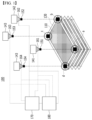
- the stacking inspection apparatus 100 is a stacking inspection apparatus 100 that inspects the alignment state of electrode plates 110 and 120 when the first electrode plate 110 and the second electrode plate 120 are stacked so that a separator 130 is interposed between the first electrode plate 110 and the second electrode plate 120 .
- the stacking inspection apparatus 100 includes camera units 141, 142, 143 and 144 that generate an aligned image by photographing four corner points a, b, c and d of the outer periphery of the first electrode plate110 or the second electrode plate 120 at an upper part in a stacking direction of the first electrode plate 110 and the second electrode plate 120; and light irradiation units 151, 152, 153 and 154 that irradiate light signals to four corner points of the first electrode plate 110 and the second electrode plate 120 as inspection objects at the upper part of the first electrode plate 110 or the second electrode plate 120, when the first electrode plate 110 and the second electrode plate 120 are stacked, wherein the camera units 141, 142, 143 and 144 include sensors 161, 162, 163 and 164 that recognize the light signal irradiated from the light irradiation units 151, 152, 153 and 154 and determine whether alignment of the first electrode plate 110 and the second electrode plate 120 is defective.
- the sensors 161, 162, 163 and 164 may inform an operator of this visually or audibly.
- the alignment correction can be automated by the control unit 180, the alignment correction can be performed in real time.
- the present disclosure since it is possible to determine in real time whether or not the electrode plates 110 and 120 are aligned each time they are stacked, it is possible to produce a product that is more aligned than before. Further, since the time required for the cathode-anode interval inspection performed at the time of product production in the past can be shortened, the product quality and yield can be improved.
- the sensors 161, 162, 163 and 164 can further measure the reciprocating time of the light signal irradiated from the light irradiation units 151, 152, 153, and 154. That is, the sensors 161, 162, 163, and 164 can measure the time when the light signal is recognized again from the time when the light signal is irradiated in connection with the light irradiation units 151, 152, 153 and 154, and the time (S1+ S2, S3+S3) when the light signal starts from the light irradiation units 151, 152, 153 and 154, reaches the electrode plate 110, and is recognized by the sensors 161, 162, 163, and 164 again, as shown in Fig. 2 .
- a difference may occur between the four corner points a, b, c and d until the light signal is recognized again, from which the thickness at each position of the electrode plates can be estimated.
- the measurement unit 170 stores information about the distance between the light irradiation units 151, 152, 153 and 154 for each stacking and the electrode plate located at the outermost shell at each stacking, and calculates the interval after the new electrode plate is stacked from the reciprocating time of the light signal, whereby the thickness of the newly stacked electrode plate can be measured from [the distance between the outermost electrode plate and the light irradiation units 151, 152, 153 and 154 before stacking - the distance between the outermost electrode plate and the light irradiation units 151, 152, 153 and 154 after stacking new electrode plates].
- Figs. 3 and 4 schematically show side views of the stacking inspection apparatuses 200 and 300 for such unit cells.
- the unit cells 210, 220 and 230 are stacked in the form of winding in one direction such that a separation film 240 is interposed between the one or more unit cells 210, 220 and 230, thereby manufacturing an electrode assembly.
- the stacking inspection apparatus may further include a measuring unit 280 that measures the thickness according to the position of each of the unit cells 210, 220 and 230 from the reciprocating time of each light signal measured from the sensors 271 and 272.
- the stacking inspection apparatus may further include a control unit 290 that corrects the alignment value according to information received from the sensors 271 and 272 and instructs the correction of the stacking position of the unit cells 210, 220 and 230 when the sensors 271 and 272 have determined to be alignment defects, and determines to be defective when the reciprocating time difference of each light signal measured from the sensors 271 and 272 is equal to or greater than a certain value, or when the thickness deviation depending on the position of each of the unit cells 210, 220 and 230 measured from the measurement unit 280 is equal to or greater than a certain value.
- a control unit 290 that corrects the alignment value according to information received from the sensors 271 and 272 and instructs the correction of the stacking position of the unit cells 210, 220 and 230 when the sensors 271 and 272 have determined to be alignment defects, and determines to be defective when the reciprocating time difference of each light signal measured from the sensors 271 and 272 is equal to or greater than a certain value, or when the thickness deviation depending on the position
- the thickness is different from that of the stacking inspection apparatus 100 of Fig. 1 in that the thickness of the unit cells 210, 220 and 230 is measured.
- Fig. 3 shows only a format in which the unit cells 210, 220 and 230 are wound in one direction, but it goes without saying that the stacking inspection apparatus 200 according to the present disclosure can be applied even when the separation film is stacked in a form in which unit cells are folded in a zigzag manner.
- an electrode assembly is manufactured in such a manner that a separator 340 is stacked in a form of interposing and stacking between one or more unit cells 310, 320 and 330.
- the sensors 371 and 372 can measure the reciprocating time of the light signal irradiated from the light irradiation units 361 and 362, and the stacking inspection apparatus 300 may further include a measuring unit 380 that measures the thickness according to the position of each of the unit cells 310, 320 and 330 from the reciprocating time of each light signal measured from the sensors 371 and 372.
- the stacking inspection apparatus may further include a control unit 390 that corrects the alignment value according to information received from the sensors 371 and 372 and instructs the correction of the stacking position of the unit cells 310, 320 and 330 when the sensors 371 and 372 have determined to be alignment defects, and determines to be defective when the reciprocating time difference of each light signal measured from the sensors 271 and 272 is equal to or greater than a certain value, or when the thickness deviation depending on the position of each of the unit cells 310, 320 and 330 measured from the measurement unit 380 is equal to or greater than a certain value.
- a control unit 390 that corrects the alignment value according to information received from the sensors 371 and 372 and instructs the correction of the stacking position of the unit cells 310, 320 and 330 when the sensors 371 and 372 have determined to be alignment defects, and determines to be defective when the reciprocating time difference of each light signal measured from the sensors 271 and 272 is equal to or greater than a certain value, or when the thickness deviation depending on the position
- the stacking inspection apparatus can inspect the stacking alignment defects of the electrode plates or the unit cells in real time by adding a light irradiation unit for irradiating a light signal to the apparatus used in the existing process, and adding a sensor to a camera.
- the time required for alignment inspection or interval inspection between cathode and anode during production can be reduced, and alignment defects can also be drastically reduced, so that the product performance can be enhanced, thus improving the product quality and improving the yield.
- the thickness difference at each position of the electrode plates or unit cells can be measured through the light irradiation unit used in the stacking inspection apparatus, it is possible to detect a loading defect, etc. with a large thickness deviation at each position. Therefore, it is possible to minimize errors that appear when an operator directly measures it, and it is possible to detect and remove electrode plates or unit cells having loading defects or thickness defects in advance, thus further improving the product quality.
Landscapes
- Chemical & Material Sciences (AREA)
- Engineering & Computer Science (AREA)
- Manufacturing & Machinery (AREA)
- Chemical Kinetics & Catalysis (AREA)
- Electrochemistry (AREA)
- General Chemical & Material Sciences (AREA)
- Physics & Mathematics (AREA)
- General Physics & Mathematics (AREA)
- Health & Medical Sciences (AREA)
- Life Sciences & Earth Sciences (AREA)
- Analytical Chemistry (AREA)
- Biochemistry (AREA)
- General Health & Medical Sciences (AREA)
- Immunology (AREA)
- Pathology (AREA)
- Secondary Cells (AREA)
Description
- This application claims the benefit of
Korean Patent Application No. 10-2021-0074998 filed on June 9, 2021 - The present disclosure relates to a stacking inspection apparatus for electrode plates or unit cells.
- Due to the rapid increase in the use of fossil fuels, the demand for the use of alternative energy or clean energy is increasing, and as part thereof, the fields that are being studied most actively are the fields of power generation and power storage using electrochemistry.
- At present, a secondary battery is a representative example of an electrochemical device that utilizes such electrochemical energy, and the range of use thereof tends to be gradually expanding.
- In recent years, as mobile devices, such as portable computers, portable phones, and cameras, have been increasingly developed, the demand for secondary batteries has also sharply increased as an energy source for the mobile devices. Among such secondary batteries is a lithium secondary battery exhibiting high charge/discharge characteristics and lifetime characteristics and being environmentally friendly, in which much research has been carried out and which is now commercialized and widely used.
- In addition, as interest in environmental issues grows, studies are frequently conducted on an electric vehicle, a hybrid electric vehicle, etc. which can replace a vehicle using fossil fuels such as a gasoline vehicle and a diesel vehicle, which are one of the main causes of air pollution. Although a nickel metal hydride secondary battery is mainly used as a power source for the electric vehicle and the hybrid electric vehicle, research on the use of a lithium secondary battery having high energy density and discharge voltage is actively being conducted, a part of which are in the commercialization stage.
- Such a lithium secondary battery is manufactured by forming an electrode assembly through a stacking process of a cathode and an anode, and incorporating the electrode assembly in a secondary battery case together with an electrolytic solution.
- At this time, the stacking process of the cathode and the anode is performed in various ways. The stacking is performed in the form of simply interposing a separator between the cathode and the anode, or is performed by manufacturing mono-cell containing a cathode and a separator or an anode and a separator, bi-cell containing a cathode, an anode and a separator, with electrodes of the same polarity being arranged on the outermost shell on both sides, or full-cell containing a cathode, an anode and a separator, with electrodes of different polarities being arranged in the outermost shell on both sides, folding or stacking them, followed by lamination.
- In this case, such a stacking process is one of the processes that can affect the performance of the secondary battery in the future, wherein the cathode and the anode must be aligned and stacked in a symmetrical state without twisting up, down, left and right.
- First, even in any case, when a cathode and an anode are stacked, twisting up, down, left and right between the cathode and the anode may occur, and thus, stacking alignment of the cathode and the anode itself is required. In addition, stacking alignment is also required during folding of unit cells, such as mono-cell, bi-cell, and full-cell, including electrodes and separators, and during stacking between these unit cells in the stacking process.
- Particularly, since the folding process of the unit cells winds the unit cells placed on the separator, it can be excellent in terms of process speed, but problems such as the tab interval of each electrode and twisting up, down, left and right are frequently occurred. This can be a major factor affecting the life and safety testing in the future because the interval between the cathode and the anode can be reversed.
- In order to improve these points, attempts have been made to improve ACOH by advancing the process of stacking and crimping unit cells, but when the number of stacked unit cells increases, there is a limit to the alignment of the unit cells inside and outside the electrode assembly. Thus, when adjusting the production conditions, there is a problem that a large number of unit cells are expressed as loss, which causes a problem of lowering the yield.
- Therefore, there is an urgent need to develop a technique that can solve the above problems and eliminate stacking alignment defects due to twisting up, down, left and right when stacking electrodes and unit cells, thereby enabling improvement of the quality and yield.
-
US 2019/341658 A1 describes a system and a method for electrode plate aligned state inspection. - The present disclosure has been designed to solve the above-mentioned problems and other technical problems that have yet to be resolved.
- Specifically, it is an object of the present disclosure to provide a stacking inspection apparatus that enables improvement of the product quality and the yield by determining stacking alignment defects in real time without major equipment changes in the existing process.
- It is another object of the present disclosure to provide a stacking inspection apparatus that can measure the vertical thickness difference based on the tab formation direction of the electrodes or unit cells through the stacking testing apparatus, minimize the error caused when an operator manually measures the thickness difference, thereby enabling further improvement of the product quality.
- In order to achieve the above objects, according to one embodiment of the present disclosure, there is provided a stacking inspection apparatus according to claim 1 for electrode plates when a first electrode plate and a second electrode plate are stacked so that a separator is interposed between the first electrode plate and the second electrode plate, the apparatus comprising inter alia:
- camera units that generate an aligned image by photographing four corner points of the outer periphery of the first electrode plate or the second electrode plate at an upper part in a stacking direction of the first electrode plate and the second electrode plate; and
- light irradiation units that irradiate a light signal to four corner points of the first electrode plate and the second electrode plate as inspection objects at the upper part of the first electrode plate or the second electrode plate when the first electrode plate and the second electrode plate are stacked,
- wherein the camera units comprises sensors that recognize the light signal irradiated from the light irradiation units and determine whether or not alignment of the first electrode plate and the second electrode plate is defective.
- In this case, the light irradiation units may irradiate the light signal so that the light signal passes when the first electrode plate or the second electrode plate is partially deviated even in any of left/right/upper/lower directions at the position where the first electrode plate or the second electrode plate should be stacked.
- And, the sensors recognize the light signal irradiated from the light irradiation units, and may determine to be alignment defects when at least one light signal passes through the four corner points.
- Further, the sensors measure the reciprocating time of the light signal irradiated from the light irradiation units.
- Moreover, the stacking inspection apparatus may further include a measuring unit that measures the thickness according to the position of each of the first electrode plate or the second electrode plate from the reciprocating time of each light signal measured from the sensors.
- Furthermore, the stacking inspection apparatus may further include a control unit that corrects the alignment value according to information received from the sensors and instructs the correction of the stacking position of the first electrode plate or the second electrode plate when the sensors determine to be alignment defects, and determines to be defective when the reciprocating time difference of each light signal measured from the sensors is equal to or greater than a certain value, or when the thickness deviation depending on the position of each of the first electrode plate or the second electrode plate measured from the measurement unit is equal to or greater than a certain value.
- According to another embodiment of the present disclosure, there is provided a stacking inspection apparatus according to claim 6 for unit cells when the unit cells are stacked so that a separation film or a separator is interposed between one or more unit cells, the apparatus comprising inter alia:
- camera units that generate an aligned image by photographing four corner points of the outer periphery of the unit cells at an upper part in a stacking direction of the unit cells; and
- light irradiation units that irradiate a light signal to four corner points of the unit cells as inspection objects at the upper part of the unit cells when the unit cells are stacked,
- wherein the camera units comprises sensors that recognize the light signal irradiated from the light irradiation units and determine whether or not alignment of the unit cells is defective.
- That is, not only the alignment of the electrode plates but also the alignment of the unit cells can be inspected.
- In this case, the light irradiation units may irradiate the light signal so that the light signal passes when the unit cells are partially deviated even in any of left/right/upper/lower directions at the position where the unit cells should be stacked, and the sensors recognize the light signal irradiated from the light irradiation units, and may determine to be alignment defects when at least one light signal passes through the four corner points.
- Further, the sensors measure the reciprocating time of the light signal irradiated from the light irradiation units, and the stacking inspection apparatus may further include a measuring unit that measures the thickness according to the position of each of the unit cells from the reciprocating time of each light signal measured from the sensor.
- Moreover, the stacking inspection apparatus may further include a control unit that corrects the alignment value according to information received from the sensors and instructs the correction of the stacking position of the unit cells when the sensors have determined to be alignment defects, and determines to be defective when the reciprocating time difference of each light signal measured from the sensors is equal to or greater than a certain value, or when the thickness deviation depending on the position of each of the unit cells measured from the measurement unit is equal to or greater than a certain value.
- The unit cells to which such a stacking inspection apparatus is applied may be stacked in such a manner that the separation film winds the unit cells in one direction, or may be stacked in such a manner that the separation film folds the unit cells in a zigzag, or may be stacked in such a manner that the separator is interposed between the unit cells and laminated.
-
-
Fig. 1 is a perspective view schematically showing a stacking inspection apparatus according to an embodiment of the present disclosure; -
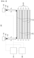
Fig. 2 is a schematic diagram showing a side view of the stacking inspection apparatus ofFig. 1 ; -
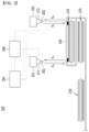
Fig. 3 is a schematic diagram showing a side view of a stacking inspection apparatus according to another embodiment of the present disclosure; and -
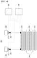
Fig. 4 is a schematic diagram showing a side view of a stacking inspection apparatus according to another embodiment of the present disclosure. - Hereinafter, the present disclosure will be described in more detail for a better understanding of the present disclosure.
- Terms or words used in the present specification and claims should not be construed as limited to ordinary or dictionary terms, and the present disclosure should be construed with meanings and concepts that are consistent with the technical idea of the present disclosure based on the principle that the inventors may appropriately define concepts of the terms to appropriately describe their own disclosure in the best way.
- The technical terms provided herein is merely used for the purpose of describing particular embodiments only, and is not intended to be limiting of the present disclosure. The singular forms include the plural forms as well, unless the context clearly indicates otherwise.
- The term "including" or "comprising" as used herein specifies a specific feature, integer, step, action, component or a combination thereof, but does not exclude the presence or addition of a different specific feature, integer, step, component and/or a combination thereof.
- According to one embodiment of the present disclosure, there is provided a stacking inspection apparatus for electrode plates when a first electrode plate and a second electrode plate are stacked so that a separator is interposed between the first electrode plate and the second electrode plate, the apparatus comprising:
- camera units that generate an aligned image by photographing four corner points of the outer periphery of the first electrode plate or the second electrode plate at an upper part in a stacking direction of the first electrode plate and the second electrode plate; and
- light irradiation units that irradiate a light signal to four corner points of the first electrode plate and the second electrode plate as inspection objects at the upper part of the first electrode plate or the second electrode plate when the first electrode plate and the second electrode plate are stacked,
- wherein the camera units comprises sensors that recognize the light signal irradiated from the light irradiation units and determine whether or not alignment of the first electrode plate and the second electrode plate is defective.
- Now, the present disclosure will be described in detail with reference to
Figs. 1 and2 . -
Fig. 1 is a perspective view schematically showing astacking inspection apparatus 100 according to an embodiment of the present disclosure, andFig. 2 schematically shows a side view of thestacking inspection apparatus 100 ofFig. 1 . - Referring to
Figs. 1 and2 together, thestacking inspection apparatus 100 according to an embodiment of the present disclosure is astacking inspection apparatus 100 that inspects the alignment state ofelectrode plates first electrode plate 110 and thesecond electrode plate 120 are stacked so that aseparator 130 is interposed between thefirst electrode plate 110 and thesecond electrode plate 120 . - The
stacking inspection apparatus 100 includescamera units second electrode plate 120 at an upper part in a stacking direction of thefirst electrode plate 110 and thesecond electrode plate 120; andlight irradiation units first electrode plate 110 and thesecond electrode plate 120 as inspection objects at the upper part of thefirst electrode plate 110 or thesecond electrode plate 120, when thefirst electrode plate 110 and thesecond electrode plate 120 are stacked, wherein thecamera units sensors light irradiation units first electrode plate 110 and thesecond electrode plate 120 is defective. - At this time, the
light irradiation units first electrode plate 110 or thesecond electrode plate 120 is partially deviated even in any of left/right/upper/lower directions at the position where the plates should be stacked. - In
Figs. 1 and2 , the light signal is irradiated so as not to deviate from the corners of theelectrode plates electrode plates sensors light irradiation units - At this time, the
sensors - The stacking
inspection apparatus 100 of the present disclosure may further include acontrol unit 180 that corrects the alignment value according to information received from thesensors first electrode plate 110 or thesecond electrode plate 120 when thesensors - That is, since the alignment correction can be automated by the
control unit 180, the alignment correction can be performed in real time. - Therefore, according to the present disclosure, since it is possible to determine in real time whether or not the
electrode plates - Meanwhile, the
sensors light irradiation units sensors light irradiation units light irradiation units electrode plate 110, and is recognized by thesensors Fig. 2 . - In this case, a difference may occur between the four corner points a, b, c and d until the light signal is recognized again, from which the thickness at each position of the electrode plates can be estimated.
- Alternatively, the stacking inspection apparat100 may further include a measuring
unit 170 that measures the thickness according to the position of each of thefirst electrode plate 110 or thesecond electrode plate 130 from the reciprocating time(S1+ S2, S3+S3) of each light signal measured from thesensors - Specifically, the
measurement unit 170 stores information about the distance between thelight irradiation units light irradiation units light irradiation units - Meanwhile, the
control unit 180 described above can determine to be defective when the reciprocating time difference (|S1+S2 -(S3+S4)|) of each light signal measured from thesensors first electrode plate 110 or thesecond electrode plate 120 measured from themeasurement unit 170 is equal to or greater than a certain value. - Therefore, as described above, when measuring the thickness at each position of the electrode plates, not only alignment defects, but also the loading deviation within one electrode plate, which appears due to the actual coating process characteristics can be measured in real time. Further, electrode plates with a large loading deviation depending on the position can be determined to be defective and can be removed in real time, thereby improving the product quality. In addition, conventionally, there has been a problem that an error occurs between workers when the worker measures the thickness of the electrode plate. However, by automating and mechanizing them, a product determined to be a uniform standard can be obtained, and thus, the reliability can be increased.
- According to another embodiment of the present disclosure, there is provided a stacking inspection apparatus for unit cells when the unit cells are stacked so that a separation film or a separator is interposed between one or more unit cells, the apparatus comprising:
- camera units that generate an aligned image by photographing four corner points of the outer periphery of the unit cells at an upper part in a stacking direction of the unit cells; and
- light irradiation units that irradiate a light signal to four corner points of the unit cells as inspection objects at the upper part of the unit cells,
- wherein the camera units comprises sensors that recognize the light signal irradiated from the light irradiation units and determine whether or not alignment of the unit cells is defective.
-
Figs. 3 and4 schematically show side views of the stackinginspection apparatuses - First, referring to
Fig. 3 , theunit cells separation film 240 is interposed between the one ormore unit cells - At this time, the stacking
inspection apparatus 200 according to the present invention includescamera units Fig. 1 at an upper part in a stacking direction of theunit cells light irradiation units unit cells unit cells unit cells camera units sensors light irradiation units unit cells - The
sensors light irradiation units - At this time, the roles of the
camera units light irradiation units respective sensors Figs. 1 and2 , and the difference is that the inspection objects are theunit cells - Further, the same applies to the measurement of the reciprocating time of the light signal irradiated from the
light irradiation units sensors unit 280 that measures the thickness according to the position of each of theunit cells sensors - Further, the stacking inspection apparatus may further include a
control unit 290 that corrects the alignment value according to information received from thesensors unit cells sensors sensors unit cells measurement unit 280 is equal to or greater than a certain value. - In this case, the thickness is different from that of the stacking
inspection apparatus 100 ofFig. 1 in that the thickness of theunit cells - Currently, in the electrode assembly manufacturing apparatus, there is no apparatus capable of filtering out defects in the thickness part after manufacture of the unit cells and stacking or lamination process of the unit cells, and thus, there is a risk of incorporation of products with high thickness. According to the present disclosure, since the thickness of the
unit cells -
Fig. 3 shows only a format in which theunit cells inspection apparatus 200 according to the present disclosure can be applied even when the separation film is stacked in a form in which unit cells are folded in a zigzag manner. - Additionally, referring to
Fig. 4 , an electrode assembly is manufactured in such a manner that aseparator 340 is stacked in a form of interposing and stacking between one ormore unit cells - At this time, the stacking
inspection apparatus 300 according to the present disclosure may further includecamera units Fig. 1 at an upper part in a stacking direction of theunit cells light irradiation units unit cells unit cells unit cells camera units sensors 371 and 372 that recognizes the light signal irradiated from thelight irradiation units unit cells - The
sensors 371 and 372 can measure the reciprocating time of the light signal irradiated from thelight irradiation units inspection apparatus 300 may further include a measuringunit 380 that measures the thickness according to the position of each of theunit cells sensors 371 and 372. - The stacking inspection apparatus may further include a
control unit 390 that corrects the alignment value according to information received from thesensors 371 and 372 and instructs the correction of the stacking position of theunit cells sensors 371 and 372 have determined to be alignment defects, and determines to be defective when the reciprocating time difference of each light signal measured from thesensors unit cells measurement unit 380 is equal to or greater than a certain value. - Those of ordinary skill in the art will be able to make various applications and modifications within the scope of the present disclosure based on the above contents.
-
- 100, 200, 300: stacking inspection apparatus,
- 110: first electrode plate, 120: second electrode plate,
- 130, 340: separator,
- 210, 220, 230, 310, 320, 330: unit cell,
- 240: separation film,
- 141, 142, 143, 144, 251, 252, 351, 352: camera unit;
- 151, 152, 153, 154, 261, 262, 361, 362: light irradiation unit;
- 161, 162, 163, 164, 271, 272, 371, 372: sensor,
- 170, 280, 380: measuring unit;
- 180, 290, 390: control unit.
- As described above, the stacking inspection apparatus according to an embodiment of the present disclosure can inspect the stacking alignment defects of the electrode plates or the unit cells in real time by adding a light irradiation unit for irradiating a light signal to the apparatus used in the existing process, and adding a sensor to a camera.
- Therefore, without affecting the existing process flow, the time required for alignment inspection or interval inspection between cathode and anode during production can be reduced, and alignment defects can also be drastically reduced, so that the product performance can be enhanced, thus improving the product quality and improving the yield.
- In addition, since the thickness difference at each position of the electrode plates or unit cells can be measured through the light irradiation unit used in the stacking inspection apparatus, it is possible to detect a loading defect, etc. with a large thickness deviation at each position. Therefore, it is possible to minimize errors that appear when an operator directly measures it, and it is possible to detect and remove electrode plates or unit cells having loading defects or thickness defects in advance, thus further improving the product quality.
Claims (11)
- A stacking inspection apparatus (100; 200; 300) for electrode plates when a first electrode plate (110) and a second electrode plate (120) are stacked so that a separator (130; 340) is interposed between the first electrode plate (110) and the second electrode plate (120), the apparatus comprising:camera units (141; 142; 143; 144; 251; 252; 351; 352) that generate an aligned image by photographing four corner points of the outer periphery of the first electrode plate (110) or the second electrode plate (120) at an upper part in a stacking direction of the first electrode plate (110) and the second electrode plate (120); andlight irradiation units (151; 152; 153; 154; 261; 262; 361; 362) that irradiate a light signal to four corner points of the first electrode plate (110) and the second electrode plate (120) as inspection objects at the upper part of the first electrode plate (110) or the second electrode plate (120) when the first electrode plate (110) and the second electrode plate (120) are stacked,wherein each camera unit (141; 142; 143; 144; 251; 252; 351; 352) of the camera units (141; 142; 143; 144; 251; 252; 351; 352) comprises a sensor (161; 162; 163; 164; 271; 272; 371; 372),wherein the sensors (161; 162; 163; 164; 271; 272; 371; 372) recognize the light signal irradiated from the light irradiation units (151; 152; 153; 154; 261; 262; 361; 362), measure a reciprocating time of the light signal irradiated from the light irradiation units (151; 152; 153; 154; 261; 262; 361; 362), and determine whether or not alignment of the first electrode plate (110) and the second electrode plate (120) is defective.
- The stacking inspection apparatus (100; 200; 300) of claim 1, wherein:
the light irradiation units (151; 152; 153; 154; 261; 262; 361; 362) irradiate the light signal so that the light signal passes through the four corner points when the first electrode plate (110) or the second electrode plate (120) is partially deviated even in any of left/right/upper/lower directions at the position where the plates should be stacked. - The stacking inspection apparatus (100; 200; 300) of claim 1 or 2, wherein:
the sensors (161; 162; 163; 164; 271; 272; 371; 372) determines alignment to be defective when at least one light signal passes through the four corner points. - The stacking inspection apparatus (100; 200; 300) of claim 1, further comprising:
a measuring unit (170; 280; 380) that measures the thickness according to the position of each of the first electrode plate (110) or the second electrode plate (120) from the reciprocating time of each light signal measured from the sensors (161; 162; 163; 164; 271; 272; 371; 372). - The stacking inspection apparatus (100; 200; 300) of claim 4, wherein:
the stacking inspection apparatus (100; 200; 300) further comprises a control unit (180; 290; 390) that corrects the alignment value according to information received from the sensors (161; 162; 163; 164; 271; 272; 371; 372) and instructs the correction of the stacking position of the first electrode plate (110) or the second electrode plate (120) when the sensors (161; 162; 163; 164; 271; 272; 371; 372) determine alignment to be defective, and determines alignment to be defective when the reciprocating time difference of each light signal measured from the sensors (161; 162; 163; 164; 271; 272; 371; 372) is equal to or greater than a certain value, or when the thickness deviation depending on the position of each of the first electrode plate (110) or the second electrode plate (120) measured from the measurement unit is equal to or greater than a certain value. - A stacking inspection apparatus (100; 200; 300) for unit cells (210; 220; 230; 310; 320; 330) when the unit cells (210; 220; 230; 310; 320; 330) are stacked so that a separation film (240) or a separator (130; 340) is interposed between one or more unit cells (210; 220; 230; 310; 320; 330), the apparatus comprising:camera units (141; 142; 143; 144; 251; 252; 351; 352) that generate an aligned image by photographing four corner points of the outer periphery of the unit cells (210; 220; 230; 310; 320; 330) at an upper part in a stacking direction of the unit cells (210; 220; 230; 310; 320; 330); andlight irradiation units that irradiate a light signal to four corner points of the unit cells (210; 220; 230; 310; 320; 330) as inspection objects at the upper part of the unit cells (210; 220; 230; 310; 320; 330) when the unit cells (210; 220; 230; 310; 320; 330) are stacked,wherein each camera unit (141; 142; 143; 144; 251; 252; 351; 352) of the camera units (141; 142; 143; 144; 251; 252; 351; 352) comprises a sensor,wherein the sensors (161; 162; 163; 164; 271; 272; 371; 372) recognize the light signal irradiated from the light irradiation units (151; 152; 153; 154; 261; 262; 361; 362), measure a reciprocating time of the light signal irradiated from the light irradiation units (151; 152; 153; 154; 261; 262; 361; 362), and determine whether or not alignment of the unit cells (210; 220; 230; 310; 320; 330) is defective.
- The stacking inspection apparatus (100; 200; 300) of claim 6, wherein:
the light irradiation units (151; 152; 153; 154; 261; 262; 361; 362) irradiate the light signal so that the light signal passes through the four corner points when the unit cells (210; 220; 230; 310; 320; 330) are partially deviated even in any of left/right/upper/lower directions at the position where the unit cells (210; 220; 230; 310; 320; 330) should be stacked. - The stacking inspection apparatus (100; 200; 300) of claim 6 or 7, wherein:
the sensors (161; 162; 163; 164; 271; 272; 371; 372) determine alignment to be defective when at least one light signal passes through the four corner points. - The stacking inspection apparatus (100; 200; 300) of claim 6, further comprising:
a measuring unit (170; 280; 380) that measures the thickness according to the position of each of the unit cells (210; 220; 230; 310; 320; 330) from the reciprocating time of each light signal measured from the sensors (161; 162; 163; 164; 271; 272; 371; 372). - The stacking inspection apparatus (100; 200; 300) of claim 9, wherein:
The stacking inspection apparatus (100; 200; 300) further comprises a control unit (180; 290; 390) that corrects the alignment value according to information received from the sensors (161; 162; 163; 164; 271; 272; 371; 372) and instructs the correction of the stacking position of the unit cells (210; 220; 230; 310; 320; 330) when the sensors (161; 162; 163; 164; 271; 272; 371; 372) determine alignment to be defective, and determines alignment to be defective when the reciprocating time difference of each light signal measured from the sensors (161; 162; 163; 164; 271; 272; 371; 372) is equal to or greater than a certain value, or when the thickness deviation depending on the position of each of the unit cells (210; 220; 230; 310; 320; 330) measured from the measurement unit is equal to or greater than a certain value. - The stacking inspection apparatus (100; 200; 300) of claim 6, wherein:
the unit cells (210; 220; 230; 310; 320; 330) are stacked in such a manner that the separation film (240) winds the unit cells (210; 220; 230; 310; 320; 330) in one direction, or are stacked in such a manner that the separation film (240) folds the unit cells (210; 220; 230; 310; 320; 330) in a zigzag, or are stacked in such a manner that the separator (130; 340) is interposed between the unit cells (210; 220; 230; 310; 320; 330) and laminated.
Applications Claiming Priority (2)
| Application Number | Priority Date | Filing Date | Title |
|---|---|---|---|
| KR1020210074998A KR102821620B1 (en) | 2021-06-09 | 2021-06-09 | Stacking ispection apparatus for electrode plate or unit cell |
| PCT/KR2022/003218 WO2022260245A1 (en) | 2021-06-09 | 2022-03-07 | Stacking inspection apparatus for electrode plate or unit cell |
Publications (3)
| Publication Number | Publication Date |
|---|---|
| EP4123778A1 EP4123778A1 (en) | 2023-01-25 |
| EP4123778A4 EP4123778A4 (en) | 2023-09-06 |
| EP4123778B1 true EP4123778B1 (en) | 2024-07-03 |
Family
ID=84047773
Family Applications (1)
| Application Number | Title | Priority Date | Filing Date |
|---|---|---|---|
| EP22758110.5A Active EP4123778B1 (en) | 2021-06-09 | 2022-03-07 | Stacking inspection apparatus for electrode plate or unit cell |
Country Status (7)
| Country | Link |
|---|---|
| US (1) | US20240183789A1 (en) |
| EP (1) | EP4123778B1 (en) |
| KR (1) | KR102821620B1 (en) |
| CN (1) | CN115943510A (en) |
| ES (1) | ES2989965T3 (en) |
| HU (1) | HUE067986T2 (en) |
| WO (1) | WO2022260245A1 (en) |
Families Citing this family (7)
| Publication number | Priority date | Publication date | Assignee | Title |
|---|---|---|---|---|
| EP4369292B1 (en) * | 2022-04-08 | 2025-12-17 | Contemporary Amperex Technology (Hong Kong) Limited | Displacement detection method and apparatus, delivery apparatus, and storage medium |
| CN117053730B (en) * | 2023-10-11 | 2024-02-02 | 杭州睿影科技有限公司 | Detection method and device for laminated battery, image processing equipment and medium |
| DE102023128068A1 (en) * | 2023-10-13 | 2025-04-17 | Körber Technologies Gmbh | Measuring device and measuring method for determining at least one property of a flat element in the battery cell producing industry |
| KR20250114764A (en) * | 2024-01-22 | 2025-07-29 | 주식회사 엘지에너지솔루션 | secondary cell stacking apparatus and a contorl method of the same |
| CN118004618B (en) * | 2024-02-27 | 2026-01-06 | 布勒(无锡)商业有限公司 | Multifunctional auxiliary systems and methods for integrated information-based container areas |
| WO2026005562A1 (en) * | 2024-06-27 | 2026-01-02 | 주식회사 엘지에너지솔루션 | Unit cell inspection device and unit cell inspection method using same |
| KR20260021403A (en) * | 2024-08-06 | 2026-02-13 | 주식회사 엘지에너지솔루션 | Electrode alignnment vision inspection apparatus |
Family Cites Families (13)
| Publication number | Priority date | Publication date | Assignee | Title |
|---|---|---|---|---|
| KR102042467B1 (en) * | 2016-03-04 | 2019-11-08 | 주식회사 엘지화학 | Device for Measuring Thickness of Battery Cell Comprising Laser Sensor and Method for Measuring Thickness of Battery Cell Using the Same |
| US10293547B2 (en) * | 2016-06-07 | 2019-05-21 | Xerox Corporation | Electrostatic 3-D printer using layer and mechanical planer |
| KR102255705B1 (en) * | 2016-07-26 | 2021-05-26 | 엘지전자 주식회사 | Cell lamination and thermocompression bonding device, and cell lamination and thermocompression bonding method |
| CN106586138B (en) * | 2017-02-28 | 2022-06-03 | 江苏创源电子有限公司 | Automatic detection material receiving equipment and automatic packaging machine |
| KR101992467B1 (en) * | 2017-11-07 | 2019-06-24 | (주)피토 | An electrode plate transfer apparatrus of a secondary battery manufacturing apparatus including an electrode plate inspection function |
| CN207595135U (en) * | 2017-12-07 | 2018-07-10 | 安徽拜客科技有限公司 | A kind of shared bicycle night riding safety alarming device |
| WO2019160305A1 (en) * | 2018-02-13 | 2019-08-22 | 주식회사 이노메트리 | High-speed stack manufacturing apparatus for secondary battery |
| KR102629119B1 (en) * | 2018-05-02 | 2024-01-26 | 에스케이온 주식회사 | Electrode plate position inspection system and inspection method |
| KR102177841B1 (en) * | 2018-11-22 | 2020-11-11 | 주식회사 강한이노시스 | Apparatus for Monitoring Electrode Film Stacking of Secondary Battery Using Lighting |
| KR102107226B1 (en) | 2018-12-20 | 2020-05-07 | 김태완 | Alignment inspection device for stacked battery |
| KR102904508B1 (en) * | 2019-01-11 | 2025-12-30 | 한국전자통신연구원 | X-ray inspection device |
| CN110861811A (en) * | 2019-12-18 | 2020-03-06 | 广东省智能机器人研究院 | Full-automatic detection and packaging system and detection and packaging method for circular dinner plate |
| CN112660686B (en) * | 2021-03-17 | 2021-06-01 | 杭州蓝芯科技有限公司 | Depth camera-based material cage stacking method and device, electronic equipment and system |
-
2021
- 2021-06-09 KR KR1020210074998A patent/KR102821620B1/en active Active
-
2022
- 2022-03-07 US US17/915,403 patent/US20240183789A1/en active Pending
- 2022-03-07 WO PCT/KR2022/003218 patent/WO2022260245A1/en not_active Ceased
- 2022-03-07 ES ES22758110T patent/ES2989965T3/en active Active
- 2022-03-07 HU HUE22758110A patent/HUE067986T2/en unknown
- 2022-03-07 EP EP22758110.5A patent/EP4123778B1/en active Active
- 2022-03-07 CN CN202280003003.3A patent/CN115943510A/en active Pending
Also Published As
| Publication number | Publication date |
|---|---|
| KR102821620B1 (en) | 2025-06-16 |
| CN115943510A (en) | 2023-04-07 |
| US20240183789A1 (en) | 2024-06-06 |
| KR20220166098A (en) | 2022-12-16 |
| WO2022260245A1 (en) | 2022-12-15 |
| EP4123778A1 (en) | 2023-01-25 |
| ES2989965T3 (en) | 2024-11-28 |
| HUE067986T2 (en) | 2024-12-28 |
| EP4123778A4 (en) | 2023-09-06 |
Similar Documents
| Publication | Publication Date | Title |
|---|---|---|
| EP4123778B1 (en) | Stacking inspection apparatus for electrode plate or unit cell | |
| EP3565052B1 (en) | Electrode plate aligned state inspection system and method | |
| US11372052B2 (en) | Jig pressing-type pressing short-circuiting inspection method | |
| JP5583480B2 (en) | Inspection method for lithium ion secondary battery | |
| KR102940143B1 (en) | A system for inspecting a defect in a battery cell and a method for inspecting a defect in a battery cell | |
| KR102624807B1 (en) | Electrode assembly and inspecting method for the same | |
| KR101558250B1 (en) | Fixation Device for Checking Defect of Electrode Assembly and Method of Checking the Same | |
| KR20220111363A (en) | Method and device for evaluating core deformation degree of cylindrical battery cell | |
| KR20120096621A (en) | Methode and device for inspection of intensity of ultrasonic welding | |
| KR20130124098A (en) | Method for preparing bi-cell | |
| KR20200059483A (en) | Pressure short testing device for detecting a low voltage battery cell | |
| KR20200059559A (en) | Degas system for secondary cell | |
| KR20220118250A (en) | Device and method for detecting damage to monocell type separator | |
| EP4372855A1 (en) | Manufacturing method of electrode assembly | |
| KR20220138739A (en) | Method for detecting abnormal battery through relative comparison | |
| EP4113696A1 (en) | System for detecting defect of electrode tab and method for detecting defect of electrode tab by using same | |
| US11841328B2 (en) | Method and device for testing electrode sheet | |
| KR20200059560A (en) | Rolling module for secondary battery cell | |
| JP7011782B2 (en) | Secondary battery inspection method | |
| KR102479303B1 (en) | Jig press apparatus | |
| EP4249904B1 (en) | Device and method for detecting internal defect of battery cell by using tdr | |
| KR102950058B1 (en) | Method for managing quality of battery cell and system for managing quality of battery cell | |
| EP4700328A1 (en) | Defect inspection device and defect inspection method | |
| KR102952010B1 (en) | Stack cell for being easy to identification of separator, separator inspection apparatus and method thereof | |
| KR20260056599A (en) | Electrode assembly and method for manufacturing same |
Legal Events
| Date | Code | Title | Description |
|---|---|---|---|
| STAA | Information on the status of an ep patent application or granted ep patent |
Free format text: STATUS: UNKNOWN |
|
| STAA | Information on the status of an ep patent application or granted ep patent |
Free format text: STATUS: THE INTERNATIONAL PUBLICATION HAS BEEN MADE |
|
| PUAI | Public reference made under article 153(3) epc to a published international application that has entered the european phase |
Free format text: ORIGINAL CODE: 0009012 |
|
| STAA | Information on the status of an ep patent application or granted ep patent |
Free format text: STATUS: REQUEST FOR EXAMINATION WAS MADE |
|
| 17P | Request for examination filed |
Effective date: 20220901 |
|
| AK | Designated contracting states |
Kind code of ref document: A1 Designated state(s): AL AT BE BG CH CY CZ DE DK EE ES FI FR GB GR HR HU IE IS IT LI LT LU LV MC MK MT NL NO PL PT RO RS SE SI SK SM TR |
|
| REG | Reference to a national code |
Ref country code: DE Ref legal event code: R079 Free format text: PREVIOUS MAIN CLASS: H01M0010040000 Ipc: G01B0011260000 Ref country code: DE Ref legal event code: R079 Ref document number: 602022004367 Country of ref document: DE Free format text: PREVIOUS MAIN CLASS: H01M0010040000 Ipc: G01B0011260000 |
|
| A4 | Supplementary search report drawn up and despatched |
Effective date: 20230804 |
|
| RIC1 | Information provided on ipc code assigned before grant |
Ipc: G01N 21/95 20060101ALI20230731BHEP Ipc: G01B 11/06 20060101ALI20230731BHEP Ipc: H01M 10/04 20060101ALI20230731BHEP Ipc: G01B 11/26 20060101AFI20230731BHEP |
|
| GRAP | Despatch of communication of intention to grant a patent |
Free format text: ORIGINAL CODE: EPIDOSNIGR1 |
|
| STAA | Information on the status of an ep patent application or granted ep patent |
Free format text: STATUS: GRANT OF PATENT IS INTENDED |
|
| DAV | Request for validation of the european patent (deleted) | ||
| DAX | Request for extension of the european patent (deleted) | ||
| INTG | Intention to grant announced |
Effective date: 20240409 |
|
| RIC1 | Information provided on ipc code assigned before grant |
Ipc: H01M 10/0585 20100101ALI20240322BHEP Ipc: G01N 21/95 20060101ALI20240322BHEP Ipc: H01M 10/04 20060101ALI20240322BHEP Ipc: G01B 11/06 20060101ALI20240322BHEP Ipc: G01B 11/26 20060101AFI20240322BHEP |
|
| GRAS | Grant fee paid |
Free format text: ORIGINAL CODE: EPIDOSNIGR3 |
|
| GRAA | (expected) grant |
Free format text: ORIGINAL CODE: 0009210 |
|
| STAA | Information on the status of an ep patent application or granted ep patent |
Free format text: STATUS: THE PATENT HAS BEEN GRANTED |
|
| AK | Designated contracting states |
Kind code of ref document: B1 Designated state(s): AL AT BE BG CH CY CZ DE DK EE ES FI FR GB GR HR HU IE IS IT LI LT LU LV MC MK MT NL NO PL PT RO RS SE SI SK SM TR |
|
| REG | Reference to a national code |
Ref country code: CH Ref legal event code: EP |
|
| REG | Reference to a national code |
Ref country code: DE Ref legal event code: R096 Ref document number: 602022004367 Country of ref document: DE |
|
| P01 | Opt-out of the competence of the unified patent court (upc) registered |
Free format text: CASE NUMBER: APP_41107/2024 Effective date: 20240711 |
|
| REG | Reference to a national code |
Ref country code: LT Ref legal event code: MG9D |
|
| REG | Reference to a national code |
Ref country code: NL Ref legal event code: MP Effective date: 20240703 |
|
| REG | Reference to a national code |
Ref country code: ES Ref legal event code: FG2A Ref document number: 2989965 Country of ref document: ES Kind code of ref document: T3 Effective date: 20241128 |
|
| PG25 | Lapsed in a contracting state [announced via postgrant information from national office to epo] |
Ref country code: PT Free format text: LAPSE BECAUSE OF FAILURE TO SUBMIT A TRANSLATION OF THE DESCRIPTION OR TO PAY THE FEE WITHIN THE PRESCRIBED TIME-LIMIT Effective date: 20241104 |
|
| REG | Reference to a national code |
Ref country code: AT Ref legal event code: MK05 Ref document number: 1700223 Country of ref document: AT Kind code of ref document: T Effective date: 20240703 |
|
| PG25 | Lapsed in a contracting state [announced via postgrant information from national office to epo] |
Ref country code: NL Free format text: LAPSE BECAUSE OF FAILURE TO SUBMIT A TRANSLATION OF THE DESCRIPTION OR TO PAY THE FEE WITHIN THE PRESCRIBED TIME-LIMIT Effective date: 20240703 |
|
| REG | Reference to a national code |
Ref country code: HU Ref legal event code: AG4A Ref document number: E067986 Country of ref document: HU |
|
| PG25 | Lapsed in a contracting state [announced via postgrant information from national office to epo] |
Ref country code: PT Free format text: LAPSE BECAUSE OF FAILURE TO SUBMIT A TRANSLATION OF THE DESCRIPTION OR TO PAY THE FEE WITHIN THE PRESCRIBED TIME-LIMIT Effective date: 20241104 Ref country code: NL Free format text: LAPSE BECAUSE OF FAILURE TO SUBMIT A TRANSLATION OF THE DESCRIPTION OR TO PAY THE FEE WITHIN THE PRESCRIBED TIME-LIMIT Effective date: 20240703 |
|
| PG25 | Lapsed in a contracting state [announced via postgrant information from national office to epo] |
Ref country code: NO Free format text: LAPSE BECAUSE OF FAILURE TO SUBMIT A TRANSLATION OF THE DESCRIPTION OR TO PAY THE FEE WITHIN THE PRESCRIBED TIME-LIMIT Effective date: 20241003 |
|
| PG25 | Lapsed in a contracting state [announced via postgrant information from national office to epo] |
Ref country code: GR Free format text: LAPSE BECAUSE OF FAILURE TO SUBMIT A TRANSLATION OF THE DESCRIPTION OR TO PAY THE FEE WITHIN THE PRESCRIBED TIME-LIMIT Effective date: 20241004 Ref country code: FI Free format text: LAPSE BECAUSE OF FAILURE TO SUBMIT A TRANSLATION OF THE DESCRIPTION OR TO PAY THE FEE WITHIN THE PRESCRIBED TIME-LIMIT Effective date: 20240703 Ref country code: PL Free format text: LAPSE BECAUSE OF FAILURE TO SUBMIT A TRANSLATION OF THE DESCRIPTION OR TO PAY THE FEE WITHIN THE PRESCRIBED TIME-LIMIT Effective date: 20240703 |
|
| PG25 | Lapsed in a contracting state [announced via postgrant information from national office to epo] |
Ref country code: BG Free format text: LAPSE BECAUSE OF FAILURE TO SUBMIT A TRANSLATION OF THE DESCRIPTION OR TO PAY THE FEE WITHIN THE PRESCRIBED TIME-LIMIT Effective date: 20240703 |
|
| PG25 | Lapsed in a contracting state [announced via postgrant information from national office to epo] |
Ref country code: LV Free format text: LAPSE BECAUSE OF FAILURE TO SUBMIT A TRANSLATION OF THE DESCRIPTION OR TO PAY THE FEE WITHIN THE PRESCRIBED TIME-LIMIT Effective date: 20240703 |
|
| PG25 | Lapsed in a contracting state [announced via postgrant information from national office to epo] |
Ref country code: AT Free format text: LAPSE BECAUSE OF FAILURE TO SUBMIT A TRANSLATION OF THE DESCRIPTION OR TO PAY THE FEE WITHIN THE PRESCRIBED TIME-LIMIT Effective date: 20240703 Ref country code: IS Free format text: LAPSE BECAUSE OF FAILURE TO SUBMIT A TRANSLATION OF THE DESCRIPTION OR TO PAY THE FEE WITHIN THE PRESCRIBED TIME-LIMIT Effective date: 20241103 |
|
| PG25 | Lapsed in a contracting state [announced via postgrant information from national office to epo] |
Ref country code: HR Free format text: LAPSE BECAUSE OF FAILURE TO SUBMIT A TRANSLATION OF THE DESCRIPTION OR TO PAY THE FEE WITHIN THE PRESCRIBED TIME-LIMIT Effective date: 20240703 Ref country code: CZ Free format text: LAPSE BECAUSE OF FAILURE TO SUBMIT A TRANSLATION OF THE DESCRIPTION OR TO PAY THE FEE WITHIN THE PRESCRIBED TIME-LIMIT Effective date: 20240703 |
|
| PG25 | Lapsed in a contracting state [announced via postgrant information from national office to epo] |
Ref country code: RS Free format text: LAPSE BECAUSE OF FAILURE TO SUBMIT A TRANSLATION OF THE DESCRIPTION OR TO PAY THE FEE WITHIN THE PRESCRIBED TIME-LIMIT Effective date: 20241003 |
|
| PG25 | Lapsed in a contracting state [announced via postgrant information from national office to epo] |
Ref country code: RS Free format text: LAPSE BECAUSE OF FAILURE TO SUBMIT A TRANSLATION OF THE DESCRIPTION OR TO PAY THE FEE WITHIN THE PRESCRIBED TIME-LIMIT Effective date: 20241003 Ref country code: PL Free format text: LAPSE BECAUSE OF FAILURE TO SUBMIT A TRANSLATION OF THE DESCRIPTION OR TO PAY THE FEE WITHIN THE PRESCRIBED TIME-LIMIT Effective date: 20240703 Ref country code: NO Free format text: LAPSE BECAUSE OF FAILURE TO SUBMIT A TRANSLATION OF THE DESCRIPTION OR TO PAY THE FEE WITHIN THE PRESCRIBED TIME-LIMIT Effective date: 20241003 Ref country code: LV Free format text: LAPSE BECAUSE OF FAILURE TO SUBMIT A TRANSLATION OF THE DESCRIPTION OR TO PAY THE FEE WITHIN THE PRESCRIBED TIME-LIMIT Effective date: 20240703 Ref country code: IS Free format text: LAPSE BECAUSE OF FAILURE TO SUBMIT A TRANSLATION OF THE DESCRIPTION OR TO PAY THE FEE WITHIN THE PRESCRIBED TIME-LIMIT Effective date: 20241103 Ref country code: HR Free format text: LAPSE BECAUSE OF FAILURE TO SUBMIT A TRANSLATION OF THE DESCRIPTION OR TO PAY THE FEE WITHIN THE PRESCRIBED TIME-LIMIT Effective date: 20240703 Ref country code: GR Free format text: LAPSE BECAUSE OF FAILURE TO SUBMIT A TRANSLATION OF THE DESCRIPTION OR TO PAY THE FEE WITHIN THE PRESCRIBED TIME-LIMIT Effective date: 20241004 Ref country code: FI Free format text: LAPSE BECAUSE OF FAILURE TO SUBMIT A TRANSLATION OF THE DESCRIPTION OR TO PAY THE FEE WITHIN THE PRESCRIBED TIME-LIMIT Effective date: 20240703 Ref country code: CZ Free format text: LAPSE BECAUSE OF FAILURE TO SUBMIT A TRANSLATION OF THE DESCRIPTION OR TO PAY THE FEE WITHIN THE PRESCRIBED TIME-LIMIT Effective date: 20240703 Ref country code: BG Free format text: LAPSE BECAUSE OF FAILURE TO SUBMIT A TRANSLATION OF THE DESCRIPTION OR TO PAY THE FEE WITHIN THE PRESCRIBED TIME-LIMIT Effective date: 20240703 Ref country code: AT Free format text: LAPSE BECAUSE OF FAILURE TO SUBMIT A TRANSLATION OF THE DESCRIPTION OR TO PAY THE FEE WITHIN THE PRESCRIBED TIME-LIMIT Effective date: 20240703 |
|
| REG | Reference to a national code |
Ref country code: DE Ref legal event code: R097 Ref document number: 602022004367 Country of ref document: DE |
|
| PG25 | Lapsed in a contracting state [announced via postgrant information from national office to epo] |
Ref country code: DK Free format text: LAPSE BECAUSE OF FAILURE TO SUBMIT A TRANSLATION OF THE DESCRIPTION OR TO PAY THE FEE WITHIN THE PRESCRIBED TIME-LIMIT Effective date: 20240703 Ref country code: RO Free format text: LAPSE BECAUSE OF FAILURE TO SUBMIT A TRANSLATION OF THE DESCRIPTION OR TO PAY THE FEE WITHIN THE PRESCRIBED TIME-LIMIT Effective date: 20240703 Ref country code: SM Free format text: LAPSE BECAUSE OF FAILURE TO SUBMIT A TRANSLATION OF THE DESCRIPTION OR TO PAY THE FEE WITHIN THE PRESCRIBED TIME-LIMIT Effective date: 20240703 |
|
| PG25 | Lapsed in a contracting state [announced via postgrant information from national office to epo] |
Ref country code: EE Free format text: LAPSE BECAUSE OF FAILURE TO SUBMIT A TRANSLATION OF THE DESCRIPTION OR TO PAY THE FEE WITHIN THE PRESCRIBED TIME-LIMIT Effective date: 20240703 |
|
| PG25 | Lapsed in a contracting state [announced via postgrant information from national office to epo] |
Ref country code: SK Free format text: LAPSE BECAUSE OF FAILURE TO SUBMIT A TRANSLATION OF THE DESCRIPTION OR TO PAY THE FEE WITHIN THE PRESCRIBED TIME-LIMIT Effective date: 20240703 Ref country code: IT Free format text: LAPSE BECAUSE OF FAILURE TO SUBMIT A TRANSLATION OF THE DESCRIPTION OR TO PAY THE FEE WITHIN THE PRESCRIBED TIME-LIMIT Effective date: 20240703 |
|
| PLBE | No opposition filed within time limit |
Free format text: ORIGINAL CODE: 0009261 |
|
| STAA | Information on the status of an ep patent application or granted ep patent |
Free format text: STATUS: NO OPPOSITION FILED WITHIN TIME LIMIT |
|
| 26N | No opposition filed |
Effective date: 20250404 |
|
| PGFP | Annual fee paid to national office [announced via postgrant information from national office to epo] |
Ref country code: ES Payment date: 20250408 Year of fee payment: 4 |
|
| PG25 | Lapsed in a contracting state [announced via postgrant information from national office to epo] |
Ref country code: SE Free format text: LAPSE BECAUSE OF FAILURE TO SUBMIT A TRANSLATION OF THE DESCRIPTION OR TO PAY THE FEE WITHIN THE PRESCRIBED TIME-LIMIT Effective date: 20240703 |
|
| PG25 | Lapsed in a contracting state [announced via postgrant information from national office to epo] |
Ref country code: MC Free format text: LAPSE BECAUSE OF FAILURE TO SUBMIT A TRANSLATION OF THE DESCRIPTION OR TO PAY THE FEE WITHIN THE PRESCRIBED TIME-LIMIT Effective date: 20240703 |
|
| REG | Reference to a national code |
Ref country code: CH Ref legal event code: H13 Free format text: ST27 STATUS EVENT CODE: U-0-0-H10-H13 (AS PROVIDED BY THE NATIONAL OFFICE) Effective date: 20251023 |
|
| PG25 | Lapsed in a contracting state [announced via postgrant information from national office to epo] |
Ref country code: LU Free format text: LAPSE BECAUSE OF NON-PAYMENT OF DUE FEES Effective date: 20250307 |
|
| PG25 | Lapsed in a contracting state [announced via postgrant information from national office to epo] |
Ref country code: CH Free format text: LAPSE BECAUSE OF NON-PAYMENT OF DUE FEES Effective date: 20250331 |
|
| PG25 | Lapsed in a contracting state [announced via postgrant information from national office to epo] |
Ref country code: IE Free format text: LAPSE BECAUSE OF NON-PAYMENT OF DUE FEES Effective date: 20250307 |
|
| PGFP | Annual fee paid to national office [announced via postgrant information from national office to epo] |
Ref country code: GB Payment date: 20260224 Year of fee payment: 5 |
|
| PGFP | Annual fee paid to national office [announced via postgrant information from national office to epo] |
Ref country code: DE Payment date: 20260220 Year of fee payment: 5 |
|
| PGFP | Annual fee paid to national office [announced via postgrant information from national office to epo] |
Ref country code: BE Payment date: 20260220 Year of fee payment: 5 |
|
| PGFP | Annual fee paid to national office [announced via postgrant information from national office to epo] |
Ref country code: HU Payment date: 20260310 Year of fee payment: 5 |
|
| PGFP | Annual fee paid to national office [announced via postgrant information from national office to epo] |
Ref country code: FR Payment date: 20260224 Year of fee payment: 5 |