EP4123771A2 - Elektrochemische anlage, die bei hohen temperaturen arbeitet, und entsprechendes verfahren - Google Patents
Elektrochemische anlage, die bei hohen temperaturen arbeitet, und entsprechendes verfahren Download PDFInfo
- Publication number
- EP4123771A2 EP4123771A2 EP22186158.6A EP22186158A EP4123771A2 EP 4123771 A2 EP4123771 A2 EP 4123771A2 EP 22186158 A EP22186158 A EP 22186158A EP 4123771 A2 EP4123771 A2 EP 4123771A2
- Authority
- EP
- European Patent Office
- Prior art keywords
- bay
- enclosure
- fluid
- self
- stack
- Prior art date
- Legal status (The legal status is an assumption and is not a legal conclusion. Google has not performed a legal analysis and makes no representation as to the accuracy of the status listed.)
- Pending
Links
Images



Classifications
-
- H—ELECTRICITY
- H01—ELECTRIC ELEMENTS
- H01M—PROCESSES OR MEANS, e.g. BATTERIES, FOR THE DIRECT CONVERSION OF CHEMICAL ENERGY INTO ELECTRICAL ENERGY
- H01M8/00—Fuel cells; Manufacture thereof
- H01M8/04—Auxiliary arrangements, e.g. for control of pressure or for circulation of fluids
- H01M8/04007—Auxiliary arrangements, e.g. for control of pressure or for circulation of fluids related to heat exchange
- H01M8/04067—Heat exchange or temperature measuring elements, thermal insulation, e.g. heat pipes, heat pumps, fins
-
- H—ELECTRICITY
- H01—ELECTRIC ELEMENTS
- H01M—PROCESSES OR MEANS, e.g. BATTERIES, FOR THE DIRECT CONVERSION OF CHEMICAL ENERGY INTO ELECTRICAL ENERGY
- H01M8/00—Fuel cells; Manufacture thereof
- H01M8/24—Grouping of fuel cells, e.g. stacking of fuel cells
- H01M8/2465—Details of groupings of fuel cells
- H01M8/247—Arrangements for tightening a stack, for accommodation of a stack in a tank or for assembling different tanks
- H01M8/2475—Enclosures, casings or containers of fuel cell stacks
-
- C—CHEMISTRY; METALLURGY
- C25—ELECTROLYTIC OR ELECTROPHORETIC PROCESSES; APPARATUS THEREFOR
- C25B—ELECTROLYTIC OR ELECTROPHORETIC PROCESSES FOR THE PRODUCTION OF COMPOUNDS OR NON-METALS; APPARATUS THEREFOR
- C25B5/00—Electrogenerative processes, i.e. processes for producing compounds in which electricity is generated simultaneously
-
- H—ELECTRICITY
- H01—ELECTRIC ELEMENTS
- H01M—PROCESSES OR MEANS, e.g. BATTERIES, FOR THE DIRECT CONVERSION OF CHEMICAL ENERGY INTO ELECTRICAL ENERGY
- H01M8/00—Fuel cells; Manufacture thereof
- H01M8/04—Auxiliary arrangements, e.g. for control of pressure or for circulation of fluids
- H01M8/04007—Auxiliary arrangements, e.g. for control of pressure or for circulation of fluids related to heat exchange
- H01M8/04014—Heat exchange using gaseous fluids; Heat exchange by combustion of reactants
-
- H—ELECTRICITY
- H01—ELECTRIC ELEMENTS
- H01M—PROCESSES OR MEANS, e.g. BATTERIES, FOR THE DIRECT CONVERSION OF CHEMICAL ENERGY INTO ELECTRICAL ENERGY
- H01M8/00—Fuel cells; Manufacture thereof
- H01M8/04—Auxiliary arrangements, e.g. for control of pressure or for circulation of fluids
- H01M8/04007—Auxiliary arrangements, e.g. for control of pressure or for circulation of fluids related to heat exchange
- H01M8/04037—Electrical heating
-
- H—ELECTRICITY
- H01—ELECTRIC ELEMENTS
- H01M—PROCESSES OR MEANS, e.g. BATTERIES, FOR THE DIRECT CONVERSION OF CHEMICAL ENERGY INTO ELECTRICAL ENERGY
- H01M8/00—Fuel cells; Manufacture thereof
- H01M8/04—Auxiliary arrangements, e.g. for control of pressure or for circulation of fluids
- H01M8/04082—Arrangements for control of reactant parameters, e.g. pressure or concentration
-
- H—ELECTRICITY
- H01—ELECTRIC ELEMENTS
- H01M—PROCESSES OR MEANS, e.g. BATTERIES, FOR THE DIRECT CONVERSION OF CHEMICAL ENERGY INTO ELECTRICAL ENERGY
- H01M8/00—Fuel cells; Manufacture thereof
- H01M8/10—Fuel cells with solid electrolytes
- H01M8/12—Fuel cells with solid electrolytes operating at high temperature, e.g. with stabilised ZrO2 electrolyte
-
- H—ELECTRICITY
- H01—ELECTRIC ELEMENTS
- H01M—PROCESSES OR MEANS, e.g. BATTERIES, FOR THE DIRECT CONVERSION OF CHEMICAL ENERGY INTO ELECTRICAL ENERGY
- H01M8/00—Fuel cells; Manufacture thereof
- H01M8/24—Grouping of fuel cells, e.g. stacking of fuel cells
- H01M8/2465—Details of groupings of fuel cells
- H01M8/2484—Details of groupings of fuel cells characterised by external manifolds
-
- H—ELECTRICITY
- H01—ELECTRIC ELEMENTS
- H01M—PROCESSES OR MEANS, e.g. BATTERIES, FOR THE DIRECT CONVERSION OF CHEMICAL ENERGY INTO ELECTRICAL ENERGY
- H01M8/00—Fuel cells; Manufacture thereof
- H01M8/24—Grouping of fuel cells, e.g. stacking of fuel cells
- H01M8/249—Grouping of fuel cells, e.g. stacking of fuel cells comprising two or more groupings of fuel cells, e.g. modular assemblies
-
- H—ELECTRICITY
- H01—ELECTRIC ELEMENTS
- H01M—PROCESSES OR MEANS, e.g. BATTERIES, FOR THE DIRECT CONVERSION OF CHEMICAL ENERGY INTO ELECTRICAL ENERGY
- H01M8/00—Fuel cells; Manufacture thereof
- H01M8/10—Fuel cells with solid electrolytes
- H01M8/12—Fuel cells with solid electrolytes operating at high temperature, e.g. with stabilised ZrO2 electrolyte
- H01M2008/1293—Fuel cells with solid oxide electrolytes
-
- H—ELECTRICITY
- H01—ELECTRIC ELEMENTS
- H01M—PROCESSES OR MEANS, e.g. BATTERIES, FOR THE DIRECT CONVERSION OF CHEMICAL ENERGY INTO ELECTRICAL ENERGY
- H01M8/00—Fuel cells; Manufacture thereof
- H01M8/10—Fuel cells with solid electrolytes
- H01M8/1016—Fuel cells with solid electrolytes characterised by the electrolyte material
- H01M8/1018—Polymeric electrolyte materials
- H01M8/1069—Polymeric electrolyte materials characterised by the manufacturing processes
- H01M8/1086—After-treatment of the membrane other than by polymerisation
- H01M8/109—After-treatment of the membrane other than by polymerisation thermal other than drying, e.g. sintering
-
- Y—GENERAL TAGGING OF NEW TECHNOLOGICAL DEVELOPMENTS; GENERAL TAGGING OF CROSS-SECTIONAL TECHNOLOGIES SPANNING OVER SEVERAL SECTIONS OF THE IPC; TECHNICAL SUBJECTS COVERED BY FORMER USPC CROSS-REFERENCE ART COLLECTIONS [XRACs] AND DIGESTS
- Y02—TECHNOLOGIES OR APPLICATIONS FOR MITIGATION OR ADAPTATION AGAINST CLIMATE CHANGE
- Y02E—REDUCTION OF GREENHOUSE GAS [GHG] EMISSIONS, RELATED TO ENERGY GENERATION, TRANSMISSION OR DISTRIBUTION
- Y02E60/00—Enabling technologies; Technologies with a potential or indirect contribution to GHG emissions mitigation
- Y02E60/30—Hydrogen technology
- Y02E60/50—Fuel cells
Definitions
- the present invention relates to an electrochemical installation, comprising a plurality of stacks for carrying out electrochemical reactions, in particular for the production of electricity, the production of gaseous compounds or co-electrolysis and a heating furnace comprising an enclosure intended to receiving the or each stack, and a heating system.
- This installation is intended to be located on land or at sea, for the production of electricity from fuels such as hydrogen, methane, propane, butane, fermentation gases, gasified biomass, biofuels and synthetic fuels, ammonia, methanol, carbon monoxide, natural gas or/and paint fumes.
- fuels such as hydrogen, methane, propane, butane, fermentation gases, gasified biomass, biofuels and synthetic fuels, ammonia, methanol, carbon monoxide, natural gas or/and paint fumes.
- the installation is intended for the production of a gaseous compound, for example hydrogen, from electricity produced for example by renewable electricity sources, in particular by wind turbines, or solar panels or more generally, by an electrical network.
- a gaseous compound for example hydrogen
- the installation is intended for the production of gaseous compounds by co-electrolysis, for example for the production of a synthesis gas intended for the synthesis of chemical constituents by electrolysis, from water and carbon dioxide.
- the installation comprises a plurality of stacks which are for example solid oxide electrolysis cells (or "SOEC” according to the acronym for “Solid Oxide Electrolysis Cells”) or solid oxide fuel cells (or SOFC” according to the English acronym of “Solid Oxide Fuel Cells”).
- SOEC solid oxide electrolysis cells
- SOFC solid oxide fuel cells
- the invention is also applicable to other high temperature fuel cell technologies (more than 100° C.).
- These batteries are intended primarily for stationary applications with an output power ranging from 1 kW to 20 MW.
- Their gaseous emissions can be used to power a secondary gas turbine to increase electrical efficiency.
- the gaseous discharges can also supply a catalytic burner generating steam that can be used or recovered directly. Water vapor is for example produced in order to increase the overall electrical efficiency of the system if this water vapor is used to produce additional electricity.
- a SOFC (or electrochemical cell) element usually consists of four layers, three of which are ceramics. It has a typical thickness of a few millimeters. Dozens or hundreds of these elements are then superimposed in series to form a stack or “pile” (or “stack”).
- the oxygen ions are moved through a solid oxide membrane taken as the electrolyte at high temperature, in order to react with the gaseous fuel, for example hydrogen, on the anode side.
- the ceramics used in SOFCs only become electrically and ionically active when they reach a very high temperature. Consequently, the stacks must reach temperatures of the order of 600° C. to 1,200° C. to form an active membrane.
- SOFCs or SOECs Due to the high operating temperature of SOFCs or SOECs, it is not necessary to provide an expensive catalyst (platinum for example), unlike fuel cells with a proton exchange membrane. This means that SOFCs or SOECs do not undergo catalytic poisoning by carbon monoxide, thus making them highly adaptable.
- Thermal expansion requires slow, uniform heating at its onset. Usually an hour or more of warming up is required.
- the stacks of fuel cells or electrolyser cells are integrated into a heat-insulated enclosure of a small furnace normally used for firing ceramics.
- the stacks are loaded individually into a heat-insulated enclosure and are placed at the bottom of the enclosure in fewer than four numbers. Utilities are associated with each enclosure and connected to each stack to supply the various fluids required and to recover the fluids produced. These utilities are called in English Balance Of Plant (BOP) and also allow the treatment of the gas as well as its temperature rise via heat recovery before reacting within the stacks.
- BOP English Balance Of Plant
- the enclosures cannot be positioned side-by-side in a compact manner, which implies the need for clearance zones, multi-stage structures, as well as the multiplication of pipes and isolation valves.
- An object of the invention is therefore to provide an electrochemical installation operating at high temperature, intended for example for the generation of electricity and/or gaseous compounds or for co-electrolysis, which is compact, while remaining reliable and simple to operate.
- the subject of the invention is an installation of the aforementioned type, characterized in that the installation comprises at least one bay, the or each bay comprising a self-supporting structure comprising several superimposed levels of stacks or/and the or each bay comprising several self-supporting structures defining several superposed levels of stacks, each self-supporting structure comprising a fluid distributor able to supply each stack with at least one fluid or/and to collect at least one fluid from each stack, the enclosure being capable of containing at least one bay, the stacking stages of the or each bay contained in the enclosure being intended to be heated jointly by the heating system.
- a first electrochemical installation 10 according to the invention intended in particular for the generation of electricity and/or for the production of gaseous compounds and/or for co-electrolysis is illustrated by the figures 1 to 5 .
- the installation 10 comprises a plurality of individual bays 12, each bay 12 carrying a plurality of stacks 14 for implementing electrochemical reactions, in particular for the production of electricity, the production of gaseous compounds or co-electrolysis .
- the generation installation 10 comprises at least one oven 16 intended to contain at least one bay 12, and to jointly heat the stacks 14 of the or each bay 12 contained in the oven 16.
- the generation installation 10 comprises a fluid distribution system 18 intended to be fluidically connected to each bay 12 received in a furnace 16.
- the installation 10 is intended to be placed on land or at sea, for example on a platform at sea. It rests on a ground or on a floor 19.
- Each stack 14 generally comprises a plurality of individual stacking elements, arranged one on top of the other.
- Each unitary element (or cell) comprises a first electrode, an electrolyte, in particular a solid electrolyte, and a second electrode of opposite polarity to the first electrode.
- the electrodes are for example formed of flat unitary elements, and the geometry of the stack 14 is then a geometry of the sandwich type.
- each electrode is formed of a tubular element, and the geometry of the stack 14 is then of the tubular type.
- each stack 14 comprises a first inlet 22 for supplying a first supply fluid, and a first outlet 24 for recovering a first fluid produced.
- the first input 22 and the first output 24 are in fluid communication with each first electrode of each unitary element contained in the stack 14.
- stack 14 includes a second inlet 26 for a second supply fluid and a second outlet 28 for recovering a second fluid produced.
- the second input 26 and the second output 28 are in fluid communication with each second electrode of each unitary element contained in the stack 14.
- the stack 14 is for example a solid oxide fuel cell (or “SOFC”, as defined above).
- the first electrode is an anode
- the first supply fluid is a fuel containing or consisting in particular of hydrogen, methane, propane, butane, fermentation gas, gasified biomass, biofuels and/or synthetic fuels, ammonia, methanol, carbon monoxide, natural gas and/or paint fumes.
- the first fluid produced is then generally water, carbon dioxide and sometimes includes an excess of unreacted fuel within the stack 14.
- the second electrode is a cathode.
- the second feed fluid is air.
- the second fluid produced is a remnant of oxygen-depleted air.
- the electrolyte acts as a membrane that separates the fuel on the anode side from the air on the cathode side. It is for example formed from ceramic material, for example based on zirconium oxide.
- a current of electrons is collected at the terminals of the electrodes of each unitary element to be supplied to an electrical network.
- the stack is a solid oxide electrolysis cell (“SOEC”, as defined above).
- SOEC solid oxide electrolysis cell
- the first feed fluid at the anode is air and the first fluid produced is oxygen.
- the second feed fluid at the cathode is water vapor, and the second fluid produced is hydrogen.
- the stack 14 is intended for the co-electrolysis of gaseous compounds, for example water vapor and carbon dioxide, to form for example a synthesis gas intended for the synthesis of chemical constituents.
- gaseous compounds for example water vapor and carbon dioxide
- the electrolysis reaction occurs under the effect of an electric current supplied to the terminals of the electrodes of each unitary element, from, for example, an electric network, and/or an installation for the production of electric energy.
- an electric current supplied to the terminals of the electrodes of each unitary element from, for example, an electric network, and/or an installation for the production of electric energy.
- a renewable electricity production installation comprising for example at least one wind turbine, at least one tidal turbine and/or at least one solar panel.
- the number of individual elements in each stack 14 is preferably greater than ten and is in particular between fifty and two hundred.
- the bay 12 is a self-supporting structure having several floors, individually movable and integral with respect to other other bays 12.
- the bay 12 is a stack of floors of self-supporting structures.
- Each self-supporting structure is capable of being introduced into the oven 16 and of being extracted from the oven 16 in one piece.
- a bay 12 comprising a self-supporting structure having two identical elementary floors is illustrated.
- Each self-supporting structure of a bay 12 carries a plurality of stacks 14 which are movable together with each other, independently of the stacks 14 present in other bays 12 contained in the oven 16 or, where appropriate, independently of the stacks 14 present in another freestanding structure in the same bay 12.
- Each self-supporting structure of a bay 12 further comprises a fluid distributor 30 specific to the self-supporting structure of the bay 12, intended to supply each stack 14 of the bay 12 with first supply fluid and second supply fluid, from the distribution system 18 common to all the bays 12 and to recover, from each stack 14 of the bay 12, the first fluid produced and the second fluid produced to bring them back to the distribution system 18 common to all the berries 12.
- each self-supporting structure of a bay 12 comprises more than four stacks 14, in particular a number of stacks 14 greater than or equal to eight, in particular greater than or equal to sixteen, advantageously between thirty-two and fifty-six.
- stacks 14 of each self-supporting structure of a bay 12 are for example organized on each floor in the form of rows 32A to 32D of stacks 14.
- At least two rows 32A, 32B are parallel, and are located side by side on the same floor, and at least two rows 32C, 32D, are located respectively above a row 32A, 32B on another floor of the bay 12.
- the stacks 14 located on one floor of a bay 12 are distinct and are spaced vertically from the stacks 14 located on another floor of the bay 12.
- the distributor 30 of each self-supporting structure of a bay 12 comprises a first common pipe 34 for supplying the first supply fluid, a first common pipe 36 for recovering the first fluid produced, a second common pipe 38 for supplying the second supply fluid, and a second common pipe 40 for recovering the second fluid produced, the common pipes 34 to 40 being intended to be connected to the system distribution 18.
- the distributor 30 further comprises a connection 44 to 50 specific to each row 32A to 32D to fluidically connect each common pipe 34 to 40 to each stack 14 arranged on a row 32A to 32D.
- the common lines 34 to 40 protrude parallel to each other beyond the stacks 14 and the branches 44 to 50. In this example, they extend horizontally.
- Each common pipe 34 to 40 has an end flange intended to be removably connected to the distribution system 18.
- the distribution flanges of at least four common pipes 34 to 40 of the same bay 12 are coplanar, and are located in a vertical plane perpendicular to the axis of each common pipe 34 to 40.
- branches 44 to 50 are rigid which all extend parallel to the respective common lines 34 to 40.
- Each branch 44 to 50 is connected to a respective common conduit 34 to 40 via one or more transverse branches.
- each connection 44 is connected on the one hand, to the first common pipe 34, and on the other hand, to the first inlets 22 for supplying the first supply fluid to each stack 14 of a row 32A to 32D, via a respective tapping.
- the common pipe 34 is therefore the only pipe supplying the first supply fluid to all the stacks 14 of the self-supporting structure of the bay 12.
- Each branch 46 is connected on the one hand to the first common pipe 36, and on the other hand to the first outlets 24 for recovering the first fluid produced from each stack 14 of a row 32A to 32D, via a respective tapping.
- the common pipe 36 is therefore the only pipe collecting the first fluid produced by all the stacks 14 of the self-supporting structure of the bay 12.
- Each branch 48 is connected on the one hand, to the second common pipe 38, and on the other hand, to the second inlets 26 for supplying the second supply fluid to each stack 14 of a row 32A to 32D, via a respective stitching.
- the common pipe 38 is therefore the only pipe supplying the second supply fluid to all the stacks 14 of the self-supporting structure of the bay 12.
- Each branch 50 is connected on the one hand to the second common pipe 40, and on the other hand to the second outlets 28 for recovering the second fluid produced from each stack 14 of a row 32A to 32D, via a respective tapping.
- the common pipe 40 is therefore the only pipe collecting the second fluid produced by all the stacks 14 of the self-supporting structure of the bay 12.
- connections 44 to 50 are flexible which are connected on the one hand, to at least one rigid clarinet connected to the common pipes 34 to 40 and on the other hand, respectively to the inputs 22, 26 and the outputs 24, 28 of each stack 14.
- each self-supporting structure of a bay 12 is movable in one piece between a normal operating position, placed in the oven 16, and a maintenance position, placed outside the oven 16.
- Each bay 12 does not have its own heating means.
- the stacks 14 of each self-supporting structure of each bay 12 are intended to be heated together with the stacks 14 of other bays 12 contained in the same oven 16 or, where applicable, with the stacks 14 of the other self-supporting structures of the same bay 12.
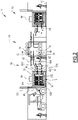
- the oven 16 comprises a heat-insulated enclosure 60, intended to simultaneously receive at least one bay 12 to allow the joint heating of the stacks 14 present on several floors, a system 62 for heating the enclosure 60, and a system for stirring air 64 (visible on the picture 2 ), to homogenize the temperature in the oven 16, in particular during the start-up phases and during the operating phases.
- the enclosure 60 is here formed by walls 65A to 65E delimiting an interior volume 66 parallelepipedic.
- the walls 65A to 65E are thermally insulated. They have, for example, a thermal conductivity of less than 0.5 W/m.K.
- the interior volume 66 of the enclosure 60 is capable of receiving at least one bay 12, in particular between one bay 12 and ten bays 12.
- the interior volume 66 of the enclosure 60 is thus capable of containing more than ten stacks 14, in particular more than 100 stacks, for example several hundred stacks 14.
- the interior volume of enclosure 60 is for example greater than 9 m 3 and is in particular between 9 m 3 and 100 m 3 .
- the free space not occupied by bays 12 in the interior volume 66 is greater than 50% of the volume of a bay 12 in order to be able to install in the enclosure 60, the heating system 62, the muffles (for example made of refractory steel) and the internal air circulation system as well as the pipes 34 to 40.
- the walls 65 comprise at least one side wall 65A placed facing the distribution system 18, and at least one side wall 65B, here advantageously provided with side doors 65C facing each bay 12, allowing access to the interior volume 66 for selectively inserting each bay 12 into interior volume 66 or extracting it from interior volume 66.
- the walls 65 also optionally comprise a lower wall 65D, and an upper wall 65E closing the interior volume 66 respectively upwards and downwards.
- the side wall 65A is provided with openings 68 for the passage of the common pipes 34 to 40, each opening 68 being capable of being crossed by a common pipe 34 to 40 respectively of a bay 12.
- each common pipe 34 to 40 of a self-supporting structure of a bay 12 protrudes out of the interior volume 66 towards the distribution system 18 through a respective opening 68 in side wall 65A to allow connection to distribution system 18.
- the passage openings 68 located opposite the bay 12 in its normal operating position are capable of being blocked by an insulating sleeve. thermally (not shown).
- the other self-supporting bay structures 12 placed in the interior volume 66 remain in normal operating position during maintenance of one of the self-supporting bay structures 12 extracted from the interior volume 66.
- the heating system 62 is suitable for heating the gaseous atmosphere within the interior volume 66 to bring this atmosphere to a temperature above 450° C., for example between 450° C. and 1300° C., in particular between 600° C. and 1200°C.
- the oven 16 comprises electrical resistors.
- the resistors are for example installed vertically between the heat-insulated enclosure 60 and the or each bay 12.
- the oven 16 then advantageously comprises a so-called “muffle” insulation plate.
- This plate protects the connectors of bay 12 from direct radiation. It is also possible to install a muffle/resistance/muffle system between bays 12 when they are side by side.
- the resistors provide rapid warming of the enclosure 60 for start-up and, if necessary, maintenance of the temperature in the event of endothermic operation of the stacks 14 (likely to occur in electrolysis mode).
- the feed fluids introduced into stack 14 are heated to maintain stack 14 at reaction temperature. electrolysis/co-electrolysis.
- each electrical resistor is inserted into at least one steel metal tube provided with through holes.
- This steel tube includes enough openings to allow the circulation of the internal atmosphere as well as heat exchanges.
- the electrical resistors are suitable for heating the entire interior volume 66 to simultaneously raise the temperature of each bay 12 contained in the interior volume 66, and each stack 14 contained in a bay 12.
- the heating system comprises at least one burner.
- the stirring system 64 is for example formed by stirrers, advantageously arranged in the upper wall 65E.
- the stirrers are suitable for stirring the gaseous atmosphere inside the interior volume 66 to improve the homogeneity of the heat exchanges. They are also suitable for being used to force a rapid and controlled cooling of the temperature of the interior volume 66 within the oven 16.
- the stirrers significantly improve heat transfer and significantly reduce heating and cooling times. They are capable of generating a circulation of gas in the atmosphere around the or each bay 12.
- Each stirrer comprises a rotary stirring member, carrying at least one blade and a motor for driving the movable member in rotation.
- the stirrer is preferably mounted in a wall of the enclosure 60, the motor being located outside the interior volume 66 and the rotary stirring member being placed in the interior volume 66.
- the stirring system 64 is associated with a system (not shown) for injecting neutral gas (for example nitrogen) and possibly with an on-line analyzer capable of detecting any presence of hydrogen on a flow of taken out of the oven 16.
- neutral gas for example nitrogen
- the sweep ensures an overpressure in the interior volume 66 of the enclosure 60.
- the overpressure also limits the risk of the stacks 14 leaking.
- the tightness of the furnace 16 is also maximized to reduce the heat losses inherent in sweeping and/or stirring.
- the mixing system 64 allowing a homogenization of the temperature within the entire interior volume 66, it authorizes the operation in parallel in the same enclosure 66 of several bays 12 or, if necessary of several floors of self-supporting structures of the same bay 12.
- the stirring avoids the appearance of hot spots within the oven 16 and therefore a significant increase in temperature (for example more than 10% compared to the average temperature of the stacks 14) of certain stacks 14 compared to others.
- the temperature of the various stacks 14 being constant and homogeneous, the risk of breakage of the stacks 14, and significant disparities in the rate of use of the stacks 14 is limited.
- the lifetimes of all the stacks 14 contained within the interior volume 66 are therefore homogeneous.
- the arrangement of the stacks 14 in the form of bays 12 within the interior volume 66 of the oven 16, and the pooling of the power supply to each bay 12 outside the oven 16 by the distribution system 18 optimizes the space within the interior volume 66 so that it is occupied almost exclusively by bays 12.
- heat exchanges can occur within the interior volume 66 between the different common pipes 34 to 40, and between the different connections 44 to 50. This simplifies the implementation of the method, and eliminates dedicated heat exchanges for this implementation, particularly the most expensive exchangers operating at the highest temperature of the system.
- the distribution system 18 comprises a conduit 70 for supplying the first supply fluid, a conduit 72 for discharging the first fluid produced, a conduit 74 for supplying the second supply fluid, and a conduit 76 for evacuation of second fluid produced.
- the distribution system 18 further comprises, associated with each bay 12, tappings 80 to 86 respectively connected to each conduit 70 to 76, each tapping 80 to 86 being provided with a respective connection valve (vir 82A, 86A on the picture 2 ) to connect each respective conduit 70 to 76 to a respective common conduit 34 to 40 of each bay 12.
- At least one group of conduits 70 to 76 is associated with each oven 16 to be connected to each bay 12 contained in the oven 16.
- two ovens 16 are arranged parallel to each other, each oven 16 being provided with a shared distribution system 18 for the two ovens.
- the ducts 70 to 76 extend parallel to a longitudinal axis AA' of the oven 16, along and facing the side wall 65A.
- tappings 80 to 86 protrude transversely with respect to the axis A-A', towards the wall 65A, outside the latter.
- At least part of the free ends of the tappings 80 to 86 are located in the same vertical plane parallel to the axis A-A'.
- the free ends of the common pipes 34 to 40 are able to be removably connected to the free ends of the tappings 80 to 86 when the or each bay 12 is located in the interior volume 66 of the enclosure 60, the common pipes 34 to 40 projecting through the side openings 68.
- connections between the taps 80 to 86 and each bay 12 are easily accessible so that they can be checked and easily disconnected if a bay 12 or, where applicable, a self-supporting structure of a bay 12 must be moved outside the interior volume 66 of an oven 16.
- the arrangement of the conduits 70 to 76 parallel to the axis A-A' of the furnace 16 further increases the compactness of the installation 10, while maintaining easy access to the connections.
- the capacity of the installation 10 in the production of electricity and/or in the production of fuel fluid is increased.
- the size of the installation 10 is reduced.
- each bay 12 or each free-standing structure of bay 12 is placed in the interior volume 66 of the oven 16, for example using a forklift 90, as illustrated in the figure 4 .
- each bay 12 or each bay freestanding structure 12 Upon placement of each bay 12 or each bay freestanding structure 12 at a location in the interior volume 66, the side door 65C is opened, and the bay or the bay freestanding structure 12 is advanced towards the side wall 65A by making pass the common lines 34 to 40 through the respective openings 68.
- the heating system 62 is activated, by supplying the electrical resistors to bring the gaseous atmosphere inside the interior volume 66 to a temperature greater than 450° C., in particular between 450° C. and 1300° C., for example between 600°C and 1200°C.
- Progressive and joint heating supported by the mixing of the internal atmosphere of the plurality of bays 12, or where applicable, of each self-supporting structure of a bay 12 and of each stack 14 contained in the or in each bay 12 is thus obtained. very simply.
- the valves on the respective taps 80 to 86 are open.
- the first supply fluid flows from the supply conduit 70 through each tapping 80 to the first common pipe 34 of each bay 12, then through each branch 44 of the bay 12. It then enters each stack 14 via first inlet 22 connected to branch 44.
- the first supply fluid reacts on the first electrode, generating a first product fluid.
- the first fluid produced is collected in each first outlet 24, then is collected in a branch 46, before reaching the first common pipe 36. Then, the first fluid produced is evacuated through the evacuation duct 72 via the tapping 82 .
- the second supply fluid flows from the supply pipe 74 through each tapping 84 to the second common pipe 38 of each bay 12, then through each branch 48 of the bay 12. It enters then in each stack 14 via the second input 26 connected to the connection 48.
- the second feed fluid reacts on the second electrode, producing a second product fluid.
- the second fluid produced is discharged through the second outlet 28, then via a branch 50 to the second common pipe 40. It is then collected in the evacuation pipe 76 via the tapping 86.
- the door 65C located opposite this bay 12 is open.
- valves 80A to 86A connected to this bay 12 are closed, and the free ends of the pipes 34 to 40 of the bay 12 are disconnected from the taps 80 to 86.
- the bay 12 or, where applicable, the self-supporting structure of the bay 12 is then removed from the interior volume 66, without having to move other bays 12 or, where applicable, other self-supporting structures of the bay 12 and is brought in its maintenance position outside the interior volume 66.
- the bay 12 or, if applicable, the self-supporting structure of the bay 12 can be put back in place at the same location, once the maintenance has been carried out, or alternatively, be replaced by another bay 12 or, if necessary, by another self-supporting structure of bay 12.
- each bay 12 is then movable through the upper wall 65E by means of a traveling crane 92, after possible dismantling of the connection pipes ("spool") of the system of distribution 18 located above enclosure 60.
- the traveling crane 92 comprises a horizontal beam 94 located above the furnace 16, and a winch 96 mounted to move along the beam 94, transversely relative to the axis A-A' of the furnace 16.
- the brewing system 64 is for example installed under the or each bay 12.
- the enclosure 60 is raised in order to locate the motors of the brewers under the enclosure 60.
- this installation variant 10 is moreover similar to that of the installation 10 represented on the figures 1 to 5 .
- the ducts 70 to 76 of the distribution system 18 are located under the oven 16, the openings 68 then being formed in a floor 65D of the enclosure 60,
Landscapes
- Chemical & Material Sciences (AREA)
- Engineering & Computer Science (AREA)
- Electrochemistry (AREA)
- Chemical Kinetics & Catalysis (AREA)
- Manufacturing & Machinery (AREA)
- Sustainable Development (AREA)
- Sustainable Energy (AREA)
- Life Sciences & Earth Sciences (AREA)
- General Chemical & Material Sciences (AREA)
- Combustion & Propulsion (AREA)
- Materials Engineering (AREA)
- Metallurgy (AREA)
- Organic Chemistry (AREA)
- Physical Or Chemical Processes And Apparatus (AREA)
- Fuel Cell (AREA)
- Electrolytic Production Of Non-Metals, Compounds, Apparatuses Therefor (AREA)
Applications Claiming Priority (1)
| Application Number | Priority Date | Filing Date | Title |
|---|---|---|---|
| FR2107954A FR3125650B1 (fr) | 2021-07-22 | 2021-07-22 | Installation électrochimique opérant à haute température et procédé associé |
Publications (2)
| Publication Number | Publication Date |
|---|---|
| EP4123771A2 true EP4123771A2 (de) | 2023-01-25 |
| EP4123771A3 EP4123771A3 (de) | 2023-04-12 |
Family
ID=78086464
Family Applications (1)
| Application Number | Title | Priority Date | Filing Date |
|---|---|---|---|
| EP22186158.6A Pending EP4123771A3 (de) | 2021-07-22 | 2022-07-21 | Elektrochemische anlage, die bei hohen temperaturen arbeitet, und entsprechendes verfahren |
Country Status (8)
| Country | Link |
|---|---|
| US (1) | US12355117B2 (de) |
| EP (1) | EP4123771A3 (de) |
| JP (1) | JP7803807B2 (de) |
| KR (1) | KR20230015291A (de) |
| CN (1) | CN115692766A (de) |
| AU (1) | AU2022206788A1 (de) |
| CA (1) | CA3168428A1 (de) |
| FR (1) | FR3125650B1 (de) |
Families Citing this family (7)
| Publication number | Priority date | Publication date | Assignee | Title |
|---|---|---|---|---|
| KR20230107140A (ko) * | 2022-01-07 | 2023-07-14 | 블룸 에너지 코퍼레이션 | 모듈형 전해조 시스템 |
| AT527216B1 (de) * | 2023-08-01 | 2024-12-15 | Avl List Gmbh | Zellenstapelsystem für ein Brennstoffzellensystem |
| AT527881A1 (de) * | 2024-05-08 | 2025-06-15 | Avl List Gmbh | Aufnahmevorrichtung für eine Aufnahme von Stapelmodulen mit gestapelten Brennstoffzellen eines Brennstoffzellensystems |
| AT528323B1 (de) * | 2024-05-28 | 2026-02-15 | Avl List Gmbh | Boxermodul für ein elektrochemisches Zellensystem |
| EP4703499A1 (de) * | 2024-08-30 | 2026-03-04 | L'air Liquide, Societe Anonyme Pour L'etude Et L'exploitation Des Procedes Georges Claude | Elektrolyseanordnung |
| DE102024209054A1 (de) * | 2024-09-20 | 2026-03-26 | Siemens Energy Global GmbH & Co. KG | Verbessertes Modul für Elektrolyseanlage |
| GB202414141D0 (en) * | 2024-09-26 | 2024-11-13 | Ceres Power Ltd | Electrolyser system |
Family Cites Families (9)
| Publication number | Priority date | Publication date | Assignee | Title |
|---|---|---|---|---|
| CA2482486A1 (en) * | 2004-09-24 | 2006-03-24 | British Columbia Hydro And Power Authority | Fuel cell power generation system |
| US7691502B2 (en) * | 2005-03-15 | 2010-04-06 | Jadoo Power Systems, Inc. | Modular fuel cell power system, and technique for controlling and/or operating same |
| TW200917559A (en) * | 2007-10-15 | 2009-04-16 | Nan Ya Printed Circuit Board Corp | Fuel cell system |
| US8153326B2 (en) * | 2008-04-01 | 2012-04-10 | Commscope, Inc. Of North Carolina | Electronics cabinet with air feed and exhaust system for backup power fuel cell |
| JP5451808B2 (ja) * | 2012-04-02 | 2014-03-26 | 京セラ株式会社 | 燃料電池組立体 |
| JP2015082478A (ja) * | 2013-10-24 | 2015-04-27 | 株式会社ノーリツ | 燃料電池発電モジュール |
| US9608284B2 (en) * | 2014-07-30 | 2017-03-28 | Microsoft Technology Licensing, Llc | Dynamically controlled heat exchange for cascading startup of fuel cell grids |
| US10886553B2 (en) * | 2016-12-19 | 2021-01-05 | Vionx Energy Corporation | Large scale flow battery system |
| TWI797216B (zh) * | 2017-12-15 | 2023-04-01 | 美商博隆能源股份有限公司 | 具有共同入口充氣部及共同出口充氣部的可堆疊燃料電池發電機配置 |
-
2021
- 2021-07-22 FR FR2107954A patent/FR3125650B1/fr active Active
-
2022
- 2022-07-21 EP EP22186158.6A patent/EP4123771A3/de active Pending
- 2022-07-21 AU AU2022206788A patent/AU2022206788A1/en active Pending
- 2022-07-21 CA CA3168428A patent/CA3168428A1/fr active Pending
- 2022-07-22 US US17/871,207 patent/US12355117B2/en active Active
- 2022-07-22 JP JP2022117413A patent/JP7803807B2/ja active Active
- 2022-07-22 KR KR1020220090962A patent/KR20230015291A/ko active Pending
- 2022-07-22 CN CN202210875301.3A patent/CN115692766A/zh active Pending
Also Published As
| Publication number | Publication date |
|---|---|
| FR3125650A1 (fr) | 2023-01-27 |
| JP7803807B2 (ja) | 2026-01-21 |
| EP4123771A3 (de) | 2023-04-12 |
| KR20230015291A (ko) | 2023-01-31 |
| FR3125650B1 (fr) | 2023-07-28 |
| US12355117B2 (en) | 2025-07-08 |
| JP2023017735A (ja) | 2023-02-07 |
| AU2022206788A1 (en) | 2023-02-09 |
| CA3168428A1 (fr) | 2023-01-22 |
| CN115692766A (zh) | 2023-02-03 |
| US20230032073A1 (en) | 2023-02-02 |
Similar Documents
| Publication | Publication Date | Title |
|---|---|---|
| EP4123771A2 (de) | Elektrochemische anlage, die bei hohen temperaturen arbeitet, und entsprechendes verfahren | |
| KR102861227B1 (ko) | 연료 전지 모듈 조립체 및 이를 사용하는 시스템 | |
| EP3625846B1 (de) | Wasser-elektrolysereaktor oder -koelektrolysereaktor (soec) oder brennstoffzelle (sofc) betrieben bei hohem druck beinhaltend eine einspannvorrichtung geeignet für diesen betrieb | |
| CA3048537A1 (fr) | Systeme de couplage etanche a haute temperature d'un empilement a oxydes solides de type soec/sofc | |
| EP2751862A1 (de) | Belüftungsanordnung und verfahren für ein hochtemperatur-brennstoffzellensystem | |
| US20140202167A1 (en) | Power generation system | |
| EP4413626A1 (de) | System zur konditionierung mehrerer stapel von hochtemperatur-soec/sofc-festoxidzellen | |
| JP5185125B2 (ja) | 管状燃料電池モジュール及びその封止用デバイス | |
| JP5596112B2 (ja) | 密閉された燃料電池の積層体 | |
| US20260110102A1 (en) | Electrochemical cell system including high density column module architecture | |
| WO2026082306A1 (en) | Fuel cell module, system, and process | |
| FR3157677A1 (fr) | Module d’électrolyse ou de co-électrolyse (SOEC) ou pile à combustible (SOFC) à sous-ensemble préassemblés d’empilement de cellules électrochimiques et à enceinte thermique logeant les sous-ensemble et avec trappe(s) de gestion de la thermique. | |
| WO2025257320A1 (fr) | Tour individuelle, pour empilements d'unités à répétition unique d'électrolyseurs à oxyde solide à haute température ou de piles à combustible à oxyde solide, et caisson pour telle tour individuelle | |
| JP2025119137A (ja) | 電気化学反応モジュール | |
| JP2025106928A (ja) | 電気化学反応モジュール | |
| JPS61294765A (ja) | 燃料電池発電システム |
Legal Events
| Date | Code | Title | Description |
|---|---|---|---|
| PUAI | Public reference made under article 153(3) epc to a published international application that has entered the european phase |
Free format text: ORIGINAL CODE: 0009012 |
|
| STAA | Information on the status of an ep patent application or granted ep patent |
Free format text: STATUS: THE APPLICATION HAS BEEN PUBLISHED |
|
| AK | Designated contracting states |
Kind code of ref document: A2 Designated state(s): AL AT BE BG CH CY CZ DE DK EE ES FI FR GB GR HR HU IE IS IT LI LT LU LV MC MK MT NL NO PL PT RO RS SE SI SK SM TR |
|
| PUAL | Search report despatched |
Free format text: ORIGINAL CODE: 0009013 |
|
| AK | Designated contracting states |
Kind code of ref document: A3 Designated state(s): AL AT BE BG CH CY CZ DE DK EE ES FI FR GB GR HR HU IE IS IT LI LT LU LV MC MK MT NL NO PL PT RO RS SE SI SK SM TR |
|
| RIC1 | Information provided on ipc code assigned before grant |
Ipc: H01M 8/12 20060101ALN20230306BHEP Ipc: H01M 8/04007 20160101ALI20230306BHEP Ipc: H01M 8/249 20160101ALI20230306BHEP Ipc: H01M 8/2475 20160101AFI20230306BHEP |
|
| STAA | Information on the status of an ep patent application or granted ep patent |
Free format text: STATUS: REQUEST FOR EXAMINATION WAS MADE |
|
| P01 | Opt-out of the competence of the unified patent court (upc) registered |
Effective date: 20230601 |
|
| 17P | Request for examination filed |
Effective date: 20230705 |
|
| RBV | Designated contracting states (corrected) |
Designated state(s): AL AT BE BG CH CY CZ DE DK EE ES FI FR GB GR HR HU IE IS IT LI LT LU LV MC MK MT NL NO PL PT RO RS SE SI SK SM TR |
|
| STAA | Information on the status of an ep patent application or granted ep patent |
Free format text: STATUS: EXAMINATION IS IN PROGRESS |
|
| 17Q | First examination report despatched |
Effective date: 20250508 |