EP4123473A1 - Intelligente abfrageplan-cache-grössenverwaltung - Google Patents
Intelligente abfrageplan-cache-grössenverwaltung Download PDFInfo
- Publication number
- EP4123473A1 EP4123473A1 EP22176751.0A EP22176751A EP4123473A1 EP 4123473 A1 EP4123473 A1 EP 4123473A1 EP 22176751 A EP22176751 A EP 22176751A EP 4123473 A1 EP4123473 A1 EP 4123473A1
- Authority
- EP
- European Patent Office
- Prior art keywords
- query
- cache
- execution plan
- query execution
- size
- Prior art date
- Legal status (The legal status is an assumption and is not a legal conclusion. Google has not performed a legal analysis and makes no representation as to the accuracy of the status listed.)
- Granted
Links
Images


Classifications
-
- G—PHYSICS
- G06—COMPUTING OR CALCULATING; COUNTING
- G06F—ELECTRIC DIGITAL DATA PROCESSING
- G06F16/00—Information retrieval; Database structures therefor; File system structures therefor
- G06F16/20—Information retrieval; Database structures therefor; File system structures therefor of structured data, e.g. relational data
- G06F16/21—Design, administration or maintenance of databases
- G06F16/217—Database tuning
-
- G—PHYSICS
- G06—COMPUTING OR CALCULATING; COUNTING
- G06F—ELECTRIC DIGITAL DATA PROCESSING
- G06F16/00—Information retrieval; Database structures therefor; File system structures therefor
- G06F16/20—Information retrieval; Database structures therefor; File system structures therefor of structured data, e.g. relational data
- G06F16/24—Querying
- G06F16/245—Query processing
- G06F16/2455—Query execution
- G06F16/24552—Database cache management
-
- G—PHYSICS
- G06—COMPUTING OR CALCULATING; COUNTING
- G06F—ELECTRIC DIGITAL DATA PROCESSING
- G06F16/00—Information retrieval; Database structures therefor; File system structures therefor
- G06F16/20—Information retrieval; Database structures therefor; File system structures therefor of structured data, e.g. relational data
- G06F16/24—Querying
- G06F16/245—Query processing
- G06F16/2453—Query optimisation
- G06F16/24534—Query rewriting; Transformation
- G06F16/24542—Plan optimisation
-
- G—PHYSICS
- G06—COMPUTING OR CALCULATING; COUNTING
- G06F—ELECTRIC DIGITAL DATA PROCESSING
- G06F16/00—Information retrieval; Database structures therefor; File system structures therefor
- G06F16/20—Information retrieval; Database structures therefor; File system structures therefor of structured data, e.g. relational data
- G06F16/24—Querying
- G06F16/245—Query processing
- G06F16/2453—Query optimisation
- G06F16/24534—Query rewriting; Transformation
- G06F16/24549—Run-time optimisation
Definitions
- a query plan (also referred to as “query execution plan”) is a sequence of steps that a database management system (DBMS), such as a structured query language (SQL) server, executes in order to complete a query.
- DBMS database management system
- SQL structured query language
- the query can be compiled to generate a corresponding query plan, which can be stored in memory called "query plan cache,” which is also referred to as “query execution plan cache,” or simply “plan cache,” and these terms can be used interchangeably in any of the examples described herein.
- the DBMS does not need to regenerate the query plan. Instead, it can reuse the cached query plan stored in the query plan cache, thereby improving efficiency of the DBMS.
- the size of query plan cache can be important for the performance of the DBMS. If the size of query plan cache is too big, some of query plan cache space may not be used, leading to a waste of valuable cache memory which otherwise could be used for other purposes. On the other hand, if the size of query plan cache is too small, not all generated query plans can be stored in the query plan cache and some of the query plans have to be evicted from the query plan cache according to certain eviction policies. As a result, when there is an incoming query whose corresponding query plan has been evicted from the query plan cache, that query would have to be complied again, thus leading to a delay of query execution.
- FIG. 1 shows an overall block diagram of an example database management system 100 which can implement the intelligent query plan cache size management technology described herein.
- the database management system 100 can be a SQL server.
- the database management system 100 includes a query processing engine 130 and a protocol layer 120 which serves as an interface between one or more clients 110 and the query processing engine 130.
- the protocol layer 120 can implement a server name indication protocol by which the clients 110 can connect to the query processing engine 130.
- the query processing engine 130 can include a cache manager 140, a query parser 150, a query optimizer 160, and a query executor 170.
- the cache manager 140 can access a cache pool 190, which represents a fast-access memory space.
- the cache pool 190 can include a plan cache 192 configured to store previously compiled query execution plans, as described below.
- the cache pool 190 can also include a data cache in additional to plan cache 192, wherein the data cache can be configured to keep recent or often-used data in its cache memory which is faster or computationally cheaper to access than normal data storage.
- the cache pool 190 can be a main memory consumer of the database management system 100 and its size can be configured through Min and Max memory settings.
- An incoming query sent from the clients 110 can be evaluated by the cache manager 140 to determine if the query has a corresponding (compiled) query execution plan stored in the plan cache 192.
- the incoming query can be analyzed by the query parser 150, which can check if the query contains syntactic and/or semantic errors. After verifying that the incoming query is a valid transactional SQL statement that changes data (e.g., SELECT, INSERT, UPDATE, DELETE, MERGE, etc.), the query parser 150 can generate one or more execution trees in which the query can be run. An execution tree can be used by the query optimizer 160 to generate a corresponding query execution plan, which determines how the query will be executed.
- the query parser 150 can generate one or more execution trees in which the query can be run. An execution tree can be used by the query optimizer 160 to generate a corresponding query execution plan, which determines how the query will be executed.
- the query optimizer 160 can be configured to determine that, among a plurality of query execution plans that are generated based on respective execution trees, which query execution plan is the most optimal or efficient one (e.g., the one that is cheapest in terms of query cost calculated based on CPU usage, memory usage, etc.).
- the determined (i.e., most optimal) query execution plan can then be sent to the query executor 170 for execution.
- the query executor 170 can communicate with a data storage or memory space 180 and execute operators in the query execution plan determined by the query optimizer 170. Data retrieved from the data storage or memory space 180 can be returned to the client 110 via the protocol layer 120.
- query compilation refers to the process of converting an incoming query to the optimal query execution plan (e.g., checking syntactic and/or semantic errors, generating execution trees, and determining optimal query execution plan), as described above.
- query compilation time can be long (e.g., tens of seconds or more).
- the compiled query execution plan i.e., the determined most optimal query execution plan
- the plan cache 192 so that it can be quickly retrieved and reused if the same query is submitted again in the future.
- the cache manager 140 determines that the incoming query has a corresponding query execution plan in the plan cache 192, that query execution plan can be fetched directly from the plan cache 192 and forwarded to the query executor 170 for execution.
- operations by the query parser 150 and query optimizer 160 can be bypassed.
- the incoming query does not need to be recompiled because its previously compiled query execution plan is available in the plan cache 192.
- the plan cache 192 can store compiled query execution plans. For an incoming query, the cache manager 140 checks if it has a compiled query execution plan stored in the plan cache 192. If yes, then this cached query execution plan can be reused. This can improve efficiency because it eliminates the time of compiling the query (i.e., regenerating the query execution plan). On the other hand, if the query has no compiled query execution plan stored in the plan cache 192, the query has to be compiled. The compiled query can then be stored in the plan cache 192 so that when the same query occurs gain in the future, fast access to its cached query execution plan is feasible. In other words, the plan cache 192 can improve performance by keeping recent or often-used query execution plans in its cache memory which is faster or computationally cheaper to access than normal memory stores.
- the incoming query is new (i.e., a first-time query that has not been submitted before), this new query has no corresponding query execution plan in the plan cache 192 and it must be compiled for the first time.
- the incoming query is old (i.e., the same query has been submitted at least once before)
- whether or not there is a corresponding compiled query execution plan in the plan cache 192 can depend on the size of the plan cache 192 and a plan eviction policy adopted by the cache manager 140.
- the plan cache 192 has a limited size. Thus, it may not be able store all compiled query execution plans. When the plan cache 192 approaches its full capacity, certain query execution plans may have to be evicted (i.e., removed) from the plan cache 192 to make room for new ones according to a predefined plan eviction policy (also referred to as "plan eviction algorithm") implemented by the cache manager 140.
- plan eviction policy also referred to as "plan eviction algorithm”
- the efficiency of the eviction policy can be measured by a metric called hit ratio (or hit frequency), which is calculated by dividing the number of cache hits by the total number of cache hits and misses, and it measures how effective a cache is at fulfilling requests for content.
- a cache hit occurs when a query execution plan is requested from a plan cache and the plan cache is able to fulfill that request
- a cache miss occurs when a query execution plan is requested from a plan cache but the query execution plan is not found in the plan cache.
- the cache manager 140 can implement a random plan eviction policy which evicts query execution plans from the plan cache 192 in a random manner.
- the cache manager 140 can implement the least recently used (LRU) plan eviction policy which removes the least recently used query execution plans first from the plan cache 192.
- the least frequently used (LFU) plan eviction policy can be used which first evicts the execution policies that are used least often.
- a query execution plan with the lowest score can be evicted first (i.e., query execution plans are less likely to be evicted if they take longer time to compile, used more frequently, or have small size). It is to be understood that the above described plan eviction policies are merely illustrative. Many other plan eviction policies can also be used by the cache manager 140.
- plan cache 192 can be a limiting factor. If the size of plan cache 192 is too big, some of plan cache space may not be used, leading to a waste of valuable cache memory which otherwise could be used for other purposes (e.g., for data cache). On the other hand, if the size of plan cache 192 is too small, some of the query execution plans may have to be frequently evicted from the plan cache 192 according to certain eviction policies. As a result, when there is an incoming query whose corresponding query plan has been evicted from the plan cache 192, that query would have to be complied again, thus leading to a decrease in performance.
- Example 2 Example Intelligent Cache Manager in a DBMS
- FIG. 2 shows a block diagram of an example intelligent cache manager 200 supporting intelligent plan cache size management in a database management system.
- the intelligent cache manager 200 can be an example embodiment of the cache manager 140 described above.
- the intelligent cache manager 200 can include a timer 262, a plan priority tracker 264, a query locality analyzer 266, a plan cache adjuster 268, and a plan eviction manager 270.
- the plan eviction manager 270 can be configured to implement a plan eviction policy, which can be any of the plan eviction policies described above, or other known or to be developed plan eviction policies.
- the timer 262 can measure or track the actual compilation time of incoming queries.
- the timer 262 can also measure or track the elapsed time since a start time (e.g., the time when the database management system was turned ON).
- the plan priority tracker 264 can be configured to track the priority orders of query execution plans stored in the plan cache (e.g., 192). Depending on the plan eviction policy implemented by the plan eviction manager 270, the priority of query execution plans stored in the plan cache can be ordered differently. The physical order of the query execution plans stored in the plan cache can be different from their priority order. Generally, when plan eviction is needed, the plan eviction manager 270 can be configured to evict query execution plans with lower priorities while retaining query execution plans with higher priorities.
- the query execution plan with the lowest priority can be the candidate for eviction from the plan cache to make room for the insertion of newly generated query execution plan corresponding to the incoming query.
- the priority orders of the query execution plans in the plan cache can then be readjusted accordingly, based on the plan eviction policy implemented by the plan eviction manager 270.
- the query locality analyzer 266 can be configured to measure query locality of the incoming queries in relation to the query execution plans stored in the plan cache.
- query locality also referred to as “temporal query locality” refers to a measure of tendency of a database management system-when processing the incoming queries-to access the same set of query execution plans in the plan cache repetitively over a short period of time.
- Higher query locality means that, when processing the incoming queries, the likelihood of assessing the same set of query execution plans from the plan cache is high, thus leading to faster query execution.
- lower query locality means that, when processing the incoming queries, the likelihood of assessing the same set of query execution plans from the plan cache is low, thus leading to slower query execution.
- one example method of measuring query locality is based on the measurement of accumulated promotion distances for the incoming queries.
- the plan cache adjuster 268 can be configured to dynamically adjust the size of the plan cache (e.g., 192), based on the measured query locality. As described more fully below, in certain embodiments, the size of plan cache can be increased, e.g., when the measured query locality has decreased to a certain extent over a time window. In certain embodiments, the size of plan cache can be decreased, e.g., when the measured query locality has increased to a certain extent over a time window.
- the increase and/or decrease of the plan cache size can fixed or be adaptive. For example, in certain embodiments, the increase and/or decrease of the plan cache size can be adaptive to the change of the query locality.
- Increasing the plan cache size can be achieved by allocating an extra cache or memory space to the plan cache (e.g., repurposing a portion of the cache pool 190 outside the plan cache 192 to plan cache 192). Decreasing the plan cache size can be achieved by removing a portion of the plan cache (e.g., releasing a portion of the plan cache 192 to the cache pool 190).
- system 100 and intelligent cache manager 200 can vary in complexity, with additional functionality, more complex components, and the like.
- additional functionality within the cache manager 140 or 200.
- Additional components can be included to implement security, redundancy, load balancing, report design, and the like.
- the described computing systems can be networked via wired or wireless network connections, including the Internet.
- systems can be connected through an intranet connection (e.g., in a corporate environment, government environment, or the like).
- the system 100 and any of the other systems/subsystems described herein can be implemented in conjunction with any of the hardware components described herein, such as the computing systems described below (e.g., processing units, memory, and the like).
- the compilation time, the priority order, the measured query locality, the calculated promotion distances, the increase and/or decrease of plan cache size, and the like can be stored in one or more computer-readable storage media or computer-readable storage devices.
- the technologies described herein can be generic to the specifics of operating systems or hardware and can be applied in any variety of environments to take advantage of the described features.
- Example 3 Example Overall Method of Intelligent Query Plan Cache Size Management
- FIG. 3 is a flowchart 300 of an example overall method of implementing intelligent query plan cache size management and can be performed, for example, by the system of FIG. 1 , or more specifically, by the cache manager 140 or 200.
- the method can measure query locality during execution of a plurality of incoming queries in a database management system.
- the database management system can include a query execution plan cache which has a size that can store at least some of query execution plans generated for the plurality of incoming queries.
- measuring the query locality corresponding to the incoming queries can be performed by a query locality analyzer (e.g., 266) in conjunction with a plan priority tracker (e.g., 264) of the cache manager.
- a query locality analyzer e.g., 266
- plan priority tracker e.g., 264
- the method can adjust the size of the query execution plan cache.
- the measured query locality can be sent to a plan cache adjuster (e.g., 268), which can dynamically increase and/or decrease the size of the query execution plan cache accordingly, as described more fully below.
- the method described in the flowchart 300 and any of the other methods described herein can be performed by computer-executable instructions (e.g., causing a computing system to perform the method) stored in one or more computer-readable media (e.g., storage or other tangible media) or stored in one or more computer-readable storage devices.
- Such methods can be performed in software, firmware, hardware, or combinations thereof.
- Such methods can be performed at least in part by a computing system (e.g., one or more computing devices).
- Example 4 Example Method for Dynamically Adjusting Query Plan Cache Size Based on Measured Query Locality
- FIG. 4 shows a flowchart 400 of an example method for dynamically adjusting the size of a query execution plan cache based on measured query locality.
- the method can be implemented by a plan cache adjuster (e.g., 268), in conjunction with a query locality analyzer (e.g., 266) and a plan priority tracker (e.g., 264) in the cache manager.
- a plan cache adjuster e.g., 268
- a query locality analyzer e.g., 266
- plan priority tracker e.g., 264
- the method can measure the query locality over a time window.
- the time window can have a predefined duration (e.g., one second, ten seconds, one minute, etc.).
- the time window can correspond to a time duration when a predetermined number of incoming queries (e.g., 1 query, 10 queries, 100 queries, 1,000 queries, 5,000 queries, 10,000 queries, etc.) are submitted by clients and/or executed.
- the measured query locality over the time window can then be evaluated. For example, at 420, a condition check can be performed to determine if the measured query locality over the time window has decreased to such an extent that the decrease of query locality is greater than a first threshold (TH1), which can be a predefined value. If yes, the method can branch to 430 to increase the plan cache size. If no, the method can perform another condition check at 440 to determine if the measured query locality over the time window has increased to such an extent that the increase of query locality is greater than a second threshold (TH2), which can also be a predefined value. If yes, the method can branch to 450 to decrease the plan cache size. Otherwise, the method can branch to 460 where no change in plan cache size occurs.
- a first threshold TH1
- TH2 second threshold
- the second threshold (TH2) can be the same as or different from the first threshold (TH1).
- the plan cache size will remain unchanged in one of the following three conditions: (1) If the query locality has decreased over the time window but the decrease is smaller than TH1 (i.e., the decrease in query locality is considered negligible), or (2) if the query locality has increased over the time window but the increase is smaller than TH2 (i.e., the increase in query locality is considered negligible), or (3) if the query locality does not change over the time window.
- any decrease in measured query locality in the time window can lead to an increase of the plan cache size at 430.
- any increase in measured query locality in the time window can lead to a decrease of the plan cache size at 450.
- the plan cache size will either increase at 430 due to a decrease of measured query locality or decrease at 450 due to an increase of measured query locality, unless the measured query locality does not change over the time window.
- condition check 420 is performed before the condition check 440, it is to be understood that in alternative embodiments, the condition check 420 can be performed after the condition check 440.
- evaluation of the measured query locality can be performed in continuous, non-overlapping time windows. For example, the evaluation can be performed after every minute (or other predefined durations), or after every 1,000 queries (or other predefined number of queries). In other embodiments, evaluation of the measured query locality (e.g., the condition checks 420 and 440) can be performed in continuous, overlapping time windows.
- the degree of overlap between adjacent time windows can be predefined. For example, a first time window may correspond to a time period from 0 to 60 seconds, a second time window may correspond to a time period from 1 to 61 seconds (i.e., with 1 second overlap), and so on.
- a first time window may correspond to a time window which includes queries 1-1000
- a second time window may correspond to a time window which includes queries 11-1011 (i.e., with an overlap of 10 queries), etc.
- Example 5 Example Query Sequences with High and Low Query Localities
- query locality is a measure of tendency that the same set of query execution plans in the plan cache are repetitively accessed when processing the incoming queries.
- FIG. 5 shows two example query sequences 510 and 520 submitted for processing over time, wherein each query sequence includes a plurality of incoming queries.
- the query sequence 510 comprises a plurality of incoming queries (i.e., "ABDTESBDEQINMLOPAXZYUT ") that show more distinct queries (i.e., different from others) and a lot of query-to-query variations.
- the incoming queries in 510 corresponds to lower query localities, i.e., when processing the incoming queries in 510, the likelihood of reusing the same set of query execution plans from the plan cache is low.
- the query sequence 520 comprises a plurality of incoming queries (i.e., "AABBBBCAABABCCAAAABBCC ") that show only three distinct queries (i.e., A, B, and C) and more query-to-query repetitions.
- incoming queries in 520 corresponds to higher query localities, i.e., when processing the incoming queries in 520, the likelihood of reusing the same set of query execution plans from the plan cache is high.
- Example 6 Example Methods for Measuring Query Locality Based on Accumulated Promotion Distances
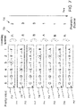
- FIG. 6 depicts priority ordered query execution plans 611-617 stored in a plan cache 610 when the incoming queries 620 have a relatively low query locality (compared to the example depicted in FIG. 7 ).
- the plan cache 610 can store six query execution plans. Initially, the plan cache 610 includes the query execution plans for the following queries: A, B, C, D, E, and F, respectively. These query execution plans can be ordered based on their priority. In the depicted example, a smaller priority value indicates a higher priority and a larger priority value indicates a lower priority.
- the initial priority order list 611 of the query execution plans stored in the plan cache 610 can be represented as: C ⁇ D ⁇ B ⁇ A ⁇ E ⁇ F, i.e., the query execution plan for query C has the lowest priority (with priority value 6) and the query execution plan for query F has the highest priority (with priority value 1).
- priority orders can be tracked by a plan priority tracker (e.g., 264), and the physical order of the query execution plans stored in the plan cache 610 can be different from their priority order.
- an LRU plan eviction policy is implemented for the plan cache 610, which removes the least recently used query execution plan from the plan cache 610 upon a cache miss.
- a promotion method can be implemented such that a cache hit can cause the corresponding query execution plan to move to the highest priority order.
- the incoming queries 620 includes the following query sequence: "DABCDB.”
- the first query D causes a cache hit, as indicated by the circled D in the plan cache 610.
- the query execution plan corresponding to query D is promoted to the highest priority order, and the query execution plans in the plan cache 610 is updated to a new priority order list 612: C ⁇ B ⁇ A ⁇ E ⁇ F ⁇ D.
- the second query A causes a cache hit (as indicated by the circled A in the plan cache), and its corresponding query execution plan is promoted to the highest priority order, resulting in an updated priority order list 613: C ⁇ B ⁇ E ⁇ F ⁇ D ⁇ A.
- the final priority order list 617 becomes E ⁇ F ⁇ A ⁇ C ⁇ D ⁇ B.
- query locality can be measured by accumulating promotion distances 630 for the plurality of incoming queries 620.
- a promotion distance for the incoming query can be calculated as an absolute difference between the new and old priority orders of the query execution plan corresponding to the incoming query. For example, when the first query D causes the cache hit, the priority order of the corresponding query execution plan changes from 5 to 1. Thus, the promotion distance for the first query D is 4. Likewise, when the second query A causes the cache hit, the priority order of the corresponding query execution plan changes from 4 to 1. Thus, the promotion distance for the second query A is 3.
- the promotion distances for the six incoming queries "DABCDB” are calculated to be 4, 3, 4, 5, 3, and 2, respectively.
- a promotion distance for the incoming query can be set to a count of query execution plans stored in the plan cache. For example, if an incoming query is Z which causes a cache miss because it has no corresponding query execution plan stored in the plan cache 610, the promotion distance for the incoming query Z can be set to 6, which is the total number of query execution plans stored in the plan cache 610.
- FIG. 7 depicts priority ordered query plans 711-717 stored in a plan cache 710 when the incoming queries 720 have a relatively high query locality (compared to the example depicted in FIG. 6 ).
- the plan cache 710 also stores six query execution plans respectively for queries A, B, C, D, E, and F, and their initial priority order list 711 is identical to 611, i.e., C ⁇ D ⁇ B ⁇ A ⁇ E ⁇ F.
- the incoming queries 720 "ABBABA" has more repetitive queries and less variation than 620.
- each of the incoming query results in a cache hit.
- the priority order list 711 can be progressively updated to 712, 713, and so on, until 717.
- the calculated promotion distances for the incoming queries "ABBABA” are 2, 3, 0, 1, 1, and 1, respectively.
- an increase of accumulated promotion distances indicates a decrease in query locality and a decrease of accumulated promotion distances indicates an increase in query locality.
- a large promotion distance occurs when a query execution plan with a low priority is promoted (in case of a cache hit) or no corresponding query execution plan exists in the plan cache (i.e., in case of a cache miss). Thus, it indicates the likelihood of reusing the same set of query execution plans from the plan cache is low.
- a small promotion distance suggests the promoted query execution plan already has a high priority before such promotion (in case of a cache hit). Thus, it indicates the likelihood of reusing the same set of query execution plans from the plan cache is high.
- the larger the accumulated promotion distance the lower the query locality, and vice versa.
- the query locality can be simply defined as the reciprocal of the accumulated promotion distance.
- the measured query locality is 1/21 for the incoming queries depicted in FIG. 6 and 1 / 8 for the incoming queries depicted in FIG. 7 .
- query locality can be defined as the negative of the accumulated promotion distance.
- the measured query locality is -21 for the incoming queries depicted in FIG. 6 and -8 for the incoming queries depicted in FIG. 7 .
- Other definitions are also possible so long as the query locality is inversely proportional (either linearly or nonlinearly) to the accumulated promotion distance.
- Example 7 Example Alternative Methods for Measuring Query Locality
- the corresponding query execution plan after a cache hit may not move to the highest priority order.
- the found query execution plan may be promoted to the second (or third, fourth, etc.) highest priority order in the plan cache.
- the found query execution plan may be promoted to a priority order that is higher than the previous priority order by a predefined level (e.g., 1, 2, 3, or more levels higher).
- a predefined level e.g. 1, 2, 3, or more levels higher.
- the implemented plan eviction policy does not need to be LRU.
- the methods described herein can be applied to any plan eviction policy so long as a cache hit can promote the corresponding query execution plan to a higher priority order, unless the corresponding query execution plan already has the highest priority order (in which case its priority order will remain unchanged).
- query locality is based on a particular method of accumulating promotion distances for the incoming queries, it is to be understood that query locality can be measured by other methods.
- the parameters ⁇ and/or ⁇ can be predefined to adjust the "degree of penalty" (in terms of the measured promotion distance) when cache miss occurs.
- the query locality can be measured based on the calculation of reuse distances (instead of promotion distances) for the incoming queries, where the reuse distance for a query X can be defined as the number of distinct queries between processing this query X and a prior processing of the same query X.
- the query locality in a time window can be simply measured by the hit ratio, which can be calculated by dividing the number of cache hits by the total number of incoming queries in the time window. Higher hit ratio (or conversely, lower miss ratio) can indicate higher query locality, and vice versa. In such circumstances, the query locality simply measures the frequency of reusing query execution plans in the plan cache when processing the incoming queries, regardless of the priority orders of the query execution plans.
- the query locality in a time window can be simply measured based on counting the unique number of queries occurred in the time window. The more unique number of queries in the time window indicates more query variations, thus the lower query locality, and vice versa. Similarly, the priority order of the query execution plans needs not to be considered if the query locality is measured based on the unique number of queries occurred in a time window. Other statistical metrics that measure query variation in a time window can similarly be used to quantify the query locality, where lower query variation in the time window indicates higher query locality.
- Example 8 Example Methods for Determining Amount of Increment or Decrement of Query Plan Cache Size
- plan cache size can be increased by allocating an extra cache or memory space to the plan cache (e.g., allocating an extra cache space in the cache pool 190 to the plan cache 192), or decreased by removing a portion of the plan cache (e.g., releasing a portion of the plan cache 192 to the cache pool 190).
- the increase and/or decrease of the plan cache size can be constrained within predefined maximum and/or minimum plan cache size limits.
- the maximum and/or minimum plan cache size limits can be fixed values.
- the maximum and/or minimum plan cache size limits can be configured to be adaptive to the size of a cache pool (e.g., 190).
- the increase of the plan cache size can be limited by a maximum cache size that has a fixed value (e.g., 1 GB, 2 GB, 10 GB, etc.), or a predefined percentage (e.g., 50%, 60%, 75%, etc.) of the size of the cache pool.
- the decrease of the plan cache size can be limited by a minimum cache size that has a fixed value (e.g., 10 MB, 100 MB, 200 MB, etc.), or a predefined percentage (e.g., 10%, 20%, 25%, etc.) of the size of the cache pool.
- a fixed value e.g. 10 MB, 100 MB, 200 MB, etc.
- a predefined percentage e.g. 10%, 20%, 25%, etc.
- the amount of increase or decrease of the plan cache size can be fixed.
- an extra cache of a predefined size e.g., 1 MB, 10 MB, 25 MB, etc.
- a cache portion having a predefined size e.g., 1 MB, 10 MB, 25 MB, etc.
- the amount of increase or decrease of the plan cache size can be adaptive or proportional to the current plan cache size (i.e., the size the plan cache before such increase or decrease). For example, to increase the plan cache size, an extra cache whose size is a predefined percentage (e.g., 0.5%, 1%, 2%, etc.) of the current plan cache size can be added to the plan cache. Likewise, to decrease the plan cache size, a cache portion whose size is a predefined percentage (e.g., 0.5%, 1%, 2%, etc.) of the current plan cache size can be removed from the plan cache.
- a predefined percentage e.g. 0.5%, 1%, 2%, etc.
- the amount of increase or decrease of the plan cache size can be adaptive or proportional to a size of a query execution plan stored in the plan cache (also referred to as a "reference query plan").
- a size of a query execution plan stored in the plan cache also referred to as a "reference query plan”
- an extra cache can be added to the plan cache, wherein the size of the extra cache can be proportional to (e.g., 50%, 100%, 200%, etc.) the size of the reference query plan.
- a cache portion can be removed from the plan cache, wherein the size of the cache portion can be proportional to (e.g., 50%, 100%, 150%, etc.) the size of the reference query plan.
- the query execution plan which has been last stored in the plan cache can be selected as the reference execution plan.
- the reference query plan can be selected based on other criteria. For example, the reference query plan can be selected to be the oldest query execution plan, the largest query execution plan, the query execution plan associated with the most compilation time, the query execution plan associated with the lowest priority order, or the query execution plan associated with the highest (or lowest) hit ratio, and so on.
- the amount of increase or decrease of the plan cache size can be adaptive or proportional to a change of measured query locality. For example, to increase the plan cache size, an extra cache can be added to the plan cache, wherein the size of the extra cache can proportional to the decrease of measured query locality (e.g., a larger increase of accumulated promotional distance can lead to a larger increase of the plan cache). Likewise, to decrease the plan cache size, a cache portion can be removed from the plan cache, wherein the size of the cache portion can be proportional to the increase of measured query locality (e.g., a larger decrease of accumulated promotional distance can lead to a larger decrease of the plan cache).
- a trend of the measured query locality over time can be measured.
- the trend can be measured by slopes of the measured query locality over time.
- the amount of increase or decrease of the plan cache size can be adaptive or proportional to the trend (or slope) of the measured query locality. For example, an increasing trend (e.g., progressively increasing positive slope) of the measured query locality can lead to a larger decrease of the plan cache, whereas a decreasing trend (e.g., progressively decreasing negative slope) of the measured query locality can lead to a larger increase of the plan cache.
- Example 9 Example Uses Cases Illustrating Dynamic Adjustment of Query Plan Cache Size
- Example use cases are described below, in reference to FIGS. 8-9 , to further illustrate the method of intelligent query plan cache size management described above. It is to be understood that FIGS. 8-9 are merely for illustrative purposes and are not necessarily drawn to scale. For example, the shape of certain curves described below can vary from what are depicted in the figures.
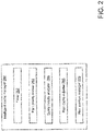
- FIG. 8 schematically shows an example plot 800, depicting total compilation time accumulated for some incoming queries according to three different cache plan management methods, as described below.
- the displayed x-axis is the run time when incoming queries are submitted. Alternatively, the x-axis can refer to the number of incoming queries.
- the y-axis is the total compilation time (i.e., accumulated compilation time) of incoming queries.
- the curve 810 shows the total compilation time accumulated for the incoming queries when a specific query eviction policy (e.g., LRU) is implemented while the plan cache has a fixed predetermined size (also referred to as the "fixed plan cache").
- the curve 820 shows the total compilation time accumulated for the incoming queries when the same query eviction policy is implemented while the size of the plan cache can be dynamically adjusted using the method described above (also referred to as the "dynamic plan cache"). For example, the plan cache size can be increased when the measured query locality decrease and decreased when the measured query locality increase.
- the curve 830 shows the total compilation time accumulated for the incoming queries in an ideal situation where the plan cache is assumed to have an unlimited size such that no query execution plan is evicted from the plan cache (also referred to as the "ideal plan cache").
- the total compilation time depicted in the fixed plan cache 810 and dynamic plan cache 820 will depend on the implemented plan eviction policy. For example, the total compilation time in 810 or 820 will increase if there is a cache miss, which can occur in the case of new query which has to be compiled for the first time, or if an old query has no corresponding query execution plan stored in the plan cache (i.e., the previously compiled query execution plan was evicted from the plan cache according to the implemented plan eviction policy). On other hand, the total compilation time in 810 or 820 will remain flat if there is a cache hit, that is, when an old query has a corresponding query execution plan stored in the plan cache so that the query does not need to be recompiled.
- the total compilation time depicted for the ideal plan cache 830 can be estimated by assuming that no query execution plan is evicted from the query execution plan cache. Estimation of total compilation times for the ideal situation can be implemented by measuring time saved from not compiling old queries. For example, if an incoming query is new, this new query must be compiled for the first time, even if the size of the query execution plan cache is unlimited. Thus, the ideal compilation time will increase by the amount of time to compile this new query. But if the incoming query is old, its previously compiled query execution plan must exist in the query execution plan cache because, in the ideal situation, it has an unlimited size and never evicts any query execution plan.
- the ideal compilation time establishes a floor or minimum compilation time that is possible to compile the incoming queries. Any measured actual compilation time (e.g., 810 and 820) will be either the same as the ideal compilation time (when no eviction of query execution plan occurs) or larger than the ideal compilation time (when eviction of query execution plan occurs).
- the curves 810, 820, and 830 have certain overlap at the very beginning when most incoming queries are new (thus, they must be compiled for the first time). Then the three curves 810, 820, and 830 start to diverge. Specifically, while the total compilation time of all three curves 810, 820, and 830 progressively increase over time, the curve 830 always remains at the lowest (i.e., establishing the floor, as described above), while the curve 820 is positioned between 810 and 830. In other words, the total compilation time for the fixed plan cache 810 increases at a faster pace than the total compilation time for the dynamic plan cache 820. Thus, by dynamically adjusting the plan cache size, the total compilation time can be reduced even though both methods implement the same plan eviction policy.
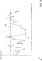
- FIG. 9 shows a plot 900 including two curves depicting the size of plan cache over time.
- the dashed curve 910 represents the constant plan cache size corresponding to the fixed plan cache curve 810, that is, when a specific query eviction policy is implemented while the plan cache size is fixed.
- the solid curve 920 shows the variation of plan cache size corresponding to the dynamic plan cache curve 820, that is, when the same query eviction policy is implemented while the size of the plan cache can be dynamically adjusted based on the measured query locality.
- the curve 920 can increase above the curve 910, indicating that the plan cache of 920 may need to be increased to a larger size than the fixed plan cache of 910. This can occur when the certain incoming queries have very low query locality.
- increasing the size of the plan cache (even above the fixed plan cache of 910) in this situation can accommodate or store more query execution plans so that the likelihood of cache hit for the following queries can increase. This is evidenced by the immediate drop of the plan cache size (which can be far below the fixed plan cache of 910).
- the average plan cache size over time for the curve 920 can be lower than 910, indicating that overall the plan cache size that is needed to store the query execution plans can be reduced, while simultaneously reducing total compilation time (as shown in FIG. 8 ).
- the measured query locality may increase, leading to a reduction of the plan cache size (e.g., to release cache resource to the cache pool) without negatively affecting the performance of query execution because few query execution plans are evicted from the plan cache.
- the plan cache is significantly reduced such that some incoming queries have to be recompiled because their previously compiled query execution plans were evicted from the plan cache, the measured query locality may decrease, leading to an increase of the plan cache size so as to reduce or mitigate the negative effect of plan eviction policy.
- the intelligent cache manager can dynamically adjust the cache plan size based on actual need of the plan cache, i.e., increasing or reducing the plan cache size as the need of plan cache increases or decreases, respectively. This is important because the need of plan cache may be unpredictable in the run time and can vary significantly depending on what queries are submitted by clients. As a result, the disclosed technology can continuously find the appropriate (or optimize) the plan cache size in order to maximize the performance of the database management system.
- the appropriate (or optimized) plan cache size can struck a right balance between query performance and resource management: on one hand, it is not too small to cause frequent evictions of query plans and recompilation of old queries; on the other hand, it is not too big to waste valuable cache memory resources.
- the intelligent plan cache management technology described herein can be easily deployed to any database management system implementing any query plan eviction policy.
- the disclosed method of dynamic adjustment of cache plan size can be performed automatically by the intelligent cache manager without human interaction. Further, such dynamic adjustment of cache plan size can be achieved on the fly or in real-time (e.g., adjustment of the cache plan size can be realized within a fraction of a second after evaluating the query locality in a time window).
- FIG. 10 depicts an example of a suitable computing system 1000 in which the described innovations can be implemented.
- the computing system 1000 is not intended to suggest any limitation as to scope of use or functionality of the present disclosure, as the innovations can be implemented in diverse computing systems.
- the computing system 1000 includes one or more processing units 1010, 1015 and memory 1020, 1025.
- the processing units 1010, 1015 execute computer-executable instructions, such as for implementing the features described in the examples herein.
- a processing unit can be a general-purpose central processing unit (CPU), processor in an application-specific integrated circuit (ASIC), or any other type of processor.
- a processing unit can be a general-purpose central processing unit (CPU), processor in an application-specific integrated circuit (ASIC), or any other type of processor.
- ASIC application-specific integrated circuit
- FIG. 10 shows a central processing unit 1010 as well as a graphics processing unit or co-processing unit 1015.
- the tangible memory 1020, 1025 can be volatile memory (e.g., registers, cache, RAM), non-volatile memory (e.g., ROM, EEPROM, flash memory, etc.), or some combination of the two, accessible by the processing unit(s) 1010, 1015.
- the memory 1020, 1025 stores software 1080 implementing one or more innovations described herein, in the form of computer-executable instructions suitable for execution by the processing unit(s) 1010, 1015.
- a computing system 1000 can have additional features.
- the computing system 1000 includes storage 1040, one or more input devices 1050, one or more output devices 1060, and one or more communication connections 1070, including input devices, output devices, and communication connections for interacting with a user.
- An interconnection mechanism such as a bus, controller, or network interconnects the components of the computing system 1000.
- operating system software provides an operating environment for other software executing in the computing system 1000, and coordinates activities of the components of the computing system 1000.
- the tangible storage 1040 can be removable or non-removable, and includes magnetic disks, magnetic tapes or cassettes, CD-ROMs, DVDs, or any other medium which can be used to store information in a non-transitory way and which can be accessed within the computing system 1000.
- the storage 1040 stores instructions for the software implementing one or more innovations described herein.
- the input device(s) 1050 can be an input device such as a keyboard, mouse, pen, or trackball, a voice input device, a scanning device, touch device (e.g., touchpad, display, or the like) or another device that provides input to the computing system 1000.
- the output device(s) 1060 can be a display, printer, speaker, CD-writer, or another device that provides output from the computing system 1000.
- the communication connection(s) 1070 enable communication over a communication medium to another computing entity.
- the communication medium conveys information such as computer-executable instructions, audio or video input or output, or other data in a modulated data signal.
- a modulated data signal is a signal that has one or more of its characteristics set or changed in such a manner as to encode information in the signal.
- communication media can use an electrical, optical, RF, or other carrier.
- program modules or components include routines, programs, libraries, objects, classes, components, data structures, etc. that perform particular tasks or implement particular abstract data types.
- the functionality of the program modules can be combined or split between program modules as desired in various embodiments.
- Computer-executable instructions for program modules can be executed within a local or distributed computing system.
- Any of the computer-readable media herein can be non-transitory (e.g., volatile memory such as DRAM or SRAM, nonvolatile memory such as magnetic storage, optical storage, or the like) and/or tangible. Any of the storing actions described herein can be implemented by storing in one or more computer-readable media (e.g., computer-readable storage media or other tangible media). Any of the things (e.g., data created and used during implementation) described as stored can be stored in one or more computer-readable media (e.g., computer-readable storage media or other tangible media). Computer-readable media can be limited to implementations not consisting of a signal.
- Any of the methods described herein can be implemented by computer-executable instructions in (e.g., stored on, encoded on, or the like) one or more computer-readable media (e.g., computer-readable storage media or other tangible media) or one or more computer-readable storage devices (e.g., memory, magnetic storage, optical storage, or the like). Such instructions can cause a computing device to perform the method.
- computer-executable instructions e.g., stored on, encoded on, or the like
- computer-readable media e.g., computer-readable storage media or other tangible media
- computer-readable storage devices e.g., memory, magnetic storage, optical storage, or the like.
- Such instructions can cause a computing device to perform the method.
- the technologies described herein can be implemented in a variety of programming languages.
- Example 13 Example Cloud Computing Environment
- FIG. 11 depicts an example cloud computing environment 1100 in which the described technologies can be implemented, including, e.g., the system disclosed above and other systems herein.
- the cloud computing environment 1100 comprises cloud computing services 1110.
- the cloud computing services 1110 can comprise various types of cloud computing resources, such as computer servers, data storage repositories, networking resources, etc.
- the cloud computing services 1110 can be centrally located (e.g., provided by a data center of a business or organization) or distributed (e.g., provided by various computing resources located at different locations, such as different data centers and/or located in different cities or countries).
- the cloud computing services 1110 are utilized by various types of computing devices (e.g., client computing devices), such as computing devices 1120, 1122, and 1123.
- the computing devices e.g., 1120, 1122, and 1124
- the computing devices e.g., 1120, 1122, and 1124
- cloud-based, on-premises-based, or hybrid scenarios can be supported.
- a computer-implemented method comprising: measuring query locality during execution of a plurality of incoming queries in a database management system, wherein the database management system comprises a query execution plan cache which has a size that can store at least some of query execution plans generated for the plurality of incoming queries; and based on the measured query locality, adjusting the size of the query execution plan cache.
- Clause 3 The method of clause 2, wherein if an incoming query has a generated query execution plan stored in the query execution plan cache, a promotion distance for the incoming query is determined based on a priority order of the generated query execution plan in the query execution plan cache.
- Clause 4 The method of any one of clauses 2-3, wherein if an incoming query has no generated query execution plan stored in the query execution plan cache, a promotion distance for the incoming query is set to a count of query execution plans stored in the query execution plan cache.
- Clause 6 The method of clause 5, wherein increasing the size of the query execution plan cache comprises allocating an extra cache to the query execution plan cache, wherein a size of the extra cache is a predefined fraction of a difference between a predefined maximum cache size and the size of the query execution plan cache before allocating the extra cache.
- Clause 7 The method of any one of clauses 5-6, wherein the time window has a predefined duration or has a duration when a predetermined number of incoming queries are submitted for execution.
- adjusting the size of the query execution plan cache comprises decreasing the size of the query execution plan cache if the measured query locality has increased over a time window.
- Clause 9 The method of clause 8, wherein decreasing the size of the query execution plan cache comprises removing a cache portion out of the query execution plan cache, wherein the cache portion has a predefined size.
- Clause 10 The method of any one of clauses 8-9, wherein the time window has a predefined duration or has a duration when a predetermined number of incoming queries are submitted for execution.
- a computing system comprising: memory; one or more hardware processors coupled to the memory; and one or more computer readable storage media storing instructions that, when loaded into the memory, cause the one or more hardware processors to perform operations comprising: measuring query locality during execution of a plurality of incoming queries in a database management system, wherein the database management system comprises a query execution plan cache which has a size that can store at least some of query execution plans generated for the plurality of incoming queries; and based on the measured query locality, adjusting the size of the query execution plan cache.
- measuring query locality comprises accumulating promotion distances for the plurality of incoming queries, wherein an increase of accumulated promotion distances indicates a decrease in query locality and a decrease of accumulated promotion distances indicates an increase in query locality.
- Clause 13 The system of clause 12, wherein if an incoming query has a generated query execution plan stored in the query execution plan cache, a promotion distance for the incoming query is determined based on a priority order of the generated query execution plan in the query execution plan cache, wherein if the incoming query has no generated query execution plan stored in the query execution plan cache, the promotion distance for the incoming query is set to a count of query execution plans stored in the query execution plan cache.
- adjusting the size of the query execution plan cache comprises increasing the size of the query execution plan cache if the measured query locality has decreased over a time window, and decreasing the size of the query execution plan cache if the measured query locality has increased over the time window.
- Clause 16 The system of any one of clauses 14-15, wherein increasing the size of the query execution plan cache comprises allocating an extra cache to the query execution plan cache, and decreasing the size of the query execution plan cache comprises removing a cache portion from the query execution plan cache.
- Clause 17 The system of clause 16, wherein the extra cache allocated to the query execution plan cache and/or the cache portion removed from the query execution plan cache have respective sizes that are predefined or adaptive to the size of the query execution plan cache.
- Clause 18 The system of clause 16, wherein the extra cache allocated to the query execution plan cache and/or the cache portion removed from the query execution plan cache have respective sizes that are adaptive to a change of measured query locality over the time window.
- adjusting the size of the query execution plan cache comprises increasing the size of the query execution plan cache if the measured query locality has decreased over a first threshold over a time window, and decreasing the size of the query execution plan cache if the measured query locality has increased over a second threshold over the time window.
- One or more computer-readable media having encoded thereon computer-executable instructions causing one or more processors to perform a method comprising: measuring query locality during execution of a plurality of incoming queries in a database management system, wherein the database management system comprises a query execution plan cache which has a size that can store at least some of query execution plans generated for the plurality of incoming queries; and based on the measured query locality, adjusting the size of the query execution plan cache; wherein measuring query locality comprises accumulating promotion distances for the plurality of incoming queries, wherein an increase of accumulated promotion distances indicates a decrease in query locality and a decrease of accumulated promotion distances indicates an increase in query locality; wherein adjusting the size of the query execution plan cache comprises increasing the size of the query execution plan cache if the measured query locality has decreased over a time window, and decreasing the size of the query execution plan cache if the measured query locality has increased over the time window.
Landscapes
- Engineering & Computer Science (AREA)
- Theoretical Computer Science (AREA)
- Databases & Information Systems (AREA)
- General Engineering & Computer Science (AREA)
- General Physics & Mathematics (AREA)
- Physics & Mathematics (AREA)
- Data Mining & Analysis (AREA)
- Computational Linguistics (AREA)
- Operations Research (AREA)
- Information Retrieval, Db Structures And Fs Structures Therefor (AREA)
- Memory System Of A Hierarchy Structure (AREA)
- Computer Hardware Design (AREA)
- Quality & Reliability (AREA)
Priority Applications (1)
| Application Number | Priority Date | Filing Date | Title |
|---|---|---|---|
| EP25219267.9A EP4682738A3 (de) | 2021-07-20 | 2022-06-01 | Intelligente verwaltung der cache-grösse von abfrageplänen |
Applications Claiming Priority (1)
| Application Number | Priority Date | Filing Date | Title |
|---|---|---|---|
| US17/381,062 US11567938B1 (en) | 2021-07-20 | 2021-07-20 | Intelligent query plan cache size management |
Related Child Applications (1)
| Application Number | Title | Priority Date | Filing Date |
|---|---|---|---|
| EP25219267.9A Division EP4682738A3 (de) | 2021-07-20 | 2022-06-01 | Intelligente verwaltung der cache-grösse von abfrageplänen |
Publications (3)
| Publication Number | Publication Date |
|---|---|
| EP4123473A1 true EP4123473A1 (de) | 2023-01-25 |
| EP4123473B1 EP4123473B1 (de) | 2025-12-03 |
| EP4123473C0 EP4123473C0 (de) | 2025-12-03 |
Family
ID=81878203
Family Applications (2)
| Application Number | Title | Priority Date | Filing Date |
|---|---|---|---|
| EP22176751.0A Active EP4123473B1 (de) | 2021-07-20 | 2022-06-01 | Intelligente abfrageplan-cache-grössenverwaltung |
| EP25219267.9A Pending EP4682738A3 (de) | 2021-07-20 | 2022-06-01 | Intelligente verwaltung der cache-grösse von abfrageplänen |
Family Applications After (1)
| Application Number | Title | Priority Date | Filing Date |
|---|---|---|---|
| EP25219267.9A Pending EP4682738A3 (de) | 2021-07-20 | 2022-06-01 | Intelligente verwaltung der cache-grösse von abfrageplänen |
Country Status (3)
| Country | Link |
|---|---|
| US (1) | US11567938B1 (de) |
| EP (2) | EP4123473B1 (de) |
| CN (1) | CN115640313A (de) |
Families Citing this family (3)
| Publication number | Priority date | Publication date | Assignee | Title |
|---|---|---|---|---|
| US12137081B2 (en) * | 2021-09-09 | 2024-11-05 | Texas Instruments Incorporated | Resource access in a microcontroller |
| US11907218B1 (en) * | 2022-08-12 | 2024-02-20 | Oracle International Corporation | Automatic prevention of plan regressions |
| US12135715B1 (en) | 2023-04-28 | 2024-11-05 | Snowflake Inc. | Multi-phase query plan caching |
Citations (2)
| Publication number | Priority date | Publication date | Assignee | Title |
|---|---|---|---|---|
| US20170337138A1 (en) * | 2016-05-18 | 2017-11-23 | International Business Machines Corporation | Dynamic cache management for in-memory data analytic platforms |
| US20210073232A1 (en) * | 2019-09-11 | 2021-03-11 | Sap Se | Database management system query plan cache management |
Family Cites Families (9)
| Publication number | Priority date | Publication date | Assignee | Title |
|---|---|---|---|---|
| JP4162184B2 (ja) * | 2001-11-14 | 2008-10-08 | 株式会社日立製作所 | データベース管理システムの実行情報を取得する手段を有する記憶装置 |
| US7676453B2 (en) * | 2004-04-22 | 2010-03-09 | Oracle International Corporation | Partial query caching |
| US7502775B2 (en) | 2006-03-31 | 2009-03-10 | International Business Machines Corporation | Providing cost model data for tuning of query cache memory in databases |
| US8600977B2 (en) * | 2007-10-17 | 2013-12-03 | Oracle International Corporation | Automatic recognition and capture of SQL execution plans |
| US7937385B2 (en) * | 2008-05-05 | 2011-05-03 | International Business Machines Corporation | Obtaining a plan for executing a query in a relational database |
| US8775413B2 (en) * | 2008-06-30 | 2014-07-08 | Teradata Us, Inc. | Parallel, in-line, query capture database for real-time logging, monitoring and optimizer feedback |
| US9436732B2 (en) * | 2013-03-13 | 2016-09-06 | Futurewei Technologies, Inc. | System and method for adaptive vector size selection for vectorized query execution |
| US11093496B1 (en) * | 2017-11-22 | 2021-08-17 | Amazon Technologies, Inc. | Performance-based query plan caching |
| US11341133B2 (en) * | 2018-10-26 | 2022-05-24 | International Business Machines Corporation | Method and system for collaborative and dynamic query optimization in a DBMS network |
-
2021
- 2021-07-20 US US17/381,062 patent/US11567938B1/en active Active
-
2022
- 2022-06-01 EP EP22176751.0A patent/EP4123473B1/de active Active
- 2022-06-01 EP EP25219267.9A patent/EP4682738A3/de active Pending
- 2022-06-02 CN CN202210625467.XA patent/CN115640313A/zh active Pending
Patent Citations (2)
| Publication number | Priority date | Publication date | Assignee | Title |
|---|---|---|---|---|
| US20170337138A1 (en) * | 2016-05-18 | 2017-11-23 | International Business Machines Corporation | Dynamic cache management for in-memory data analytic platforms |
| US20210073232A1 (en) * | 2019-09-11 | 2021-03-11 | Sap Se | Database management system query plan cache management |
Non-Patent Citations (1)
| Title |
|---|
| HIROAKI KOBAYASHI ET AL: "Locality analysis to control dynamically way-adaptable caches", MEMORY PERFORMANCE, ACM, 2 PENN PLAZA, SUITE 701 NEW YORK NY 10121-0701 USA, 29 September 2004 (2004-09-29), pages 25 - 32, XP058328248, DOI: 10.1145/1152922.1101874 * |
Also Published As
| Publication number | Publication date |
|---|---|
| EP4682738A3 (de) | 2026-04-01 |
| US20230024210A1 (en) | 2023-01-26 |
| US11567938B1 (en) | 2023-01-31 |
| EP4123473B1 (de) | 2025-12-03 |
| EP4123473C0 (de) | 2025-12-03 |
| CN115640313A (zh) | 2023-01-24 |
| EP4682738A2 (de) | 2026-01-21 |
Similar Documents
| Publication | Publication Date | Title |
|---|---|---|
| EP4123473A1 (de) | Intelligente abfrageplan-cache-grössenverwaltung | |
| US12530352B2 (en) | Intelligent query plan cache size management | |
| US10311025B2 (en) | Duplicate in-memory shared-intermediate data detection and reuse module in spark framework | |
| US8402223B2 (en) | Cache eviction using memory entry value | |
| US9189410B2 (en) | Hypervisor-based flash cache space management in a multi-VM environment | |
| US20140173199A1 (en) | Enhancing Analytics Performance Using Distributed Multi-Tiering | |
| US8601213B2 (en) | System, method, and computer-readable medium for spool cache management | |
| US20200310985A1 (en) | Lease cache memory devices and methods | |
| US20090320022A1 (en) | File System Object Node Management | |
| US10606795B2 (en) | Methods for managing a buffer cache and devices thereof | |
| US20250390435A1 (en) | Method and apparatus for evicting cached data, electronic device, and storage medium | |
| CN114528068A (zh) | 一种消除无服务器计算容器冷启动的方法 | |
| CN104166596A (zh) | 一种内存分配方法及节点 | |
| KR101334189B1 (ko) | 멀티 프로세서 시스템 온 칩에서의 메모리 관리 방법 | |
| US8621156B1 (en) | Labeled cache system | |
| Cheng et al. | Take Out the {TraChe}: Maximizing (Tra) nsactional Ca (che) Hit Rate | |
| CN120578668B (zh) | 图计算方法、装置、电子设备及存储介质 | |
| Naeem et al. | Skewed distributions in semi-stream joins: How much can caching help? | |
| US7171519B2 (en) | System, method and program for assessing the activity level of a database management system | |
| CN120407902B (zh) | 面向浏览器环境的向量检索系统 | |
| US12393582B2 (en) | Automatic recompilation for parameterized queries | |
| US20180025094A1 (en) | Increasing performance of in-memory databases using re-ordered query execution plans | |
| CN120872860A (zh) | 一种基于程序动态特征的预取优化方法、系统及存储介质 | |
| CN118916145A (zh) | 调度方法和装置 | |
| Gupta et al. | Cache access pattern based algorithm for performance improvement of cache memory management |
Legal Events
| Date | Code | Title | Description |
|---|---|---|---|
| PUAI | Public reference made under article 153(3) epc to a published international application that has entered the european phase |
Free format text: ORIGINAL CODE: 0009012 |
|
| STAA | Information on the status of an ep patent application or granted ep patent |
Free format text: STATUS: THE APPLICATION HAS BEEN PUBLISHED |
|
| AK | Designated contracting states |
Kind code of ref document: A1 Designated state(s): AL AT BE BG CH CY CZ DE DK EE ES FI FR GB GR HR HU IE IS IT LI LT LU LV MC MK MT NL NO PL PT RO RS SE SI SK SM TR |
|
| TPAC | Observations filed by third parties |
Free format text: ORIGINAL CODE: EPIDOSNTIPA |
|
| STAA | Information on the status of an ep patent application or granted ep patent |
Free format text: STATUS: REQUEST FOR EXAMINATION WAS MADE |
|
| 17P | Request for examination filed |
Effective date: 20230706 |
|
| RBV | Designated contracting states (corrected) |
Designated state(s): AL AT BE BG CH CY CZ DE DK EE ES FI FR GB GR HR HU IE IS IT LI LT LU LV MC MK MT NL NO PL PT RO RS SE SI SK SM TR |
|
| STAA | Information on the status of an ep patent application or granted ep patent |
Free format text: STATUS: EXAMINATION IS IN PROGRESS |
|
| 17Q | First examination report despatched |
Effective date: 20250528 |
|
| GRAP | Despatch of communication of intention to grant a patent |
Free format text: ORIGINAL CODE: EPIDOSNIGR1 |
|
| STAA | Information on the status of an ep patent application or granted ep patent |
Free format text: STATUS: GRANT OF PATENT IS INTENDED |
|
| INTG | Intention to grant announced |
Effective date: 20250729 |
|
| GRAS | Grant fee paid |
Free format text: ORIGINAL CODE: EPIDOSNIGR3 |
|
| GRAA | (expected) grant |
Free format text: ORIGINAL CODE: 0009210 |
|
| STAA | Information on the status of an ep patent application or granted ep patent |
Free format text: STATUS: THE PATENT HAS BEEN GRANTED |
|
| AK | Designated contracting states |
Kind code of ref document: B1 Designated state(s): AL AT BE BG CH CY CZ DE DK EE ES FI FR GB GR HR HU IE IS IT LI LT LU LV MC MK MT NL NO PL PT RO RS SE SI SK SM TR |
|
| REG | Reference to a national code |
Ref country code: CH Ref legal event code: F10 Free format text: ST27 STATUS EVENT CODE: U-0-0-F10-F00 (AS PROVIDED BY THE NATIONAL OFFICE) Effective date: 20251203 Ref country code: GB Ref legal event code: FG4D |
|
| REG | Reference to a national code |
Ref country code: DE Ref legal event code: R096 Ref document number: 602022025977 Country of ref document: DE |
|
| REG | Reference to a national code |
Ref country code: IE Ref legal event code: FG4D |
|
| U01 | Request for unitary effect filed |
Effective date: 20251217 |
|
| U07 | Unitary effect registered |
Designated state(s): AT BE BG DE DK EE FI FR IT LT LU LV MT NL PT RO SE SI Effective date: 20251223 |
|
| PG25 | Lapsed in a contracting state [announced via postgrant information from national office to epo] |
Ref country code: ES Free format text: LAPSE BECAUSE OF FAILURE TO SUBMIT A TRANSLATION OF THE DESCRIPTION OR TO PAY THE FEE WITHIN THE PRESCRIBED TIME-LIMIT Effective date: 20251203 |
|
| PG25 | Lapsed in a contracting state [announced via postgrant information from national office to epo] |
Ref country code: NO Free format text: LAPSE BECAUSE OF FAILURE TO SUBMIT A TRANSLATION OF THE DESCRIPTION OR TO PAY THE FEE WITHIN THE PRESCRIBED TIME-LIMIT Effective date: 20260303 |
|
| PG25 | Lapsed in a contracting state [announced via postgrant information from national office to epo] |
Ref country code: HR Free format text: LAPSE BECAUSE OF FAILURE TO SUBMIT A TRANSLATION OF THE DESCRIPTION OR TO PAY THE FEE WITHIN THE PRESCRIBED TIME-LIMIT Effective date: 20251203 |
|
| PG25 | Lapsed in a contracting state [announced via postgrant information from national office to epo] |
Ref country code: RS Free format text: LAPSE BECAUSE OF FAILURE TO SUBMIT A TRANSLATION OF THE DESCRIPTION OR TO PAY THE FEE WITHIN THE PRESCRIBED TIME-LIMIT Effective date: 20260303 |