EP4123336A1 - Apparatus and method for monitoring surrounding environment of vehicle - Google Patents
Apparatus and method for monitoring surrounding environment of vehicle Download PDFInfo
- Publication number
- EP4123336A1 EP4123336A1 EP22184734.6A EP22184734A EP4123336A1 EP 4123336 A1 EP4123336 A1 EP 4123336A1 EP 22184734 A EP22184734 A EP 22184734A EP 4123336 A1 EP4123336 A1 EP 4123336A1
- Authority
- EP
- European Patent Office
- Prior art keywords
- grid
- grid map
- vehicle
- frame
- stationary object
- Prior art date
- Legal status (The legal status is an assumption and is not a legal conclusion. Google has not performed a legal analysis and makes no representation as to the accuracy of the status listed.)
- Pending
Links
- 238000012544 monitoring process Methods 0.000 title claims abstract description 41
- 238000000034 method Methods 0.000 title claims description 52
- 238000001514 detection method Methods 0.000 claims abstract description 80
- 238000013507 mapping Methods 0.000 claims description 56
- 230000008859 change Effects 0.000 claims description 11
- 230000003247 decreasing effect Effects 0.000 claims description 4
- 239000011159 matrix material Substances 0.000 claims description 4
- 230000004044 response Effects 0.000 claims description 3
- 230000008569 process Effects 0.000 description 22
- 238000010586 diagram Methods 0.000 description 17
- 238000012937 correction Methods 0.000 description 5
- 238000006073 displacement reaction Methods 0.000 description 4
- 238000004364 calculation method Methods 0.000 description 3
- 239000000284 extract Substances 0.000 description 3
- 230000006870 function Effects 0.000 description 3
- 238000012545 processing Methods 0.000 description 3
- 238000004891 communication Methods 0.000 description 2
- 230000007423 decrease Effects 0.000 description 2
- 238000013178 mathematical model Methods 0.000 description 2
- 230000009467 reduction Effects 0.000 description 2
- 238000007792 addition Methods 0.000 description 1
- 230000001413 cellular effect Effects 0.000 description 1
- 238000000605 extraction Methods 0.000 description 1
- 238000012986 modification Methods 0.000 description 1
- 230000004048 modification Effects 0.000 description 1
- 238000006467 substitution reaction Methods 0.000 description 1
Images


Classifications
-
- G—PHYSICS
- G01—MEASURING; TESTING
- G01S—RADIO DIRECTION-FINDING; RADIO NAVIGATION; DETERMINING DISTANCE OR VELOCITY BY USE OF RADIO WAVES; LOCATING OR PRESENCE-DETECTING BY USE OF THE REFLECTION OR RERADIATION OF RADIO WAVES; ANALOGOUS ARRANGEMENTS USING OTHER WAVES
- G01S13/00—Systems using the reflection or reradiation of radio waves, e.g. radar systems; Analogous systems using reflection or reradiation of waves whose nature or wavelength is irrelevant or unspecified
- G01S13/02—Systems using reflection of radio waves, e.g. primary radar systems; Analogous systems
- G01S13/06—Systems determining position data of a target
- G01S13/42—Simultaneous measurement of distance and other co-ordinates
-
- G—PHYSICS
- G01—MEASURING; TESTING
- G01S—RADIO DIRECTION-FINDING; RADIO NAVIGATION; DETERMINING DISTANCE OR VELOCITY BY USE OF RADIO WAVES; LOCATING OR PRESENCE-DETECTING BY USE OF THE REFLECTION OR RERADIATION OF RADIO WAVES; ANALOGOUS ARRANGEMENTS USING OTHER WAVES
- G01S13/00—Systems using the reflection or reradiation of radio waves, e.g. radar systems; Analogous systems using reflection or reradiation of waves whose nature or wavelength is irrelevant or unspecified
- G01S13/88—Radar or analogous systems specially adapted for specific applications
- G01S13/93—Radar or analogous systems specially adapted for specific applications for anti-collision purposes
- G01S13/931—Radar or analogous systems specially adapted for specific applications for anti-collision purposes of land vehicles
-
- B—PERFORMING OPERATIONS; TRANSPORTING
- B60—VEHICLES IN GENERAL
- B60W—CONJOINT CONTROL OF VEHICLE SUB-UNITS OF DIFFERENT TYPE OR DIFFERENT FUNCTION; CONTROL SYSTEMS SPECIALLY ADAPTED FOR HYBRID VEHICLES; ROAD VEHICLE DRIVE CONTROL SYSTEMS FOR PURPOSES NOT RELATED TO THE CONTROL OF A PARTICULAR SUB-UNIT
- B60W40/00—Estimation or calculation of non-directly measurable driving parameters for road vehicle drive control systems not related to the control of a particular sub unit, e.g. by using mathematical models
- B60W40/02—Estimation or calculation of non-directly measurable driving parameters for road vehicle drive control systems not related to the control of a particular sub unit, e.g. by using mathematical models related to ambient conditions
-
- G—PHYSICS
- G01—MEASURING; TESTING
- G01S—RADIO DIRECTION-FINDING; RADIO NAVIGATION; DETERMINING DISTANCE OR VELOCITY BY USE OF RADIO WAVES; LOCATING OR PRESENCE-DETECTING BY USE OF THE REFLECTION OR RERADIATION OF RADIO WAVES; ANALOGOUS ARRANGEMENTS USING OTHER WAVES
- G01S13/00—Systems using the reflection or reradiation of radio waves, e.g. radar systems; Analogous systems using reflection or reradiation of waves whose nature or wavelength is irrelevant or unspecified
- G01S13/02—Systems using reflection of radio waves, e.g. primary radar systems; Analogous systems
- G01S13/50—Systems of measurement based on relative movement of target
- G01S13/52—Discriminating between fixed and moving objects or between objects moving at different speeds
-
- B60W2420/408—
-
- G—PHYSICS
- G01—MEASURING; TESTING
- G01S—RADIO DIRECTION-FINDING; RADIO NAVIGATION; DETERMINING DISTANCE OR VELOCITY BY USE OF RADIO WAVES; LOCATING OR PRESENCE-DETECTING BY USE OF THE REFLECTION OR RERADIATION OF RADIO WAVES; ANALOGOUS ARRANGEMENTS USING OTHER WAVES
- G01S13/00—Systems using the reflection or reradiation of radio waves, e.g. radar systems; Analogous systems using reflection or reradiation of waves whose nature or wavelength is irrelevant or unspecified
- G01S13/88—Radar or analogous systems specially adapted for specific applications
- G01S13/93—Radar or analogous systems specially adapted for specific applications for anti-collision purposes
- G01S13/931—Radar or analogous systems specially adapted for specific applications for anti-collision purposes of land vehicles
- G01S2013/932—Radar or analogous systems specially adapted for specific applications for anti-collision purposes of land vehicles using own vehicle data, e.g. ground speed, steering wheel direction
Definitions
- Exemplary embodiments of the present disclosure relate to an apparatus and method for monitoring the surrounding environment of a vehicle, and more particularly, to an apparatus and method for monitoring the surrounding environment of a vehicle by using an OGM (Occupancy Grid Map).
- OGM Olecupancy Grid Map
- a radar for a vehicle refers to a device that detects an outside object within a detection area when the vehicle travels, and warns a driver to help the driver to safely drive the vehicle.
- FIGS. 1A and 1B illustrate areas to which general radars for a vehicle transmit radar signals to detect an outside object.
- the radar for a vehicle operates to transmit a radar signal according to a frame with a predefined period, and detect an outside object.
- the signal characteristics of the transmitted radar signal such as a waveform, frequency, distance resolution, angle resolution, maximum sensing distance, and FoV (Field of View) are different depending on a system of the vehicle, to which the radar is applied. Examples of the system include a DAS (Driver Assistance System) such as BSD (Blind Spot Detection), LCA (Lane Change Assistance), or RCTA (Rear Cross Traffic Alert).
- Various embodiments are directed to an apparatus and method for monitoring the surrounding environment of a vehicle, which can improve detection accuracy for an outside object when monitoring the surrounding environment of the vehicle through a radar.
- an apparatus for monitoring a surrounding environment of a vehicle which includes a sensor unit including a plurality of detection sensors for detecting an object outside a vehicle according to a frame at a predefined period, and a control unit configured to extract a stationary object from among the outside objects detected by the sensor unit, to map the extracted stationary object to a preset grid map, to calculate an occupancy probability parameter indicative of a probability that the stationary object will be located on a grid of the grid map from the result of mapping, and to monitor the surrounding environment of the vehicle based on the calculated occupancy probability parameter.
- the control unit maps the extracted stationary object to the grid map while updating the grid map by changing an index of each of grids constituting the grid map according to behavior information of the vehicle.
- the control unit may update the grid map from a (K-1) th frame to a K th frame when a predefined grid map update condition is satisfied according to a longitudinal or transverse movement distance of the vehicle.
- the grid map update condition may be a condition in which the longitudinal movement distance of the vehicle is greater than the longitudinal size of the grid or the transverse movement distance of the vehicle is greater than the transverse size of the grid.
- the control unit may update the grid map by changing the index of each grid in the (K-1) th frame with respect to the K th frame based on the longitudinal movement distance, transverse movement distance, and longitudinal angle change of the vehicle.
- the control unit may update the grid map using a rotation matrix that rotates the grid map according to the longitudinal and transverse movement distances of the vehicle from the (K-1) th frame to the K th frame, the index of each grid in the (K-1) th frame, and the yaw rate of the vehicle.
- the control unit may convert location information of the extracted stationary object into an index corresponding to the grid map, and map the extracted stationary object to the grid map by specifying a target grid of the grid map corresponding to the converted index.
- the control unit may add occupancy information with a first value to the target grid to which the stationary object is mapped, and add occupancy information with a second value to the remaining grids, the second value being smaller than the first value.
- the control unit may determine an expanded mapping area expanded by a set range with respect to the target grid to which the stationary object is mapped, and monitor the surrounding environment of the vehicle by adding the occupation information with the first value to each of grids constituting the expanded mapping area to calculate the occupation probability parameter.
- the set range may be predefined according to distance and speed resolutions of signal waveforms transmitted from the detection sensors.
- the control unit may update the grid map according to whether a predefined grid map update condition is satisfied when switching from a (K-1) th frame to a K th frame, while correcting a grid map update error due to an error inherent in a factor for determining whether the grid map update condition is satisfied.
- the control unit may compare a first expanded mapping area extended by a set range with respect to the target grid to which the stationary object is mapped in the (K-1) th frame with a second expanded mapping area extended by a set range with respect to the target grid to which the stationary object is mapped in the K th frame so as to correct an occupancy probability parameter of each of grids constituting the second expanded mapping area.
- the control unit may specify a first area composed of grids with increased occupancy probability parameters, among the grids of the second expanded mapping area, with respect to the K th frame compared to the (K-1) th frame, specify a second area composed of grids with decreased occupancy probability parameters, among the grids of the first expanded mapping area, and then replace the occupancy probability parameters of the second area with the occupation probability parameters of the first area to correct the occupancy probability parameter of each of the grids constituting the second expanded mapping area.
- the control unit may determine a peak grid with a maximum occupancy probability parameter among the grids in the grid map, and determine that the stationary object is located on the peak grid when the occupancy probability parameter of the peak grid is equal to or greater than a threshold value defined for the peak grid.
- a method of monitoring a surrounding environment of a vehicle which includes extracting, by a control unit, a stationary object from among objects, outside a vehicle, detected by a sensor unit including a plurality of detection sensors for detecting the outside objects of the vehicle according to a frame at a predefined period, mapping, by the control unit, the extracted stationary object to a preset grid map and calculating, by the control unit, an occupancy probability parameter indicative of a probability that the stationary object will be located on a grid of the grid map from the result of mapping, and monitoring, by the control unit, the surrounding environment of the vehicle based on the calculated occupancy probability parameter.
- the grid map has a longitudinal axis, a transverse axis, and an index set with respect to the vehicle, and in the calculating, by the control unit, an occupancy probability parameter, the control unit maps the extracted stationary object to the grid map while updating the grid map by changing an index of each of grids constituting the grid map according to behavior information of the vehicle.
- an apparatus for monitoring a surrounding environment of a vehicle which includes a sensor unit including a plurality of detection sensors for detecting an object outside a vehicle according to a frame at a predefined period, and a control unit configured to extract a stationary object from among the outside objects detected by the sensor unit, to map the extracted stationary object to a preset grid map, to calculate an occupancy probability parameter indicative of a probability that the stationary object will be located on a grid of the grid map from the result of mapping, and to monitor the surrounding environment of the vehicle by comparing the calculated occupancy probability parameter with a threshold value defined in the grid of the grid map.
- the threshold value is defined for each of a plurality of areas in the grid map divided according to whether detection areas overlap each other in each frame for the same detection sensor and whether detection areas overlap each other in the same frame for two adjacent detection sensors.
- the threshold value may be determined by a radar equation in response to strength of a received signal input to the sensor unit.
- the plurality of areas may include an independent area, which has a first threshold value and is defined as an area in the grid map sensed by a first detection sensor in a K th frame (where K is a natural number).
- the plurality of areas may include a single overlap area, which has a second threshold value and is defined as an area in the grid map where an area sensed by the first detection sensor overlaps the independent area in a (K+1) th frame following the K th frame.
- the plurality of areas may include a multiple overlap area, which has a third threshold value and is defined as an area in the grid map where an area sensed by a second detection sensor adjacent to the first detection sensor overlaps the single overlap area in the K th frame or the (K+1) th frame.
- Each of the first to third threshold values may have a linear section, which is a section that linearly increases in response to the strength of the received signal input to the sensor unit, and a relationship of "first threshold value ⁇ second threshold value ⁇ third threshold value" may be established in a section where the respective linear sections of the first to third threshold values overlap each other.
- the apparatus and method for monitoring the surrounding environment of a vehicle in accordance with the present embodiment may map a stationary object detected through the radar to the preset grid map, add occupancy information to each of the grids constituting the grid map depending on whether the stationary object is mapped to the grid map, and then calculate the occupancy probability parameter from the occupancy information added to each of the grids within the grid map in a plurality of frames to be monitored, the occupancy probability parameter indicating that the probability that the stationary object will be located at the corresponding grid, in order to monitor the surrounding environment of the vehicle.
- the apparatus and method can improve the detection accuracy for the outside object when monitoring the surrounding environment of the vehicle through the radar.
- FIG. 2 is a block configuration diagram for describing an apparatus for monitoring the surrounding environment of a vehicle in accordance with an embodiment of the present disclosure
- FIG. 3 is a diagram illustrating a grid map in the apparatus for monitoring the surrounding environment of a vehicle in accordance with the embodiment of the present disclosure
- FIGS. 4 to 8 are diagrams illustrating a process of setting threshold values of the grid map in the apparatus for monitoring the surrounding environment of a vehicle in accordance with the embodiment of the present disclosure
- FIGS. 9 and 10 are diagrams illustrating a process of updating the grid map in the apparatus for monitoring the surrounding environment of a vehicle in accordance with the embodiment of the present disclosure
- FIGS. 11 is a diagram illustrating a process of mapping a stationary object to the grid map in the apparatus for monitoring the surrounding environment of a vehicle in accordance with the embodiment of the present disclosure
- FIGS. 12 to 14 are diagrams illustrating a process of deciding an expanded mapping area in the apparatus for monitoring the surrounding environment of a vehicle in accordance with the embodiment of the present disclosure
- FIGS. 15 and 16 are diagrams illustrating a process of correcting an occupancy probability parameter in the apparatus for monitoring the surrounding environment of a vehicle in accordance with the embodiment of the present disclosure
- FIGS. 17 to 20 are diagrams illustrating a process of correcting a shaded grid in the apparatus for monitoring the surrounding environment of a vehicle in accordance with the embodiment of the present disclosure.
- the apparatus for monitoring the surrounding environment of a vehicle in accordance with the embodiment of the present disclosure may include a sensor unit 100 and a control unit 200.
- the sensor unit 100 may include first to fourth detection sensors 110, 120, 130, and 140 corresponding to radar sensors of the vehicle.
- the first detection sensor 110 may correspond to a rear right (RR) radar sensor
- the second detection sensor 120 may correspond to a rear left (RL) radar sensor
- the third detection sensor 130 may correspond to a front right (FR) radar sensor
- the fourth detection sensor 140 may correspond to a front left (FL) radar sensor. Therefore, the detection sensors 110, 120, 130, and 140 may operate to detect an outside object through a method of transmitting a radar signal according to frames with a predefined period and receiving a signal reflected from the outside object.
- DAS Driver Assistance System
- the waveform, frequency, distance resolution, angle resolution, maximum sensing distance, and FoV of a radar signal transmitted from the radar sensor may have different characteristics for the respective frames.
- the control unit 200 serves to monitor the surrounding environment of the vehicle by controlling an operation of the DAS of the vehicle, and may be implemented as an ECU (Electronic Control Unit), processor, CPU (Central Processing Unit) or SoC (System on Chip).
- the control unit 200 may drive an operating system or application to control a plurality of hardware components or software components connected to the control unit 200, and perform various data processing operations.
- control unit 200 may operate to extract a stationary object among outside objects detected by the sensor unit 100 by using behavior information of the vehicle, map the extracted stationary object to a preset grid map, and add occupancy information to each of grids constituting the grid map depending on whether the stationary object is mapped to the grid map. Furthermore, the control unit 200 may operate to calculate an occupancy probability parameter indicating the probability that the stationary object will be located at each of the grids, from the occupancy information added to the grids within the grid map in a plurality of frames to be monitored, and monitor the surrounding environment of the vehicle on the basis of the calculated occupancy probability parameter.
- control unit 200 may extract a stationary object among outside objects detected by the sensor unit 100 by using behavior information of the vehicle and object information acquired on the basis of a result obtained by detecting the outside objects through the sensor unit 100. That is, the descriptions of the present embodiment will be focused on the configuration for monitoring a stationary object, not a moving object, among various outside objects around the vehicle.
- the behavior information of the vehicle may include a vehicle speed, yaw rate, speed change information, and steering angle
- the object information may include the number of outside objects detected by the sensor unit 100, the longitudinal distance and horizontal distance to each of the objects, the longitudinal speed and horizontal speed of each of the objects, and the intensity of a received signal.
- the control unit 200 may extract only a stationary object among the outside objects by using the behavior information of the vehicle and the object information. For example, the control unit 200 may distinguish between a moving object and a stationary object by analyzing the relationships between the vehicle speed of the vehicle and the longitudinal/horizontal speeds of the objects, in order to extract only the stationary object.
- control unit 200 may map the extracted stationary object to the preset grid map. Before the mapping process for the stationary object, the grid map and an update process for the grid map will be preferentially described.
- the grid map may be set in the control unit 200 in advance, and have a size corresponding to the surrounding environment area of the vehicle, which is to be monitored.
- X map_max represents the maximum distance in the longitudinal direction (the longitudinal size of the grid map)
- Y map_max represents the maximum distance in the horizontal direction (the horizontal size of the grid map)
- X map_min represents a longitudinal reference position of the grid map
- Y map_min represents a horizontal reference position of the grid map
- X map_step represents the longitudinal size of each grid
- Y map_step represents the horizontal size of each grid.
- the longitudinal and horizontal axes of the grid map may be set on the basis of the vehicle. If the longitudinal and horizontal axes of the grid map are set on the basis of a specific point, not the vehicle, more memory resources may be required depending on the mileage of the vehicle. Furthermore, it is effective to set, to the surrounding area of the vehicle, a surrounding environment monitoring area required for outputting a warning to a driver or performing a traveling control operation of the vehicle. Therefore, the longitudinal and horizontal axes of the grid map may be set on the basis of the vehicle.
- the indexes (coordinates (i, j)) of the grids constituting the grid map may also be set on the basis of the vehicle, where i and j represent the longitudinal and horizontal indexes, respectively.
- a threshold value for deciding whether a stationary object occupies each of the grids within the grid map may be defined for the corresponding grid in the grid map.
- the threshold value functions as a value which is compared to an occupancy probability parameter, and serves as a reference value for determining whether the stationary object is located at the corresponding grid.
- the threshold value may be defined for each of the grids on the basis of a mathematical model according to the intensity of a received signal inputted to the sensor unit 100, and the mathematical model may correspond to a well-known radar equation below, where Pr represents the intensity of the received signal, Gt represents an antenna gain, and Rt represents the distance to the object: P r ⁇ G t , r ⁇ , 1 R t 4 .
- the intensity of the received signal may differ depending on the antenna gain and the relative distance to the object. Therefore, the probability that the same object will be detected through the radar may differ depending on the location thereof. For example, when an object is located at a short distance, the intensity of a received signal is so high that the object detection probability increases, and when an object is located at a long distance, the intensity of a received signal is so low that the object detection probability decreases.
- the waveform, frequency, distance resolution, angle resolution, maximum sensing distance, and FoV of a radar signal transmitted from the radar may have different characteristics for the respective frames, depending on the DAS (e.g. BSD, LCA or RCTA) of the vehicle, to which the radar sensor is applied.
- each of the frames may include an area where an object can be repeatedly detected, and only a specific frame may include an area where an object can be detected.
- the area which is repeated in each of the frames may have a high object detection probability, and the area which is not repeated in each of the frames may have a low object detection probability. That is because, during two frames, an object can be detected twice in an area which is repeated, but an object can be detected only once in an area which is not repeated.
- the RR radar sensor and the RL radar sensor there may be an area where an object can be redundantly detected through the two radar sensors, and an area where an object can be detected only through one radar sensor. Therefore, the area where the object can be redundantly detected through the two radar sensors may have a high object detection probability, and the area where the object can be detected only through one radar sensor may have a low object detection probability. That is because, although one radar sensor does not detect the object in the area where the object can be redundantly detected through the two radar sensors, the object can be detected through the other adjacent radar sensor, but when one radar sensor does not detect the object in the area where the object can be detected only through one radar sensor, the object cannot be detected through the other adjacent radar sensor.
- the threshold values for the respective grids may be differently set depending on the object detection probability, which makes it possible to prevent the false determination (false detection and missing detection).
- the threshold value may be set to different values for an independent area, a single-overlap area, and a multi-overlap area within the grid map.
- the independent area may be defined as an area within the grid map, which is sensed by the first detection sensor 110 in a K th frame, where K is a natural number
- the single-overlap area may be defined as an area within the grid map, in which an independent area and an area sensed by the first detection sensor 110 overlap each other in a (K+1) th frame distinguished from the K th frame (following the K th frame). That is, the independent area and the single-overlap area are distinguished from each other, according to whether the detection areas overlap each other for the same detection sensor in the respective frames.
- the grid of the independent area is designated by '0'
- the grid of the single-overlap area is designated by '1'.
- the threshold value of the grid of the independent area may be set to a lower value than that of the grid of the single-overlap area, which makes it possible to compensate for false detection and missing detection which may occur for an object located in the independent area.
- the multi-overlap area may be defined as an area within the grid map, in which an area sensed by the second detection sensor 120 adjacent to the first detection sensor 110 overlaps a single-overlap area in the same frame (K th or (K+1) th frame). That is, the multi-overlap area is decided according to whether areas detected by two adjacent detection sensors overlap each other in the same frame.
- the grid of an area sensed by the first detection sensor 110 is designated by '0'
- the grid of the area where areas sensed by the first and second detection sensors 110 and 120 overlap each other is designated by '1'.
- the grid map may be divided into the independent area '0' sensed by the first detection sensor 110 in the K th frame, the single-overlap area '1' which is an overlap area between the areas sensed by the first detection sensor 110 in the K th frame and the (K+1) th frame, and the multi-overlap area '2' which is an overlap area sensed by the first and second detection sensors 110 and 120 in the same frame and overlaps the single-overlap area.
- first threshold value a second threshold value
- third threshold value a relationship of' first threshold value ⁇ second threshold value ⁇ third threshold value' may be established in a section where the threshold values linearly increase as illustrated in FIG. 8 .
- the indexes of the grid map are changed by the behavior of the vehicle.
- a process of updating the grid map by changing the indexes of the grid map is needed in order to map a stationary object to the grid map.
- the index of the grid to which the stationary object is mapped needs to be changed according to the behavior of the vehicle.
- the grid map is updated after the stationary object is mapped to the grid map, the index of the grid to which the stationary object is mapped is also changed.
- the control unit 200 may update the grid map when a longitudinal moving distance of the vehicle is larger than the longitudinal size of the grid or a horizontal moving distance of the vehicle is larger than the horizontal size of the grid during a period from a (K-1) th frame to the K th frame.
- the control unit 200 may change the indexes of the respective grids in the (K-1) th frame from those in the K th frame, on the basis of the longitudinal moving distance, the horizontal moving distance, and a longitudinal angle change of the vehicle.
- FIG. 9A illustrates the grid map in the (K-1) th frame with the index of the grid at which the stationary object is located.
- the index of the stationary index on the grid map in the (K-1) th frame needs to be changed on the basis of the K th frame, because the index of the stationary object on the grid map in the K th frame is different from the index of the stationary object on the grid map in the (K-1) th frame.
- the index of the stationary object on the grid map in the (K-1) th frame needs to be changed on the basis of the K th frame, because the index of the stationary object on the grid map in the K th frame is different from the index of the stationary object on the grid map in the (K-1) th frame.
- an angle change based on the yaw rate may be reflected into the update of the grid map.
- the control unit 200 calculates the accumulative values of yaw-axis angle changes and moving displacement changes of the vehicle during a period from the (K-1) th frame to the K th frame, according to Equation 1 below.
- Equation 1 ⁇ represents a yaw-axis reference instantaneous angle change of the vehicle, ⁇ _acc represents a yaw-axis reference accumulative angle change during the period from the (K-1) th frame to the K th frame, ⁇ represents an instantaneous moving displacement of the vehicle, Vs represents the speed of the vehicle, dt represents a time period from the (K-1) th frame to the K th frame, represents a longitudinal unit vector, represents a horizontal unit vector, and ⁇ _acc represents an accumulative moving displacement of the vehicle during the period from the (K-1) th frame to the K th frame.
- the control unit 200 determines whether a grid map update condition is satisfied, according to Equation 2 below.
- Equation 2 ⁇ x k represents a longitudinal instantaneous moving distance of the vehicle, ⁇ y k represents a horizontal instantaneous moving distance of the vehicle, ⁇ x k_ acc represents a longitudinal accumulative moving distance of the vehicle, and ⁇ y k_ acc represents a horizontal accumulative moving distance of the vehicle.
- the control unit 200 updates the grid map according to Equation 3 below.
- j _ update floor Y map update j ⁇ Y map _ min Y map _ step + 1
- Equation 3 (i, i) represents the index of a grid, (i_update, j_update) represents the index of an updated grid, and floor represents a truncation operator.
- the matrix functions as a rotation matrix for rotating the grid map according to the yaw rate of the vehicle:
- the control unit 200 may convert the location information of a stationary object, i.e. the longitudinal distance and horizontal distance to the stationary object, into an index corresponding to the (updated) grid map, according to Equation 4 below.
- I tgt _ n floor X tgt _ n ⁇ X map _ min X map _ step + 1
- J tgt _ n floor Y tgt _ n ⁇ Y map _ min Y map _ step + 1
- I tgt_n represents the longitudinal index of a target grid
- J tgt_n represents the horizontal index of the target grid
- X tgt_n represents the longitudinal distance to the stationary object
- Y tgt_n represents the horizontal distance to the stationary object.
- the control unit 200 may map an extracted stationary object to the grid map by specifying a target grid of the grid map, corresponding to a changed index.
- the control unit 200 may add occupancy information having a first value to the target grid to which the stationary object is mapped, and add occupancy information having a second value to the other grids.
- the first value may be set to '1'
- the second value may be set to '0'.
- the value '1' may be added as the occupancy information to the target grid to which the stationary object is mapped
- the value '0' may be added as the occupancy information to the other grids to which the stationary object is not mapped.
- the occupancy information added to an index (i, j) in the K th frame will be represented by Pmap (i, j, k).
- the waveform, frequency, distance resolution, angle resolution, maximum sensing distance, and FoV of a radar signal transmitted from a radar sensor may have different characteristics for the respective frames, depending on the DAS (e.g. BSD, LCA or RCTA) of the vehicle, to which the radar sensor is applied. Therefore, although the same stationary object is detected, the index at which the stationary object is detected may be changed in each frame because the signal characteristics are different in each frame. In this case, an occupancy probability parameter to be described below may be reduced by the number of used signal waveforms.
- FIG. 12 illustrates results obtained when the radar sensor detects the same stationary object by transmitting radar signals with a single waveform and multiple waveforms.
- grids occupied in the respective frames are distributed to reduce the probability that the stationary object will be detected, compared to the single waveform.
- the threshold value of the grid map is set to a low value to compensate for the reduction in the occupancy probability parameter, the stationary object is highly likely to be falsely detected due to a clutter or noise.
- the control unit 200 may add occupancy information to surrounding grids as well as the target grid corresponding to the detected stationary object. Specifically, as illustrated in FIG. 13 , the control unit 200 may decide an expanded mapping area, which is expanded by a preset range on the basis of the target grid to which the stationary object is mapped, and calculate the occupancy probability parameter by adding the occupancy information with the first value to each of the grids constituting the expanded mapping area, in order to monitor the surrounding environment of the vehicle.
- the preset range expanded from the target grid may be defined in advance by a designer, in consideration of the similarity (distance resolution and speed resolution) between the signal waveforms.
- FIG. 14 illustrates results obtained when the radar sensor detects the same stationary object by transmitting radar signals with a single waveform and multiple waveforms.
- the process of calculating the occupancy probability parameter of the grid map in the present embodiment follows an occupancy probability calculation method of a general OGM (Occupancy Grid Map) based on Equation 5 below.
- R 1 : k , V 1 : k log p i , j
- R 1 : k , V 1 : k l t ⁇ 1 i , j
- R 1:k represents the sensing data (the above-described object information) of the sensor unit 100 (radar sensor) from the first frame to the K th frame
- V 1:k represents the behavior data (the above-described behavior information) of the vehicle from the first frame to the K th frame
- 10 represents a prior probability (0 in the present embodiment).
- an occupancy probability parameter p is calculated according to Equation 6 below.
- Equation 6 M represents the number of frames to be monitored.
- the speed, moving displacement, and yaw-axis angle change of the vehicle which serve as factors for determining whether the update condition of the grid map is satisfied, are acquired by the sensors applied to the vehicle. Since such sensing values inevitably contain an error, it may be determined that the update condition of the grid map has been satisfied even though the update condition of the grid map was not actually satisfied, due to the error contained in the sensing values. In this case, the grid map may be falsely updated. As described above, during the update process for the grid map, the control unit 200 operates to change the index of the target grid to which the stationary object is mapped. Thus, when the grid map is falsely updated, an error may occur between the index corresponding to the actual location of the stationary object and the index of the stationary object mapped to the falsely updated grid map. As a result, the error may cause false detection and missing detection for the stationary object.
- FIG. 15A illustrates that a stationary object is mapped to a grid 1 in the (K-1) th frame, and then the grid 1 is expanded by a preset range to decide a first expanded mapping area
- FIG. 15B illustrates that the update condition of the above-described grid map is satisfied in the K th frame, such that the grid map is updated. Since the grid map has been updated, the index of the grid to which the stationary object is mapped is also changed, so that the grid to which the stationary object is mapped is updated into a grid 2. Furthermore, the location of the stationary object, which has been actually detected by the sensor unit 100, is still maintained at the grid 1. As a result, an error occurs between the index of the grid corresponding to the actual location of the stationary object and the index of the grid of the stationary object mapped to the updated grid map.
- the control unit 200 may correct the respective occupancy probability parameters of the grids constituting a second expanded mapping area through a method of comparing the first expanded mapping area in the (K-1) th frame to the second expanded mapping area in the K th frame, thereby correcting the above-described update error.
- the control unit 200 may specify a first area composed of grids whose occupancy probability parameters have increased, among the grids of the second expanded mapping area, on the basis of the K th frame over the (K-1) th frame. That is, the first area corresponds to grids which were not occupied in the (K-1) th frame, but are occupied in the K th frame. Furthermore, the control unit 200 may specify a second area composed of grids whose occupancy probability parameters have decreased, among the grids of the first expanded mapping area, on the basis of the K th frame over the (K-1) th frame. That is, the second area corresponds to grids which were occupied in the (K-1) th frame, but are not occupied in the K th frame.
- control unit 200 may correct the respective occupancy probability parameters of the grids constituting the second expanded mapping area in the K th frame by substituting the occupancy probability parameters of the second area with the occupancy probability parameters of the first area.
- the expanded mapping area may be configured while being matched with the location of the stationary object, which is actually detected by the sensor unit 100.
- the occupancy probability parameters of the grids may be reset to '0'.
- FIG. 16A illustrates an example of an occupancy probability parameter on the grid map before an update error of the grid map is updated.
- a grid 1 corresponds to a location having horizontal/longitudinal errors from the actual location of a stationary object, but remains with a predetermined occupancy probability value
- a grid 2 corresponds to the actual location of the stationary object, but has a lower occupancy probability value than surrounding grids, because the grid 2 is a newly occupied grid.
- FIG. 16B illustrates an example of the occupancy probability parameter on the grid map after an update error of the grid map is corrected.
- a grid 1 is a previously occupied grid, and has a low occupancy probability value through resetting
- a grid 2 corresponds to the actual location of a stationary object, and has a higher occupancy probability value than surrounding grids because the grid 2 is a newly occupied grid, but inherits a predetermined occupancy probability value.
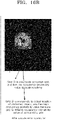
- the detection sensor in accordance with the present embodiment may be implemented as a radar sensor. As illustrated in FIG. 17 , a shaded area where the radar sensor cannot detect an outside object occurs due to the FoV and mounting characteristics (mounting angle and position) of the radar sensor.
- control unit 200 may operate to correct the shaded grid by using a first method of receiving an occupancy probability parameter in the (K-1) th frame or a second method of receiving an occupancy probability parameter of a grid around the shaded grid.
- the first method may be performed when the speed of the vehicle is equal to or higher than a preset reference value.
- a grid 1 in the (K-1) th frame does not correspond to a shaded grid, and thus retains with an occupancy probability parameter.
- the update process for the grid map is performed, and the grid 1 in the K th frame belongs to the shaded grids.
- the control unit 200 may set the occupancy probability parameter of the grid 1 in the (K-1) th frame to the occupancy probability parameter of the shaded grid 1 in the K th frame, thereby minimizing a loss caused by missing detection of the radar sensor.
- the second method may be performed when the speed of the vehicle is lower than the reference value. That is, when the vehicle travels at a very low speed or is stopped, the grid map is not updated even though the (K-1) th frame is switched to the K th frame. Thus, the first method cannot be applied.
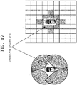
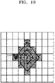
- the control unit 200 may operate to set the occupancy probability parameter of a grid around a shaded grid to the occupancy probability parameter of the shaded grid. In this case, as illustrated in FIG. 19 , the control unit 200 may perform the second method from a shaded grid located at the outermost position, in order to acquire the occupancy probability parameter of a grid which is not the shaded grid.
- the control unit 200 may set the highest occupancy probability parameter, among the occupancy probability parameters of grids located within a preset range (e.g. one grid) from the shaded grid, to the occupancy probability parameter of the corresponding shaded grid.
- FIGS. 20A and 20B show a result obtained by setting an occupancy probability parameter with a predetermined value to a shaded grid through the correction for the shaded area.
- control unit 200 may operate to specify the grid at which the stationary object is highly likely to be located, on the basis of the occupancy probability parameters of the grids within the expanded mapping area.
- control unit 200 may decide a peak grid having the highest occupancy probability parameter among the grids within the expanded mapping area decided for a plurality of frames to be monitored.
- the control unit 200 may determine that the stationary object is located at the peak grid.
- the control unit 200 may monitor the surrounding environment of the vehicle by repeatedly performing the stationary object location decision method based on the 'peak detection', while the vehicle travels.
- FIG. 21 is a flowchart for describing a method for monitoring the surrounding environment of a vehicle in accordance with an embodiment of the present disclosure. The method for monitoring the surrounding environment of a vehicle in accordance with the present embodiment will be described with reference to FIG. 21 .
- the descriptions of contents overlapping the above-described contents will be omitted herein, and the following descriptions will be focused on a time series configuration.
- control unit 200 extracts a stationary object among objects outside the vehicle, detected by the sensor unit 100, by using the behavior information of the vehicle, in step S100.
- control unit 200 maps the stationary object extracted in step S100 to a preset grid map, adds occupancy information to each of grids constituting the grid map according to whether the stationary object is mapped to the grid map, and calculates an occupancy probability parameter from the occupancy information added to the grids within the grid map in a plurality of frames to be monitored, the occupancy probability parameter indicating the probability that the stationary object will be located at the corresponding grid, in step S200.
- step S200 the control unit 200 maps the stationary object to the grid map while updating the grid map by changing the respective indexes of the grids constituting the grid map according to the behavior information of the vehicle.
- step S200 the control unit 200 converts the location information of the stationary object into an index corresponding to the grid map, maps the stationary object to the grid map by specifying a target grid of the grid map, corresponding to the index, adds occupancy information with a first value to the target grid to which the stationary object is mapped, and adds occupancy information with a second value to the other grids, the second value being smaller than the first value.
- step S200 the control unit 200 calculates an occupancy probability parameter by deciding an expanded mapping area expanded by a preset range on the basis of the target grid to which the stationary object is mapped, and adding the occupancy information with the first value to each of grids constituting the expanded mapping area.
- step S200 the control unit 200 corrects the occupancy probability parameters of grids constituting a second expanded mapping area by comparing a first expanded mapping area in the (K-1) th frame to the second expanded mapping area in the K th frame, when the grid map is updated as the (K-1) th frame is switched to the K th frame.
- the control unit 200 specifies a first area composed of grids whose occupancy probability parameters have increased, among the grids of the second expanded mapping area, and a second area composed of grids whose occupancy probability parameters have decreased, among the grids of the first expanded mapping area, on the basis of the K th frame over the (K-1) th frame.
- the control unit 200 corrects the respective occupancy probability parameters of the grids constituting the second expanded mapping area in the K th frame by substituting the occupancy probability parameters of the second area with the occupancy probability parameters of the first area.
- step S200 the control unit 200 corrects a shaded grid corresponding to a shaded area where the sensor unit 100 cannot detect an outside object in the K th frame, by using a first method of receiving an occupancy probability parameter in the (K-1) th frame or a second method of receiving an occupancy probability parameter of a grid around the shaded grid.
- the control unit 200 corrects the shaded grid according to the first method when the speed of the vehicle is equal to or higher than a preset reference value, and corrects the shaded grid according to the second method when the speed of the vehicle is lower than the reference value.
- the control unit 200 monitors the surrounding environment of the vehicle on the basis of the occupancy probability parameter calculated in step S200, in step S300. Specifically, the control unit 200 decides a peak grid having the highest occupancy probability parameter among the grids within the expanded mapping area decided for a plurality of frames to be monitored. When the occupancy probability parameter of the peak grid is equal to or larger than a threshold value defined for the peak grid, the control unit 200 determines that the stationary object is located at the peak grid.
- the apparatus and method for monitoring the surrounding environment of a vehicle in accordance with the present embodiment may map a stationary object detected through the radar to the preset grid map, add occupancy information to each of the grids constituting the grid map depending on whether the stationary object is mapped to the grid map, and then calculate the occupancy probability parameter from the occupancy information added to each of the grids within the grid map in a plurality of frames to be monitored, the occupancy probability parameter indicating that the probability that the stationary object will be located at the corresponding grid, in order to monitor the surrounding environment of the vehicle.
- the apparatus and method can improve the detection accuracy for the outside object when monitoring the surrounding environment of the vehicle through the radar.
- the embodiments described in this specification may be implemented with a method or process, a device, a software program, a data stream or a signal, for example.
- a feature is discussed only in a single context (for example, discussed only in a method), the discussed feature can be implemented in another type (for example, apparatus or program).
- An apparatus may be implemented in suitable hardware, software or firmware.
- the method can be implemented in a device such as a processor which generally refers to a processing device including a computer, a microprocessor, an integrated circuit or a programmable logic device.
- the processor also includes a communication device, such as a computer, cellular phone, PDA (Personal Digital Assistant) and another device, which facilitates information communication between end users.
- a communication device such as a computer, cellular phone, PDA (Personal Digital Assistant) and another device, which facilitates information communication between end users.
Abstract
An apparatus for monitoring the surrounding environment of a vehicle may include: a sensor unit including a plurality of detection sensors configured to detect an object outside the vehicle according to frames with a predefined period; and a control unit configured to extract a stationary object among outside objects detected through the sensor unit by using behavior information of the vehicle, map the extracted stationary object to a preset grid map, add occupancy information to each of grids constituting the grid map depending on whether the stationary object is mapped to the grid map, calculate an occupancy probability parameter indicating the probability that the stationary object will be located at each of the grids, from the occupancy information added to the grids within the grid map in a plurality of frames, and monitor the surrounding environment of the vehicle on the basis of the calculated occupancy probability parameter.
Description
- Exemplary embodiments of the present disclosure relate to an apparatus and method for monitoring the surrounding environment of a vehicle, and more particularly, to an apparatus and method for monitoring the surrounding environment of a vehicle by using an OGM (Occupancy Grid Map).
- A radar for a vehicle refers to a device that detects an outside object within a detection area when the vehicle travels, and warns a driver to help the driver to safely drive the vehicle.
FIGS. 1A and1B illustrate areas to which general radars for a vehicle transmit radar signals to detect an outside object. The radar for a vehicle operates to transmit a radar signal according to a frame with a predefined period, and detect an outside object. As illustrated inFIG. 1B , the signal characteristics of the transmitted radar signal, such as a waveform, frequency, distance resolution, angle resolution, maximum sensing distance, and FoV (Field of View), are different depending on a system of the vehicle, to which the radar is applied. Examples of the system include a DAS (Driver Assistance System) such as BSD (Blind Spot Detection), LCA (Lane Change Assistance), or RCTA (Rear Cross Traffic Alert). - The related art of the present disclosure is disclosed in
Korean Patent Application Laid-Open No. 10-2013-0130843 published on December 2, 2013 - Various embodiments are directed to an apparatus and method for monitoring the surrounding environment of a vehicle, which can improve detection accuracy for an outside object when monitoring the surrounding environment of the vehicle through a radar.
- In an embodiment, there is provided an apparatus for monitoring a surrounding environment of a vehicle, which includes a sensor unit including a plurality of detection sensors for detecting an object outside a vehicle according to a frame at a predefined period, and a control unit configured to extract a stationary object from among the outside objects detected by the sensor unit, to map the extracted stationary object to a preset grid map, to calculate an occupancy probability parameter indicative of a probability that the stationary object will be located on a grid of the grid map from the result of mapping, and to monitor the surrounding environment of the vehicle based on the calculated occupancy probability parameter. The control unit maps the extracted stationary object to the grid map while updating the grid map by changing an index of each of grids constituting the grid map according to behavior information of the vehicle.
- The control unit may update the grid map from a (K-1)th frame to a Kth frame when a predefined grid map update condition is satisfied according to a longitudinal or transverse movement distance of the vehicle.
- The grid map update condition may be a condition in which the longitudinal movement distance of the vehicle is greater than the longitudinal size of the grid or the transverse movement distance of the vehicle is greater than the transverse size of the grid.
- The control unit may update the grid map by changing the index of each grid in the (K-1)th frame with respect to the Kth frame based on the longitudinal movement distance, transverse movement distance, and longitudinal angle change of the vehicle.
- The control unit may update the grid map using a rotation matrix that rotates the grid map according to the longitudinal and transverse movement distances of the vehicle from the (K-1)th frame to the Kth frame, the index of each grid in the (K-1)th frame, and the yaw rate of the vehicle.
- The control unit may convert location information of the extracted stationary object into an index corresponding to the grid map, and map the extracted stationary object to the grid map by specifying a target grid of the grid map corresponding to the converted index.
- The control unit may add occupancy information with a first value to the target grid to which the stationary object is mapped, and add occupancy information with a second value to the remaining grids, the second value being smaller than the first value.
- The control unit may determine an expanded mapping area expanded by a set range with respect to the target grid to which the stationary object is mapped, and monitor the surrounding environment of the vehicle by adding the occupation information with the first value to each of grids constituting the expanded mapping area to calculate the occupation probability parameter.
- The set range may be predefined according to distance and speed resolutions of signal waveforms transmitted from the detection sensors.
- The control unit may update the grid map according to whether a predefined grid map update condition is satisfied when switching from a (K-1)th frame to a Kth frame, while correcting a grid map update error due to an error inherent in a factor for determining whether the grid map update condition is satisfied.
- When the grid map update error is corrected as the grid map is updated by switching from the (K-1)th frame to the Kth frame, the control unit may compare a first expanded mapping area extended by a set range with respect to the target grid to which the stationary object is mapped in the (K-1)th frame with a second expanded mapping area extended by a set range with respect to the target grid to which the stationary object is mapped in the Kth frame so as to correct an occupancy probability parameter of each of grids constituting the second expanded mapping area.
- The control unit may specify a first area composed of grids with increased occupancy probability parameters, among the grids of the second expanded mapping area, with respect to the Kth frame compared to the (K-1)th frame, specify a second area composed of grids with decreased occupancy probability parameters, among the grids of the first expanded mapping area, and then replace the occupancy probability parameters of the second area with the occupation probability parameters of the first area to correct the occupancy probability parameter of each of the grids constituting the second expanded mapping area.
- The control unit may determine a peak grid with a maximum occupancy probability parameter among the grids in the grid map, and determine that the stationary object is located on the peak grid when the occupancy probability parameter of the peak grid is equal to or greater than a threshold value defined for the peak grid.
- In another embodiment, there provided a method of monitoring a surrounding environment of a vehicle, which includes extracting, by a control unit, a stationary object from among objects, outside a vehicle, detected by a sensor unit including a plurality of detection sensors for detecting the outside objects of the vehicle according to a frame at a predefined period, mapping, by the control unit, the extracted stationary object to a preset grid map and calculating, by the control unit, an occupancy probability parameter indicative of a probability that the stationary object will be located on a grid of the grid map from the result of mapping, and monitoring, by the control unit, the surrounding environment of the vehicle based on the calculated occupancy probability parameter. The grid map has a longitudinal axis, a transverse axis, and an index set with respect to the vehicle, and in the calculating, by the control unit, an occupancy probability parameter, the control unit maps the extracted stationary object to the grid map while updating the grid map by changing an index of each of grids constituting the grid map according to behavior information of the vehicle.
- In a further embodiment, there is provided an apparatus for monitoring a surrounding environment of a vehicle, which includes a sensor unit including a plurality of detection sensors for detecting an object outside a vehicle according to a frame at a predefined period, and a control unit configured to extract a stationary object from among the outside objects detected by the sensor unit, to map the extracted stationary object to a preset grid map, to calculate an occupancy probability parameter indicative of a probability that the stationary object will be located on a grid of the grid map from the result of mapping, and to monitor the surrounding environment of the vehicle by comparing the calculated occupancy probability parameter with a threshold value defined in the grid of the grid map. The threshold value is defined for each of a plurality of areas in the grid map divided according to whether detection areas overlap each other in each frame for the same detection sensor and whether detection areas overlap each other in the same frame for two adjacent detection sensors.
- The threshold value may be determined by a radar equation in response to strength of a received signal input to the sensor unit.
- The plurality of areas may include an independent area, which has a first threshold value and is defined as an area in the grid map sensed by a first detection sensor in a Kth frame (where K is a natural number).
- The plurality of areas may include a single overlap area, which has a second threshold value and is defined as an area in the grid map where an area sensed by the first detection sensor overlaps the independent area in a (K+1)th frame following the Kth frame.
- The plurality of areas may include a multiple overlap area, which has a third threshold value and is defined as an area in the grid map where an area sensed by a second detection sensor adjacent to the first detection sensor overlaps the single overlap area in the Kth frame or the (K+1)th frame.
- Each of the first to third threshold values may have a linear section, which is a section that linearly increases in response to the strength of the received signal input to the sensor unit, and a relationship of "first threshold value < second threshold value < third threshold value" may be established in a section where the respective linear sections of the first to third threshold values overlap each other.
- In accordance with the embodiments of the present disclosure, the apparatus and method for monitoring the surrounding environment of a vehicle in accordance with the present embodiment may map a stationary object detected through the radar to the preset grid map, add occupancy information to each of the grids constituting the grid map depending on whether the stationary object is mapped to the grid map, and then calculate the occupancy probability parameter from the occupancy information added to each of the grids within the grid map in a plurality of frames to be monitored, the occupancy probability parameter indicating that the probability that the stationary object will be located at the corresponding grid, in order to monitor the surrounding environment of the vehicle. Thus, the apparatus and method can improve the detection accuracy for the outside object when monitoring the surrounding environment of the vehicle through the radar.
-
-
FIGS. 1A and1B are diagrams illustrating areas to which general radars for a vehicle transmit radar signals to detect an outside object. -
FIG. 2 is a block configuration diagram for describing an apparatus for monitoring the surrounding environment of a vehicle in accordance with an embodiment of the present disclosure. -
FIG. 3 is a diagram illustrating a grid map in the apparatus for monitoring the surrounding environment of a vehicle in accordance with the embodiment of the present disclosure. -
FIGS. 4 to 8 are diagrams illustrating a process of setting threshold values of the grid map in the apparatus for monitoring the surrounding environment of a vehicle in accordance with the embodiment of the present disclosure. -
FIGS. 9 and10 are diagrams illustrating a process of updating the grid map in the apparatus for monitoring the surrounding environment of a vehicle in accordance with the embodiment of the present disclosure. -
FIG. 11 is a diagram illustrating a process of mapping a stationary object to the grid map in the apparatus for monitoring the surrounding environment of a vehicle in accordance with the embodiment of the present disclosure. -
FIGS. 12 to 14 are diagrams illustrating a process of deciding an expanded mapping area in the apparatus for monitoring the surrounding environment of a vehicle in accordance with the embodiment of the present disclosure. -
FIGS. 15 and16 are diagrams illustrating a process of correcting an occupancy probability parameter in the apparatus for monitoring the surrounding environment of a vehicle in accordance with the embodiment of the present disclosure. -
FIGS. 17 to 20 are diagrams illustrating a process of correcting a shaded grid in the apparatus for monitoring the surrounding environment of a vehicle in accordance with the embodiment of the present disclosure. - Hereinafter, n apparatus and method for monitoring the surrounding environment of a vehicle will be described below with reference to the accompanying drawings through various exemplary embodiments. It should be noted that the drawings are not to precise scale and may be exaggerated in thickness of lines or sizes of components for descriptive convenience and clarity only. Furthermore, the terms as used herein are defined by taking functions of the invention into account and can be changed according to the custom or intention of users or operators. Therefore, definition of the terms should be made according to the overall disclosures set forth herein.
-
FIG. 2 is a block configuration diagram for describing an apparatus for monitoring the surrounding environment of a vehicle in accordance with an embodiment of the present disclosure,FIG. 3 is a diagram illustrating a grid map in the apparatus for monitoring the surrounding environment of a vehicle in accordance with the embodiment of the present disclosure,FIGS. 4 to 8 are diagrams illustrating a process of setting threshold values of the grid map in the apparatus for monitoring the surrounding environment of a vehicle in accordance with the embodiment of the present disclosure,FIGS. 9 and10 are diagrams illustrating a process of updating the grid map in the apparatus for monitoring the surrounding environment of a vehicle in accordance with the embodiment of the present disclosure,FIG. 11 is a diagram illustrating a process of mapping a stationary object to the grid map in the apparatus for monitoring the surrounding environment of a vehicle in accordance with the embodiment of the present disclosure,FIGS. 12 to 14 are diagrams illustrating a process of deciding an expanded mapping area in the apparatus for monitoring the surrounding environment of a vehicle in accordance with the embodiment of the present disclosure,FIGS. 15 and16 are diagrams illustrating a process of correcting an occupancy probability parameter in the apparatus for monitoring the surrounding environment of a vehicle in accordance with the embodiment of the present disclosure, andFIGS. 17 to 20 are diagrams illustrating a process of correcting a shaded grid in the apparatus for monitoring the surrounding environment of a vehicle in accordance with the embodiment of the present disclosure. - Referring to
FIG. 2 , the apparatus for monitoring the surrounding environment of a vehicle in accordance with the embodiment of the present disclosure may include asensor unit 100 and acontrol unit 200. - The
sensor unit 100 may include first tofourth detection sensors FIG. 2 , thefirst detection sensor 110 may correspond to a rear right (RR) radar sensor, thesecond detection sensor 120 may correspond to a rear left (RL) radar sensor, thethird detection sensor 130 may correspond to a front right (FR) radar sensor, and thefourth detection sensor 140 may correspond to a front left (FL) radar sensor. Therefore, thedetection sensors FIGS. 1A and1B , the waveform, frequency, distance resolution, angle resolution, maximum sensing distance, and FoV of a radar signal transmitted from the radar sensor may have different characteristics for the respective frames. - The
control unit 200 serves to monitor the surrounding environment of the vehicle by controlling an operation of the DAS of the vehicle, and may be implemented as an ECU (Electronic Control Unit), processor, CPU (Central Processing Unit) or SoC (System on Chip). Thecontrol unit 200 may drive an operating system or application to control a plurality of hardware components or software components connected to thecontrol unit 200, and perform various data processing operations. - In the present embodiment, the
control unit 200 may operate to extract a stationary object among outside objects detected by thesensor unit 100 by using behavior information of the vehicle, map the extracted stationary object to a preset grid map, and add occupancy information to each of grids constituting the grid map depending on whether the stationary object is mapped to the grid map. Furthermore, thecontrol unit 200 may operate to calculate an occupancy probability parameter indicating the probability that the stationary object will be located at each of the grids, from the occupancy information added to the grids within the grid map in a plurality of frames to be monitored, and monitor the surrounding environment of the vehicle on the basis of the calculated occupancy probability parameter. - Hereafter, the process of monitoring the surrounding environment of the vehicle will be described in detail for each of the detailed operations of the
control unit 200. - First, the
control unit 200 may extract a stationary object among outside objects detected by thesensor unit 100 by using behavior information of the vehicle and object information acquired on the basis of a result obtained by detecting the outside objects through thesensor unit 100. That is, the descriptions of the present embodiment will be focused on the configuration for monitoring a stationary object, not a moving object, among various outside objects around the vehicle. - The behavior information of the vehicle may include a vehicle speed, yaw rate, speed change information, and steering angle, and the object information may include the number of outside objects detected by the
sensor unit 100, the longitudinal distance and horizontal distance to each of the objects, the longitudinal speed and horizontal speed of each of the objects, and the intensity of a received signal. Thecontrol unit 200 may extract only a stationary object among the outside objects by using the behavior information of the vehicle and the object information. For example, thecontrol unit 200 may distinguish between a moving object and a stationary object by analyzing the relationships between the vehicle speed of the vehicle and the longitudinal/horizontal speeds of the objects, in order to extract only the stationary object. - When the stationary object is extracted, the
control unit 200 may map the extracted stationary object to the preset grid map. Before the mapping process for the stationary object, the grid map and an update process for the grid map will be preferentially described. - As illustrated in
FIG. 3 , the grid map may be set in thecontrol unit 200 in advance, and have a size corresponding to the surrounding environment area of the vehicle, which is to be monitored. InFIG. 3 , Xmap_max represents the maximum distance in the longitudinal direction (the longitudinal size of the grid map), Ymap_max represents the maximum distance in the horizontal direction (the horizontal size of the grid map), Xmap_min represents a longitudinal reference position of the grid map, Ymap_min represents a horizontal reference position of the grid map, Xmap_step represents the longitudinal size of each grid, and Ymap_step represents the horizontal size of each grid. - The longitudinal and horizontal axes of the grid map may be set on the basis of the vehicle. If the longitudinal and horizontal axes of the grid map are set on the basis of a specific point, not the vehicle, more memory resources may be required depending on the mileage of the vehicle. Furthermore, it is effective to set, to the surrounding area of the vehicle, a surrounding environment monitoring area required for outputting a warning to a driver or performing a traveling control operation of the vehicle. Therefore, the longitudinal and horizontal axes of the grid map may be set on the basis of the vehicle. Thus, the indexes (coordinates (i, j)) of the grids constituting the grid map may also be set on the basis of the vehicle, where i and j represent the longitudinal and horizontal indexes, respectively.
- As illustrated in
FIG. 4 , a threshold value for deciding whether a stationary object occupies each of the grids within the grid map may be defined for the corresponding grid in the grid map. As will be described below, the threshold value functions as a value which is compared to an occupancy probability parameter, and serves as a reference value for determining whether the stationary object is located at the corresponding grid. The threshold value may be defined for each of the grids on the basis of a mathematical model according to the intensity of a received signal inputted to thesensor unit 100, and the mathematical model may correspond to a well-known radar equation below, where Pr represents the intensity of the received signal, Gt represents an antenna gain, and Rt represents the distance to the object:
- Specifically, according to the radar equation, the intensity of the received signal may differ depending on the antenna gain and the relative distance to the object. Therefore, the probability that the same object will be detected through the radar may differ depending on the location thereof. For example, when an object is located at a short distance, the intensity of a received signal is so high that the object detection probability increases, and when an object is located at a long distance, the intensity of a received signal is so low that the object detection probability decreases.
- Furthermore, when an object is located at a location where the antenna gain is high, the intensity of a received signal is so high that the object detection probability increases, and when an object is located at a location where the antenna gain is low, the intensity of a received signal is so low that the object sensing detection decreases. As described above, the waveform, frequency, distance resolution, angle resolution, maximum sensing distance, and FoV of a radar signal transmitted from the radar may have different characteristics for the respective frames, depending on the DAS (e.g. BSD, LCA or RCTA) of the vehicle, to which the radar sensor is applied. Thus, each of the frames may include an area where an object can be repeatedly detected, and only a specific frame may include an area where an object can be detected. Therefore, the area which is repeated in each of the frames may have a high object detection probability, and the area which is not repeated in each of the frames may have a low object detection probability. That is because, during two frames, an object can be detected twice in an area which is repeated, but an object can be detected only once in an area which is not repeated.
- Furthermore, for two adjacent radar sensors, for example, the RR radar sensor and the RL radar sensor, there may be an area where an object can be redundantly detected through the two radar sensors, and an area where an object can be detected only through one radar sensor. Therefore, the area where the object can be redundantly detected through the two radar sensors may have a high object detection probability, and the area where the object can be detected only through one radar sensor may have a low object detection probability. That is because, although one radar sensor does not detect the object in the area where the object can be redundantly detected through the two radar sensors, the object can be detected through the other adjacent radar sensor, but when one radar sensor does not detect the object in the area where the object can be detected only through one radar sensor, the object cannot be detected through the other adjacent radar sensor.
- Through the above-described contents, two situations may be considered.
- i) Case in which the object detection probability is the highest: an 'area where an object is located at a short distance and the antenna gain is high', a 'detection area repeated in each frame', and a 'detection area redundant between the adjacent radar sensors'
- i) Case in which the object detection probability is the lowest: an 'area where an object is located at a long distance and the antenna gain is low, a 'detection area which is not repeated in each frame', and a 'detection area which is not redundant between the adjacent radar sensors'
- It may be unreasonable to set the same threshold value to all the grids, in order to decide whether a stationary object occupies each of the grids within the grid map, in the two above cases. That is because, in case (i), it may be falsely determined that an object is present, even though no object is actually present (false detection), and in case (ii), it may be falsely determined that no object is present, even though an object is actually present (missing detection). Thus, in the present embodiment, the threshold values for the respective grids may be differently set depending on the object detection probability, which makes it possible to prevent the false determination (false detection and missing detection).
- Specifically, the threshold value may be set to different values for an independent area, a single-overlap area, and a multi-overlap area within the grid map.
- The independent area may be defined as an area within the grid map, which is sensed by the
first detection sensor 110 in a Kth frame, where K is a natural number, and the single-overlap area may be defined as an area within the grid map, in which an independent area and an area sensed by thefirst detection sensor 110 overlap each other in a (K+1)th frame distinguished from the Kth frame (following the Kth frame). That is, the independent area and the single-overlap area are distinguished from each other, according to whether the detection areas overlap each other for the same detection sensor in the respective frames. InFIG. 5 in which the first detection sensor is the RR radar, the grid of the independent area is designated by '0', and the grid of the single-overlap area is designated by '1'. The threshold value of the grid of the independent area may be set to a lower value than that of the grid of the single-overlap area, which makes it possible to compensate for false detection and missing detection which may occur for an object located in the independent area. - The multi-overlap area may be defined as an area within the grid map, in which an area sensed by the
second detection sensor 120 adjacent to thefirst detection sensor 110 overlaps a single-overlap area in the same frame (Kth or (K+1)th frame). That is, the multi-overlap area is decided according to whether areas detected by two adjacent detection sensors overlap each other in the same frame. InFIG. 6 in which the first detection sensor is the RR radar and the second detection sensor is the RL radar, the grid of an area sensed by thefirst detection sensor 110 is designated by '0', and the grid of the area where areas sensed by the first andsecond detection sensors FIG. 7 in which the first detection sensor is the RR radar and the second detection sensor is the RL radar, the grid map may be divided into the independent area '0' sensed by thefirst detection sensor 110 in the Kth frame, the single-overlap area '1' which is an overlap area between the areas sensed by thefirst detection sensor 110 in the Kth frame and the (K+1)th frame, and the multi-overlap area '2' which is an overlap area sensed by the first andsecond detection sensors FIG. 8 . - As described above, since the longitudinal axis, horizontal index, and indexes of the grid map are set on the basis of the vehicle, the indexes of the grid map are changed by the behavior of the vehicle. Thus, a process of updating the grid map by changing the indexes of the grid map is needed in order to map a stationary object to the grid map. Furthermore, even after the stationary object is mapped to the grid map, the index of the grid to which the stationary object is mapped needs to be changed according to the behavior of the vehicle. When the grid map is updated after the stationary object is mapped to the grid map, the index of the grid to which the stationary object is mapped is also changed.
- For this operation, the
control unit 200 may update the grid map when a longitudinal moving distance of the vehicle is larger than the longitudinal size of the grid or a horizontal moving distance of the vehicle is larger than the horizontal size of the grid during a period from a (K-1)th frame to the Kth frame. In this case, thecontrol unit 200 may change the indexes of the respective grids in the (K-1)th frame from those in the Kth frame, on the basis of the longitudinal moving distance, the horizontal moving distance, and a longitudinal angle change of the vehicle. - In order to take, as an example of a changed index, the index of a grid at which a stationary object is located,
FIG. 9A illustrates the grid map in the (K-1)th frame with the index of the grid at which the stationary object is located. When the vehicle travels in the longitudinal direction by a distance larger than the longitudinal size of the grid as illustrated inFIG. 9B , the index of the stationary index on the grid map in the (K-1)th frame needs to be changed on the basis of the Kth frame, because the index of the stationary object on the grid map in the Kth frame is different from the index of the stationary object on the grid map in the (K-1)th frame. When the vehicle makes a turn according to a predetermined yaw rate as illustrated inFIG. 9C such that the longitudinal or horizontal moving distance of the vehicle becomes smaller than the longitudinal or horizontal size of the grid, the index of the stationary object on the grid map in the (K-1)th frame needs to be changed on the basis of the Kth frame, because the index of the stationary object on the grid map in the Kth frame is different from the index of the stationary object on the grid map in the (K-1)th frame. In this case, an angle change based on the yaw rate may be reflected into the update of the grid map. - The update process for the grid map based on
FIGS. 9A to 9C will be described with reference to modeling ofFIG. 10 . - First, the
control unit 200 calculates the accumulative values of yaw-axis angle changes and moving displacement changes of the vehicle during a period from the (K-1)th frame to the Kth frame, according toEquation 1 below.
- In
Equation 1, Δθ represents a yaw-axis reference instantaneous angle change of the vehicle, Δθ_acc represents a yaw-axis reference accumulative angle change during the period from the (K-1)th frame to the Kth frame, Δγ represents an instantaneous moving displacement of the vehicle, Vs represents the speed of the vehicle, dt represents a time period from the (K-1)th frame to the Kth frame, represents a longitudinal unit vector, represents a horizontal unit vector, and Δγ_acc represents an accumulative moving displacement of the vehicle during the period from the (K-1)th frame to the Kth frame. - The
control unit 200 determines whether a grid map update condition is satisfied, according toEquation 2 below.
- In
Equation 2, Δxk represents a longitudinal instantaneous moving distance of the vehicle, Δyk represents a horizontal instantaneous moving distance of the vehicle, Δxk_acc represents a longitudinal accumulative moving distance of the vehicle, and Δyk_acc represents a horizontal accumulative moving distance of the vehicle. - When the grid map update condition is satisfied according to
Equation 2, thecontrol unit 200 updates the grid map according toEquation 3 below.
- In
Equation 3, (i, i) represents the index of a grid, (i_update, j_update) represents the index of an updated grid, and floor represents a truncation operator. InEquation 3, the matrix functions as a rotation matrix for rotating the grid map according to the yaw rate of the vehicle: - The
control unit 200 may convert the location information of a stationary object, i.e. the longitudinal distance and horizontal distance to the stationary object, into an index corresponding to the (updated) grid map, according to Equation 4 below.
- In Equation 4, Itgt_n represents the longitudinal index of a target grid, Jtgt_n represents the horizontal index of the target grid, Xtgt_n represents the longitudinal distance to the stationary object, and Ytgt_n represents the horizontal distance to the stationary object.
- As illustrated in
FIG. 11 , thecontrol unit 200 may map an extracted stationary object to the grid map by specifying a target grid of the grid map, corresponding to a changed index. In this case, thecontrol unit 200 may add occupancy information having a first value to the target grid to which the stationary object is mapped, and add occupancy information having a second value to the other grids. In the present embodiment, the first value may be set to '1', and the second value may be set to '0'. Thus, the value '1' may be added as the occupancy information to the target grid to which the stationary object is mapped, and the value '0' may be added as the occupancy information to the other grids to which the stationary object is not mapped. Hereafter, the occupancy information added to an index (i, j) in the Kth frame will be represented by Pmap (i, j, k). - As described above, the waveform, frequency, distance resolution, angle resolution, maximum sensing distance, and FoV of a radar signal transmitted from a radar sensor may have different characteristics for the respective frames, depending on the DAS (e.g. BSD, LCA or RCTA) of the vehicle, to which the radar sensor is applied. Therefore, although the same stationary object is detected, the index at which the stationary object is detected may be changed in each frame because the signal characteristics are different in each frame. In this case, an occupancy probability parameter to be described below may be reduced by the number of used signal waveforms.
FIG. 12 illustrates results obtained when the radar sensor detects the same stationary object by transmitting radar signals with a single waveform and multiple waveforms. In the case of the multiple waveforms, grids occupied in the respective frames are distributed to reduce the probability that the stationary object will be detected, compared to the single waveform. When the threshold value of the grid map is set to a low value to compensate for the reduction in the occupancy probability parameter, the stationary object is highly likely to be falsely detected due to a clutter or noise. - In order to prevent the false detection, the
control unit 200 in accordance with the present embodiment may add occupancy information to surrounding grids as well as the target grid corresponding to the detected stationary object. Specifically, as illustrated inFIG. 13 , thecontrol unit 200 may decide an expanded mapping area, which is expanded by a preset range on the basis of the target grid to which the stationary object is mapped, and calculate the occupancy probability parameter by adding the occupancy information with the first value to each of the grids constituting the expanded mapping area, in order to monitor the surrounding environment of the vehicle. The preset range expanded from the target grid may be defined in advance by a designer, in consideration of the similarity (distance resolution and speed resolution) between the signal waveforms. -
FIG. 14 illustrates results obtained when the radar sensor detects the same stationary object by transmitting radar signals with a single waveform and multiple waveforms. After the expanded mapping area expanded by the present range from the target grid is set, the reduction in the probability that the stationary object will be detected may be removed even in the case of the multiple waveforms, through the following method of calculating the occupancy probability parameter for each of the grids constituting the expanded mapping area. - The process of calculating the occupancy probability parameter of the grid map in the present embodiment follows an occupancy probability calculation method of a general OGM (Occupancy Grid Map) based on Equation 5 below.

- In Equation 5, R1:k represents the sensing data (the above-described object information) of the sensor unit 100 (radar sensor) from the first frame to the Kth frame, and V1:k represents the behavior data (the above-described behavior information) of the vehicle from the first frame to the Kth frame, and 10 represents a prior probability (0 in the present embodiment).
- When the occupancy information Pmap (i, j, k) added to each of the grids in the present embodiment is applied to the occupancy probability calculation method based on Equation 5 above, an occupancy probability parameter p is calculated according to Equation 6 below.

- In Equation 6, M represents the number of frames to be monitored.
- The speed, moving displacement, and yaw-axis angle change of the vehicle, which serve as factors for determining whether the update condition of the grid map is satisfied, are acquired by the sensors applied to the vehicle. Since such sensing values inevitably contain an error, it may be determined that the update condition of the grid map has been satisfied even though the update condition of the grid map was not actually satisfied, due to the error contained in the sensing values. In this case, the grid map may be falsely updated. As described above, during the update process for the grid map, the
control unit 200 operates to change the index of the target grid to which the stationary object is mapped. Thus, when the grid map is falsely updated, an error may occur between the index corresponding to the actual location of the stationary object and the index of the stationary object mapped to the falsely updated grid map. As a result, the error may cause false detection and missing detection for the stationary object. - The occurrence of the error will be described with reference to
FIGS. 15A to 15D. FIG. 15A illustrates that a stationary object is mapped to agrid ① in the (K-1)th frame, and then thegrid ① is expanded by a preset range to decide a first expanded mapping area, andFIG. 15B illustrates that the update condition of the above-described grid map is satisfied in the Kth frame, such that the grid map is updated. Since the grid map has been updated, the index of the grid to which the stationary object is mapped is also changed, so that the grid to which the stationary object is mapped is updated into agrid ②. Furthermore, the location of the stationary object, which has been actually detected by thesensor unit 100, is still maintained at thegrid ①. As a result, an error occurs between the index of the grid corresponding to the actual location of the stationary object and the index of the grid of the stationary object mapped to the updated grid map. - When the grid map is updated as the (K-1)th frame is switched to the Kth frame, the
control unit 200 may correct the respective occupancy probability parameters of the grids constituting a second expanded mapping area through a method of comparing the first expanded mapping area in the (K-1)th frame to the second expanded mapping area in the Kth frame, thereby correcting the above-described update error. - Referring to
FIG. 15C , thecontrol unit 200 may specify a first area composed of grids whose occupancy probability parameters have increased, among the grids of the second expanded mapping area, on the basis of the Kth frame over the (K-1)th frame. That is, the first area corresponds to grids which were not occupied in the (K-1)th frame, but are occupied in the Kth frame. Furthermore, thecontrol unit 200 may specify a second area composed of grids whose occupancy probability parameters have decreased, among the grids of the first expanded mapping area, on the basis of the Kth frame over the (K-1)th frame. That is, the second area corresponds to grids which were occupied in the (K-1)th frame, but are not occupied in the Kth frame. Furthermore, thecontrol unit 200 may correct the respective occupancy probability parameters of the grids constituting the second expanded mapping area in the Kth frame by substituting the occupancy probability parameters of the second area with the occupancy probability parameters of the first area. Thus, as illustrated inFIG. 15D , the expanded mapping area may be configured while being matched with the location of the stationary object, which is actually detected by thesensor unit 100. When the state in which the grids constituting the second area are not occupied lasts for a preset time, the occupancy probability parameters of the grids may be reset to '0'. -
FIG. 16A illustrates an example of an occupancy probability parameter on the grid map before an update error of the grid map is updated. As described inFIG. 16A , agrid ① corresponds to a location having horizontal/longitudinal errors from the actual location of a stationary object, but remains with a predetermined occupancy probability value, and agrid ② corresponds to the actual location of the stationary object, but has a lower occupancy probability value than surrounding grids, because thegrid ② is a newly occupied grid. -
FIG. 16B illustrates an example of the occupancy probability parameter on the grid map after an update error of the grid map is corrected. As described inFIG. 16B , agrid ① is a previously occupied grid, and has a low occupancy probability value through resetting, and agrid ② corresponds to the actual location of a stationary object, and has a higher occupancy probability value than surrounding grids because thegrid ② is a newly occupied grid, but inherits a predetermined occupancy probability value. - As described above, the detection sensor in accordance with the present embodiment may be implemented as a radar sensor. As illustrated in
FIG. 17 , a shaded area where the radar sensor cannot detect an outside object occurs due to the FoV and mounting characteristics (mounting angle and position) of the radar sensor. - In order to correct a shaded grid corresponding to the shaded area, the
control unit 200 may operate to correct the shaded grid by using a first method of receiving an occupancy probability parameter in the (K-1)th frame or a second method of receiving an occupancy probability parameter of a grid around the shaded grid. - The first method may be performed when the speed of the vehicle is equal to or higher than a preset reference value. As illustrated in
FIG. 18 , agrid ① in the (K-1)th frame does not correspond to a shaded grid, and thus retains with an occupancy probability parameter. When the vehicle speed is equal to or higher than the reference value, the update process for the grid map is performed, and thegrid ① in the Kth frame belongs to the shaded grids. In this case, thecontrol unit 200 may set the occupancy probability parameter of thegrid ① in the (K-1)th frame to the occupancy probability parameter of the shadedgrid ① in the Kth frame, thereby minimizing a loss caused by missing detection of the radar sensor. - The second method may be performed when the speed of the vehicle is lower than the reference value. That is, when the vehicle travels at a very low speed or is stopped, the grid map is not updated even though the (K-1)th frame is switched to the Kth frame. Thus, the first method cannot be applied. In this case, the
control unit 200 may operate to set the occupancy probability parameter of a grid around a shaded grid to the occupancy probability parameter of the shaded grid. In this case, as illustrated inFIG. 19 , thecontrol unit 200 may perform the second method from a shaded grid located at the outermost position, in order to acquire the occupancy probability parameter of a grid which is not the shaded grid. Thecontrol unit 200 may set the highest occupancy probability parameter, among the occupancy probability parameters of grids located within a preset range (e.g. one grid) from the shaded grid, to the occupancy probability parameter of the corresponding shaded grid. FIGS. 20A and 20B show a result obtained by setting an occupancy probability parameter with a predetermined value to a shaded grid through the correction for the shaded area. - When the update of the grid map, the decision of the expanded mapping area, the update error correction, and the shaded area correction are performed through the above-described processes, the
control unit 200 may operate to specify the grid at which the stationary object is highly likely to be located, on the basis of the occupancy probability parameters of the grids within the expanded mapping area. - That is, the
control unit 200 may decide a peak grid having the highest occupancy probability parameter among the grids within the expanded mapping area decided for a plurality of frames to be monitored. When the occupancy probability parameter of the peak grid is equal to or larger than a threshold value defined for the peak grid, thecontrol unit 200 may determine that the stationary object is located at the peak grid. Thecontrol unit 200 may monitor the surrounding environment of the vehicle by repeatedly performing the stationary object location decision method based on the 'peak detection', while the vehicle travels. -
FIG. 21 is a flowchart for describing a method for monitoring the surrounding environment of a vehicle in accordance with an embodiment of the present disclosure. The method for monitoring the surrounding environment of a vehicle in accordance with the present embodiment will be described with reference toFIG. 21 . Hereafter, the descriptions of contents overlapping the above-described contents will be omitted herein, and the following descriptions will be focused on a time series configuration. - First, the
control unit 200 extracts a stationary object among objects outside the vehicle, detected by thesensor unit 100, by using the behavior information of the vehicle, in step S100. - Then, the
control unit 200 maps the stationary object extracted in step S100 to a preset grid map, adds occupancy information to each of grids constituting the grid map according to whether the stationary object is mapped to the grid map, and calculates an occupancy probability parameter from the occupancy information added to the grids within the grid map in a plurality of frames to be monitored, the occupancy probability parameter indicating the probability that the stationary object will be located at the corresponding grid, in step S200. - In step S200, the
control unit 200 maps the stationary object to the grid map while updating the grid map by changing the respective indexes of the grids constituting the grid map according to the behavior information of the vehicle. - Furthermore, in step S200, the
control unit 200 converts the location information of the stationary object into an index corresponding to the grid map, maps the stationary object to the grid map by specifying a target grid of the grid map, corresponding to the index, adds occupancy information with a first value to the target grid to which the stationary object is mapped, and adds occupancy information with a second value to the other grids, the second value being smaller than the first value. - Furthermore, in step S200, the
control unit 200 calculates an occupancy probability parameter by deciding an expanded mapping area expanded by a preset range on the basis of the target grid to which the stationary object is mapped, and adding the occupancy information with the first value to each of grids constituting the expanded mapping area. - Furthermore, in step S200, the
control unit 200 corrects the occupancy probability parameters of grids constituting a second expanded mapping area by comparing a first expanded mapping area in the (K-1)th frame to the second expanded mapping area in the Kth frame, when the grid map is updated as the (K-1)th frame is switched to the Kth frame. Specifically, thecontrol unit 200 specifies a first area composed of grids whose occupancy probability parameters have increased, among the grids of the second expanded mapping area, and a second area composed of grids whose occupancy probability parameters have decreased, among the grids of the first expanded mapping area, on the basis of the Kth frame over the (K-1)th frame. Then, thecontrol unit 200 corrects the respective occupancy probability parameters of the grids constituting the second expanded mapping area in the Kth frame by substituting the occupancy probability parameters of the second area with the occupancy probability parameters of the first area. - Furthermore, in step S200, the
control unit 200 corrects a shaded grid corresponding to a shaded area where thesensor unit 100 cannot detect an outside object in the Kth frame, by using a first method of receiving an occupancy probability parameter in the (K-1)th frame or a second method of receiving an occupancy probability parameter of a grid around the shaded grid. In this case, thecontrol unit 200 corrects the shaded grid according to the first method when the speed of the vehicle is equal to or higher than a preset reference value, and corrects the shaded grid according to the second method when the speed of the vehicle is lower than the reference value. - After step S200, the
control unit 200 monitors the surrounding environment of the vehicle on the basis of the occupancy probability parameter calculated in step S200, in step S300. Specifically, thecontrol unit 200 decides a peak grid having the highest occupancy probability parameter among the grids within the expanded mapping area decided for a plurality of frames to be monitored. When the occupancy probability parameter of the peak grid is equal to or larger than a threshold value defined for the peak grid, thecontrol unit 200 determines that the stationary object is located at the peak grid. - As such, the apparatus and method for monitoring the surrounding environment of a vehicle in accordance with the present embodiment may map a stationary object detected through the radar to the preset grid map, add occupancy information to each of the grids constituting the grid map depending on whether the stationary object is mapped to the grid map, and then calculate the occupancy probability parameter from the occupancy information added to each of the grids within the grid map in a plurality of frames to be monitored, the occupancy probability parameter indicating that the probability that the stationary object will be located at the corresponding grid, in order to monitor the surrounding environment of the vehicle. Thus, the apparatus and method can improve the detection accuracy for the outside object when monitoring the surrounding environment of the vehicle through the radar.
- The embodiments described in this specification may be implemented with a method or process, a device, a software program, a data stream or a signal, for example. Although a feature is discussed only in a single context (for example, discussed only in a method), the discussed feature can be implemented in another type (for example, apparatus or program). An apparatus may be implemented in suitable hardware, software or firmware. The method can be implemented in a device such as a processor which generally refers to a processing device including a computer, a microprocessor, an integrated circuit or a programmable logic device. The processor also includes a communication device, such as a computer, cellular phone, PDA (Personal Digital Assistant) and another device, which facilitates information communication between end users.
- Although exemplary embodiments of the disclosure have been disclosed for illustrative purposes, those skilled in the art will appreciate that various modifications, additions and substitutions are possible, without departing from the scope and spirit of the disclosure as defined in the accompanying claims. Thus, the true technical scope of the disclosure should be defined by the following claims.
Claims (15)
- An apparatus for monitoring a surrounding environment of a vehicle, comprising:a sensor unit comprising a plurality of detection sensors for detecting an object outside a vehicle according to a frame at a predefined period; anda control unit configured to extract a stationary object from among the outside objects detected by the sensor unit, to map the extracted stationary object to a preset grid map, to calculate an occupancy probability parameter indicative of a probability that the stationary object will be located on a grid of the grid map from the result of mapping, and to monitor the surrounding environment of the vehicle based on the calculated occupancy probability parameter,wherein the control unit maps the extracted stationary object to the grid map while updating the grid map by changing an index of each of grids constituting the grid map according to behavior information of the vehicle.
- The apparatus according to claim 1, wherein the control unit updates the grid map from a (K-1)th frame to a Kth frame when a predefined grid map update condition is satisfied according to a longitudinal or transverse movement distance of the vehicle.
- The apparatus according to claim 2, wherein the control unit updates the grid map by changing the index of each grid in the (K-1)th frame with respect to the Kth frame based on the longitudinal movement distance, transverse movement distance, and longitudinal angle change of the vehicle, and
wherein the control unit updates the grid map using a rotation matrix that rotates the grid map according to the longitudinal and transverse movement distances of the vehicle from the (K-1)th frame to the Kth frame, the index of each grid in the (K-1)th frame, and the yaw rate of the vehicle. - The apparatus according to any one of claims 1 to 3, wherein the control unit converts location information of the extracted stationary object into an index corresponding to the grid map, and maps the extracted stationary object to the grid map by specifying a target grid of the grid map corresponding to the converted index.
- The apparatus according to claim 4, wherein the control unit adds occupancy information with a first value to the target grid to which the stationary object is mapped, and adds occupancy information with a second value to the remaining grids, the second value being smaller than the first value, and
wherein the control unit determines an expanded mapping area expanded by a set range with respect to the target grid to which the stationary object is mapped, and monitors the surrounding environment of the vehicle by adding the occupation information with the first value to each of grids constituting the expanded mapping area to calculate the occupation probability parameter. - The apparatus according to any one of claims 1 to 5, wherein the control unit updates the grid map according to whether a predefined grid map update condition is satisfied when switching from a (K-1)th frame to a Kth frame, while correcting a grid map update error due to an error inherent in a factor for determining whether the grid map update condition is satisfied.
- The apparatus according to claim 6, wherein, when the grid map update error is corrected as the grid map is updated by switching from the (K-1)th frame to the Kth frame, the control unit compares a first expanded mapping area extended by a set range with respect to the target grid to which the stationary object is mapped in the (K-1)th frame with a second expanded mapping area extended by a set range with respect to the target grid to which the stationary object is mapped in the Kth frame so as to correct an occupancy probability parameter of each of grids constituting the second expanded mapping area.
- The apparatus according to claim 7, wherein the control unit specifies a first area composed of grids with increased occupancy probability parameters, among the grids of the second expanded mapping area, with respect to the Kth frame compared to the (K-1)th frame, specifies a second area composed of grids with decreased occupancy probability parameters, among the grids of the first expanded mapping area, and then replaces the occupancy probability parameters of the second area with the occupation probability parameters of the first area to correct the occupancy probability parameter of each of the grids constituting the second expanded mapping area.
- The apparatus according to any one of claims 1 to 8, wherein the control unit determines a peak grid with a maximum occupancy probability parameter among the grids in the grid map, and determines that the stationary object is located on the peak grid when the occupancy probability parameter of the peak grid is equal to or greater than a threshold value defined for the peak grid.
- A method of monitoring a surrounding environment of a vehicle, comprising:extracting, by a control unit, a stationary object from among objects, outside a vehicle, detected by a sensor unit comprising a plurality of detection sensors for detecting the outside objects of the vehicle according to a frame at a predefined period;mapping, by the control unit, the extracted stationary object to a preset grid map and calculating, by the control unit, an occupancy probability parameter indicative of a probability that the stationary object will be located on a grid of the grid map from the result of mapping; andmonitoring, by the control unit, the surrounding environment of the vehicle based on the calculated occupancy probability parameter, wherein:the grid map has a longitudinal axis, a transverse axis, and an index set with respect to the vehicle; andin the calculating, by the control unit, an occupancy probability parameter, the control unit maps the extracted stationary object to the grid map while updating the grid map by changing an index of each of grids constituting the grid map according to behavior information of the vehicle.
- An apparatus for monitoring a surrounding environment of a vehicle, comprising:a sensor unit comprising a plurality of detection sensors for detecting an object outside a vehicle according to a frame at a predefined period; anda control unit configured to extract a stationary object from among the outside objects detected by the sensor unit, to map the extracted stationary object to a preset grid map, to calculate an occupancy probability parameter indicative of a probability that the stationary object will be located on a grid of the grid map from the result of mapping, and to monitor the surrounding environment of the vehicle by comparing the calculated occupancy probability parameter with a threshold value defined in the grid of the grid map,wherein the threshold value is defined for each of a plurality of areas in the grid map divided according to whether detection areas overlap each other in each frame for the same detection sensor and whether detection areas overlap each other in the same frame for two adjacent detection sensors.
- The apparatus according to claim 11, wherein the plurality of areas comprise an independent area, which has a first threshold value and is defined as an area in the grid map sensed by a first detection sensor in a Kth frame (where K is a natural number).
- The apparatus according to claim 12, wherein the plurality of areas comprise a single overlap area, which has a second threshold value and is defined as an area in the grid map where an area sensed by the first detection sensor overlaps the independent area in a (K+1)th frame following the Kth frame.
- The apparatus according to claim 13, wherein the plurality of areas comprise a multiple overlap area, which has a third threshold value and is defined as an area in the grid map where an area sensed by a second detection sensor adjacent to the first detection sensor overlaps the single overlap area in the Kth frame or the (K+1)th frame.
- The apparatus according to claim 14, wherein each of the first to third threshold values has a linear section, which is a section that linearly increases in response to the strength of the received signal input to the sensor unit, and a relationship of "first threshold value < second threshold value < third threshold value" is established in a section where the respective linear sections of the first to third threshold values overlap each other.
Applications Claiming Priority (4)
| Application Number | Priority Date | Filing Date | Title |
|---|---|---|---|
| KR1020210095588A KR20230014350A (en) | 2021-07-21 | 2021-07-21 | Apparatus amd method for monitoring surrounding environment of vehicle |
| KR1020210095586A KR20230014348A (en) | 2021-07-21 | 2021-07-21 | Apparatus amd method for monitoring surrounding environment of vehicle |
| KR1020210095591A KR20230014352A (en) | 2021-07-21 | 2021-07-21 | Apparatus amd method for monitoring surrounding environment of vehicle |
| KR1020210095587A KR20230014349A (en) | 2021-07-21 | 2021-07-21 | Apparatus amd method for monitoring surrounding environment of vehicle |
Publications (1)
| Publication Number | Publication Date |
|---|---|
| EP4123336A1 true EP4123336A1 (en) | 2023-01-25 |
Family
ID=82595086
Family Applications (1)
| Application Number | Title | Priority Date | Filing Date |
|---|---|---|---|
| EP22184734.6A Pending EP4123336A1 (en) | 2021-07-21 | 2022-07-13 | Apparatus and method for monitoring surrounding environment of vehicle |
Country Status (3)
| Country | Link |
|---|---|
| US (1) | US20230027766A1 (en) |
| EP (1) | EP4123336A1 (en) |
| CN (1) | CN115685207A (en) |
Citations (5)
| Publication number | Priority date | Publication date | Assignee | Title |
|---|---|---|---|---|
| KR20130130843A (en) | 2011-09-26 | 2013-12-02 | 도요타 지도샤(주) | Rear cross traffic alert device |
| US20150284010A1 (en) * | 2013-09-16 | 2015-10-08 | Disney Enterprises, Inc. | Shared control of semi-autonomous vehicles including collision avoidance in multi-agent scenarios |
| WO2019244060A1 (en) * | 2018-06-22 | 2019-12-26 | MAGNETI MARELLI S.p.A. | Method for vehicle environment mapping, corresponding system, vehicle and computer program product |
| US20200103523A1 (en) * | 2018-09-28 | 2020-04-02 | Zoox, Inc. | Radar Spatial Estimation |
| WO2020154965A1 (en) * | 2019-01-30 | 2020-08-06 | Baidu.Com Times Technology (Beijing) Co., Ltd. | A real-time map generation system for autonomous vehicles |
-
2022
- 2022-07-13 EP EP22184734.6A patent/EP4123336A1/en active Pending
- 2022-07-19 CN CN202210850717.XA patent/CN115685207A/en active Pending
- 2022-07-21 US US17/870,203 patent/US20230027766A1/en active Pending
Patent Citations (5)
| Publication number | Priority date | Publication date | Assignee | Title |
|---|---|---|---|---|
| KR20130130843A (en) | 2011-09-26 | 2013-12-02 | 도요타 지도샤(주) | Rear cross traffic alert device |
| US20150284010A1 (en) * | 2013-09-16 | 2015-10-08 | Disney Enterprises, Inc. | Shared control of semi-autonomous vehicles including collision avoidance in multi-agent scenarios |
| WO2019244060A1 (en) * | 2018-06-22 | 2019-12-26 | MAGNETI MARELLI S.p.A. | Method for vehicle environment mapping, corresponding system, vehicle and computer program product |
| US20200103523A1 (en) * | 2018-09-28 | 2020-04-02 | Zoox, Inc. | Radar Spatial Estimation |
| WO2020154965A1 (en) * | 2019-01-30 | 2020-08-06 | Baidu.Com Times Technology (Beijing) Co., Ltd. | A real-time map generation system for autonomous vehicles |
Also Published As
| Publication number | Publication date |
|---|---|
| US20230027766A1 (en) | 2023-01-26 |
| CN115685207A (en) | 2023-02-03 |
Similar Documents
| Publication | Publication Date | Title |
|---|---|---|
| EP4080468A2 (en) | Collision detection method and apparatus, electronic device, medium, and autonomous vehicle | |
| EP3151034B1 (en) | Automated vehicle radar system to determine yaw-rate of a target vehicle | |
| US9500748B2 (en) | Target recognition apparatus | |
| US20220019817A1 (en) | Vehicle locating method, electronic device and storage medium | |
| CN110632617B (en) | Laser radar point cloud data processing method and device | |
| CN112009473B (en) | Method and device for selecting self-adaptive cruise target and computer equipment | |
| CN111144330B (en) | Deep learning-based lane line detection method, device and equipment | |
| CN110007305B (en) | Method, device, server and storage medium for determining vehicle front target | |
| US20190126930A1 (en) | Apparatus for providing map information for determining driving situation of vehicle, system including the same, and method thereof | |
| US11507107B2 (en) | Map information system | |
| WO2018212292A1 (en) | Information processing device, control method, program and storage medium | |
| EP3260878B1 (en) | Moving object detection device, program, and recording medium | |
| CN107991677A (en) | A kind of pedestrian detection method | |
| US20030090409A1 (en) | Radar ranging device for performing merging process on a plurality of detected targets | |
| EP4123336A1 (en) | Apparatus and method for monitoring surrounding environment of vehicle | |
| CN112180364B (en) | Method and device for acquiring surrounding environment of vehicle, electronic equipment and storage medium | |
| EP4095552A1 (en) | Apparatus and method for monitoring surrounding environment of vehicle | |
| US11852716B2 (en) | Apparatus and method for monitoring surrounding environment of vehicle | |
| CN111959515A (en) | Forward target selection method, device and system based on visual detection | |
| EP4123338A2 (en) | Apparatus and method for monitoring surrounding environment of vehicle | |
| CN112733778B (en) | Vehicle front guide determination method and device and computer equipment | |
| KR20230014347A (en) | Apparatus amd method for monitoring surrounding environment of vehicle | |
| KR20230014349A (en) | Apparatus amd method for monitoring surrounding environment of vehicle | |
| KR20230014352A (en) | Apparatus amd method for monitoring surrounding environment of vehicle | |
| KR20230014348A (en) | Apparatus amd method for monitoring surrounding environment of vehicle |
Legal Events
| Date | Code | Title | Description |
|---|---|---|---|
| PUAI | Public reference made under article 153(3) epc to a published international application that has entered the european phase |
Free format text: ORIGINAL CODE: 0009012 |
|
| STAA | Information on the status of an ep patent application or granted ep patent |
Free format text: STATUS: REQUEST FOR EXAMINATION WAS MADE |
|
| 17P | Request for examination filed |
Effective date: 20220713 |
|
| AK | Designated contracting states |
Kind code of ref document: A1 Designated state(s): AL AT BE BG CH CY CZ DE DK EE ES FI FR GB GR HR HU IE IS IT LI LT LU LV MC MK MT NL NO PL PT RO RS SE SI SK SM TR |
|
| STAA | Information on the status of an ep patent application or granted ep patent |
Free format text: STATUS: EXAMINATION IS IN PROGRESS |
|
| 17Q | First examination report despatched |
Effective date: 20230725 |