EP4123249A1 - Automatic water supply apparatus and refrigerator having same - Google Patents
Automatic water supply apparatus and refrigerator having same Download PDFInfo
- Publication number
- EP4123249A1 EP4123249A1 EP20925475.4A EP20925475A EP4123249A1 EP 4123249 A1 EP4123249 A1 EP 4123249A1 EP 20925475 A EP20925475 A EP 20925475A EP 4123249 A1 EP4123249 A1 EP 4123249A1
- Authority
- EP
- European Patent Office
- Prior art keywords
- water
- vessel
- water vessel
- water supply
- supply device
- Prior art date
- Legal status (The legal status is an assumption and is not a legal conclusion. Google has not performed a legal analysis and makes no representation as to the accuracy of the status listed.)
- Granted
Links
Images




Classifications
-
- F—MECHANICAL ENGINEERING; LIGHTING; HEATING; WEAPONS; BLASTING
- F25—REFRIGERATION OR COOLING; COMBINED HEATING AND REFRIGERATION SYSTEMS; HEAT PUMP SYSTEMS; MANUFACTURE OR STORAGE OF ICE; LIQUEFACTION SOLIDIFICATION OF GASES
- F25D—REFRIGERATORS; COLD ROOMS; ICE-BOXES; COOLING OR FREEZING APPARATUS NOT OTHERWISE PROVIDED FOR
- F25D23/00—General constructional features
- F25D23/02—Doors; Covers
- F25D23/04—Doors; Covers with special compartments, e.g. butter conditioners
-
- F—MECHANICAL ENGINEERING; LIGHTING; HEATING; WEAPONS; BLASTING
- F25—REFRIGERATION OR COOLING; COMBINED HEATING AND REFRIGERATION SYSTEMS; HEAT PUMP SYSTEMS; MANUFACTURE OR STORAGE OF ICE; LIQUEFACTION SOLIDIFICATION OF GASES
- F25D—REFRIGERATORS; COLD ROOMS; ICE-BOXES; COOLING OR FREEZING APPARATUS NOT OTHERWISE PROVIDED FOR
- F25D23/00—General constructional features
- F25D23/12—Arrangements of compartments additional to cooling compartments; Combinations of refrigerators with other equipment, e.g. stove
- F25D23/126—Water cooler
-
- F—MECHANICAL ENGINEERING; LIGHTING; HEATING; WEAPONS; BLASTING
- F25—REFRIGERATION OR COOLING; COMBINED HEATING AND REFRIGERATION SYSTEMS; HEAT PUMP SYSTEMS; MANUFACTURE OR STORAGE OF ICE; LIQUEFACTION SOLIDIFICATION OF GASES
- F25D—REFRIGERATORS; COLD ROOMS; ICE-BOXES; COOLING OR FREEZING APPARATUS NOT OTHERWISE PROVIDED FOR
- F25D29/00—Arrangement or mounting of control or safety devices
- F25D29/003—Arrangement or mounting of control or safety devices for movable devices
-
- F—MECHANICAL ENGINEERING; LIGHTING; HEATING; WEAPONS; BLASTING
- F25—REFRIGERATION OR COOLING; COMBINED HEATING AND REFRIGERATION SYSTEMS; HEAT PUMP SYSTEMS; MANUFACTURE OR STORAGE OF ICE; LIQUEFACTION SOLIDIFICATION OF GASES
- F25D—REFRIGERATORS; COLD ROOMS; ICE-BOXES; COOLING OR FREEZING APPARATUS NOT OTHERWISE PROVIDED FOR
- F25D29/00—Arrangement or mounting of control or safety devices
- F25D29/005—Mounting of control devices
-
- F—MECHANICAL ENGINEERING; LIGHTING; HEATING; WEAPONS; BLASTING
- F25—REFRIGERATION OR COOLING; COMBINED HEATING AND REFRIGERATION SYSTEMS; HEAT PUMP SYSTEMS; MANUFACTURE OR STORAGE OF ICE; LIQUEFACTION SOLIDIFICATION OF GASES
- F25D—REFRIGERATORS; COLD ROOMS; ICE-BOXES; COOLING OR FREEZING APPARATUS NOT OTHERWISE PROVIDED FOR
- F25D2331/00—Details or arrangements of other cooling or freezing apparatus not provided for in other groups of this subclass
- F25D2331/80—Type of cooled receptacles
- F25D2331/81—Pitchers
-
- F—MECHANICAL ENGINEERING; LIGHTING; HEATING; WEAPONS; BLASTING
- F25—REFRIGERATION OR COOLING; COMBINED HEATING AND REFRIGERATION SYSTEMS; HEAT PUMP SYSTEMS; MANUFACTURE OR STORAGE OF ICE; LIQUEFACTION SOLIDIFICATION OF GASES
- F25D—REFRIGERATORS; COLD ROOMS; ICE-BOXES; COOLING OR FREEZING APPARATUS NOT OTHERWISE PROVIDED FOR
- F25D2700/00—Means for sensing or measuring; Sensors therefor
-
- F—MECHANICAL ENGINEERING; LIGHTING; HEATING; WEAPONS; BLASTING
- F25—REFRIGERATION OR COOLING; COMBINED HEATING AND REFRIGERATION SYSTEMS; HEAT PUMP SYSTEMS; MANUFACTURE OR STORAGE OF ICE; LIQUEFACTION SOLIDIFICATION OF GASES
- F25D—REFRIGERATORS; COLD ROOMS; ICE-BOXES; COOLING OR FREEZING APPARATUS NOT OTHERWISE PROVIDED FOR
- F25D2700/00—Means for sensing or measuring; Sensors therefor
- F25D2700/06—Sensors detecting the presence of a product
Definitions
- the present invention relates to the field of a water supply device, and particularly to an automatic water supply device and a refrigerator having the same.
- refrigerators may provide refrigerated drinking water.
- some automatic water-filling devices are available from the market, to detect whether the water vessel is placed on a bracket, and detect whether a liquid level in the water vessel is low, and water is automatically filled when the water vessel is placed on the bracket and the liquid level is low.
- An object of the present invention is to provide an automatic water supply device and a refrigerator having the same.
- the automatic water supply device judges whether the water vessel is placed on the bracket according to the ON state and OFF state of the sensing unit, and then sends the detection signal characterizing the liquid level in the water vessel to the control through the sensing unit in the ON state.
- One sensing unit may be used to simultaneously detect whether the water vessel is placed on the bracket as well as the liquid level in the water vessel, thereby controlling the water valve to open when the water vessel is placed on the bracket and the liquid level is low, to automatically fill water into the water vessel, so that the user may take the cold water conveniently at any time.
- the present invention discloses a refrigerator.
- the refrigerator comprises a cabinet and a door body 1 for opening and closing the cabinet, an automatic water supply device 2 being provided on an inner side of the door body 1.
- FIGS. 2-6 show an automatic water supply device according to a first embodiment of the present disclosure.
- the automatic water supply device 2 comprises a water vessel 100, a bracket 200 for placing the water vessel 100, detection means 300, and a water supply mechanism 400 for supplying water to the water vessel 100.
- the cabinet may define a refrigerating chamber. When the door body 1 closes the cabinet, the cold air in the refrigerating chamber may cool the water in the water vessel 100.
- water is a collective term of liquid beverages, and includes but not limited to liquid beverages such as purified water, fruit juice, milk or coffee.
- the water vessel 100 comprises a water filling port 110.
- the detection means 300 comprises a switch movably connected to the bracket 200 and a sensing unit 320 fitted with the switch.
- the switch is disposed on the bracket 200 at a position corresponding to a side wall of the water vessel 100.
- the water supply mechanism 400 comprises a water supply pipe 410 and a water valve provided on the water supply pipe 410. An outlet of the water supply pipe 410 corresponds to the water filling port 110 of the water vessel 100.
- the automatic water supply device further comprises a controller.
- the sensing unit 320 switches between an ON state and an OFF state based on the movement of the switch.
- the water vessel 100 is placed on the bracket 200 to touch the switch, thereby driving the sensing unit 320 to be in the ON state.
- the sensing 320 sends a detection signal characterizing the liquid level in the water vessel 100 to the controller in the ON state.
- the controller controls the water valve to open or close according to the detection signal.
- the automatic water supply device disclosed in the present invention judges whether the water vessel 100 is placed on the bracket 200 according to the ON state and OFF state of the sensing unit 320, and then outputs the detection signal characterizing the liquid level in the water vessel 100 through the sensing unit 320 in the ON state.
- One sensing unit 320 may be used to simultaneously detect whether the water vessel 100 is placed on the bracket 200 as well as the liquid level in the water vessel 100, thereby controlling the water valve to open when the water vessel 100 is placed on the bracket 200 and the liquid level is low, to automatically fill water into the water vessel 100, so that the user may take the cold water conveniently at any time.
- the sensing unit may be a capacitive sensor, a photoelectric sensor, a pressure/weight sensor, a Hall sensor or the like, and may also be other sensors as long as they may detect and determine the presence of the liquid in the water vessel and/or the liquid level in the water vessel.
- a height nearby the top of the water vessel 100 is set as a preset liquid level.
- the controller will control the water valve to close; when the liquid level in the water vessel 100 does not reach the preset liquid level, water needs to be filled into the water vessel, and the controller will control the water valve to open.
- the sensing unit 320 comprises a capacitive sensor which is disposed on the bracket 200 at a position corresponding to the side wall of the water vessel 100.
- the capacitive sensor detects the liquid level in the water vessel 100 in the ON state, and generates the detection signal according to the liquid level.
- the capacitive sensor is specifically a capacitive liquid level sensor.
- the capacitive liquid level sensor is a variable medium type capacitor that uses a change of a measured medium surface to cause a capacitance change.
- the switch and the capacitive sensor are disposed on the bracket 300 at a height corresponding to a preset liquid level of the water vessel 100.
- the controller When the capacitive sensor is in the ON state, if the liquid level in the water vessel 100 does not reach the preset liquid level, and the capacitive sensor only detects air, the controller receives the first detection signal and controls the water valve to open. At this time, water will filled into the water vessel 100; during water filling, the liquid level in the water vessel 100 gradually rises. When the liquid level is higher than the position of the capacitive sensor, the capacitive sensor can detect that the medium changes from air to water. At this time, the capacitance value changes, and the controller will receive the second detection signal and control the water valve to close so that the automatic water filling is completed.
- the capacitive sensor has a large detection dynamic range, a fast response speed, a simple structure and a low cost.
- the switch comprises a rotating member 311 rotatably connected to the bracket 200, an electrical connection member 312 is provided on the bracket 200, and the capacitive sensor is disposed in the rotating member 311.
- the side wall of the water vessel 100 touches and presses the rotating member 311, so that the rotating member 311 drives the capacitive sensor to rotate.
- the capacitive sensor contacts the electrical connection member 312 to energize the capacitive sensor, so that whether the water vessel 100 is placed on the bracket 200 may be judged through the ON state and OFF state of the capacitive sensor. Therefore, it is unnecessary to provide an additional sensor, and only the capacitive sensor for detecting the liquid level can be used to detect whether the water vessel is placed on the bracket.
- the electrical connection member may be provided on the rotating member, and the capacitive sensor may be fixedly disposed on the bracket.
- the capacitive sensor may also be disposed on the water vessel, and the electrical connection member is disposed on the bracket. When the water vessel is placed on the bracket, the capacitive sensor may be in contact with the electrical connection member to be in an ON state.
- the water supply pipe 410 may be externally connected to the user's water source, and extends along the cabinet of the refrigerator into the door body 1.
- the external water source may fill the water vessel 100 with water through the water supply pipe 410.
- the water supply pipe extends from a compressor compartment at a lower part of the cabinet along the cabinet into the inner side of the door body, and the water valve may be provided on the water supply pipe in the compressor compartment.
- the water valve may also be disposed on other parts of the water supply pipe.
- the electrical connection member 312 is an elastic member. When the water vessel 100 is placed on the bracket 200, a side wall of the water vessel 100 presses the rotating member 311, and the capacitive sensor contacts the electrical connection member 312 to make the elastic electrical connection member 312 in a compressed state. When the water vessel 100 is removed from the bracket 200, the electrical connection member 312 may release the elastic force to cause the rotating member 311 to rotate reversely, and the capacitive sensor does not contact the electrical connection member 312 any longer and switches to the OFF state.
- the elastic electrical connection member 312 enables the rotating member 311 to be automatically elastically driven to rotate, thereby making the capacitive sensor to switch to the ON state and simplifying the ON/OFF state switching of the capacitive sensor.
- the electrical connection member 312 may preferably be a compression spring. As shown in FIG. 4 , three compression springs extend from the bracket 200, and correspond to the three contacts on the sensor, respectively.
- the capacitive sensor comprises at least three contacts. When the rotating member 311 is pressed, the at least three contacts are all in contact with the electrical connection member 312.
- the at least three contacts include at least two electrical connection contacts and at least one signal connection contact.
- the capacitive sensor comprises three contacts, two of which are electrical connection contacts, and the remaining one is a signal connection contact.
- three electrical connection members 312 are provided on the bracket 200. When the rotating member 311 is pressed, the two electrical connection contacts and one signal connection contact of the capacitive sensor are respectively communicated with the corresponding electrical connection members 312, so that the capacitive sensor is in the ON state.
- the controller After the controller detects that the capacitive sensor is in the ON state, it may determine that the water vessel 100 is already placed on the bracket 200.
- the signal connection contact is used to send a detection signal characterizing the liquid level in the water vessel 100 to the controller when the capacitive sensor is in the ON state.
- the water vessel 100 further comprises a water vessel lid 120, a water vessel body 130, a water storage space defined by the water vessel lid 120 and the water vessel body 130, and the water filling port 110 is disposed on the water vessel lid 120.
- the water vessel 100 further comprises a water filling cup 140 extending from the water filling port 110 to the bottom of the water vessel 100.
- a plurality of water outlets 141 communicated with the water storage space are provided on a peripheral wall of the water filling cup 140.
- the water filling cup 140 may slow down the flow rate of the water upon water filling, reduce the noise upon water filling, and prevent the water flow from splashing around.
- the water filling cup 140 comprises an upwardly-protruding bottom wall 142, and the water outlets 141 extend from top to bottom on the peripheral wall to a position connected to the bottom wall 142.
- a plurality of elongated water outlets 141 are provided at an interval on the peripheral wall of the water filling cup 140, and the water outlets 141 extend on the peripheral wall of the water filling cup 140 so that water can flow into the water storage space quickly without gathering in the water filling cup 140.
- the upward protrusion of the bottom wall 142 may further prevent the water in the water filling cup 140 from gathering and enable the water to flow out through the water outlets 141.
- a water spout 131 is disposed on the water vessel body 130, and a water baffle 150 is provided at a position adjacent to the water spout 131 in the water storage space.
- a water passageway 151 communicated with the water spout 131 is formed between the water baffle 150 and the inner wall of the water vessel 100.
- the water baffle 150 is preferably arc-shaped. Furthermore, the arc top of the water baffle 150 protrudes toward the side wall of the water vessel 100 opposite to the water spout 131.
- the arc-shaped water baffle 150 has a good water blocking effect, and its arc top protrudes toward the side wall of the water vessel 100 opposite to the water spout 131, so that an effective water passageway is formed between the water baffle 150 and the side wall of the water vessel 100, and further enhances the splash-preventing effect.
- the water baffle 150 extends from the water vessel lid 120 to the bottom of the water vessel 100, and the water passageway 151 is formed on both sides and the bottom of the water baffle 150.
- the water baffle 150 extending to the bottom of the water vessel 100 may guide water into the water passageway from a lower position of the water vessel 100, thereby further reducing the flow rate of water when poured.
- the door 1 is provided with a bottle seat 3, and the bracket 200 is additionally disposed on the bottle seat 3.
- the bracket 200 is pre-assembled with the bottle seat 3 through a connecting piece.
- the connecting piece may be specifically a hook structure to facilitate mounting the bracket 200 to or demounting the bracket 200 from the bottle seat 3.
- the outlet of the water supply pipe 410 is fixed at an upper half of the bracket 100 to align with the water filling port 110 on the water vessel lid 120 of the water vessel 100.
- the water vessel 100 is located below the bottle seat 3 and on a side close to the door handle.
- the water vessel may be drawn out transversely along the width direction of the door body, so it occupies a small space in the refrigerator without affecting the storage space of the shelves in the refrigerating compartment.
- FIGS. 7-10 show an automatic water supply device according to a second embodiment of the present invention.
- the second embodiment differs from the first embodiment in that the sensing unit 320" includes a sensor 321' that cooperates with the rotating member 311' and an inductive element 322' that is disposed in the water vessel 100 and rises and falls with the liquid level.
- the rotating member 311' is disposed on the bracket 200' at a position corresponding to the top of the water vessel 100'.
- the sensor 321' switches between an ON state and an OFF state based on the movement of the switch, and the rotating member 311' drives the sensor 321' to be in the ON state.
- the sensor 321' detects the position of the inductive element 322' in the ON state to output a detection signal characterizing the liquid level in the water vessel 100'.
- the controller controls the opening or closing of the water valve according to the received detection signal of the sensor 321'.
- the sensor 321' is disposed in the rotating member 311', and the top of the water vessel 100' is provided with a bump 124'.
- the bump 124' on the top of the water vessel 100' presses the switch to cause the rotating member 311' to drive the sensor 321' to rotate to energize the sensor 321', so that whether the water vessel 100' is placed on the bracket 200' through the ON/OFF state of the sensor 321'.
- an inner box 121' is disposed extending downward from the lid 120', and a peripheral wall of the inner box 121' is provided with a plurality of water holes communicated with the water storage space, so that the water in the water vessel 100' may flow into the inner box 121'.
- a float box 122' is disposed in the inner box 121', and the inductive element 322' is disposed in the float box 122'.
- the inner box 121' is snap-fitted on the water vessel lid 120', and the inner box 121' does not rise or fall with the liquid level, whereas the float box 122' moves up and down inside the inner box 121' as the liquid level changes.
- a movement range and movement direction of the float box 122' can be restricted, and it can be ensured that the magnet can only move within a desired height range and move only in the height direction of the water vessel 100'.
- the inductive element 322' is fixedly disposed in the float box 122' and moves up and down with the float box 122'.
- the float box 122' seals the inductive element 322' therein to ensure that the float box can float up and down.
- an outer diameter of the float box 122' matches an inner diameter of the inner box 121', so that the float box 122' can only move up and down in the height direction of the inner box 121'.
- the inner wall of the inner box 121' is further provided with a plurality of guide ribs 1211' which extend from top to bottom and can prevent the float box 122' from getting stuck when it moves up and down.
- An upper surface of the float box 122' is further provided with a plurality of protrusions 1221', and exhaust holes 123' are provided on the water vessel lid 120' at positions corresponding to the protrusions 1221'.
- the float box 122' might not fall down when the liquid level falls due to a siphon effect.
- the protrusions 1221' being provided on the upper surface of the float box 122' and the exhaust hole 123' being provided on the water vessel lid 100', a gap is present between the upper surface of the float box 122' and the water vessel lid 100' to avoid occurrence of the siphon effect between the upper surface of the float box 122' and the water vessel lid 100', so that the up-down movement of the float box 122' is smoother.
- the senor 321' is a Hall switch, and the Hall switch is provided on the bracket 200' at a position corresponding to the top of the water vessel 100'; the inductive element 322' is a magnet.
- the Hall switch is disposed on the water vessel lid 120', and the approaching of the magnet may be detected.
- the Hall switch is an active electromagnetic conversion device made by an integrated packaging and assembling process based on the principle of the Hall effect.
- the Hall switch may sense the magnitude of the magnetic flux. When the magnetic flux reaches a preset value, a trigger in the Hall switch flips, and an output level state of the Hall switch is also inverted accordingly, so that the magnetic input signal may be converted into an electrical signal.
- the magnet in the float box 122' will move up and down with the liquid level, and the magnetic flux detected by the Hall switch will also change accordingly.
- the controller receives the signal and determines that the water vessel 100' has been placed on the bracket 200'. If the liquid level in the water vessel 100' does not reach the preset liquid level, the magnet is far away from the Hall switch and the magnetic flux induced by the Hall switch cannot make the trigger inside the Hall switch flip, and the controller will control the water valve to open and fill the water vessel 100' with water.
- the liquid level will rise and drive the float box 122' to move upward, and the magnet will also approach the Hall switch until the magnetic flux induced by the Hall switch also reaches a preset value when the liquid level in the water vessel 100' reaches the preset liquid level.
- the trigger inside the Hall switch flips to invert the output level state of the Hall switch, and the controller will control the water valve to close and stop water filling.
- the Hall switch judges the liquid level in the water vessel 100' by detecting the position of the magnet, and the controller may control the opening and closing of the water valve according to the detection signal sent by the Hall switch, to automatically fill the water vessel 100' with water when needed.
- Another embodiment of the present invention further discloses an automatic water supply method.
- the method comprises the following steps: S1: receiving a signal characterizing that the sensing unit is in an ON state. S2: determining whether a first detection signal characterizing that the liquid level in the water vessel reaches a preset level is received. S3: if YES, turning to step S4; if NO, turning to step S5. S4: controlling the water valve to close. S5: controlling the water valve to open, and meanwhile performing step S3.
- the controller When the water vessel is placed on the bracket, the side wall of the water vessel will press the rotating member to energize the sensing unit to be in the ON state. At this time, the controller will receive the signal indicating that the sensing unit is in the ON state. The sensing unit will detect the liquid level in the water vessel. If the liquid level in the water vessel reaches the preset level, the sensing unit will send the first detection signal to the controller; otherwise, the sensing unit will not send the signal to the controller or sends a second detection signal to the controller. When the controller does not receive the first signal or receives the second detection signal, it will control the water valve to be in an open state, whereupon the water supply pipe will automatically fill the water vessel with water.
- the controller When the liquid level in the water vessel gradually rises to the preset level, the controller receives the first signal and controls the water valve to close to end the automatic water filling.
- one sensor is used to achieve the detection of whether the water vessel 100 is placed on the bracket 200 and the detection of the liquid level in the water vessel 100 at the same time, so that the water vessel 100 may be automatically filled with water, and the user may conveniently take a sufficient amount of cold water at any time.
- the automatic water supply device disclosed in the present invention judges whether the water vessel is placed on the bracket according to the ON state and OFF state of the sensing unit, and then detects the liquid level in the water vessel through the sensing unit in the ON state.
- One sensing unit may be used to simultaneously detect whether the water vessel is placed on the bracket as well as the liquid level in the water vessel, thereby controlling the water valve to open when the water vessel is placed on the bracket and the liquid level is low, to automatically fill water into the water vessel, so that the user may take the cold water conveniently at any time.
- the cooperation of the elastic electrical connection member and the rotating member may cause whether the water vessel is placed on the bracket to correspond to the switching between the ON state and OFF state of the sensing unit.
- the water filling cup disposed in the water vessel may slow down the flow rate of the water upon water filling, reduce the noise upon water filling, and prevent the water flow from splashing around.
- the upward protrusion of the bottom wall of the water filling cup may further prevent the water in the water filling cup from gathering and enable the water to flow out through the water outlets.
- the water baffle is provided to prevent the water from flowing rapidly and splashing out of the water vessel when the user pours water.
Landscapes
- Engineering & Computer Science (AREA)
- Chemical & Material Sciences (AREA)
- Combustion & Propulsion (AREA)
- Physics & Mathematics (AREA)
- Mechanical Engineering (AREA)
- Thermal Sciences (AREA)
- General Engineering & Computer Science (AREA)
- Devices For Dispensing Beverages (AREA)
- Cookers (AREA)
- Devices That Are Associated With Refrigeration Equipment (AREA)
Abstract
Description
- The present invention relates to the field of a water supply device, and particularly to an automatic water supply device and a refrigerator having the same.
- At present, many refrigerators may provide refrigerated drinking water. Generally, there are two water supply manners: one is providing a dispenser on a surface of the refrigerator so that the user may use a cup to receive water from the dispenser; the other is filling water into a water vessel, then placing the water vessel into the refrigerator, and then taking the water vessel out of the refrigerator after a period of time to drink cold water. In the second solution, to facilitate the user to take a sufficient amount of cold water at any time, some automatic water-filling devices are available from the market, to detect whether the water vessel is placed on a bracket, and detect whether a liquid level in the water vessel is low, and water is automatically filled when the water vessel is placed on the bracket and the liquid level is low.
- However, these automatic water-filling devices are structurally complicated and need to use a plurality of sensors to respectively detect whether the water vessel is placed on the bracket and whether the liquid level in the water vessel is low, so that the costs are high, and the structures are complicated.
- An object of the present invention is to provide an automatic water supply device and a refrigerator having the same.
- As compared with the prior art, in the automatic water supply device and the refrigerator having the same according to the present invention, the automatic water supply device judges whether the water vessel is placed on the bracket according to the ON state and OFF state of the sensing unit, and then sends the detection signal characterizing the liquid level in the water vessel to the control through the sensing unit in the ON state. One sensing unit may be used to simultaneously detect whether the water vessel is placed on the bracket as well as the liquid level in the water vessel, thereby controlling the water valve to open when the water vessel is placed on the bracket and the liquid level is low, to automatically fill water into the water vessel, so that the user may take the cold water conveniently at any time.
-
-
FIG. 1 is a structure schematic view of a door body of a refrigerator according to an embodiment of the present invention; -
FIG. 2 is a structural schematic view of an automatic water supply device according to a first embodiment of the present invention; -
FIG. 3 is a structural schematic view of an automatic water supply device according to a first embodiment of the present invention; -
FIG. 4 is an enlarged view of portion A inFIG. 3 ; -
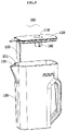
FIG. 5 is a structural schematic view of a water vessel according to a first embodiment of the present invention; -
FIG. 6 is a cross-sectional view of a water vessel according to a first embodiment of the present invention; -
FIG. 7 is a structural schematic view of an automatic water supply device according to a second embodiment of the present invention; -
FIG. 8 is a cross-sectional view of the automatic water supply device according to the second embodiment of the present invention; -
FIG. 9 is an enlarged view of portion B inFIG. 8 ; -
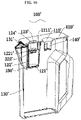
FIG. 10 is a cross-sectional view of a water vessel according to the second embodiment of the present invention. - As shown in
FIG. 1 , the present invention discloses a refrigerator. The refrigerator comprises a cabinet and adoor body 1 for opening and closing the cabinet, an automatic water supply device 2 being provided on an inner side of thedoor body 1. -
FIGS. 2-6 show an automatic water supply device according to a first embodiment of the present disclosure. The automatic water supply device 2 comprises awater vessel 100, abracket 200 for placing thewater vessel 100, detection means 300, and awater supply mechanism 400 for supplying water to thewater vessel 100. The cabinet may define a refrigerating chamber. When thedoor body 1 closes the cabinet, the cold air in the refrigerating chamber may cool the water in thewater vessel 100. - Certainly, sites where the automatic water supply device is used are not limited to refrigerators, and may be various sites such as other refrigeration appliances or cafes. In embodiments of the present invention, water is a collective term of liquid beverages, and includes but not limited to liquid beverages such as purified water, fruit juice, milk or coffee.
- As shown in
FIGS. 2-3 , thewater vessel 100 comprises awater filling port 110. The detection means 300 comprises a switch movably connected to thebracket 200 and asensing unit 320 fitted with the switch. The switch is disposed on thebracket 200 at a position corresponding to a side wall of thewater vessel 100. Thewater supply mechanism 400 comprises awater supply pipe 410 and a water valve provided on thewater supply pipe 410. An outlet of thewater supply pipe 410 corresponds to thewater filling port 110 of thewater vessel 100. The automatic water supply device further comprises a controller. Thesensing unit 320 switches between an ON state and an OFF state based on the movement of the switch. Thewater vessel 100 is placed on thebracket 200 to touch the switch, thereby driving thesensing unit 320 to be in the ON state. Thesensing 320 sends a detection signal characterizing the liquid level in thewater vessel 100 to the controller in the ON state. The controller controls the water valve to open or close according to the detection signal. - The automatic water supply device disclosed in the present invention judges whether the
water vessel 100 is placed on thebracket 200 according to the ON state and OFF state of thesensing unit 320, and then outputs the detection signal characterizing the liquid level in thewater vessel 100 through thesensing unit 320 in the ON state. Onesensing unit 320 may be used to simultaneously detect whether thewater vessel 100 is placed on thebracket 200 as well as the liquid level in thewater vessel 100, thereby controlling the water valve to open when thewater vessel 100 is placed on thebracket 200 and the liquid level is low, to automatically fill water into thewater vessel 100, so that the user may take the cold water conveniently at any time. - Preferably, the sensing unit may be a capacitive sensor, a photoelectric sensor, a pressure/weight sensor, a Hall sensor or the like, and may also be other sensors as long as they may detect and determine the presence of the liquid in the water vessel and/or the liquid level in the water vessel.
- In the embodiment of the present invention, a height nearby the top of the
water vessel 100 is set as a preset liquid level. When the liquid level in the water vessel reaches the preset liquid level, water needn't be further filled and the controller will control the water valve to close; when the liquid level in thewater vessel 100 does not reach the preset liquid level, water needs to be filled into the water vessel, and the controller will control the water valve to open. - Specifically, in the first embodiment of the present invention, the
sensing unit 320 comprises a capacitive sensor which is disposed on thebracket 200 at a position corresponding to the side wall of thewater vessel 100. The capacitive sensor detects the liquid level in thewater vessel 100 in the ON state, and generates the detection signal according to the liquid level. In the embodiment of the present invention, the capacitive sensor is specifically a capacitive liquid level sensor. The capacitive liquid level sensor is a variable medium type capacitor that uses a change of a measured medium surface to cause a capacitance change. Specifically, the switch and the capacitive sensor are disposed on thebracket 300 at a height corresponding to a preset liquid level of thewater vessel 100. When the capacitive sensor is in the ON state, if the liquid level in thewater vessel 100 does not reach the preset liquid level, and the capacitive sensor only detects air, the controller receives the first detection signal and controls the water valve to open. At this time, water will filled into thewater vessel 100; during water filling, the liquid level in thewater vessel 100 gradually rises. When the liquid level is higher than the position of the capacitive sensor, the capacitive sensor can detect that the medium changes from air to water. At this time, the capacitance value changes, and the controller will receive the second detection signal and control the water valve to close so that the automatic water filling is completed. The capacitive sensor has a large detection dynamic range, a fast response speed, a simple structure and a low cost. - In the embodiment of the present invention, the switch comprises a rotating
member 311 rotatably connected to thebracket 200, anelectrical connection member 312 is provided on thebracket 200, and the capacitive sensor is disposed in the rotatingmember 311. When thewater vessel 100 is placed on thevessel 200, the side wall of thewater vessel 100 touches and presses the rotatingmember 311, so that the rotatingmember 311 drives the capacitive sensor to rotate. The capacitive sensor contacts theelectrical connection member 312 to energize the capacitive sensor, so that whether thewater vessel 100 is placed on thebracket 200 may be judged through the ON state and OFF state of the capacitive sensor. Therefore, it is unnecessary to provide an additional sensor, and only the capacitive sensor for detecting the liquid level can be used to detect whether the water vessel is placed on the bracket. In another embodiment, the electrical connection member may be provided on the rotating member, and the capacitive sensor may be fixedly disposed on the bracket. - In another embodiment, the capacitive sensor may also be disposed on the water vessel, and the electrical connection member is disposed on the bracket. When the water vessel is placed on the bracket, the capacitive sensor may be in contact with the electrical connection member to be in an ON state.
- Specifically, the
water supply pipe 410 may be externally connected to the user's water source, and extends along the cabinet of the refrigerator into thedoor body 1. When the water valve is opened, the external water source may fill thewater vessel 100 with water through thewater supply pipe 410. Specifically, in the embodiment of the present invention, the water supply pipe extends from a compressor compartment at a lower part of the cabinet along the cabinet into the inner side of the door body, and the water valve may be provided on the water supply pipe in the compressor compartment. Certainly, in other embodiments, the water valve may also be disposed on other parts of the water supply pipe. - The
electrical connection member 312 is an elastic member. When thewater vessel 100 is placed on thebracket 200, a side wall of thewater vessel 100 presses the rotatingmember 311, and the capacitive sensor contacts theelectrical connection member 312 to make the elasticelectrical connection member 312 in a compressed state. When thewater vessel 100 is removed from thebracket 200, theelectrical connection member 312 may release the elastic force to cause the rotatingmember 311 to rotate reversely, and the capacitive sensor does not contact theelectrical connection member 312 any longer and switches to the OFF state. After thewater vessel 100 is taken from the thebracket 200, the elasticelectrical connection member 312 enables the rotatingmember 311 to be automatically elastically driven to rotate, thereby making the capacitive sensor to switch to the ON state and simplifying the ON/OFF state switching of the capacitive sensor. Theelectrical connection member 312 may preferably be a compression spring. As shown inFIG. 4 , three compression springs extend from thebracket 200, and correspond to the three contacts on the sensor, respectively. - The capacitive sensor comprises at least three contacts. When the rotating
member 311 is pressed, the at least three contacts are all in contact with theelectrical connection member 312. The at least three contacts include at least two electrical connection contacts and at least one signal connection contact. In the embodiment of the present invention, as shown inFIG. 4 , the capacitive sensor comprises three contacts, two of which are electrical connection contacts, and the remaining one is a signal connection contact. Correspondingly, threeelectrical connection members 312 are provided on thebracket 200. When the rotatingmember 311 is pressed, the two electrical connection contacts and one signal connection contact of the capacitive sensor are respectively communicated with the correspondingelectrical connection members 312, so that the capacitive sensor is in the ON state. After the controller detects that the capacitive sensor is in the ON state, it may determine that thewater vessel 100 is already placed on thebracket 200. The signal connection contact is used to send a detection signal characterizing the liquid level in thewater vessel 100 to the controller when the capacitive sensor is in the ON state. - As shown in
FIGS. 5-6 , thewater vessel 100 further comprises awater vessel lid 120, awater vessel body 130, a water storage space defined by thewater vessel lid 120 and thewater vessel body 130, and thewater filling port 110 is disposed on thewater vessel lid 120. Thewater vessel 100 further comprises awater filling cup 140 extending from thewater filling port 110 to the bottom of thewater vessel 100. A plurality ofwater outlets 141 communicated with the water storage space are provided on a peripheral wall of thewater filling cup 140. Thewater filling cup 140 may slow down the flow rate of the water upon water filling, reduce the noise upon water filling, and prevent the water flow from splashing around. - Preferably, the
water filling cup 140 comprises an upwardly-protrudingbottom wall 142, and thewater outlets 141 extend from top to bottom on the peripheral wall to a position connected to thebottom wall 142. Specifically, a plurality ofelongated water outlets 141 are provided at an interval on the peripheral wall of thewater filling cup 140, and thewater outlets 141 extend on the peripheral wall of thewater filling cup 140 so that water can flow into the water storage space quickly without gathering in thewater filling cup 140. The upward protrusion of thebottom wall 142 may further prevent the water in thewater filling cup 140 from gathering and enable the water to flow out through thewater outlets 141. - A
water spout 131 is disposed on thewater vessel body 130, and awater baffle 150 is provided at a position adjacent to thewater spout 131 in the water storage space. Awater passageway 151 communicated with thewater spout 131 is formed between thewater baffle 150 and the inner wall of thewater vessel 100. When the user takes water, he may pour out water through thewater spout 131. Thewater baffle 150 is provided to prevent the water from flowing rapidly and splashing out of thewater vessel 100 when the user pours water. - Preferably, the
water baffle 150 is preferably arc-shaped. Furthermore, the arc top of thewater baffle 150 protrudes toward the side wall of thewater vessel 100 opposite to thewater spout 131. The arc-shapedwater baffle 150 has a good water blocking effect, and its arc top protrudes toward the side wall of thewater vessel 100 opposite to thewater spout 131, so that an effective water passageway is formed between thewater baffle 150 and the side wall of thewater vessel 100, and further enhances the splash-preventing effect. - In the embodiment of the present invention, the
water baffle 150 extends from thewater vessel lid 120 to the bottom of thewater vessel 100, and thewater passageway 151 is formed on both sides and the bottom of thewater baffle 150. Thewater baffle 150 extending to the bottom of thewater vessel 100 may guide water into the water passageway from a lower position of thewater vessel 100, thereby further reducing the flow rate of water when poured. - As shown in
FIG. 1 , thedoor 1 is provided with abottle seat 3, and thebracket 200 is additionally disposed on thebottle seat 3. Thebracket 200 is pre-assembled with thebottle seat 3 through a connecting piece. The connecting piece may be specifically a hook structure to facilitate mounting thebracket 200 to or demounting thebracket 200 from thebottle seat 3. When the user does not need to use the water vessel, he may remove thewater vessel 100 and thebracket 200, and the original position where the bracket is placed may continue to be used as the bottle seat. The outlet of thewater supply pipe 410 is fixed at an upper half of thebracket 100 to align with thewater filling port 110 on thewater vessel lid 120 of thewater vessel 100. Thewater vessel 100 is located below thebottle seat 3 and on a side close to the door handle. The water vessel may be drawn out transversely along the width direction of the door body, so it occupies a small space in the refrigerator without affecting the storage space of the shelves in the refrigerating compartment. -
FIGS. 7-10 show an automatic water supply device according to a second embodiment of the present invention. The second embodiment differs from the first embodiment in that thesensing unit 320" includes a sensor 321' that cooperates with the rotating member 311' and an inductive element 322' that is disposed in thewater vessel 100 and rises and falls with the liquid level. The rotating member 311' is disposed on the bracket 200' at a position corresponding to the top of the water vessel 100'. The sensor 321' switches between an ON state and an OFF state based on the movement of the switch, and the rotating member 311' drives the sensor 321' to be in the ON state. The sensor 321' detects the position of the inductive element 322' in the ON state to output a detection signal characterizing the liquid level in the water vessel 100'. The controller controls the opening or closing of the water valve according to the received detection signal of the sensor 321'. - In the present embodiment, the sensor 321' is disposed in the rotating member 311', and the top of the water vessel 100' is provided with a bump 124'. When the water vessel 100' is placed on the bracket 200', the bump 124' on the top of the water vessel 100' presses the switch to cause the rotating member 311' to drive the sensor 321' to rotate to energize the sensor 321', so that whether the water vessel 100' is placed on the bracket 200' through the ON/OFF state of the sensor 321'. Inside the water vessel 100', an inner box 121' is disposed extending downward from the lid 120', and a peripheral wall of the inner box 121' is provided with a plurality of water holes communicated with the water storage space, so that the water in the water vessel 100' may flow into the inner box 121'. Specifically, a float box 122' is disposed in the inner box 121', and the inductive element 322' is disposed in the float box 122'. Specifically, the inner box 121' is snap-fitted on the water vessel lid 120', and the inner box 121' does not rise or fall with the liquid level, whereas the float box 122' moves up and down inside the inner box 121' as the liquid level changes. With the inner box 121' that does not move along with the liquid level being disposed in the water vessel 100', a movement range and movement direction of the float box 122' can be restricted, and it can be ensured that the magnet can only move within a desired height range and move only in the height direction of the water vessel 100'. The inductive element 322' is fixedly disposed in the float box 122' and moves up and down with the float box 122'. The float box 122' seals the inductive element 322' therein to ensure that the float box can float up and down.
- Specifically, an outer diameter of the float box 122' matches an inner diameter of the inner box 121', so that the float box 122' can only move up and down in the height direction of the inner box 121'. The inner wall of the inner box 121' is further provided with a plurality of guide ribs 1211' which extend from top to bottom and can prevent the float box 122' from getting stuck when it moves up and down. An upper surface of the float box 122' is further provided with a plurality of protrusions 1221', and exhaust holes 123' are provided on the water vessel lid 120' at positions corresponding to the protrusions 1221'. Specifically, after the liquid level in the water vessel 100' rises and the upper surface of the float box 122' contacts the bottom surface of the water vessel lid 120', the float box 122' might not fall down when the liquid level falls due to a siphon effect. With the protrusions 1221' being provided on the upper surface of the float box 122' and the exhaust hole 123' being provided on the water vessel lid 100', a gap is present between the upper surface of the float box 122' and the water vessel lid 100' to avoid occurrence of the siphon effect between the upper surface of the float box 122' and the water vessel lid 100', so that the up-down movement of the float box 122' is smoother.
- In the embodiment of the present invention, the sensor 321' is a Hall switch, and the Hall switch is provided on the bracket 200' at a position corresponding to the top of the water vessel 100'; the inductive element 322' is a magnet. The Hall switch is disposed on the water vessel lid 120', and the approaching of the magnet may be detected. Specifically, the Hall switch is an active electromagnetic conversion device made by an integrated packaging and assembling process based on the principle of the Hall effect. The Hall switch may sense the magnitude of the magnetic flux. When the magnetic flux reaches a preset value, a trigger in the Hall switch flips, and an output level state of the Hall switch is also inverted accordingly, so that the magnetic input signal may be converted into an electrical signal. The magnet in the float box 122' will move up and down with the liquid level, and the magnetic flux detected by the Hall switch will also change accordingly. When the Hall switch is in the ON state, the controller receives the signal and determines that the water vessel 100' has been placed on the bracket 200'. If the liquid level in the water vessel 100' does not reach the preset liquid level, the magnet is far away from the Hall switch and the magnetic flux induced by the Hall switch cannot make the trigger inside the Hall switch flip, and the controller will control the water valve to open and fill the water vessel 100' with water. During the water filling process, the liquid level will rise and drive the float box 122' to move upward, and the magnet will also approach the Hall switch until the magnetic flux induced by the Hall switch also reaches a preset value when the liquid level in the water vessel 100' reaches the preset liquid level. At this time, the trigger inside the Hall switch flips to invert the output level state of the Hall switch, and the controller will control the water valve to close and stop water filling. As such, the Hall switch judges the liquid level in the water vessel 100' by detecting the position of the magnet, and the controller may control the opening and closing of the water valve according to the detection signal sent by the Hall switch, to automatically fill the water vessel 100' with water when needed.
- Other structures such as the cabinet door body and the water supply structure in the second embodiment of the present invention are all the same as those in the first embodiment, and will not be detailed any more here.
- Another embodiment of the present invention further discloses an automatic water supply method. The method comprises the following steps: S1: receiving a signal characterizing that the sensing unit is in an ON state. S2: determining whether a first detection signal characterizing that the liquid level in the water vessel reaches a preset level is received. S3: if YES, turning to step S4; if NO, turning to step S5. S4: controlling the water valve to close. S5: controlling the water valve to open, and meanwhile performing step S3.
- When the water vessel is placed on the bracket, the side wall of the water vessel will press the rotating member to energize the sensing unit to be in the ON state. At this time, the controller will receive the signal indicating that the sensing unit is in the ON state. The sensing unit will detect the liquid level in the water vessel. If the liquid level in the water vessel reaches the preset level, the sensing unit will send the first detection signal to the controller; otherwise, the sensing unit will not send the signal to the controller or sends a second detection signal to the controller. When the controller does not receive the first signal or receives the second detection signal, it will control the water valve to be in an open state, whereupon the water supply pipe will automatically fill the water vessel with water. When the liquid level in the water vessel gradually rises to the preset level, the controller receives the first signal and controls the water valve to close to end the automatic water filling. In this way, one sensor is used to achieve the detection of whether the
water vessel 100 is placed on thebracket 200 and the detection of the liquid level in thewater vessel 100 at the same time, so that thewater vessel 100 may be automatically filled with water, and the user may conveniently take a sufficient amount of cold water at any time. - The automatic water supply device disclosed in the present invention judges whether the water vessel is placed on the bracket according to the ON state and OFF state of the sensing unit, and then detects the liquid level in the water vessel through the sensing unit in the ON state. One sensing unit may be used to simultaneously detect whether the water vessel is placed on the bracket as well as the liquid level in the water vessel, thereby controlling the water valve to open when the water vessel is placed on the bracket and the liquid level is low, to automatically fill water into the water vessel, so that the user may take the cold water conveniently at any time. The cooperation of the elastic electrical connection member and the rotating member may cause whether the water vessel is placed on the bracket to correspond to the switching between the ON state and OFF state of the sensing unit. The water filling cup disposed in the water vessel may slow down the flow rate of the water upon water filling, reduce the noise upon water filling, and prevent the water flow from splashing around. The upward protrusion of the bottom wall of the water filling cup may further prevent the water in the water filling cup from gathering and enable the water to flow out through the water outlets. The water baffle is provided to prevent the water from flowing rapidly and splashing out of the water vessel when the user pours water.
Claims (11)
- An automatic water supply device, wherein the device comprises a water vessel, a bracket for placing the water vessel, detection means, and a water supply mechanism for supplying water to the water vessel, the water vessel comprising a water filling port;the detection means comprises a switch movably connected to the bracket and a sensing unit fitted with the switch;the water supply mechanism comprises a water supply pipe and a water valve provided on the water supply pipe, and an outlet of the water supply pipe corresponds to the water filling port of the water vessel;the automatic water supply device further comprises a controller, the sensing unit switches between an ON state and an OFF state based on the movement of the switch, and the water vessel being placed on the bracket to touch the switch, thereby driving the sensing unit to be in the ON state;the sensing unit outputs a detection signal characterizing the liquid level in the water vessel in the ON state, the controller controlling the water valve to open or close according to the detection signal.
- The automatic water supply device according to claim 1, wherein the sensing unit comprises a capacitive sensor which is disposed on the bracket at a position corresponding to the side wall of the water vessel; the capacitive sensor detects the liquid level in the water vessel in the ON state, and generates the detection signal according to the liquid level.
- The automatic water supply device according to claim 1, wherein the switch comprises a rotating member rotatably connected to the bracket, an electrical connection member is provided on the bracket, and the sensor is provided in the rotating member; when the rotating member is pressed, the sensing unit contacts the electrical connection member.
- The automatic water supply device according to claim 3, wherein the sensing unit comprises at least three contacts; when the rotating member is pressed, all of the at least three contacts are in contact with the electrical connection member; the at least three contacts comprise at least two electrical connection contacts and at least one signal connection contact.
- The automatic water supply device according to claim 3, wherein the electrical connection member is an elastic member.
- The automatic water supply device according to claim 1, wherein the water vessel comprises a water vessel lid, a water vessel body, and a water storage space defined by the water vessel lid and the water vessel body, and the water filling port is disposed on the water vessel lid; the water vessel further comprises a water filling cup extending from the water filling port to the bottom of the water vessel, and a plurality of water outlets communicated with the water storage space are provided on a peripheral wall of the water filling cup.
- The automatic water supply device according to claim 6, wherein the water filling cup comprises an upwardly-protruding bottom wall, and the water outlets extend from top to bottom on the peripheral wall to a position connected to the bottom wall.
- The automatic water supply device according to claim 1, wherein the water vessel comprises a water vessel lid, a water vessel body, and a water storage space defined by the water vessel lid and the water vessel body, a water spout is disposed on the water vessel body, a water baffle is provided at a position adjacent to the water spout in the water storage space, and a water passageway communicated with the water spout is formed between the water baffle and the inner wall of the water vessel.
- The automatic water supply device according to claim 8, wherein the water baffle is arc-shaped.
- The automatic water supply device according to claim 8, wherein the water baffle extends from the water vessel lid to the bottom of the water vessel, and the water passageway is formed on both sides and the bottom of the water baffle.
- A refrigerator, wherein the refrigerator comprises a cabinet and a door body for opening and closing the cabinet, the water supply device according to any of claims 1-10 being disposed on an inner side of the door body.
Applications Claiming Priority (2)
| Application Number | Priority Date | Filing Date | Title |
|---|---|---|---|
| CN202010182438.1A CN113405309B (en) | 2020-03-16 | 2020-03-16 | Water supply device and refrigerator having the same |
| PCT/CN2020/115641 WO2021184709A1 (en) | 2020-03-16 | 2020-09-16 | Automatic water supply apparatus and refrigerator having same |
Publications (3)
| Publication Number | Publication Date |
|---|---|
| EP4123249A1 true EP4123249A1 (en) | 2023-01-25 |
| EP4123249A4 EP4123249A4 (en) | 2023-08-09 |
| EP4123249B1 EP4123249B1 (en) | 2025-06-18 |
Family
ID=77676659
Family Applications (1)
| Application Number | Title | Priority Date | Filing Date |
|---|---|---|---|
| EP20925475.4A Active EP4123249B1 (en) | 2020-03-16 | 2020-09-16 | Automatic water supply device and refrigerator having the same |
Country Status (4)
| Country | Link |
|---|---|
| EP (1) | EP4123249B1 (en) |
| CN (1) | CN113405309B (en) |
| AU (1) | AU2020436860B2 (en) |
| WO (1) | WO2021184709A1 (en) |
Families Citing this family (3)
| Publication number | Priority date | Publication date | Assignee | Title |
|---|---|---|---|---|
| CN115419960B (en) * | 2022-08-15 | 2025-04-11 | 中国电信股份有限公司 | Air conditioning water injection system and air conditioning |
| WO2025001848A1 (en) * | 2023-06-26 | 2025-01-02 | 青岛海尔电冰箱有限公司 | Refrigerator, refrigerator control method, and storage medium |
| CN119679297A (en) * | 2023-09-25 | 2025-03-25 | 青岛海尔电冰箱有限公司 | Control method and device for kettle, kettle, refrigerator, and computer-readable storage medium |
Family Cites Families (18)
| Publication number | Priority date | Publication date | Assignee | Title |
|---|---|---|---|---|
| GB2268680B (en) * | 1991-11-05 | 1994-06-29 | Strix Ltd | Water heating jugs |
| JP3575388B2 (en) * | 1992-11-27 | 2004-10-13 | 井関農機株式会社 | Rice cooker |
| JPH08285430A (en) * | 1995-04-10 | 1996-11-01 | Hoshizaki Electric Co Ltd | Cold water feeder |
| EP1645825B1 (en) * | 2004-10-05 | 2012-11-21 | Whirlpool Corporation | Domestic refrigerator with water dispenser assembly |
| KR100871616B1 (en) * | 2007-07-24 | 2008-12-02 | 주식회사 영원코퍼레이션 | Water supply |
| CN102242974B (en) * | 2011-07-08 | 2013-11-20 | 李启明 | Instant heating type electric water heater and hydraulic start device thereof |
| US9890029B2 (en) * | 2011-12-09 | 2018-02-13 | Electrolux Home Products, Inc. | Refrigerator with automatic liquid dispenser |
| CN105806025B (en) * | 2014-12-31 | 2019-07-02 | 青岛海尔股份有限公司 | Water supply device and refrigerator having the same |
| US10674860B2 (en) * | 2016-07-07 | 2020-06-09 | Haier Us Appliance Solutions, Inc. | Single serve beverage dispenser for a refrigerator appliance |
| CN106766657A (en) * | 2016-12-27 | 2017-05-31 | 青岛海尔股份有限公司 | The refrigerator water path control system and the refrigerator with it of a kind of automatic water-supply |
| KR102674196B1 (en) * | 2017-01-03 | 2024-06-12 | 삼성전자주식회사 | Refrigerator and control method thereof |
| WO2018140680A1 (en) * | 2017-01-30 | 2018-08-02 | Electrolux Home Products, Inc. | Refrigerator with automatic liquid dispenser |
| CN107036380A (en) * | 2017-04-17 | 2017-08-11 | 海信容声(广东)冰箱有限公司 | A kind of refrigerator water storage case assembly and refrigerator |
| CN206499341U (en) * | 2017-07-18 | 2017-09-19 | 厦门越一电子科技有限公司 | A kind of water boiling device for exempting from out pot lid |
| CN207739313U (en) * | 2017-10-20 | 2018-08-17 | 合肥华凌股份有限公司 | Water fetching device |
| CN207636781U (en) * | 2017-12-29 | 2018-07-20 | 楚天科技股份有限公司 | A kind of scarce bottle detection device |
| CN208925892U (en) * | 2018-06-21 | 2019-06-04 | 佛山市顺德区美的电热电器制造有限公司 | Hot-water bottle |
| CN212205301U (en) * | 2020-03-16 | 2020-12-22 | 青岛海尔电冰箱有限公司 | Water supply device and refrigerator with same |
-
2020
- 2020-03-16 CN CN202010182438.1A patent/CN113405309B/en active Active
- 2020-09-16 EP EP20925475.4A patent/EP4123249B1/en active Active
- 2020-09-16 AU AU2020436860A patent/AU2020436860B2/en active Active
- 2020-09-16 WO PCT/CN2020/115641 patent/WO2021184709A1/en not_active Ceased
Also Published As
| Publication number | Publication date |
|---|---|
| CN113405309A (en) | 2021-09-17 |
| AU2020436860B2 (en) | 2023-08-03 |
| WO2021184709A1 (en) | 2021-09-23 |
| EP4123249B1 (en) | 2025-06-18 |
| AU2020436860A1 (en) | 2022-10-13 |
| CN113405309B (en) | 2025-06-10 |
| EP4123249A4 (en) | 2023-08-09 |
Similar Documents
| Publication | Publication Date | Title |
|---|---|---|
| CN212205301U (en) | Water supply device and refrigerator with same | |
| EP4123250B1 (en) | Automatic water supply device, refrigerator having same | |
| AU2020436860B2 (en) | Automatic water supply apparatus and refrigerator having same | |
| CN212205300U (en) | Automatic water supply device and refrigerator with same | |
| EP4123248B1 (en) | Automatic water supply device and refrigerator having the same | |
| US5490547A (en) | System for providing a supply of chilled fluid | |
| US10889484B2 (en) | System and method for sensing a liquid level in an autofill pitcher using vibrations | |
| EP3674637A1 (en) | Refrigerating appliance | |
| US9004115B2 (en) | Method and system for dispensing ice and/or a liquid | |
| US20150197417A1 (en) | Self-filling refrigerator water pitcher | |
| US20180162713A1 (en) | Adjustable Liquid Level Autofill Pitcher For An Appliance | |
| KR20140116092A (en) | Refrigerator with automatic liquid dispenser | |
| EP3939933B1 (en) | Contactless liquid dispensing valve | |
| US11780722B1 (en) | Autofill pitcher overfill shutoff mechanism | |
| CN108444187B (en) | A vacuum fresh-keeping device and a refrigeration and freezing device | |
| AU2022224417A1 (en) | Auto-water shut-off for an external door water dispenser | |
| CN214494033U (en) | Intelligent liquid discharge device | |
| CA2562454C (en) | Refrigeration apparatus for cooling pressurized beverages | |
| CN224140606U (en) | Automatic beverage filling machine capable of stopping when full of cup | |
| CN204535255U (en) | Water supply installation and there is the refrigerator of this water supply installation | |
| CN222504542U (en) | A refrigerator | |
| CN222504541U (en) | A refrigerator | |
| CN223489542U (en) | Water drinking equipment | |
| EP4733693A1 (en) | Refrigeration appliance | |
| HK40065689A (en) | Contactless liquid dispensing valve |
Legal Events
| Date | Code | Title | Description |
|---|---|---|---|
| STAA | Information on the status of an ep patent application or granted ep patent |
Free format text: STATUS: THE INTERNATIONAL PUBLICATION HAS BEEN MADE |
|
| PUAI | Public reference made under article 153(3) epc to a published international application that has entered the european phase |
Free format text: ORIGINAL CODE: 0009012 |
|
| STAA | Information on the status of an ep patent application or granted ep patent |
Free format text: STATUS: REQUEST FOR EXAMINATION WAS MADE |
|
| 17P | Request for examination filed |
Effective date: 20220331 |
|
| AK | Designated contracting states |
Kind code of ref document: A1 Designated state(s): AL AT BE BG CH CY CZ DE DK EE ES FI FR GB GR HR HU IE IS IT LI LT LU LV MC MK MT NL NO PL PT RO RS SE SI SK SM TR |
|
| DAV | Request for validation of the european patent (deleted) | ||
| DAX | Request for extension of the european patent (deleted) | ||
| A4 | Supplementary search report drawn up and despatched |
Effective date: 20230711 |
|
| RIC1 | Information provided on ipc code assigned before grant |
Ipc: B67D 1/00 20060101ALI20230705BHEP Ipc: F25D 29/00 20060101ALI20230705BHEP Ipc: F25D 23/12 20060101AFI20230705BHEP |
|
| GRAP | Despatch of communication of intention to grant a patent |
Free format text: ORIGINAL CODE: EPIDOSNIGR1 |
|
| STAA | Information on the status of an ep patent application or granted ep patent |
Free format text: STATUS: GRANT OF PATENT IS INTENDED |
|
| INTG | Intention to grant announced |
Effective date: 20241204 |
|
| GRAS | Grant fee paid |
Free format text: ORIGINAL CODE: EPIDOSNIGR3 |
|
| RAP3 | Party data changed (applicant data changed or rights of an application transferred) |
Owner name: HAIER SMART HOME CO., LTD. Owner name: QINGDAO HAIER REFRIGERATOR CO., LTD |
|
| GRAA | (expected) grant |
Free format text: ORIGINAL CODE: 0009210 |
|
| STAA | Information on the status of an ep patent application or granted ep patent |
Free format text: STATUS: THE PATENT HAS BEEN GRANTED |
|
| AK | Designated contracting states |
Kind code of ref document: B1 Designated state(s): AL AT BE BG CH CY CZ DE DK EE ES FI FR GB GR HR HU IE IS IT LI LT LU LV MC MK MT NL NO PL PT RO RS SE SI SK SM TR |
|
| REG | Reference to a national code |
Ref country code: GB Ref legal event code: FG4D |
|
| REG | Reference to a national code |
Ref country code: CH Ref legal event code: EP |
|
| REG | Reference to a national code |
Ref country code: DE Ref legal event code: R096 Ref document number: 602020053114 Country of ref document: DE |
|
| REG | Reference to a national code |
Ref country code: CH Ref legal event code: EP |
|
| REG | Reference to a national code |
Ref country code: IE Ref legal event code: FG4D |
|
| PG25 | Lapsed in a contracting state [announced via postgrant information from national office to epo] |
Ref country code: FI Free format text: LAPSE BECAUSE OF FAILURE TO SUBMIT A TRANSLATION OF THE DESCRIPTION OR TO PAY THE FEE WITHIN THE PRESCRIBED TIME-LIMIT Effective date: 20250618 |
|
| PGFP | Annual fee paid to national office [announced via postgrant information from national office to epo] |
Ref country code: DE Payment date: 20250916 Year of fee payment: 6 |
|
| REG | Reference to a national code |
Ref country code: LT Ref legal event code: MG9D |
|
| PG25 | Lapsed in a contracting state [announced via postgrant information from national office to epo] |
Ref country code: NO Free format text: LAPSE BECAUSE OF FAILURE TO SUBMIT A TRANSLATION OF THE DESCRIPTION OR TO PAY THE FEE WITHIN THE PRESCRIBED TIME-LIMIT Effective date: 20250918 Ref country code: GR Free format text: LAPSE BECAUSE OF FAILURE TO SUBMIT A TRANSLATION OF THE DESCRIPTION OR TO PAY THE FEE WITHIN THE PRESCRIBED TIME-LIMIT Effective date: 20250919 |
|
| PG25 | Lapsed in a contracting state [announced via postgrant information from national office to epo] |
Ref country code: BG Free format text: LAPSE BECAUSE OF FAILURE TO SUBMIT A TRANSLATION OF THE DESCRIPTION OR TO PAY THE FEE WITHIN THE PRESCRIBED TIME-LIMIT Effective date: 20250618 |
|
| PGFP | Annual fee paid to national office [announced via postgrant information from national office to epo] |
Ref country code: GB Payment date: 20250919 Year of fee payment: 6 |
|
| PG25 | Lapsed in a contracting state [announced via postgrant information from national office to epo] |
Ref country code: HR Free format text: LAPSE BECAUSE OF FAILURE TO SUBMIT A TRANSLATION OF THE DESCRIPTION OR TO PAY THE FEE WITHIN THE PRESCRIBED TIME-LIMIT Effective date: 20250618 |
|
| PGFP | Annual fee paid to national office [announced via postgrant information from national office to epo] |
Ref country code: FR Payment date: 20250929 Year of fee payment: 6 |
|
| PG25 | Lapsed in a contracting state [announced via postgrant information from national office to epo] |
Ref country code: RS Free format text: LAPSE BECAUSE OF FAILURE TO SUBMIT A TRANSLATION OF THE DESCRIPTION OR TO PAY THE FEE WITHIN THE PRESCRIBED TIME-LIMIT Effective date: 20250918 |
|
| REG | Reference to a national code |
Ref country code: NL Ref legal event code: MP Effective date: 20250618 |
|
| PG25 | Lapsed in a contracting state [announced via postgrant information from national office to epo] |
Ref country code: LV Free format text: LAPSE BECAUSE OF FAILURE TO SUBMIT A TRANSLATION OF THE DESCRIPTION OR TO PAY THE FEE WITHIN THE PRESCRIBED TIME-LIMIT Effective date: 20250618 |
|
| PG25 | Lapsed in a contracting state [announced via postgrant information from national office to epo] |
Ref country code: NL Free format text: LAPSE BECAUSE OF FAILURE TO SUBMIT A TRANSLATION OF THE DESCRIPTION OR TO PAY THE FEE WITHIN THE PRESCRIBED TIME-LIMIT Effective date: 20250618 |
|
| PG25 | Lapsed in a contracting state [announced via postgrant information from national office to epo] |
Ref country code: PT Free format text: LAPSE BECAUSE OF FAILURE TO SUBMIT A TRANSLATION OF THE DESCRIPTION OR TO PAY THE FEE WITHIN THE PRESCRIBED TIME-LIMIT Effective date: 20251020 |
|
| REG | Reference to a national code |
Ref country code: AT Ref legal event code: MK05 Ref document number: 1804507 Country of ref document: AT Kind code of ref document: T Effective date: 20250618 |
|
| PG25 | Lapsed in a contracting state [announced via postgrant information from national office to epo] |
Ref country code: IS Free format text: LAPSE BECAUSE OF FAILURE TO SUBMIT A TRANSLATION OF THE DESCRIPTION OR TO PAY THE FEE WITHIN THE PRESCRIBED TIME-LIMIT Effective date: 20251018 |
|
| PG25 | Lapsed in a contracting state [announced via postgrant information from national office to epo] |
Ref country code: SM Free format text: LAPSE BECAUSE OF FAILURE TO SUBMIT A TRANSLATION OF THE DESCRIPTION OR TO PAY THE FEE WITHIN THE PRESCRIBED TIME-LIMIT Effective date: 20250618 Ref country code: AT Free format text: LAPSE BECAUSE OF FAILURE TO SUBMIT A TRANSLATION OF THE DESCRIPTION OR TO PAY THE FEE WITHIN THE PRESCRIBED TIME-LIMIT Effective date: 20250618 |
|
| PG25 | Lapsed in a contracting state [announced via postgrant information from national office to epo] |
Ref country code: CZ Free format text: LAPSE BECAUSE OF FAILURE TO SUBMIT A TRANSLATION OF THE DESCRIPTION OR TO PAY THE FEE WITHIN THE PRESCRIBED TIME-LIMIT Effective date: 20250618 |
|
| PG25 | Lapsed in a contracting state [announced via postgrant information from national office to epo] |
Ref country code: PL Free format text: LAPSE BECAUSE OF FAILURE TO SUBMIT A TRANSLATION OF THE DESCRIPTION OR TO PAY THE FEE WITHIN THE PRESCRIBED TIME-LIMIT Effective date: 20250618 |
|
| PG25 | Lapsed in a contracting state [announced via postgrant information from national office to epo] |
Ref country code: EE Free format text: LAPSE BECAUSE OF FAILURE TO SUBMIT A TRANSLATION OF THE DESCRIPTION OR TO PAY THE FEE WITHIN THE PRESCRIBED TIME-LIMIT Effective date: 20250618 |
|
| PG25 | Lapsed in a contracting state [announced via postgrant information from national office to epo] |
Ref country code: SK Free format text: LAPSE BECAUSE OF FAILURE TO SUBMIT A TRANSLATION OF THE DESCRIPTION OR TO PAY THE FEE WITHIN THE PRESCRIBED TIME-LIMIT Effective date: 20250618 |
|
| PG25 | Lapsed in a contracting state [announced via postgrant information from national office to epo] |
Ref country code: ES Free format text: LAPSE BECAUSE OF FAILURE TO SUBMIT A TRANSLATION OF THE DESCRIPTION OR TO PAY THE FEE WITHIN THE PRESCRIBED TIME-LIMIT Effective date: 20250618 |
|
| PG25 | Lapsed in a contracting state [announced via postgrant information from national office to epo] |
Ref country code: RO Free format text: LAPSE BECAUSE OF FAILURE TO SUBMIT A TRANSLATION OF THE DESCRIPTION OR TO PAY THE FEE WITHIN THE PRESCRIBED TIME-LIMIT Effective date: 20250618 |
|
| PG25 | Lapsed in a contracting state [announced via postgrant information from national office to epo] |
Ref country code: DK Free format text: LAPSE BECAUSE OF FAILURE TO SUBMIT A TRANSLATION OF THE DESCRIPTION OR TO PAY THE FEE WITHIN THE PRESCRIBED TIME-LIMIT Effective date: 20250618 |
|
| PG25 | Lapsed in a contracting state [announced via postgrant information from national office to epo] |
Ref country code: IT Free format text: LAPSE BECAUSE OF FAILURE TO SUBMIT A TRANSLATION OF THE DESCRIPTION OR TO PAY THE FEE WITHIN THE PRESCRIBED TIME-LIMIT Effective date: 20250618 |
|
| PLBE | No opposition filed within time limit |
Free format text: ORIGINAL CODE: 0009261 |
|
| STAA | Information on the status of an ep patent application or granted ep patent |
Free format text: STATUS: NO OPPOSITION FILED WITHIN TIME LIMIT |
|
| REG | Reference to a national code |
Ref country code: CH Ref legal event code: L10 Free format text: ST27 STATUS EVENT CODE: U-0-0-L10-L00 (AS PROVIDED BY THE NATIONAL OFFICE) Effective date: 20260430 |