EP4123195A1 - Damper device - Google Patents
Damper device Download PDFInfo
- Publication number
- EP4123195A1 EP4123195A1 EP22177914.3A EP22177914A EP4123195A1 EP 4123195 A1 EP4123195 A1 EP 4123195A1 EP 22177914 A EP22177914 A EP 22177914A EP 4123195 A1 EP4123195 A1 EP 4123195A1
- Authority
- EP
- European Patent Office
- Prior art keywords
- sliding
- plate
- damper device
- rotary body
- control plate
- Prior art date
- Legal status (The legal status is an assumption and is not a legal conclusion. Google has not performed a legal analysis and makes no representation as to the accuracy of the status listed.)
- Granted
Links
Images













Classifications
-
- F—MECHANICAL ENGINEERING; LIGHTING; HEATING; WEAPONS; BLASTING
- F16—ENGINEERING ELEMENTS AND UNITS; GENERAL MEASURES FOR PRODUCING AND MAINTAINING EFFECTIVE FUNCTIONING OF MACHINES OR INSTALLATIONS; THERMAL INSULATION IN GENERAL
- F16F—SPRINGS; SHOCK-ABSORBERS; MEANS FOR DAMPING VIBRATION
- F16F15/00—Suppression of vibrations in systems; Means or arrangements for avoiding or reducing out-of-balance forces, e.g. due to motion
- F16F15/10—Suppression of vibrations in rotating systems by making use of members moving with the system
- F16F15/12—Suppression of vibrations in rotating systems by making use of members moving with the system using elastic members or friction-damping members, e.g. between a rotating shaft and a gyratory mass mounted thereon
- F16F15/121—Suppression of vibrations in rotating systems by making use of members moving with the system using elastic members or friction-damping members, e.g. between a rotating shaft and a gyratory mass mounted thereon using springs as elastic members, e.g. metallic springs
- F16F15/123—Wound springs
- F16F15/1232—Wound springs characterised by the spring mounting
-
- F—MECHANICAL ENGINEERING; LIGHTING; HEATING; WEAPONS; BLASTING
- F16—ENGINEERING ELEMENTS AND UNITS; GENERAL MEASURES FOR PRODUCING AND MAINTAINING EFFECTIVE FUNCTIONING OF MACHINES OR INSTALLATIONS; THERMAL INSULATION IN GENERAL
- F16F—SPRINGS; SHOCK-ABSORBERS; MEANS FOR DAMPING VIBRATION
- F16F15/00—Suppression of vibrations in systems; Means or arrangements for avoiding or reducing out-of-balance forces, e.g. due to motion
- F16F15/10—Suppression of vibrations in rotating systems by making use of members moving with the system
- F16F15/12—Suppression of vibrations in rotating systems by making use of members moving with the system using elastic members or friction-damping members, e.g. between a rotating shaft and a gyratory mass mounted thereon
- F16F15/129—Suppression of vibrations in rotating systems by making use of members moving with the system using elastic members or friction-damping members, e.g. between a rotating shaft and a gyratory mass mounted thereon characterised by friction-damping means
-
- F—MECHANICAL ENGINEERING; LIGHTING; HEATING; WEAPONS; BLASTING
- F16—ENGINEERING ELEMENTS AND UNITS; GENERAL MEASURES FOR PRODUCING AND MAINTAINING EFFECTIVE FUNCTIONING OF MACHINES OR INSTALLATIONS; THERMAL INSULATION IN GENERAL
- F16D—COUPLINGS FOR TRANSMITTING ROTATION; CLUTCHES; BRAKES
- F16D3/00—Yielding couplings, i.e. with means permitting movement between the connected parts during the drive
- F16D3/02—Yielding couplings, i.e. with means permitting movement between the connected parts during the drive adapted to specific functions
- F16D3/12—Yielding couplings, i.e. with means permitting movement between the connected parts during the drive adapted to specific functions specially adapted for accumulation of energy to absorb shocks or vibration
-
- F—MECHANICAL ENGINEERING; LIGHTING; HEATING; WEAPONS; BLASTING
- F16—ENGINEERING ELEMENTS AND UNITS; GENERAL MEASURES FOR PRODUCING AND MAINTAINING EFFECTIVE FUNCTIONING OF MACHINES OR INSTALLATIONS; THERMAL INSULATION IN GENERAL
- F16D—COUPLINGS FOR TRANSMITTING ROTATION; CLUTCHES; BRAKES
- F16D7/00—Slip couplings, e.g. slipping on overload, for absorbing shock
- F16D7/02—Slip couplings, e.g. slipping on overload, for absorbing shock of the friction type
- F16D7/024—Slip couplings, e.g. slipping on overload, for absorbing shock of the friction type with axially applied torque limiting friction surfaces
- F16D7/025—Slip couplings, e.g. slipping on overload, for absorbing shock of the friction type with axially applied torque limiting friction surfaces with flat clutching surfaces, e.g. discs
-
- F—MECHANICAL ENGINEERING; LIGHTING; HEATING; WEAPONS; BLASTING
- F16—ENGINEERING ELEMENTS AND UNITS; GENERAL MEASURES FOR PRODUCING AND MAINTAINING EFFECTIVE FUNCTIONING OF MACHINES OR INSTALLATIONS; THERMAL INSULATION IN GENERAL
- F16F—SPRINGS; SHOCK-ABSORBERS; MEANS FOR DAMPING VIBRATION
- F16F15/00—Suppression of vibrations in systems; Means or arrangements for avoiding or reducing out-of-balance forces, e.g. due to motion
- F16F15/10—Suppression of vibrations in rotating systems by making use of members moving with the system
- F16F15/12—Suppression of vibrations in rotating systems by making use of members moving with the system using elastic members or friction-damping members, e.g. between a rotating shaft and a gyratory mass mounted thereon
- F16F15/121—Suppression of vibrations in rotating systems by making use of members moving with the system using elastic members or friction-damping members, e.g. between a rotating shaft and a gyratory mass mounted thereon using springs as elastic members, e.g. metallic springs
- F16F15/1215—Leaf springs, e.g. radially extending
-
- F—MECHANICAL ENGINEERING; LIGHTING; HEATING; WEAPONS; BLASTING
- F16—ENGINEERING ELEMENTS AND UNITS; GENERAL MEASURES FOR PRODUCING AND MAINTAINING EFFECTIVE FUNCTIONING OF MACHINES OR INSTALLATIONS; THERMAL INSULATION IN GENERAL
- F16F—SPRINGS; SHOCK-ABSORBERS; MEANS FOR DAMPING VIBRATION
- F16F15/00—Suppression of vibrations in systems; Means or arrangements for avoiding or reducing out-of-balance forces, e.g. due to motion
- F16F15/10—Suppression of vibrations in rotating systems by making use of members moving with the system
- F16F15/12—Suppression of vibrations in rotating systems by making use of members moving with the system using elastic members or friction-damping members, e.g. between a rotating shaft and a gyratory mass mounted thereon
- F16F15/121—Suppression of vibrations in rotating systems by making use of members moving with the system using elastic members or friction-damping members, e.g. between a rotating shaft and a gyratory mass mounted thereon using springs as elastic members, e.g. metallic springs
- F16F15/123—Wound springs
- F16F15/12353—Combinations of dampers, e.g. with multiple plates, multiple spring sets, i.e. complex configurations
-
- F—MECHANICAL ENGINEERING; LIGHTING; HEATING; WEAPONS; BLASTING
- F16—ENGINEERING ELEMENTS AND UNITS; GENERAL MEASURES FOR PRODUCING AND MAINTAINING EFFECTIVE FUNCTIONING OF MACHINES OR INSTALLATIONS; THERMAL INSULATION IN GENERAL
- F16F—SPRINGS; SHOCK-ABSORBERS; MEANS FOR DAMPING VIBRATION
- F16F15/00—Suppression of vibrations in systems; Means or arrangements for avoiding or reducing out-of-balance forces, e.g. due to motion
- F16F15/30—Flywheels
-
- F—MECHANICAL ENGINEERING; LIGHTING; HEATING; WEAPONS; BLASTING
- F16—ENGINEERING ELEMENTS AND UNITS; GENERAL MEASURES FOR PRODUCING AND MAINTAINING EFFECTIVE FUNCTIONING OF MACHINES OR INSTALLATIONS; THERMAL INSULATION IN GENERAL
- F16F—SPRINGS; SHOCK-ABSORBERS; MEANS FOR DAMPING VIBRATION
- F16F2222/00—Special physical effects, e.g. nature of damping effects
- F16F2222/04—Friction
-
- F—MECHANICAL ENGINEERING; LIGHTING; HEATING; WEAPONS; BLASTING
- F16—ENGINEERING ELEMENTS AND UNITS; GENERAL MEASURES FOR PRODUCING AND MAINTAINING EFFECTIVE FUNCTIONING OF MACHINES OR INSTALLATIONS; THERMAL INSULATION IN GENERAL
- F16F—SPRINGS; SHOCK-ABSORBERS; MEANS FOR DAMPING VIBRATION
- F16F2232/00—Nature of movement
- F16F2232/02—Rotary
Definitions
- JP 2021 - 101 389 A filed on June 18, 2021 including the specification, drawings and abstract is incorporated herein by reference in its entirety.
- the technology disclosed herein relates to a damper device.
- a damper device is provided in a torque transfer path between a drive source such as an engine and a transmission to absorb vibration of torque transferred from the drive source to the transmission.
- the damper device is incorporated in a clutch device, for example.
- a damper device with a common configuration is known to include a coil spring interposed between a disk plate as an input member and a hub as an output member, which are rotatable relative to each other, to absorb and damp torque fluctuations using elastic deformation of the coil spring. It is also known to further absorb the torque fluctuations by generating sliding torque (hysteresis torque) based on relative rotation between the disk plate and the hub, in addition to using the elastic deformation of the coil spring.
- JP 6 471 486 B discloses a damper device that includes, as main constituent elements, a first rotary member (reference sign 1 in JP 6 471 486 B ) provided on the input side of power transfer, a second rotary member (reference sign 2 in JP 6 471 486 B ) provided on the output side of power transfer, two control plates (reference signs 31 and 32 in JP 6 471 486 B ), a first sliding member (reference signs 6 and 7 in JP 6 471 486 B ) that generates first sliding torque, a second sliding member (reference signs 8 and 9 in JP 6 471 486 B ) that generates second sliding torque that is larger than the first sliding torque, an elastic member 57 for which a cone spring is used, etc.
- a first rotary member reference sign 1 in JP 6 471 486 B
- second rotary member reference sign 2 in JP 6 471 486 B
- two control plates reference signs 31 and 32 in JP 6 471 486 B
- a first sliding member
- a damper device with a short axial length is provided through various embodiments.
- a damper device that can stably generate a variety of hysteresis torques is also provided.
- a first aspect provides a damper device including: a first rotary body that includes at least a first plate that is rotatable about a rotational axis and a second plate that is disposed to face the first plate and that is rotatable about the rotational axis together with the first plate; a second rotary body that is rotatable relative to the first rotary body about the rotational axis; an elastic mechanism portion that elastically couples the first rotary body and the second rotary body to each other in a rotational direction; a control plate that includes a radially extending portion that extends in a radial direction to abut against the elastic mechanism portion and an axially extending portion that extends in an axial direction to be at least partially housed in one of the first rotary body and the second rotary body, the control plate being disposed in only one of a first housing space between the first plate and the second rotary body and a second housing space between the second plate and the second rotary body in the axial direction; a first sliding portion that is
- one of the first sliding torque and the second sliding torque may be larger than the other, and may be generated only when the first rotary body and the second rotary body are rotated relative to each other in a predetermined direction.
- the damper device can generate small hysteresis torque (the smaller one of the first sliding torque and the second sliding torque) at all times when the first rotary body and the second rotary body are rotated relative to each other, and generate large hysteresis torque (the larger one of the first sliding torque and the second sliding torque) in the special case where the first rotary body and the second rotary body are rotated relative to each other in the predetermined direction.
- the magnitude of the "large hysteresis torque" can be further increased by setting one of the first sliding torque and the second sliding torque that is generated only in the special case to be larger than the other.
- the damper device can generate a variety of hysteresis torques.
- the "large hysteresis torque" discussed above can be used to suppress relatively large vibration or noise generated when an engine of a vehicle (hybrid vehicle, in particular) is started, for example.
- the elastic mechanism portion may include a first elastic member and a pair of seat members that supports the first elastic member by holding the first elastic member between the seat members from both sides, and the radially extending portion may abut against the first elastic member or one of the pair of seat members.
- the radially extending portion can reliably abut against the elastic mechanism portion.
- the damper device according to the third aspect can efficiently generate the first sliding torque and the second sliding torque.
- the first sliding portion may include a first sliding surface that is slid with respect to the first rotary body or the radially extending portion and a second elastic member that biases the first sliding surface in a direction of moving closer to the first rotary body or the radially extending portion.
- the damper device can generate the first sliding torque reliably and efficiently.
- the second sliding portion may include a second sliding surface that is slid with respect to the second rotary body or the radially extending portion and a third elastic member that biases the second sliding surface in a direction of moving closer to the second rotary body or the radially extending portion.
- the damper device can generate the second sliding torque reliably and efficiently.
- the first sliding portion and the second sliding portion may be formed integrally with the control plate to function as a part of the control plate; and the radially extending portion may be directly slid with respect to the first rotary body, and directly slid with respect to the second rotary body.
- the sixth aspect it is possible to further reduce the number of components of the damper device according to the sixth aspect by constituting the control plate, the first sliding portion, and the second sliding portion as an integral object.
- a thrust member that includes at least one of a first surface that is slid with respect to the first rotary body and a second surface that is slid with respect to the second rotary body may be further provided in one of the first housing space and the second housing space that is different from one of the first housing space and the second housing space in which the control plate is disposed.
- the damper device can further generate additional hysteresis torque based on the first surface and the second surface.
- the thrust member may include a fourth elastic member that biases the second surface in a direction of moving closer to the second rotary body.
- the damper device can generate the additional hysteresis torque discussed above reliably and efficiently.
- a damper device with a short axial length can be provided through the various embodiments.
- a damper device that can stably generate a variety of hysteresis torques can also be provided.
- FIG. 1 is a schematic top view schematically illustrating the configuration of a damper device 1 according to the first embodiment.
- FIG. 2 is a schematic top view schematically illustrating the configuration of the damper device 1 illustrated in FIG. 1 from which some constituent elements have been omitted.
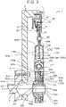
- FIG. 3 is a schematic sectional view schematically illustrating the configuration of the damper device 1 illustrated in FIG. 1 taken along the line X-X.
- FIG. 4 is a schematic perspective view illustrating the configuration of the damper device 1 according to the first embodiment as exploded into constituent elements.
- FIG. 1 is a schematic top view schematically illustrating the configuration of a damper device 1 according to the first embodiment.
- FIG. 5 is a schematic perspective view illustrating a control plate 300 of the damper device 1 according to the first embodiment as enlarged.
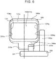
- FIG. 6 is a schematic view schematically illustrating only a region of the damper device 1 according to the first embodiment surrounded by the dotted line in FIG. 2 as enlarged. It should be noted that a pair of seat members 420 of an elastic mechanism portion 400 to be discussed later is not illustrated in FIG. 6 for convenience, and that the relationship of abutment between constituent elements (e.g. between the elastic mechanism portion 400 and a disk plate 100 and between the elastic mechanism portion 400 and a hub 200) is not illustrated accurately.
- the damper device 1 is provided in a power transfer path between a drive source (not illustrated) such as an engine or a motor and a transmission etc., and receives power from the drive source via a flywheel 2 and transfers (outputs) the power to the transmission etc. (see FIG. 3 ).
- a drive source such as an engine or a motor and a transmission etc.
- the damper device 1 absorbs and damps torque vibration.
- the damper device 1 mainly includes a disk plate 100 as a first rotary body to which power is transferred from the flywheel 2, a hub 200 as a second rotary body, a control plate 300, an elastic mechanism portion 400, a thrust member 500, a first sliding portion 600, and a second sliding portion 700.
- the axial direction means a direction that extends in parallel with a rotational axis O
- the radial direction means a direction that is orthogonal to the rotational axis O
- the circumferential direction means a direction that circulates around the rotational axis O.
- the flywheel 2 is an annular plate member fixed by a bolt 3 to a drive shaft Z connected to the drive source.
- power transferred from the drive shaft Z to the flywheel 2 is transferred to the disk plate 100 via a cover plate 10 fixed to the flywheel 2 by a bolt 4 to rotate together with the flywheel 2 and a first friction material 20.
- a pressure plate 30 is fixed to the cover plate 10.
- the cover plate 10 and the pressure plate 30 are configured to rotate together with each other.
- a support plate 11 is fixed to the flywheel 2 together with the cover plate 10 by the bolt 4.
- the support plate 11 supports a disk spring 40.
- the disk spring 40 biases the pressure plate 30 so as to be pressed against a lining plate 101 of the disk plate 100, to be discussed later, via a second friction material 21, and transfers the power transferred to the flywheel 2 to the disk plate 100 (lining plate 101) together with the cover plate 10.
- the support plate 11, the pressure plate 30, and the disk spring 40 can function as a limiter that causes slipping (blocks power transfer from the cover plate 10 and the pressure plate 30 to the disk plate 100) when the damper device 1 cannot absorb torque fluctuations in the torsional direction.
- the limiter may be combined with a structure known in the art.
- the disk plate 100 is formed from a metal material, for example, and provided so as to be rotatable about the rotational axis O with the hub 200 as the second rotary body, to be discussed later, etc. interposed as illustrated in FIGS. 1 to 4 .
- the disk plate 100 includes a first plate 100A and a second plate 100B as a pair of substantially disk-shaped plate members provided on both sides of the hub 200 in the axial direction (with the second plate 100B disposed to face the first plate 100A in the axial direction). As illustrated in FIGS.
- the first plate 100A and the second plate 100B are shaped to be symmetrical to each other in the axial direction, and coupled to each other by a plurality of rivets 120 provided in the vicinity of the outer periphery thereof with the substantially annular lining plate 101, which can appropriately adjust the positions of the two plates in the axial direction, interposed therebetween so as to be rotatable together with each other.
- the first plate 100A and the second plate 100B cooperate with each other to have an axially swelling shape so as to form housing regions (four housing regions are illustrated in the example illustrated in FIG. 1 ) that house the elastic mechanism portion 400, to be discussed later, in correlation with regions I to IV as illustrated in FIGS. 1 and 2 .
- Each of the housing regions extends substantially linearly or substantially arcuately along the circumferential direction of the disk plate 100 in order to house a first elastic member 410 of the elastic mechanism portion 400 that extends along the circumferential direction of the disk plate 100 and a pair of seat members 420 (a seat member 420A and a seat member 420B).
- the regions I to IV refer to the four regions each having a fan shape of approximately 90 degrees, as illustrated in FIG. 1 , when the damper device 1 is seen from above.
- the first plate 100A and the second plate 100B form a first housing region 102a, a second housing region 102b, a third housing region 102c, and a fourth housing region 102d that extend along the circumferential direction in correlation with the regions I to IV, respectively.
- the hub 200 is provided with window holes 206a, 206b, 206c, and 206d corresponding to the first housing region 102a, the second housing region 102b, the third housing region 102c, and the fourth housing region 102d, respectively.
- the first plate 100A and the second plate 100B include one end surface (fourth one end surface) 104d 1 and the other end surface (fourth other end surface) 104d 2 that faces the one end surface 104d 1 as side walls that surround the fourth housing region 102d.
- the fourth one end surface 104d 1 and the fourth other end surface 104d 2 extend along the axial direction of the disk plate 100, by way of example.
- the first plate 100A and the second plate 100B include one end surface (first one end surface) 104a 1 and the other end surface (first other end surface) 104a 2 that faces the one end surface 104a 1 as side walls that surround the first housing region 102a.
- the first plate 100A and the second plate 100B include one end surface (second one end surface) 104b 1 and the other end surface (second other end surface) 104b 2 that faces the one end surface 104b 1 as side walls that surround the second housing region 102b.
- the first plate 100A and the second plate 100B include one end surface (third one end surface) 104c 1 and the other end surface (third other end surface) 104c 2 that faces the one end surface 104c 1 as side walls that surround the third housing region 102c.
- the side walls abut against (are engaged with) the elastic mechanism portion 400 to be discussed later.
- the lining plate 101 of the disk plate 100 is disposed at the same axial position (on the same line in the radial direction) as the hub 200.
- a notch 105 that allows movement (relative rotation) of the hub 200 in the circumferential direction is provided in each of the regions I to IV of the lining plate 101.
- the outer edge portion of the notch 105 functions as a regulating portion 106 that regulates excessive relative rotation of the hub 200.
- An inner surface 110A of the first plate 100A can support a second elastic member 604 that may form a part of the first sliding portion 600 to be discussed later. As discussed later, when the first sliding portion 600 is provided between the second plate 100B and the hub 200, an inner surface 110B of the second plate 100B can support the second elastic member 604.
- first plate 100A and the second plate 100B will be discussed later as appropriate.
- the hub 200 as the second rotary body functions as an output member of the damper device 1, is formed from a metal material, for example, has a substantially disk-like shape as a whole, and is provided as interposed between the first plate 100A and the second plate 100B so as to be rotatable relative to the disk plate 100 (the first plate 100A and the second plate 100B) about the rotational axis O.
- the hub 200 has a through hole 203 formed in a cylindrical portion 202 that is substantially cylindrical.
- An input shaft (not illustrated) of the transmission can be inserted through the through hole 203 to be splined with the hub 200.
- the hub 200 is provided with a disk portion 205 that extends radially outward from the cylindrical portion 202.
- the disk portion 205 is provided with the window holes 206a, 206b, 206c, and 206d corresponding to the first housing region 102a, the second housing region 102b, the third housing region 102c, and the fourth housing region 102d, respectively, and provided at equal intervals.
- the window holes 206a to 206d provided in the hub 200 are each provided in correspondence with the elastic mechanism portion 400 to be discussed later. That is, the elastic mechanism portion 400 is housed in each of the window holes 206a to 206d.
- the window hole 206a which is provided in correlation with the region I, has a one-end engagement portion (first one-end engagement portion) 206a 1 and an other-end engagement portion (first other-end engagement portion) 206a 2 that faces the one-end engagement portion 206a 1 , and abuts against (is engaged with) the elastic mechanism portion 400.
- the window hole 206b which is provided in correlation with the region II, has a one-end engagement portion (second one-end engagement portion) 206bi and an other-end engagement portion (second other-end engagement portion) 206b 2 that faces the one-end engagement portion 206bi, and abuts against (is engaged with) the elastic mechanism portion 400.
- the window hole 206c which is provided in correlation with the region III, has a one-end engagement portion (third one-end engagement portion) 206c 1 and an other-end engagement portion (third other-end engagement portion) 206c 2 that faces the one-end engagement portion 206c 1 , and abuts against (is engaged with) the elastic mechanism portion 400.
- the window hole 206d which is provided in correlation with the region IV, has a one-end engagement portion (fourth one-end engagement portion) 206d 1 and an other-end engagement portion (fourth other-end engagement portion) 206d 2 that faces the one-end engagement portion 206di, and abuts against (is engaged with) the elastic mechanism portion 400.
- Each of the window holes 206a to 206d "abutting against the elastic mechanism portion 400" means that each of the window holes 206a to 206d abuts against the first elastic member 410 or the pair of seat members 420 to be discussed later.
- Protruding portions 207a, 207b, 207c, and 207d are provided at the radial end portion of the disk portion 205 in correlation with the regions I to IV, respectively.
- the protruding portions 207a to 207d are each housed in the notch 105 provided in the lining plate 101 such that the hub 200 is rotatable relative to the disk plate 100.
- the protruding portions 207a to 207d each abut against the regulating portion 106, which is the outer edge portion of the notch 105, to regulate excessive relative rotation of the hub 200.
- groove portions 208a, 208b, 208c, and 208d that receive axially extending portions 303a to 303d of the control plate 300, to be discussed later, are provided on the radially inner side of the window holes 206a, 206b, 206c, and 206d, respectively, discussed above. While the groove portions 208a to 208d are provided continuously (integrally) with the window holes 206a to 206d, respectively, in the damper device 1 according to the first embodiment, this is not limiting. The groove portions 208a to 208d may be provided in any portion of the disk portion 205.
- Control Plate 300
- the control plate 300 is formed from a metal material such as spring steel, for example, and has a substantially annular shape as a whole.
- the damper device 1 according to the embodiment is provided with only one control plate 300.
- the control plate 300 is disposed in only one of a first housing space 100x, which is provided between the first plate 100A and the hub 200, and a second housing space 100y, which is provided between the second plate 100B and the hub 200, in the axial direction. In the example illustrated in FIG. 3 , the control plate 300 is disposed in the first housing space 100x.
- the control plate 300 mainly includes a main portion 301 provided in a substantially annular shape, a radially extending portion 302 that extends in the radial direction from the main portion 301 to abut against the elastic mechanism portion 400 to be discussed later, and an axially extending portion 303 that extends in the axial direction to be at least partially housed in the hub 200 (a case where the axially extending portion 303 is partially housed in the first rotary body 100 will be discussed later).
- the radially extending portion 302 includes a radially extending portion 302a in the region I, a radially extending portion 302b in the region II, a radially extending portion 302c in the region III, and a radially extending portion 302d in the region IV, provided in correspondence with the regions I to IV, respectively, discussed above.
- the axially extending portion 303 includes an axially extending portion 303a in the region I, an axially extending portion 303b in the region II, an axially extending portion 303c in the region III, and an axially extending portion 303d in the region IV, provided in correspondence with the regions I to IV, respectively, discussed above.
- the radially extending portions 302a to 302d are provided in correlation with the regions I to IV, respectively.
- the radially extending portion 302a is provided so as to abut against the first elastic member 410 (or one of the seat member 420A and the seat member 420B that constitute the pair of seat members 420) housed in the first housing region 102a (window hole 206a).
- the radially extending portion 302b is provided so as to abut against the first elastic member 410 (or one of the seat member 420A and the seat member 420B that constitute the pair of seat members 420) housed in the second housing region 102b (window hole 206b).
- the radially extending portion 302c is provided so as to abut against the first elastic member 410 (or one of the seat member 420A and the seat member 420B that constitute the pair of seat members 420) housed in the third housing region 102c (window hole 206c).
- the radially extending portion 302d is provided so as to abut against the first elastic member 410 (or one of the seat member 420A and the seat member 420B that constitute the pair of seat members 420) housed in the fourth housing region 102d (window hole 206d).
- the length over which the radially extending portions 302a to 302d extend in the radial direction is not specifically limited as long as a sufficient contact area can be secured for contact with the elastic mechanism portion 400 (the first elastic member 410 or one of the seat member 420A and the seat member 420B that constitute the pair of seat members 420).
- the radially extending portions 302a to 302d face both the first plate 100A and the hub 200 in the axial direction.
- the radially extending portions 302a to 302d have a surface that is in sliding contact with the first sliding portion 600, to be discussed later, disposed between the first plate 100A and the control plate 300 to generate first sliding torque.
- the axially extending portions 303a to 303d are provided in correlation with the regions I to IV, respectively.
- the axially extending portion 303a is housed in the groove portion 208a provided on the radially inner side of the window hole 206a.
- the axially extending portion 303b is housed in the groove portion 208b provided on the radially inner side of the window hole 206b.
- the axially extending portion 303c is housed in the groove portion 208c provided on the radially inner side of the window hole 206c.
- the axially extending portion 303d is housed in the groove portion 208d provided on the radially inner side of the window hole 206d.
- the axially extending portion 303a is housed at a position proximate to a wall portion 208w that defines the groove portion 208a (a position at least off the center position of the groove portion 208a).
- the axially extending portion 303b, the axially extending portion 303c, and the axially extending portion 303d are also housed at a similar position to the axially extending portion 303a in the corresponding groove portions 208b, 208c, and 208d, respectively.
- the axially extending portions 303a to 303d are not engaged or fitted by any mechanism with the hub 200 in the corresponding groove portions 208a to 208d, respectively, and the hub 200 and the control plate 300 are configured to be rotatable together with each other only in a predetermined case. Thus, the control plate 300 and the hub 200 are not rotated together with each other at all times.
- the hub 200 When the hub 200 is rotated in a predetermined direction (e.g. L direction (counterclockwise direction) in FIGS. 1 and 2 ) relative to the disk plate 100 by a predetermined torsion angle or more, for example, the axially extending portions 303a to 303d each abut against the wall portion 208w that defines the groove portions 208a to 208d, respectively. Consequently, the control plate 300 is rotated in the predetermined direction (e.g. L direction (counterclockwise direction) in FIGS. 1 and 2 ) relative to the disk plate 100 together with the hub 200 only when the hub 200 is rotated in the predetermined direction (L direction in FIGS.
- a predetermined direction e.g. L direction (counterclockwise direction) in FIGS. 1 and 2
- the radially extending portion 302a can be in sliding contact with a sliding surface (first sliding surface) 602a of the first sliding portion 600, to be discussed later, to generate first sliding torque.
- the radially extending portions 302b to 302d can also be in sliding contact with the first sliding surface 602a of the first sliding portion 600 to generate first sliding torque.
- the mechanism that allows the control plate 300 and the hub 200 to rotate together with each other will also be discussed in detail later.
- the hub 200 is basically rotated relative to the control plate 300.
- the second sliding portion 700 to be discussed later, disposed between the hub 200 and the control plate 300 can be slid with respect to the hub 200, or slid with respect to the control plate 300, to generate second sliding torque.
- a commonly known friction material is applied separately, or a predetermined surface treatment is applied, to surfaces of the radially extending portions 302a to 302d that are in sliding contact with the first sliding surface 602a of the first sliding portion 600, in order to increase (or decrease) the magnitude of the first sliding torque. Consequently, it is possible to adjust the magnitude of the first sliding torque to a desired magnitude.
- a commonly known friction material is applied separately, or a predetermined surface treatment is applied, to surfaces of the radially extending portions 302a to 302d that are in sliding contact with the second sliding portion 700 (surfaces on the opposite side in the axial direction of the surfaces that are in sliding contact with the first sliding surface 602a of the first sliding portion 600), in order to increase (or decrease) the magnitude of the second sliding torque.
- the first sliding torque generated only in the "predetermined case” discussed above is set, as appropriate, so as to be larger than the second sliding torque using the friction material, surface treatment, etc. discussed above.
- the elastic mechanism portion 400 is mainly constituted from the first elastic member 410 and the pair of seat members 420 (the seat member 420A and the seat member 420B) that supports the first elastic member 410 by holding the first elastic member 410 therebetween from both sides in each of the regions I to IV as illustrated in FIGS. 1 to 4 and 6
- the pair of seat members 420 may be omitted. While one first elastic member 410 may be disposed in each of the regions I to IV as illustrated in FIGS. 1 to 4 , two or more first elastic members 410 may be disposed in series with each other.
- a common coil spring can be used as the first elastic member 410, by way of example.
- the form, structure, etc. of the seat member 420A and the seat member 420B are not specifically limited as long as the seat members 420A and 420B may support the first elastic member 410 as interposed therebetween from both sides.
- seat members known in the art can be used.
- FIGS. 1 to 4 by way of example, four housing regions, namely the first housing region 102a, the second housing region 102b, the third housing region 102c, and the fourth housing region 102d (in correspondence with which the hub 200 is provided with the window holes 206a, 206b, 206c, and 206d, respectively, as discussed above), are formed in the disk plate 100.
- one first elastic member 410 and a pair of seat members 420 are housed in each of the four housing regions, that is, in correlation with each of the regions I to IV
- the seat member 420A is engaged with each of the first one end surface 104a 1 of the disk plate 100 (the first plate 100A and the second plate 100B) and the first one-end engagement portion 206a 1 provided on the hub 200.
- the seat member 420B is engaged with each of the first other end surface 104a 2 of the disk plate 100 (the first plate 100A and the second plate 100B) and the first other-end engagement portion 206a 2 provided on the hub 200.
- the seat member 420A and the seat member 420B that constitute the pair of seat members 420 are engaged with the disk plate 100 and the hub 200.
- the radially extending portions 302a to 302d of the control plate 300 are provided so as to abut against the first elastic member 410 (or one of the seat member 420A and the seat member 420B that constitute the pair of seat members 420) in the regions I to IV, respectively, as illustrated in FIGS. 2 , etc.
- the elastic mechanism portion 400 can elastically couple the disk plate 100 and the hub 200 to each other in the rotational direction. That is, when power from a drive source such as an engine or a motor is transferred in the order of the disk plate 100, the elastic mechanism portion 400, and the hub 200 and the disk plate 100 and the hub 200 are rotated relative to each other, the first elastic member 410 of the elastic mechanism portion 400 is compressed and deformed to absorb torque fluctuations.
- a drive source such as an engine or a motor
- the thrust member 500 is disposed in one of the first housing space 100x and the second housing space 100y discussed above that is different from the space in which the control plate 300 is disposed. That is, in the first embodiment illustrated in FIGS. 1 to 6 , the control plate 300 is disposed in the first housing space 100x, and therefore the thrust member 500 is disposed in the second housing space 100y, rather than the first housing space 100x. When the control plate 300 is disposed in the second housing space 100y, the thrust member 500 is disposed in the first housing space 100x.
- the thrust member 500 is disposed between the second plate 100B and the hub 200 as illustrated in FIG. 3 .
- the thrust member 500 is formed from a resin material, for example, and includes a substantially cylindrical fitting portion 501 and a main portion 502 that has a substantially annular shape as a whole.
- the fitting portion 501 corresponds to a fitting hole 112 provided in the second plate 100B, and may be fitted (engaged) in the fitting hole 112, by way of example. Consequently, the thrust member 500 is integrated with the second plate 100B (disk plate 100), and rotated together with the disk plate 100 about the rotational axis O.
- the fitting portion 501 may be fitted in a different fitting hole (not illustrated) provided separately in the hub 200, for example, rather than being fitted in the fitting hole 112 provided in the second plate 100B, to be rotated together with the hub 200 about the rotational axis O.
- the fitting portion 501 may be configured not to be fitted with any of the second plate 100B and the hub 200.
- the main portion 502 includes a first surface 502x that is slidable with respect to the second plate 100B and a second surface 502y that is slidable with respect to the hub 200. Consequently, the main portion 502 can generate sliding torque (third sliding torque) that is different from the first sliding torque and the second sliding torque discussed above, by sliding with respect to the second plate 100B and/or the hub 200.
- the second elastic member 604 of the first sliding portion 600 biases a plate portion 602 in the direction of moving closer to the control plate 300 (in the leftward direction on the drawing sheet of FIG. 3 ).
- a reaction force related to the biasing is transferred from the second elastic member 604 to the first plate 100A so that the first plate 100A is slightly biased in the direction of moving away from the control plate 300 (in the rightward direction on the drawing sheet of FIG. 3 ).
- the second plate 100B integrated with the first plate 100A via the rivets 120 is also slightly biased in the direction of moving closer to the control plate 300 (in the rightward direction on the drawing sheet of FIG. 3 ). Consequently, the second surface 502y of the thrust member 500 is pressed against the hub 200 to generate the third sliding torque discussed above.
- the third sliding torque is generated at all times when the disk plate 100 and the hub 200 are rotated relative to each other, and can be used both when "small hysteresis torque" is constituted and when "large hysteresis torque is constituted” in the damper device 1.
- the "small hysteresis torque” means the resultant torque of the second sliding torque discussed above and the third sliding torque
- the "large hysteresis torque” means the resultant torque of the first sliding torque discussed above and the third sliding torque.
- the first sliding portion 600 is disposed between the disk plate 100 (first plate 100A) and the control plate 300, and is slid with respect to the radially extending portion 302 (radially extending portions 302a to 302d) of the control plate 300 to generate first sliding torque.
- the first sliding portion 600 includes a substantially annular plate portion 602 that includes a first sliding surface 602a that is slid with respect to the radially extending portion 302 (radially extending portions 302a to 302d) of the control plate 300, and a second elastic member 604 that biases the first sliding surface 602a of the plate portion 602 in the direction of moving closer to the radially extending portion 302 of the control plate 300 (in the leftward direction on the drawing sheet of FIG. 3 ).
- the first sliding portion 600 is configured such that the plate portion 602 extends in the axial direction to be engaged with the first plate 100A with the second elastic member 604 supported by the first plate 100A.
- the first sliding portion 600 is configured to be rotatable together with the disk plate 100. Consequently, the first sliding portion 600 can generate first sliding torque with the first sliding surface 602a pressed against the radially extending portion 302 when the control plate 300 is rotated relative to the disk plate 100.
- the plate portion 602 is formed from a resin material, a metal material constituted from a compound containing 3d transition metal, etc., for example.
- a commonly known friction material is applied separately, or a predetermined surface treatment is applied, to the first sliding surface 602a, in order to increase (or decrease) the magnitude of the first sliding torque generated through the sliding with respect to the radially extending portion 302. Consequently, it is possible to adjust the magnitude of the first sliding torque to a desired magnitude.
- the second elastic member 604 biases the first sliding surface 602a of the plate portion 602 in the direction of moving closer to the radially extending portion 302 of the control plate 300 (in the leftward direction on the drawing sheet of FIG. 3 ), as discussed above, while being supported by the first plate 100A.
- a reaction force related to the biasing is transferred from the second elastic member 604 to the first plate 100A.
- the second sliding portion 700 is disposed between the control plate 300 and the hub 200, and is slid with respect to at least the hub 200 to generate second sliding torque.
- the second sliding portion 700 has a substantially annular shape as a whole, and includes a second sliding surface 702a that is slidable with respect to the hub 200.
- the second sliding portion 700 is rotated relative to the hub 200, and the second sliding surface 702a is slid with respect to the hub 200 to generate second sliding torque.
- the control plate 300 is biased in the direction of moving closer to the hub 200 in conjunction with the plate portion 602 of the first sliding portion 600 being biased in the direction of moving closer to the control plate 300 by the second elastic member 604 of the first sliding portion 600 discussed above.
- the biased control plate 300 biases the second sliding portion 700 in the direction of moving closer to the hub 200. Consequently, the second sliding surface 702a of the second sliding portion 700 is pressed against the hub 200 to reliably generate second sliding torque. That is, the biasing force of the second elastic member 604 is transferred sequentially to the plate portion 602, the control plate 300, and the second sliding portion 700.
- the second sliding portion 700 may include a second sliding surface 702b that may be slid with respect to the control plate 300 to generate second sliding torque.
- the second sliding surface 702b and the radially extending portion 302 of the control plate 300 can be slid with respect to each other to generate second sliding torque.
- the second sliding portion 700 may be configured to be engaged with the control plate 300 to rotate together with the control plate 300, may be configured to be engaged with neither of the control plate 300 and the hub 200, or may be configured to be engaged with the first plate 100A, for example.
- a commonly known friction material is applied separately, or a predetermined surface treatment is applied, to the second sliding surfaces 702a and 702b, as with the other sliding surfaces.
- FIG. 7A is a schematic top view schematically illustrating a state in which the first rotary body (disk plate 100) and the second rotary body (hub 200) are not rotated relative to each other in the damper device 1 according to the first embodiment.
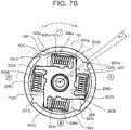
- FIG. 7B is a schematic top view schematically illustrating a state in which the second rotary body (hub 200) is rotated to the positive side relative to the first rotary body (disk plate 100) by a torsion angle of ⁇ 1° in the damper device 1 according to the first embodiment.
- FIG. 7A is a schematic top view schematically illustrating a state in which the first rotary body (disk plate 100) and the second rotary body (hub 200) are not rotated relative to each other in the damper device 1 according to the first embodiment.
- FIG. 7B is a schematic top view schematically illustrating a state in which the second rotary body (hub 200) is rotated to the positive side relative to the first rotary body (disk plate 100) by a torsion angle of
- FIG. 7C is a schematic top view schematically illustrating a state in which the second rotary body (hub 200) is rotated to the positive side relative to the first rotary body (disk plate 100) by a torsion angle of ⁇ 2° in the damper device 1 according to the first embodiment.
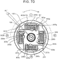
- FIG. 7D is a schematic top view schematically illustrating a state in which the second rotary body (hub 200) is rotated to the negative side relative to the first rotary body (disk plate 100) by a torsion angle of ⁇ 3° in the damper device 1 according to the first embodiment.
- FIG. 7C is a schematic top view schematically illustrating a state in which the second rotary body (hub 200) is rotated to the positive side relative to the first rotary body (disk plate 100) by a torsion angle of ⁇ 2° in the damper device 1 according to the first embodiment.
- FIG. 7D is a schematic top view schematically illustrating a state in which the second rotary body (hub 200) is rotated to
- FIG. 7E is a schematic top view schematically illustrating a state in which the second rotary body (hub 200) is rotated to the negative side relative to the first rotary body (disk plate 100) by a torsion angle of ⁇ 4° in the damper device 1 according to the first embodiment.
- FIG. 7F is a schematic top view schematically illustrating a state in which rotation of the second rotary body (hub 200) relative to the first rotary body (disk plate 100) is being resolved from the state in FIG. 7E in the damper device 1 according to the first embodiment.
- FIG. 8 is a schematic characteristic chart schematically illustrating the torsional characteristics of the damper device 1 according to the first embodiment.
- the pair of seat members 420 the seat member 420A and the seat member 420B of the elastic mechanism portion 400 is not illustrated for convenience.
- FIG. 7A illustrates a state in which power from the drive source such as an engine or a motor is transferred to the damper device 1 but in which no relative rotation is caused between the disk plate 100 and the hub 200 (torsion angle: 0°). In this case, none of the first sliding torque, the second sliding torque, and the third sliding torque discussed above is generated.
- the axially extending portions 303a to 303d of the control plate 300 are housed in the corresponding groove portions 208a to 208d of the hub 200 at a position proximate to the wall portion 208w that defines the groove portions 208a to 208d, respectively.
- a gap with the same size is formed between the axially extending portion 303a and the wall portion 208w, between the axially extending portion 303b and the wall portion 208w, between the axially extending portion 303c and the wall portion 208w, and between the axially extending portion 303d and the wall portion 208w, and each of the axially extending portions 303a to 303d does not abut against the wall portion 208w.
- FIG. 7B illustrates a state in which relative rotation is caused between the disk plate 100 and the hub 200 from the state in FIG. 7A to cause torsion of ⁇ 1° to the positive side.
- the positive side refers to the case where the hub 200 is rotated (moved) in the R direction (clockwise direction in FIG. 7B ) relative to the disk plate 100, for example. In this case, the hub 200 is rotated relative to the disk plate 100 while distorting the first elastic members 410.
- the size of the gap between each of the axially extending portions 303a to 303d and the corresponding wall portion 208w is gradually increased, and therefore the two (the axially extending portion 303 and the wall portion 208w) still do not abut against each other.
- the control plate 300 is not affected by the rotation of the hub 200 relative to the disk plate 100, and is not rotated relative to the disk plate 100.
- the control plate 300 is rotated relative to the hub 200 (the hub 200 is rotated relative to the control plate 300).
- the third sliding torque discussed above is generated through the sliding between the second surface 502y of the thrust member 500 rotated together with the disk plate 100 and the hub 200 (disk portion 205).
- the second sliding torque is generated with the second sliding surface 702a of the second sliding portion 700 slid with respect to the hub 200 (disk portion 205) based on the relative rotation between the hub 200 and the control plate 300.
- the second sliding torque discussed above may be generated through the sliding between the sliding surface 702b of the second sliding portion 700 and the radially extending portion 302 (radially extending portions 302a to 302d) of the control plate 300.
- the resultant torque of the third sliding torque and the second sliding torque is generated as hysteresis torque, and the hysteresis torque in this case corresponds to "small hysteresis torque".
- FIG. 7C illustrates a state in which the rotation of the hub 200 relative to the disk plate 100 is further increased from the state in FIG. 7B to cause torsion of ⁇ 2° to the positive side.
- the hub 200 is rotated relative to the disk plate 100 while further distorting the first elastic members 410.
- each of the protruding portions 207a to 207d of the hub 200 abuts against the regulating portion 106 provided on the lining plate 101. Consequently, relative rotation of the hub 200 to the positive side by more than ⁇ 2° is regulated, and therefore the torsion angle of ⁇ 2° can be grasped as the maximum torsion angle to the positive side.
- the size of the gap between each of the axially extending portions 303a to 303d and the corresponding wall portion 208w is further increased, and therefore the two still do not abut against each other.
- the control plate 300 is not affected by the rotation of the hub 200 relative to the disk plate 100, and is not rotated relative to the disk plate 100.
- the control plate 300 is rotated relative to the hub 200 (the hub 200 is rotated relative to the control plate 300).
- FIG. 7D illustrates a state in which relative rotation is caused between the disk plate 100 and the hub 200 from the state in FIG. 7A to cause torsion of ⁇ 3° to the negative side.
- the negative side refers to the case where the hub 200 is rotated (moved) in the L direction (counterclockwise direction in FIG. 7D ) relative to the disk plate 100, for example. In this case, the hub 200 is rotated relative to the disk plate 100 while distorting the first elastic members 410.
- the size of the gap between each of the axially extending portions 303a to 303d and the corresponding wall portion 208w is gradually reduced, and the two abut against each other (the gap is eliminated) at a torsion angle of ⁇ 3°.
- the control plate 300 is not affected by the rotation of the hub 200 relative to the disk plate 100, and still is not rotated relative to the disk plate 100.
- the control plate 300 is rotated relative to the hub 200 (the hub 200 is rotated relative to the control plate 300).
- Each of the radially extending portions 302a to 302d of the control plate 300 basically abuts against the elastic mechanism portion 400 in each of the regions I to IV.
- each of the radially extending portions 302a to 302d abuts against the elastic mechanism portion 400 at all times when the hub 200 is not rotated relative to the disk plate 100 (state in FIG. 7A ) and when the hub 200 is rotated relative to the disk plate 100 to the positive side (states in FIGS. 7B and 7C ).
- the torsion angle is varied from 0° to ⁇ 3°, however, the relationship of abutment is sequentially resolved.
- a gap is formed between each of the radially extending portions 302a to 302d of the control plate 300 and the first elastic member 410 (elastic mechanism portion 400), and the size of the gap is sequentially increased. This is made in conjunction with the gap between each of the axially extending portions 303a to 303d and the wall portion 208w being eliminated as discussed above.
- FIG. 7E illustrates a state in which the rotation of the hub 200 relative to the disk plate 100 is further increased from the state in FIG. 7D to cause torsion of ⁇ 4° to the negative side.
- the hub 200 is rotated relative to the disk plate 100 while further distorting the first elastic members 410.
- each of the protruding portions 207a to 207d of the hub 200 abuts against the regulating portion 106 provided on the lining plate 101. Consequently, relative rotation of the hub 200 to the negative side by more than ⁇ 4° is regulated, and therefore the torsion angle of ⁇ 4° can be grasped as the maximum torsion angle to the negative side.
- the gap formed in the state in FIG. 7D is still formed between each of the radially extending portions 302a to 302d of the control plate 300 and the elastic mechanism portion 400 (first elastic member 410).
- each of the axially extending portions 303a to 303d and the corresponding wall portion 208w abut against each other.
- the control plate 300 axially extending portions 303a to 303d
- the hub 200 integralally with the hub 200
- the hub 200 as guided by the hub 200 (wall portion 208w).
- the disk plate 100 and the hub 200 are rotated relative to each other, and therefore the third sliding torque discussed above is generated, as when a transition is made from the state in FIG. 7A to the state in FIG. 7B .
- the control plate 300 is also rotated relative to the disk plate 100, and therefore the first sliding torque discussed above is generated between the first sliding surface 602a of the first sliding portion 600 and the radially extending portion 302 (radially extending portions 302a to 302d) of the control plate 300 as discussed above.
- the hub 200 and the control plate 300 are rotated together with each other, and therefore the second sliding torque is not generated.
- the first sliding torque generated in this case is set in advance to be larger than the second sliding torque.
- Such setting is made by adjusting, as appropriate, the friction coefficients of the first sliding surface 602a and the radially extending portions 302a to 302d that generate the first sliding torque by any method discussed above.
- the resultant torque of the third sliding torque and the first sliding torque is generated as hysteresis torque, and the hysteresis torque in this case corresponds to "large hysteresis torque".
- FIG. 7F illustrates a state in which the rotation of the hub 200 relative to the disk plate 100 is being resolved from the state in FIG. 7E , in the middle of a transition from a maximum torsion angle of ⁇ 4° to a torsion angle of 0° on the negative side.
- the hub 200 is relatively moved in the R direction toward a torsion angle of 0° while gradually resolving the torsion of the first elastic member 410. That is, the torsion angle in the state in FIG. 7F can be considered to be a torsion angle between ⁇ 3° and ⁇ 4°, for example.
- the predetermined angle is defined as ⁇ °, for example
- the gap formed in the state in FIG. 7D (and FIG. 7E ) between each of the radially extending portions 302a to 302d of the control plate 300 and the elastic mechanism portion 400 is gradually reduced to be finally eliminated. Consequently, each of the radially extending portions 302a to 302d of the control plate 300 and the elastic mechanism portion 400 abut against each other again.
- the elastic mechanism portion 400 is still distorted, and therefore the elastic mechanism portion 400 presses (biases) the control plate 300 in the R direction. Consequently, the control plate 300 is now rotated in the R direction relative to the disk plate 100 based on a biasing force due to the distortion of the elastic mechanism portion 400.
- the torsional characteristics of the damper device 1 are as indicated in FIG. 8 .
- the "large hysteresis torque" generated on only the negative side as discussed above, that is, hysteresis torque obtained by adding the first sliding torque and the third sliding torque, is suitably used to absorb torque fluctuations caused when an engine of a hybrid vehicle is started under any condition in a state in which the vehicle is driven by only a motor with the engine stationary, for example.
- the "small hysteresis torque" that is, hysteresis torque obtained by adding the second sliding torque and the third sliding torque, can be generated.
- the damper device 1 according to the first embodiment can render the axial length of the damper device 1 short by using a single control plate 300, generate relatively small hysteresis torque on the positive side and relatively large hysteresis torque on the negative side, and stably generate a variety of hysteresis torques.
- the damper device 1 according to the first embodiment generates first sliding torque on the radially extending portion 302 of the control plate 300 via the first sliding portion 600.
- the damper device 1 can be designed relatively easily from the viewpoint of the shape, structure, strength, etc. of the control plate 300.
- FIG. 9 is a schematic sectional view schematically illustrating the configuration of the damper device 1 according to the second embodiment.
- FIG. 9 indicates in a simple manner that the damper device 1 according to the second embodiment has the following configuration that is different from that of the damper device 1 according to the first embodiment, focusing on the region I.
- FIG. 9 While some constituent elements that are common to the damper device 1 according to the first embodiment illustrated in FIGS. 3 etc. and the damper device 1 according to the second embodiment illustrated in FIG. 9 are expressed slightly differently in FIG. 9 for convenience, it should be understood that the shape etc. of the constituent elements according to the two embodiments are common unless specifically described otherwise, except for the following different configuration.
- the configuration of the damper device 1 according to the second embodiment is generally the same as that of the damper device 1 according to the first embodiment discussed above, the configuration of the thrust member 500 and the first sliding portion 600 is different from that according to the first embodiment discussed above. Components of the damper device 1 according to the second embodiment that are the same as those of the damper device 1 according to the first embodiment will not be described in detail.
- the thrust member 500 of the damper device 1 according to the second embodiment further includes, in addition to an integral component constituted from the substantially cylindrical fitting portion 501 and the substantially annular main portion 502 discussed above, a fourth elastic member 505 that biases the integral component in the direction of moving closer to the hub 200 (in the rightward direction on the drawing sheet of FIG. 9 ). While a commonly known disk spring can be used as the fourth elastic member 505, this is not limiting.
- the first sliding portion 600 of the damper device 1 according to the second embodiment does not include the second elastic member 604 which is a constituent element in the first embodiment, and is composed of only the plate portion 602.
- the second surface 502y of the thrust member 500 is pressed against the hub 200 (disk portion 205) by the biasing force of the fourth elastic member 505. Consequently, it is possible to generate the third sliding torque discussed above reliably and efficiently when the disk plate 100 and the hub 200 are rotated relative to each other.
- the fourth elastic member 505 biases the second surface 502y in the direction of moving closer to the hub 200
- a reaction force related to the biasing is transferred from the fourth elastic member 505 to the second plate 100B in conjunction with the biasing.
- the second plate 100B is slightly biased in the direction of moving away from the hub 200 (in the leftward direction on the drawing sheet of FIG. 9 ).
- the first plate 100A integrated with the second plate 100B via the rivets 120 is also slightly biased in the direction of moving closer to the control plate 300 (in the leftward direction on the drawing sheet of FIG. 9 ).
- the biasing force transferred to the first plate 100A may be replaced with the biasing force applied by the second elastic member 604 according to the first embodiment.
- first sliding portion 600 of the damper device 1 it is possible to generate first sliding torque between the first sliding surface 602a of the first sliding portion 600 and the radially extending portion 302 of the control plate 300, even if the second elastic member 604 which is a constituent element in the first embodiment is omitted.
- FIG. 10 is a schematic sectional view schematically illustrating the configuration of the damper device 1 according to the third embodiment.
- FIG. 10 indicates in a simple manner that the damper device 1 according to the third embodiment has the following configuration that is different from that of the damper device 1 according to the first embodiment, focusing on the region I.
- FIG. 10 While some constituent elements that are common to the damper device 1 according to the first embodiment illustrated in FIGS. 3 etc. and the damper device 1 according to the third embodiment illustrated in FIG. 10 are expressed slightly differently in FIG. 10 for convenience, it should be understood that the shape etc. of the constituent elements according to the two embodiments are common unless specifically described otherwise, except for the following different configuration.
- the configuration of the damper device 1 according to the third embodiment is generally the same as that of the damper device 1 according to the first embodiment discussed above, the configuration of the first sliding portion 600 and the second sliding portion 700 is different from that according to the first embodiment discussed above. Components of the damper device 1 according to the third embodiment that are the same as those of the damper device 1 according to the first embodiment will not be described in detail.
- the second sliding portion 700 of the damper device 1 according to the third embodiment further includes, in addition to an integral component that includes the second sliding surface 702a (and 702b) in a substantially annular shape, a third elastic member 705 that biases the integral component in the direction of moving closer to the hub 200 (in the leftward direction on the drawing sheet of FIG. 10 ). While a commonly known disk spring can be used as the third elastic member 705, this is not limiting.
- the first sliding portion 600 of the damper device 1 according to the third embodiment does not include the second elastic member 604 which is a constituent element in the first embodiment, and is composed of only the plate portion 602.
- the second sliding surface 702a of the second sliding portion 700 is pressed against the hub 200 (disk portion 205) by the biasing force of the third elastic member 705. Consequently, it is possible to generate the second sliding torque discussed above reliably and efficiently when the disk plate 100 and the hub 200 are rotated relative to each other and the hub 200 is rotated relative to the control plate 300 (the control plate 300 is rotated relative to the hub 200).
- the control plate 300 is slightly biased in the direction of moving closer to the first plate 100A (in the rightward direction on the drawing sheet of FIG. 10 ). Consequently, it is possible to generate first sliding torque reliably and efficiently with the radially extending portion 302 of the control plate 300 pressed against the first sliding surface 602a of the first sliding portion 600 in the damper device 1 according to the third embodiment. In this configuration, the control plate 300 is biased in the direction of moving closer to the first plate 100A.
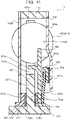
- FIG. 11 is a schematic sectional view schematically illustrating the configuration of the damper device 1 according to the fourth embodiment.
- FIG. 11 indicates in a simple manner that the damper device 1 according to the fourth embodiment has the following configuration that is different from that of the damper device 1 according to the first embodiment, focusing on the region I.
- FIG. 11 While some constituent elements that are common to the damper device 1 according to the first embodiment illustrated in FIGS. 3 etc. and the damper device 1 according to the fourth embodiment illustrated in FIG. 11 are expressed slightly differently in FIG. 11 for convenience, it should be understood that the shape etc. of the constituent elements according to the two embodiments are basically common, except for the following different configuration.
- the configuration of the damper device 1 according to the fourth embodiment is generally the same as that of the damper device 1 according to the first embodiment discussed above, the configuration of the first sliding portion 600 is different from that according to the first embodiment discussed above. Components of the damper device 1 according to the fourth embodiment that are the same as those of the damper device 1 according to the first embodiment will not be described in detail.
- first sliding portion 600 of the damper device 1 according to the fourth embodiment is similar to that according to the first embodiment in being composed of the plate portion 602 and a second elastic member 604x (the second elastic member 604 in the first embodiment), the second elastic member 604x biases the plate portion 602 in the direction of moving closer to the first plate 100A (in the rightward direction on the drawing sheet of FIG. 11 ), rather than in the direction of moving closer to the control plate 300 (in the leftward direction on the drawing sheet of FIG. 11 ).
- the first sliding portion 600 of the damper device 1 according to the fourth embodiment is configured to be engaged with the control plate 300 (the plate portion 602 is engaged with the radially extending portion 302 of the control plate 300, for example), unlike the first embodiment. Thus, the first sliding portion 600 can be rotated together with the control plate 300.
- the second elastic member 604x may be the same as the second elastic member 604 according to the first embodiment.
- the first sliding surface 602a of the first sliding portion 600 is pressed against the inner surface 110A of the first plate 100A when the control plate 300 and the disk plate 100 are rotated relative to each other (i.e. in the "predetermined case” discussed above).
- first sliding torque reliably and efficiently between the first sliding surface 602a and the inner surface 110A of the first plate 100A.
- a surface of the plate portion 602 that faces the control plate 300 is referred to as the "first sliding surface 602a".
- the fourth embodiment as illustrated in FIG.
- first sliding surface 602a a surface of the plate portion 602 that faces the first plate 100A.
- first sliding surface 602a is a surface of the first sliding portion 600 that generates first sliding torque.
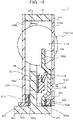
- FIG. 12 is a schematic sectional view schematically illustrating the configuration of the damper device 1 according to the fifth embodiment.
- FIG. 12 indicates in a simple manner that the damper device 1 according to the fifth embodiment has the following configuration that is different from that of the damper device 1 according to the first embodiment, focusing on the region I.
- FIG. 12 While some constituent elements that are common to the damper device 1 according to the first embodiment illustrated in FIGS. 3 etc. and the damper device 1 according to the fifth embodiment illustrated in FIG. 12 are expressed slightly differently in FIG. 12 for convenience, it should be understood that the shape etc. of the constituent elements according to the two embodiments are basically common, except for the following different configuration.
- the configuration of the damper device 1 according to the fifth embodiment is generally the same as that of the damper device 1 according to the first embodiment discussed above, the configuration of the thrust member 500, the first sliding portion 600, and the second sliding portion 700 is different from that according to the first embodiment discussed above. Components of the damper device 1 according to the fifth embodiment that are the same as those of the damper device 1 according to the first embodiment will not be described in detail.
- the thrust member 500 of the damper device 1 further includes, in addition to an integral component constituted from the substantially cylindrical fitting portion 501 and the substantially annular main portion 502 discussed above, a fourth elastic member 505 that biases the integral component in the direction of moving closer to the hub 200 (in the rightward direction on the drawing sheet of FIG. 12 ). While a commonly known disk spring can be used as the fourth elastic member 505, this is not limiting.
- the first sliding portion 600 and the second sliding portion 700 are formed integrally with the control plate 300. That is, the control plate 300, the first sliding portion 600, and the second sliding portion 700 are formed as one integral structure.
- the thus formed integral structure can be grasped as a control plate 300x (the control plate according to the fifth embodiment is referred to as a "control plate 300x" for convenience) that provides both the function of the first sliding portion 600 and the function of the second sliding portion 700.
- control plate 300x can include, on the radially extending portion 302, a first sliding surface 602a that is directly slid with respect to the inner surface 110A of the first plate 100A to generate first sliding torque, and a second sliding surface 702a that is directly slid with respect to the hub 200 (disk portion 205) to generate second sliding torque.
- the second surface 502y of the thrust member 500 is pressed against the hub 200 (disk portion 205) by the biasing force of the fourth elastic member 505. Consequently, it is possible to generate the third sliding torque discussed above reliably and efficiently when the disk plate 100 and the hub 200 are rotated relative to each other.
- the second sliding surface 702a of the control plate 300x is pressed against the hub 200 (disk portion 205) in conjunction with the inner surface 110A of the first plate 100A being pressed against the first sliding surface 602a of the control plate 300x. Consequently, second sliding torque can be generated reliably and efficiently between the second sliding surface 702a of the control plate 300x and the hub 200 when the control plate 300x and the hub 200 are rotated relative to each other.
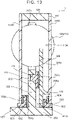
- FIG. 13 is a schematic sectional view schematically illustrating the configuration of the damper device 1 according to the sixth embodiment.
- FIG. 14 is a schematic view schematically illustrating the relationship between a disk plate 100 and a control plate 300 in the damper device 1 according to the sixth embodiment as enlarged.
- FIG. 13 indicates in a simple manner that the damper device 1 according to the sixth embodiment has the following configuration that is different from that of the damper device 1 according to the first embodiment, focusing on the region I.
- FIG. 13 indicates in a simple manner that the damper device 1 according to the sixth embodiment has the following configuration that is different from that of the damper device 1 according to the first embodiment, focusing on the region I.
- the configuration of the damper device 1 according to the sixth embodiment is generally the same as that of the damper device 1 according to the first embodiment discussed above, the configuration of the disk plate 100, the hub 200, the control plate 300, the first sliding portion 600, and the second sliding portion 700 is different from that according to the first embodiment discussed above.
- Components of the damper device 1 according to the sixth embodiment that are the same as those of the damper device 1 according to the first embodiment will not be described in detail.
- the control plate 300 of the damper device 1 according to the sixth embodiment is configured such that the axially extending portions 303a to 303d are housed in the disk plate 100, rather than being housed in the groove portions 208a to 208d, respectively, of the hub 200, unlike the first embodiment. Specifically, as illustrated in FIG.
- the first plate 100A of the damper device 1 is provided with a housing groove portion 130 (housing groove portions 130a to 130d) that houses each of the axially extending portions 303a to 303d in correlation with each of the regions I to IV
- the housing groove portions 130a to 130d may be integrally provided on the radially inner side of the first housing region 102a, the second housing region 102b, the third housing region 102c, and the fourth housing region 102d, which are provided in the first plate 100A, respectively, as with the groove portions 208a to 208d according to the first embodiment which are provided continuously with the window holes 206a to 206d, respectively, of the hub 200, or may be independently provided in the first plate 100A.
- FIG. 14 illustrates an example in which the housing groove portion 130a is provided independently of the first housing region 102a.
- the axially extending portions 303a to 303d of the control plate 300 are housed at a position proximate to the wall portion 130w that defines the housing groove portions 130a to 130d with a gap with a predetermined size formed therefrom. This corresponds to the axially extending portions 303a to 303d being housed at a position proximate to the wall portion 208w in the first embodiment.
- the groove portions 208a to 208d of the hub 200 of the damper device 1 according to the sixth embodiment may be omitted, since the function of housing the axially extending portions 303a to 303d of the control plate 300 is not required.
- an engagement hole 210 in which the second sliding portion 700 is engaged is separately formed in the hub 200. Consequently, the second sliding portion 700 is configured to be engaged with the hub 200 so that the second sliding portion 700 can be rotated together with the hub 200.
- the first sliding portion 600 of the damper device 1 according to the sixth embodiment is basically configured similarly to that according to the first embodiment, but is disposed at a position close to the rotational axis O.
- the damper device 1 according to the sixth embodiment configured as described above basically operates similarly to that according to the first embodiment.
- the relationship between the control plate 300 and the hub 200 according to the first embodiment described with reference to FIGS. 7A to 7F is replaced with the relationship between the control plate 300 and the disk plate 100 (first plate 100A) in the sixth embodiment.
- the size of the gap between each of the axially extending portions 303a to 303d of the control plate 300 and the wall portion 130w of the corresponding one of the housing groove portions 130a to 130d is gradually increased so that the two do not abut against each other.
- the control plate 300 is not affected by the rotation of the disk plate 100 relative to the hub 200, and is not rotated relative to the hub 200.
- the control plate 300 is rotated relative to the disk plate 100 (the disk plate 100 is rotated relative to the control plate 300).
- first sliding torque is generated between the radially extending portion 302 of the control plate 300 and the first sliding surface 602a of the first sliding portion 600.
- the size of the gap between each of the axially extending portions 303a to 303d of the control plate 300 and the wall portion 130w of the corresponding one of the housing groove portions 130a to 130d is gradually reduced so that the two finally abut against each other at a torsion angle of ⁇ 3°.
- a gap is present between the axially extending portions 303a to 303d and the wall portions 130w also at torsion angles of 0° to ⁇ 3°, and therefore the control plate 300 is not affected by the rotation of the disk plate 100 relative to the hub 200, and is not rotated relative to the hub 200.
- first sliding torque is generated between the radially extending portion 302 of the control plate 300 and the first sliding surface 602a of the first sliding portion 600.
- control plate 300 is rotated together with the disk plate 100. Consequently, the control plate 300 is rotated relative to the hub 200, and second sliding torque is generated between the radially extending portions 302a to 302d of the control plate 300 and the second sliding surface 702b of the second sliding portion 700.
- the second sliding torque is set to be larger than the first sliding torque.
- the thrust member 500 generates third sliding torque, as in the first embodiment. Consequently, in the sixth embodiment, the resultant torque of the third sliding torque and the first sliding torque is used as "small hysteresis torque", and the resultant torque of the third sliding torque and the second sliding torque is used as "large hysteresis torque”.
- FIG. 15 is a schematic sectional view schematically illustrating the configuration of the damper device 1 according to the seventh embodiment.
- FIG. 15 indicates in a simple manner that the damper device 1 according to the seventh embodiment has the following configuration that is different from that of the damper device 1 according to the first embodiment, focusing on the region I.
- FIG. 15 While some constituent elements that are common to the damper device 1 according to the first embodiment illustrated in FIGS. 3 etc. and the damper device 1 according to the seventh embodiment illustrated in FIG. 15 are expressed slightly differently in FIG. 15 for convenience, it should be understood that the shape etc. of the constituent elements according to the two embodiments are basically common, except for the following different configuration.
- the configuration of the damper device 1 according to the seventh embodiment is generally the same as that of the damper device 1 according to the first embodiment discussed above, the configuration of the disk plate 100, the hub 200, the control plate 300, the thrust member 500, the first sliding portion 600, and the second sliding portion 700 is different from that according to the first embodiment discussed above.
- the configuration of the damper device 1 according to the seventh embodiment is generally the same as that of the damper device 1 according to the sixth embodiment discussed above.
- portions of the damper device 1 according to the seventh embodiment that are different from the damper device 1 according to the sixth embodiment will be basically described mainly, and the other portions thereof will not be described in detail.
- the thrust member 500 of the damper device 1 according to the seventh embodiment is provided with a fourth elastic member 505, as in the second embodiment. Consequently, the second surface 502y of the thrust member 500 is pressed against the hub 200 (disk portion 205) by the biasing force of the fourth elastic member 505, which makes it possible to generate the third sliding torque discussed above reliably and efficiently when the disk plate 100 and the hub 200 are rotated relative to each other.
- the first plate 100A As described in relation to the second embodiment discussed above, as a reaction force of the biasing force of the fourth elastic member 505 is transferred to the second plate 100B, the first plate 100A is biased in the direction of moving closer to the control plate 300 (in the leftward direction on the drawing sheet of FIG. 15 ). Consequently, the first plate 100A is pressed against the first sliding portion 600, and the control plate 300 is pressed against the first sliding portion 600. That is, the first sliding portion 600 according to the seventh embodiment does not include the second elastic member 604.
- first sliding torque can be generated between the first plate 100A and the first sliding portion 600 (first sliding surface 602a) and between the first sliding portion 600 (first sliding surface 602a) and the radially extending portion 302 of the control plate 300 when the control plate 300 and the disk plate 100 are rotated relative to each other.
- the second sliding portion 700 of the damper device 1 according to the seventh embodiment is configured to be engaged with the control plate 300 to be rotatable together with the control plate 300, unlike the sixth embodiment.
- the second sliding portion 700 is configured to be engaged (fitted) in an engagement hole 305 provided in the radially extending portion 302 of the control plate 300.
- second sliding torque can be generated between the hub 200 (disk portion 205) and the second sliding surface 702a of the second sliding portion 700 when the control plate 300 and the hub 200 are rotated relative to each other, as in the sixth embodiment.
- the second sliding torque is set to be larger than the first sliding torque.
- the resultant torque of the third sliding torque and the first sliding torque is used as "small hysteresis torque"
- the resultant torque of the third sliding torque and the second sliding torque is used as "large hysteresis torque”.
- FIG. 16 is a schematic sectional view schematically illustrating the configuration of the damper device 1 according to the eighth embodiment.
- FIG. 16 indicates in a simple manner that the damper device 1 according to the eighth embodiment has the following configuration that is different from that of the damper device 1 according to the first embodiment, focusing on the region I.
- FIG. 16 While some constituent elements that are common to the damper device 1 according to the first embodiment illustrated in FIGS. 3 etc. and the damper device 1 according to the eighth embodiment illustrated in FIG. 16 are expressed slightly differently in FIG. 16 for convenience, it should be understood that the shape etc. of the constituent elements according to the two embodiments are basically common, except for the following different configuration.
- the configuration of the damper device 1 according to the eighth embodiment is generally the same as that of the damper device 1 according to the first embodiment discussed above, the configuration of the disk plate 100, the hub 200, the control plate 300, the first sliding portion 600, and the second sliding portion 700 is different from that according to the first embodiment discussed above.
- the configuration of the damper device 1 according to the eighth embodiment is generally the same as that of the damper device 1 according to the sixth embodiment discussed above.
- portions of the damper device 1 according to the eighth embodiment that are different from the damper device 1 according to the sixth embodiment will be basically described mainly, and the other portions thereof will not be described in detail.
- the second sliding portion 700 of the damper device 1 according to the eighth embodiment is provided with a third elastic member 705 that biases the second sliding surface 702a in the direction of pressing the second sliding surface 702a against the hub 200 (disk portion 205) (in the leftward direction on the drawing sheet of FIG. 16 ), as in the third embodiment.
- the second sliding portion 700 may be engaged with the control plate 300. Consequently, second sliding torque can be generated reliably and efficiently between the hub 200 and the second sliding surface 702a when the control plate 300 and the hub 200 are rotated relative to each other.
- first plate 100A is biased in the direction of moving away from the control plate 300 (in the rightward direction on the drawing sheet of FIG. 16 ) based on the reaction force discussed above, and the second plate 100B integrated with the first plate 100A via the rivets 120 is biased in the direction of moving closer to the hub 200 (in the rightward direction on the drawing sheet of FIG. 16 ). Consequently, the third sliding torque discussed above can be generated reliably and efficiently on the first surface 502x and the second surface 502y of the thrust member 500.
- the second sliding torque is set to be larger than the first sliding torque.
- the resultant torque of the third sliding torque and the first sliding torque is used as "small hysteresis torque"
- the resultant torque of the third sliding torque and the second sliding torque is used as "large hysteresis torque”.
- FIG. 17 is a schematic sectional view schematically illustrating the configuration of the damper device 1 according to the ninth embodiment.
- FIG. 17 indicates in a simple manner that the damper device 1 according to the ninth embodiment has the following configuration that is different from that of the damper device 1 according to the first embodiment, focusing on the region I.
- FIG. 17 While some constituent elements that are common to the damper device 1 according to the first embodiment illustrated in FIGS. 3 etc. and the damper device 1 according to the ninth embodiment illustrated in FIG. 17 are expressed slightly differently in FIG. 17 for convenience, it should be understood that the shape etc. of the constituent elements according to the two embodiments are basically common, except for the following different configuration.
- the configuration of the damper device 1 according to the ninth embodiment is generally the same as that of the damper device 1 according to the first embodiment discussed above, the configuration of the disk plate 100, the hub 200, the control plate 300, the first sliding portion 600, and the second sliding portion 700 is different from that according to the first embodiment discussed above.
- the configuration of the damper device 1 according to the ninth embodiment is generally the same as that of the damper device 1 according to the seventh embodiment discussed above.
- portions of the damper device 1 according to the ninth embodiment that are different from the damper device 1 according to the seventh embodiment will be basically described mainly, and the other portions thereof will not be described in detail.
- the first sliding portion 600 of the damper device 1 according to the ninth embodiment includes a second elastic member 604 that biases the first sliding surface 602a in the direction of moving closer to the first plate 100A (in the rightward direction on the drawing sheet of FIG. 17 ).
- the first sliding portion 600 according to the ninth embodiment may be engaged with the control plate 300 to be rotatable together with the control plate 300. Consequently, first sliding torque can be generated reliably and efficiently when the control plate 300 and the disk plate 100 are rotated relative to each other.
- the first plate 100A is biased in the direction of moving away from the control plate 300 (in the rightward direction on the drawing sheet of FIG. 17 ) by the biasing force of the second elastic member 604 discussed above.
- the biasing force is transferred also to the second plate 100B integrated with the first plate 100A via the rivets 120, and therefore the second plate 100B is biased in the direction of moving closer to the hub 200 (in the rightward direction on the drawing sheet of FIG. 17 ). Consequently, the third sliding torque discussed above can be generated reliably and efficiently on the first surface 502x and the second surface 502y of the thrust member 500.
- the second sliding torque is set to be larger than the first sliding torque.
- the resultant torque of the third sliding torque and the first sliding torque is used as "small hysteresis torque"
- the resultant torque of the third sliding torque and the second sliding torque is used as "large hysteresis torque”.
- FIG. 18 is a schematic sectional view schematically illustrating the configuration of the damper device 1 according to the tenth embodiment.
- FIG. 18 indicates in a simple manner that the damper device 1 according to the tenth embodiment has the following configuration that is different from that of the damper device 1 according to the first embodiment, focusing on the region I.
- FIG. 18 While some constituent elements that are common to the damper device 1 according to the first embodiment illustrated in FIGS. 3 etc. and the damper device 1 according to the tenth embodiment illustrated in FIG. 18 are expressed slightly differently in FIG. 18 for convenience, it should be understood that the shape etc. of the constituent elements according to the two embodiments are basically common, except for the following different configuration.
- the damper device 1 according to the tenth embodiment is configured in substantially the same manner as that according to the seventh embodiment discussed above, the first sliding portion 600 and the second sliding portion 700 are formed integrally with the control plate 300, as in the fifth embodiment. That is, the control plate 300, the first sliding portion 600, and the second sliding portion 700 are formed as one integral structure.
- the thus formed integral structure can be grasped as a control plate 300y (the control plate according to the tenth embodiment is referred to as a "control plate 300y" for convenience) that provides both the function of the first sliding portion 600 and the function of the second sliding portion 700 according to the seventh embodiment.
- control plate 300y can include, on the radially extending portion 302, the first sliding surface 602a that is directly slid with respect to the inner surface 110A of the first plate 100A to generate first sliding torque and the second sliding surface 702a that is directly slid with respect to the hub 200 (disk portion 205) to generate second sliding torque. Consequently, the damper device 1 according to the tenth embodiment can operate in the same manner as the damper device 1 according to the seventh embodiment.
- the second sliding torque is set to be larger than the first sliding torque.
- the resultant torque of the third sliding torque and the first sliding torque is used as "small hysteresis torque"
- the resultant torque of the third sliding torque and the second sliding torque is used as "large hysteresis torque”.
- control plate 300 While an example in which the control plate 300 is housed in the first housing space 100x has been discussed in detail in relation to all the embodiments described above, the control plate 300 may be housed in the second housing space 100y as discussed above. In this case, constituent elements disposed in the first housing space 100x and constituent elements disposed in the second housing space 100y should be interchanged with each other in all the embodiments.
Landscapes
- Engineering & Computer Science (AREA)
- General Engineering & Computer Science (AREA)
- Mechanical Engineering (AREA)
- Physics & Mathematics (AREA)
- Acoustics & Sound (AREA)
- Aviation & Aerospace Engineering (AREA)
- Mechanical Operated Clutches (AREA)
Abstract
Description
- The disclosure of
JP 2021 - 101 389 A filed on June 18, 2021 - The technology disclosed herein relates to a damper device.
- In vehicles etc., a damper device is provided in a torque transfer path between a drive source such as an engine and a transmission to absorb vibration of torque transferred from the drive source to the transmission. The damper device is incorporated in a clutch device, for example.
- A damper device with a common configuration is known to include a coil spring interposed between a disk plate as an input member and a hub as an output member, which are rotatable relative to each other, to absorb and damp torque fluctuations using elastic deformation of the coil spring. It is also known to further absorb the torque fluctuations by generating sliding torque (hysteresis torque) based on relative rotation between the disk plate and the hub, in addition to using the elastic deformation of the coil spring.
-
JP 6 471 486 B reference sign 1 inJP 6 471 486 B reference sign 2 inJP 6 471 486 B JP 6 471 486 B JP 6 471 486 B JP 6 471 486 B - In the damper device described in
JP 6 471 486 B - Thus, a damper device with a short axial length is provided through various embodiments. In addition, a damper device that can stably generate a variety of hysteresis torques is also provided.
- A first aspect provides a damper device including: a first rotary body that includes at least a first plate that is rotatable about a rotational axis and a second plate that is disposed to face the first plate and that is rotatable about the rotational axis together with the first plate; a second rotary body that is rotatable relative to the first rotary body about the rotational axis; an elastic mechanism portion that elastically couples the first rotary body and the second rotary body to each other in a rotational direction; a control plate that includes a radially extending portion that extends in a radial direction to abut against the elastic mechanism portion and an axially extending portion that extends in an axial direction to be at least partially housed in one of the first rotary body and the second rotary body, the control plate being disposed in only one of a first housing space between the first plate and the second rotary body and a second housing space between the second plate and the second rotary body in the axial direction; a first sliding portion that is disposed between the first rotary body and the control plate and that is slid with respect to at least one of the first rotary body and the control plate to generate first sliding torque; and a second sliding portion that is disposed between the second rotary body and the control plate and that is slid with respect to at least one of the second rotary body and the control plate to generate second sliding torque, in which the first sliding torque and the second sliding torque are generated when the first rotary body and the second rotary body are rotated relative to each other.
- According to the first aspect, it is possible to provide a damper device with a short axial length and with the number of components thereof reduced by using a single control plate.
- In the damper device according to the second aspect, one of the first sliding torque and the second sliding torque may be larger than the other, and may be generated only when the first rotary body and the second rotary body are rotated relative to each other in a predetermined direction.
- According to the second aspect, the damper device according to the second aspect can generate small hysteresis torque (the smaller one of the first sliding torque and the second sliding torque) at all times when the first rotary body and the second rotary body are rotated relative to each other, and generate large hysteresis torque (the larger one of the first sliding torque and the second sliding torque) in the special case where the first rotary body and the second rotary body are rotated relative to each other in the predetermined direction. In this event, the magnitude of the "large hysteresis torque" can be further increased by setting one of the first sliding torque and the second sliding torque that is generated only in the special case to be larger than the other. In this manner, the damper device according to the second aspect can generate a variety of hysteresis torques. The "large hysteresis torque" discussed above can be used to suppress relatively large vibration or noise generated when an engine of a vehicle (hybrid vehicle, in particular) is started, for example.
- In the damper device according to the third aspect, the elastic mechanism portion may include a first elastic member and a pair of seat members that supports the first elastic member by holding the first elastic member between the seat members from both sides, and the radially extending portion may abut against the first elastic member or one of the pair of seat members.
- According to the third aspect, the radially extending portion can reliably abut against the elastic mechanism portion. As a result, the damper device according to the third aspect can efficiently generate the first sliding torque and the second sliding torque.
- In the damper device according to the fourth aspect, the first sliding portion may include a first sliding surface that is slid with respect to the first rotary body or the radially extending portion and a second elastic member that biases the first sliding surface in a direction of moving closer to the first rotary body or the radially extending portion.
- According to the fourth aspect, the damper device according to the fourth aspect can generate the first sliding torque reliably and efficiently.
- In the damper device according to the fifth aspect, the second sliding portion may include a second sliding surface that is slid with respect to the second rotary body or the radially extending portion and a third elastic member that biases the second sliding surface in a direction of moving closer to the second rotary body or the radially extending portion.
- According to the fifth aspect, the damper device according to the fifth aspect can generate the second sliding torque reliably and efficiently.
- In the damper device according to the sixth aspect, the first sliding portion and the second sliding portion may be formed integrally with the control plate to function as a part of the control plate; and the radially extending portion may be directly slid with respect to the first rotary body, and directly slid with respect to the second rotary body.
- According to the sixth aspect, it is possible to further reduce the number of components of the damper device according to the sixth aspect by constituting the control plate, the first sliding portion, and the second sliding portion as an integral object.
- In the damper device according to the seventh aspect, a thrust member that includes at least one of a first surface that is slid with respect to the first rotary body and a second surface that is slid with respect to the second rotary body may be further provided in one of the first housing space and the second housing space that is different from one of the first housing space and the second housing space in which the control plate is disposed.
- According to the seventh aspect, the damper device according to the seventh aspect can further generate additional hysteresis torque based on the first surface and the second surface.
- In the damper device according to the eighth aspect, the thrust member may include a fourth elastic member that biases the second surface in a direction of moving closer to the second rotary body.
- According to the eighth aspect, the damper device according to the eighth aspect can generate the additional hysteresis torque discussed above reliably and efficiently.
- A damper device with a short axial length can be provided through the various embodiments. In addition, a damper device that can stably generate a variety of hysteresis torques can also be provided.
- Features, advantages, and technical and industrial significance of exemplary embodiments of the invention will be described below with reference to the accompanying drawings, in which like numerals denote like elements, and wherein:
-
FIG. 1 is a schematic top view schematically illustrating the configuration of a damper device according to a first embodiment; -
FIG. 2 is a schematic top view schematically illustrating the configuration of the damper device illustrated inFIG. 1 from which some constituent elements have been omitted; -
FIG. 3 is a schematic sectional view schematically illustrating the configuration of the damper device illustrated inFIG. 1 taken along the line X-X; -
FIG. 4 is a schematic perspective view illustrating the configuration of the damper device according to the first embodiment as exploded into constituent elements; -
FIG. 5 is a schematic perspective view illustrating a control plate of the damper device according to the first embodiment as enlarged; -
FIG. 6 is a schematic view schematically illustrating only a region of the damper device according to the first embodiment surrounded by the dotted line inFIG. 2 as enlarged; -
FIG. 7A is a schematic top view schematically illustrating a state in which a first rotary body and a second rotary body are not rotated relative to each other in the damper device according to the first embodiment; -
FIG. 7B is a schematic top view schematically illustrating a state in which the second rotary body is rotated to the positive side relative to the first rotary body by a torsion angle of θ1° in the damper device according to the first embodiment; -
FIG. 7C is a schematic top view schematically illustrating a state in which the second rotary body is rotated to the positive side relative to the first rotary body by a torsion angle of θ2° in the damper device according to the first embodiment; -
FIG. 7D is a schematic top view schematically illustrating a state in which the second rotary body is rotated to the negative side relative to the first rotary body by a torsion angle of θ3° in the damper device according to the first embodiment; -
FIG. 7E is a schematic top view schematically illustrating a state in which the second rotary body is rotated to the negative side relative to the first rotary body by a torsion angle of θ4° in the damper device according to the first embodiment; -
FIG. 7F is a schematic top view schematically illustrating a state in which rotation of the second rotary body relative to the first rotary body is being resolved from the state inFIG. 7E in the damper device according to the first embodiment; -
FIG. 8 is a schematic characteristic chart schematically illustrating the torsional characteristics of the damper device according to the first embodiment; -
FIG. 9 is a schematic sectional view schematically illustrating the configuration of a damper device according to a second embodiment; -
FIG. 10 is a schematic sectional view schematically illustrating the configuration of a damper device according to a third embodiment; -
FIG. 11 is a schematic sectional view schematically illustrating the configuration of a damper device according to a fourth embodiment; -
FIG. 12 is a schematic sectional view schematically illustrating the configuration of a damper device according to a fifth embodiment; -
FIG. 13 is a schematic sectional view schematically illustrating the configuration of a damper device according to a sixth embodiment; -
FIG. 14 is a schematic view schematically illustrating the relationship between a disk plate and a control plate in the damper device according to the sixth embodiment as enlarged; -
FIG. 15 is a schematic sectional view schematically illustrating the configuration of a damper device according to a seventh embodiment; -
FIG. 16 is a schematic sectional view schematically illustrating the configuration of a damper device according to an eighth embodiment; -
FIG. 17 is a schematic sectional view schematically illustrating the configuration of a damper device according to a ninth embodiment; and -
FIG. 18 is a schematic sectional view schematically illustrating the configuration of a damper device according to a tenth embodiment. - Various embodiments will be described below with reference to the accompanying drawings. Constituent requirements that are common to the drawings are denoted by like reference signs. It should be noted that a constituent element that appears in a certain drawing may be omitted in another drawing for convenience of illustration. Furthermore, it should be noted that the accompanying drawings are not always drawn to the correct scale.
- An overview of the overall configuration of a damper device according to a first embodiment will be described with reference to
FIGS. 1 to 6 .FIG. 1 is a schematic top view schematically illustrating the configuration of adamper device 1 according to the first embodiment.FIG. 2 is a schematic top view schematically illustrating the configuration of thedamper device 1 illustrated inFIG. 1 from which some constituent elements have been omitted.FIG. 3 is a schematic sectional view schematically illustrating the configuration of thedamper device 1 illustrated inFIG. 1 taken along the line X-X.FIG. 4 is a schematic perspective view illustrating the configuration of thedamper device 1 according to the first embodiment as exploded into constituent elements.FIG. 5 is a schematic perspective view illustrating acontrol plate 300 of thedamper device 1 according to the first embodiment as enlarged.FIG. 6 is a schematic view schematically illustrating only a region of thedamper device 1 according to the first embodiment surrounded by the dotted line inFIG. 2 as enlarged. It should be noted that a pair ofseat members 420 of anelastic mechanism portion 400 to be discussed later is not illustrated inFIG. 6 for convenience, and that the relationship of abutment between constituent elements (e.g. between theelastic mechanism portion 400 and adisk plate 100 and between theelastic mechanism portion 400 and a hub 200) is not illustrated accurately. - The
damper device 1 according to the first embodiment is provided in a power transfer path between a drive source (not illustrated) such as an engine or a motor and a transmission etc., and receives power from the drive source via aflywheel 2 and transfers (outputs) the power to the transmission etc. (seeFIG. 3 ). - The
damper device 1 absorbs and damps torque vibration. As illustrated inFIGS. 1 to 5 , thedamper device 1 mainly includes adisk plate 100 as a first rotary body to which power is transferred from theflywheel 2, ahub 200 as a second rotary body, acontrol plate 300, anelastic mechanism portion 400, athrust member 500, a first slidingportion 600, and a second slidingportion 700. Herein, the axial direction means a direction that extends in parallel with a rotational axis O, the radial direction means a direction that is orthogonal to the rotational axis O, and the circumferential direction means a direction that circulates around the rotational axis O. - The
flywheel 2 is an annular plate member fixed by abolt 3 to a drive shaft Z connected to the drive source. - As illustrated in
FIG. 3 , power transferred from the drive shaft Z to theflywheel 2 is transferred to thedisk plate 100 via acover plate 10 fixed to theflywheel 2 by abolt 4 to rotate together with theflywheel 2 and afirst friction material 20. Apressure plate 30 is fixed to thecover plate 10. Thecover plate 10 and thepressure plate 30 are configured to rotate together with each other. Further, asupport plate 11 is fixed to theflywheel 2 together with thecover plate 10 by thebolt 4. Thesupport plate 11 supports adisk spring 40. Thedisk spring 40 biases thepressure plate 30 so as to be pressed against alining plate 101 of thedisk plate 100, to be discussed later, via asecond friction material 21, and transfers the power transferred to theflywheel 2 to the disk plate 100 (lining plate 101) together with thecover plate 10. - The
support plate 11, thepressure plate 30, and thedisk spring 40 can function as a limiter that causes slipping (blocks power transfer from thecover plate 10 and thepressure plate 30 to the disk plate 100) when thedamper device 1 cannot absorb torque fluctuations in the torsional direction. The limiter may be combined with a structure known in the art. - In the
damper device 1, as discussed above, power from the drive source such as an engine or a motor is transferred via theflywheel 2 to thedisk plate 100 as a first rotary body disposed most upstream in the power transfer path. Thedisk plate 100 is formed from a metal material, for example, and provided so as to be rotatable about the rotational axis O with thehub 200 as the second rotary body, to be discussed later, etc. interposed as illustrated inFIGS. 1 to 4 . Thedisk plate 100 includes afirst plate 100A and asecond plate 100B as a pair of substantially disk-shaped plate members provided on both sides of thehub 200 in the axial direction (with thesecond plate 100B disposed to face thefirst plate 100A in the axial direction). As illustrated inFIGS. 3 and4 , thefirst plate 100A and thesecond plate 100B are shaped to be symmetrical to each other in the axial direction, and coupled to each other by a plurality ofrivets 120 provided in the vicinity of the outer periphery thereof with the substantiallyannular lining plate 101, which can appropriately adjust the positions of the two plates in the axial direction, interposed therebetween so as to be rotatable together with each other. - When power from the drive source such as an engine or a motor is transferred from the
cover plate 10 and thepressure plate 30 to thelining plate 101 via thefirst friction material 20 and thesecond friction material 21 provided on thelining plate 101, the power is transferred from thelining plate 101 to thefirst plate 100A and thesecond plate 100B in the vicinity of therivets 120. - The
first plate 100A and thesecond plate 100B cooperate with each other to have an axially swelling shape so as to form housing regions (four housing regions are illustrated in the example illustrated inFIG. 1 ) that house theelastic mechanism portion 400, to be discussed later, in correlation with regions I to IV as illustrated inFIGS. 1 and2 . Each of the housing regions extends substantially linearly or substantially arcuately along the circumferential direction of thedisk plate 100 in order to house a firstelastic member 410 of theelastic mechanism portion 400 that extends along the circumferential direction of thedisk plate 100 and a pair of seat members 420 (aseat member 420A and aseat member 420B). The regions I to IV refer to the four regions each having a fan shape of approximately 90 degrees, as illustrated inFIG. 1 , when thedamper device 1 is seen from above. - More specifically, with reference to
FIG. 1 , thefirst plate 100A and thesecond plate 100B form afirst housing region 102a, asecond housing region 102b, athird housing region 102c, and afourth housing region 102d that extend along the circumferential direction in correlation with the regions I to IV, respectively. As discussed later, thehub 200 is provided withwindow holes first housing region 102a, thesecond housing region 102b, thethird housing region 102c, and thefourth housing region 102d, respectively. - Focusing on the region IV, as illustrated in
FIG. 1 , thefirst plate 100A and thesecond plate 100B include one end surface (fourth one end surface) 104d1 and the other end surface (fourth other end surface) 104d2 that faces the one end surface 104d1 as side walls that surround thefourth housing region 102d. The fourth one end surface 104d1 and the fourth other end surface 104d2 extend along the axial direction of thedisk plate 100, by way of example. - Likewise, focusing on the region I, the
first plate 100A and thesecond plate 100B include one end surface (first one end surface) 104a1 and the other end surface (first other end surface) 104a2 that faces the one end surface 104a1 as side walls that surround thefirst housing region 102a. Focusing on the region II, thefirst plate 100A and thesecond plate 100B include one end surface (second one end surface) 104b1 and the other end surface (second other end surface) 104b2 that faces the one end surface 104b1 as side walls that surround thesecond housing region 102b. Focusing on the region III, thefirst plate 100A and thesecond plate 100B include one end surface (third one end surface) 104c1 and the other end surface (third other end surface) 104c2 that faces the one end surface 104c1 as side walls that surround thethird housing region 102c. The side walls abut against (are engaged with) theelastic mechanism portion 400 to be discussed later. - As illustrated in
FIG. 3 , thelining plate 101 of thedisk plate 100 is disposed at the same axial position (on the same line in the radial direction) as thehub 200. Thus, as illustrated inFIGS. 2 and4 , anotch 105 that allows movement (relative rotation) of thehub 200 in the circumferential direction is provided in each of the regions I to IV of thelining plate 101. The outer edge portion of thenotch 105 functions as a regulatingportion 106 that regulates excessive relative rotation of thehub 200. - An
inner surface 110A of thefirst plate 100A can support a secondelastic member 604 that may form a part of the first slidingportion 600 to be discussed later. As discussed later, when the first slidingportion 600 is provided between thesecond plate 100B and thehub 200, aninner surface 110B of thesecond plate 100B can support the secondelastic member 604. - The other details of the
first plate 100A and thesecond plate 100B will be discussed later as appropriate. - The
hub 200 as the second rotary body functions as an output member of thedamper device 1, is formed from a metal material, for example, has a substantially disk-like shape as a whole, and is provided as interposed between thefirst plate 100A and thesecond plate 100B so as to be rotatable relative to the disk plate 100 (thefirst plate 100A and thesecond plate 100B) about the rotational axis O. As illustrated inFIGS. 3 and4 , thehub 200 has a throughhole 203 formed in acylindrical portion 202 that is substantially cylindrical. An input shaft (not illustrated) of the transmission can be inserted through the throughhole 203 to be splined with thehub 200. Thehub 200 is provided with adisk portion 205 that extends radially outward from thecylindrical portion 202. - As discussed above, the
disk portion 205 is provided with thewindow holes first housing region 102a, thesecond housing region 102b, thethird housing region 102c, and thefourth housing region 102d, respectively, and provided at equal intervals. Thewindow holes 206a to 206d provided in thehub 200 are each provided in correspondence with theelastic mechanism portion 400 to be discussed later. That is, theelastic mechanism portion 400 is housed in each of thewindow holes 206a to 206d. - As illustrated in
FIG. 2 , thewindow hole 206a, which is provided in correlation with the region I, has a one-end engagement portion (first one-end engagement portion) 206a1 and an other-end engagement portion (first other-end engagement portion) 206a2 that faces the one-end engagement portion 206a1, and abuts against (is engaged with) theelastic mechanism portion 400. Likewise, thewindow hole 206b, which is provided in correlation with the region II, has a one-end engagement portion (second one-end engagement portion) 206bi and an other-end engagement portion (second other-end engagement portion) 206b2 that faces the one-end engagement portion 206bi, and abuts against (is engaged with) theelastic mechanism portion 400. Thewindow hole 206c, which is provided in correlation with the region III, has a one-end engagement portion (third one-end engagement portion) 206c1 and an other-end engagement portion (third other-end engagement portion) 206c2 that faces the one-end engagement portion 206c1, and abuts against (is engaged with) theelastic mechanism portion 400. Thewindow hole 206d, which is provided in correlation with the region IV, has a one-end engagement portion (fourth one-end engagement portion) 206d1 and an other-end engagement portion (fourth other-end engagement portion) 206d2 that faces the one-end engagement portion 206di, and abuts against (is engaged with) theelastic mechanism portion 400. - Each of the
window holes 206a to 206d "abutting against theelastic mechanism portion 400" means that each of thewindow holes 206a to 206d abuts against the firstelastic member 410 or the pair ofseat members 420 to be discussed later. - Protruding
portions disk portion 205 in correlation with the regions I to IV, respectively. The protrudingportions 207a to 207d are each housed in thenotch 105 provided in thelining plate 101 such that thehub 200 is rotatable relative to thedisk plate 100. When thehub 200 is relatively rotated by a predetermined torsion angle, the protrudingportions 207a to 207d each abut against the regulatingportion 106, which is the outer edge portion of thenotch 105, to regulate excessive relative rotation of thehub 200. - As illustrated in
FIGS. 2 to 4 ,groove portions portions 303a to 303d of thecontrol plate 300, to be discussed later, are provided on the radially inner side of thewindow holes groove portions 208a to 208d are provided continuously (integrally) with thewindow holes 206a to 206d, respectively, in thedamper device 1 according to the first embodiment, this is not limiting. Thegroove portions 208a to 208d may be provided in any portion of thedisk portion 205. - The
control plate 300 is formed from a metal material such as spring steel, for example, and has a substantially annular shape as a whole. Thedamper device 1 according to the embodiment is provided with only onecontrol plate 300. Thecontrol plate 300 is disposed in only one of afirst housing space 100x, which is provided between thefirst plate 100A and thehub 200, and asecond housing space 100y, which is provided between thesecond plate 100B and thehub 200, in the axial direction. In the example illustrated inFIG. 3 , thecontrol plate 300 is disposed in thefirst housing space 100x. - As illustrated in
FIGS. 2 to 5 , thecontrol plate 300 mainly includes amain portion 301 provided in a substantially annular shape, a radially extending portion 302 that extends in the radial direction from themain portion 301 to abut against theelastic mechanism portion 400 to be discussed later, and an axially extending portion 303 that extends in the axial direction to be at least partially housed in the hub 200 (a case where the axially extending portion 303 is partially housed in the firstrotary body 100 will be discussed later). The radially extending portion 302 includes aradially extending portion 302a in the region I, aradially extending portion 302b in the region II, aradially extending portion 302c in the region III, and aradially extending portion 302d in the region IV, provided in correspondence with the regions I to IV, respectively, discussed above. Likewise, the axially extending portion 303 includes anaxially extending portion 303a in the region I, anaxially extending portion 303b in the region II, anaxially extending portion 303c in the region III, and anaxially extending portion 303d in the region IV, provided in correspondence with the regions I to IV, respectively, discussed above. - As illustrated in
FIG. 2 etc., theradially extending portions 302a to 302d are provided in correlation with the regions I to IV, respectively. Theradially extending portion 302a is provided so as to abut against the first elastic member 410 (or one of theseat member 420A and theseat member 420B that constitute the pair of seat members 420) housed in thefirst housing region 102a (window hole 206a). Theradially extending portion 302b is provided so as to abut against the first elastic member 410 (or one of theseat member 420A and theseat member 420B that constitute the pair of seat members 420) housed in thesecond housing region 102b (window hole 206b). Theradially extending portion 302c is provided so as to abut against the first elastic member 410 (or one of theseat member 420A and theseat member 420B that constitute the pair of seat members 420) housed in thethird housing region 102c (window hole 206c). Theradially extending portion 302d is provided so as to abut against the first elastic member 410 (or one of theseat member 420A and theseat member 420B that constitute the pair of seat members 420) housed in thefourth housing region 102d (window hole 206d). - The length over which the
radially extending portions 302a to 302d extend in the radial direction is not specifically limited as long as a sufficient contact area can be secured for contact with the elastic mechanism portion 400 (the firstelastic member 410 or one of theseat member 420A and theseat member 420B that constitute the pair of seat members 420). - When the
control plate 300 is disposed in thefirst housing space 100x as illustrated inFIG. 3 , theradially extending portions 302a to 302d face both thefirst plate 100A and thehub 200 in the axial direction. Thus, theradially extending portions 302a to 302d have a surface that is in sliding contact with the first slidingportion 600, to be discussed later, disposed between thefirst plate 100A and thecontrol plate 300 to generate first sliding torque. - As illustrated in
FIGS. 2 to 6 , theaxially extending portions 303a to 303d are provided in correlation with the regions I to IV, respectively. Theaxially extending portion 303a is housed in thegroove portion 208a provided on the radially inner side of thewindow hole 206a. Theaxially extending portion 303b is housed in thegroove portion 208b provided on the radially inner side of thewindow hole 206b. Theaxially extending portion 303c is housed in thegroove portion 208c provided on the radially inner side of thewindow hole 206c. Theaxially extending portion 303d is housed in thegroove portion 208d provided on the radially inner side of thewindow hole 206d. - As illustrated in
FIG. 6 , theaxially extending portion 303a is housed at a position proximate to awall portion 208w that defines thegroove portion 208a (a position at least off the center position of thegroove portion 208a). Theaxially extending portion 303b, theaxially extending portion 303c, and theaxially extending portion 303d are also housed at a similar position to theaxially extending portion 303a in thecorresponding groove portions - The
axially extending portions 303a to 303d are not engaged or fitted by any mechanism with thehub 200 in thecorresponding groove portions 208a to 208d, respectively, and thehub 200 and thecontrol plate 300 are configured to be rotatable together with each other only in a predetermined case. Thus, thecontrol plate 300 and thehub 200 are not rotated together with each other at all times. - The "predetermined case" mentioned above will be described. When the
hub 200 is rotated in a predetermined direction (e.g. L direction (counterclockwise direction) inFIGS. 1 and2 ) relative to thedisk plate 100 by a predetermined torsion angle or more, for example, theaxially extending portions 303a to 303d each abut against thewall portion 208w that defines thegroove portions 208a to 208d, respectively. Consequently, thecontrol plate 300 is rotated in the predetermined direction (e.g. L direction (counterclockwise direction) inFIGS. 1 and2 ) relative to thedisk plate 100 together with thehub 200 only when thehub 200 is rotated in the predetermined direction (L direction inFIGS. 1 and2 ) relative to thedisk plate 100 by the predetermined torsion angle or more. Consequently, theradially extending portion 302a can be in sliding contact with a sliding surface (first sliding surface) 602a of the first slidingportion 600, to be discussed later, to generate first sliding torque. Likewise, theradially extending portions 302b to 302d can also be in sliding contact with the first slidingsurface 602a of the first slidingportion 600 to generate first sliding torque. The mechanism that allows thecontrol plate 300 and thehub 200 to rotate together with each other will also be discussed in detail later. - In cases other than the case where the
control plate 300 and thehub 200 rotate together with each other as discussed above, on the other hand, thehub 200 is basically rotated relative to thecontrol plate 300. In such cases, the second slidingportion 700, to be discussed later, disposed between thehub 200 and thecontrol plate 300 can be slid with respect to thehub 200, or slid with respect to thecontrol plate 300, to generate second sliding torque. - Preferably, a commonly known friction material is applied separately, or a predetermined surface treatment is applied, to surfaces of the
radially extending portions 302a to 302d that are in sliding contact with the first slidingsurface 602a of the first slidingportion 600, in order to increase (or decrease) the magnitude of the first sliding torque. Consequently, it is possible to adjust the magnitude of the first sliding torque to a desired magnitude. - When the second sliding
portion 700 to be discussed later is in sliding contact with thecontrol plate 300 to generate second sliding torque, preferably, a commonly known friction material is applied separately, or a predetermined surface treatment is applied, to surfaces of theradially extending portions 302a to 302d that are in sliding contact with the second sliding portion 700 (surfaces on the opposite side in the axial direction of the surfaces that are in sliding contact with the first slidingsurface 602a of the first sliding portion 600), in order to increase (or decrease) the magnitude of the second sliding torque. - In the
damper device 1 according to the first embodiment illustrated inFIGS. 1 to 6 , the first sliding torque generated only in the "predetermined case" discussed above is set, as appropriate, so as to be larger than the second sliding torque using the friction material, surface treatment, etc. discussed above. - While the
elastic mechanism portion 400 is mainly constituted from the firstelastic member 410 and the pair of seat members 420 (theseat member 420A and theseat member 420B) that supports the firstelastic member 410 by holding the firstelastic member 410 therebetween from both sides in each of the regions I to IV as illustrated inFIGS. 1 to 4 and6 , the pair ofseat members 420 may be omitted. While one firstelastic member 410 may be disposed in each of the regions I to IV as illustrated inFIGS. 1 to 4 , two or more firstelastic members 410 may be disposed in series with each other. - A common coil spring can be used as the first
elastic member 410, by way of example. The form, structure, etc. of theseat member 420A and theseat member 420B are not specifically limited as long as theseat members elastic member 410 as interposed therebetween from both sides. For example, seat members known in the art can be used. - In the embodiment illustrated in
FIGS. 1 to 4 , by way of example, four housing regions, namely thefirst housing region 102a, thesecond housing region 102b, thethird housing region 102c, and thefourth housing region 102d (in correspondence with which thehub 200 is provided with thewindow holes disk plate 100. Thus, one firstelastic member 410 and a pair of seat members 420 (aseat member 420A and aseat member 420B) are housed in each of the four housing regions, that is, in correlation with each of the regions I to IV - Focusing on the region I, as illustrated in
FIGS. 1 and2 , theseat member 420A is engaged with each of the first one end surface 104a1 of the disk plate 100 (thefirst plate 100A and thesecond plate 100B) and the first one-end engagement portion 206a1 provided on thehub 200. Theseat member 420B is engaged with each of the first other end surface 104a2 of the disk plate 100 (thefirst plate 100A and thesecond plate 100B) and the first other-end engagement portion 206a2 provided on thehub 200. Also for the regions II to IV, likewise, theseat member 420A and theseat member 420B that constitute the pair ofseat members 420 are engaged with thedisk plate 100 and thehub 200. - As discussed above, the
radially extending portions 302a to 302d of thecontrol plate 300 are provided so as to abut against the first elastic member 410 (or one of theseat member 420A and theseat member 420B that constitute the pair of seat members 420) in the regions I to IV, respectively, as illustrated inFIGS. 2 , etc. - With the configuration described above, the
elastic mechanism portion 400 can elastically couple thedisk plate 100 and thehub 200 to each other in the rotational direction. That is, when power from a drive source such as an engine or a motor is transferred in the order of thedisk plate 100, theelastic mechanism portion 400, and thehub 200 and thedisk plate 100 and thehub 200 are rotated relative to each other, the firstelastic member 410 of theelastic mechanism portion 400 is compressed and deformed to absorb torque fluctuations. - The
thrust member 500 is disposed in one of thefirst housing space 100x and thesecond housing space 100y discussed above that is different from the space in which thecontrol plate 300 is disposed. That is, in the first embodiment illustrated inFIGS. 1 to 6 , thecontrol plate 300 is disposed in thefirst housing space 100x, and therefore thethrust member 500 is disposed in thesecond housing space 100y, rather than thefirst housing space 100x. When thecontrol plate 300 is disposed in thesecond housing space 100y, thethrust member 500 is disposed in thefirst housing space 100x. - In the first embodiment in which the
control plate 300 is disposed in thesecond housing space 100y, thethrust member 500 is disposed between thesecond plate 100B and thehub 200 as illustrated inFIG. 3 . Thethrust member 500 is formed from a resin material, for example, and includes a substantially cylindricalfitting portion 501 and amain portion 502 that has a substantially annular shape as a whole. - As illustrated in
FIG. 3 , thefitting portion 501 corresponds to afitting hole 112 provided in thesecond plate 100B, and may be fitted (engaged) in thefitting hole 112, by way of example. Consequently, thethrust member 500 is integrated with thesecond plate 100B (disk plate 100), and rotated together with thedisk plate 100 about the rotational axis O. Thefitting portion 501 may be fitted in a different fitting hole (not illustrated) provided separately in thehub 200, for example, rather than being fitted in thefitting hole 112 provided in thesecond plate 100B, to be rotated together with thehub 200 about the rotational axis O. Alternatively, thefitting portion 501 may be configured not to be fitted with any of thesecond plate 100B and thehub 200. - As illustrated in
FIG. 3 , themain portion 502 includes afirst surface 502x that is slidable with respect to thesecond plate 100B and asecond surface 502y that is slidable with respect to thehub 200. Consequently, themain portion 502 can generate sliding torque (third sliding torque) that is different from the first sliding torque and the second sliding torque discussed above, by sliding with respect to thesecond plate 100B and/or thehub 200. - In the
damper device 1 according to the first embodiment illustrated inFIGS. 1 to 6 , as discussed later, the secondelastic member 604 of the first slidingportion 600 biases aplate portion 602 in the direction of moving closer to the control plate 300 (in the leftward direction on the drawing sheet ofFIG. 3 ). In this event, a reaction force related to the biasing is transferred from the secondelastic member 604 to thefirst plate 100A so that thefirst plate 100A is slightly biased in the direction of moving away from the control plate 300 (in the rightward direction on the drawing sheet ofFIG. 3 ). In conjunction with the biasing, thesecond plate 100B integrated with thefirst plate 100A via therivets 120 is also slightly biased in the direction of moving closer to the control plate 300 (in the rightward direction on the drawing sheet ofFIG. 3 ). Consequently, thesecond surface 502y of thethrust member 500 is pressed against thehub 200 to generate the third sliding torque discussed above. - The third sliding torque is generated at all times when the
disk plate 100 and thehub 200 are rotated relative to each other, and can be used both when "small hysteresis torque" is constituted and when "large hysteresis torque is constituted" in thedamper device 1. In thedamper device 1 according to the first embodiment illustrated inFIGS. 1 to 6 , the "small hysteresis torque" means the resultant torque of the second sliding torque discussed above and the third sliding torque, and the "large hysteresis torque" means the resultant torque of the first sliding torque discussed above and the third sliding torque. - In the first embodiment, the first sliding
portion 600 is disposed between the disk plate 100 (first plate 100A) and thecontrol plate 300, and is slid with respect to the radially extending portion 302 (radially extendingportions 302a to 302d) of thecontrol plate 300 to generate first sliding torque. - As illustrated in
FIGS. 3 and4 , the first slidingportion 600 according to the first embodiment includes a substantiallyannular plate portion 602 that includes a first slidingsurface 602a that is slid with respect to the radially extending portion 302 (radially extendingportions 302a to 302d) of thecontrol plate 300, and a secondelastic member 604 that biases the first slidingsurface 602a of theplate portion 602 in the direction of moving closer to the radially extending portion 302 of the control plate 300 (in the leftward direction on the drawing sheet ofFIG. 3 ). In the first embodiment, the first slidingportion 600 is configured such that theplate portion 602 extends in the axial direction to be engaged with thefirst plate 100A with the secondelastic member 604 supported by thefirst plate 100A. Consequently, the first slidingportion 600 is configured to be rotatable together with thedisk plate 100. Consequently, the first slidingportion 600 can generate first sliding torque with the first slidingsurface 602a pressed against the radially extending portion 302 when thecontrol plate 300 is rotated relative to thedisk plate 100. - The
plate portion 602 is formed from a resin material, a metal material constituted from a compound containing 3d transition metal, etc., for example. Preferably, a commonly known friction material is applied separately, or a predetermined surface treatment is applied, to the first slidingsurface 602a, in order to increase (or decrease) the magnitude of the first sliding torque generated through the sliding with respect to the radially extending portion 302. Consequently, it is possible to adjust the magnitude of the first sliding torque to a desired magnitude. - While a commonly known disk spring can be used as the second
elastic member 604, this is not limiting. The secondelastic member 604 biases the first slidingsurface 602a of theplate portion 602 in the direction of moving closer to the radially extending portion 302 of the control plate 300 (in the leftward direction on the drawing sheet ofFIG. 3 ), as discussed above, while being supported by thefirst plate 100A. On the other hand, a reaction force related to the biasing is transferred from the secondelastic member 604 to thefirst plate 100A. - In the first embodiment, the second sliding
portion 700 is disposed between thecontrol plate 300 and thehub 200, and is slid with respect to at least thehub 200 to generate second sliding torque. - In the first embodiment, the second sliding
portion 700 has a substantially annular shape as a whole, and includes a second slidingsurface 702a that is slidable with respect to thehub 200. Thus, in cases other than the "predetermined case" discussed above, the second slidingportion 700 is rotated relative to thehub 200, and the second slidingsurface 702a is slid with respect to thehub 200 to generate second sliding torque. - The
control plate 300 is biased in the direction of moving closer to thehub 200 in conjunction with theplate portion 602 of the first slidingportion 600 being biased in the direction of moving closer to thecontrol plate 300 by the secondelastic member 604 of the first slidingportion 600 discussed above. Thebiased control plate 300 biases the second slidingportion 700 in the direction of moving closer to thehub 200. Consequently, the second slidingsurface 702a of the second slidingportion 700 is pressed against thehub 200 to reliably generate second sliding torque. That is, the biasing force of the secondelastic member 604 is transferred sequentially to theplate portion 602, thecontrol plate 300, and the second slidingportion 700. - The second sliding
portion 700 may include a second slidingsurface 702b that may be slid with respect to thecontrol plate 300 to generate second sliding torque. When thecontrol plate 300 and the second slidingportion 700 are configured to be rotatable relative to each other, the second slidingsurface 702b and the radially extending portion 302 of thecontrol plate 300 can be slid with respect to each other to generate second sliding torque. - In the first embodiment, the second sliding
portion 700 may be configured to be engaged with thecontrol plate 300 to rotate together with thecontrol plate 300, may be configured to be engaged with neither of thecontrol plate 300 and thehub 200, or may be configured to be engaged with thefirst plate 100A, for example. - Preferably, a commonly known friction material is applied separately, or a predetermined surface treatment is applied, to the second sliding
surfaces - Next, operation of the
damper device 1 configured as described above will be described with reference toFIGS. 7A to 7F and8 .FIG. 7A is a schematic top view schematically illustrating a state in which the first rotary body (disk plate 100) and the second rotary body (hub 200) are not rotated relative to each other in thedamper device 1 according to the first embodiment.FIG. 7B is a schematic top view schematically illustrating a state in which the second rotary body (hub 200) is rotated to the positive side relative to the first rotary body (disk plate 100) by a torsion angle of θ1° in thedamper device 1 according to the first embodiment.FIG. 7C is a schematic top view schematically illustrating a state in which the second rotary body (hub 200) is rotated to the positive side relative to the first rotary body (disk plate 100) by a torsion angle of θ2° in thedamper device 1 according to the first embodiment.FIG. 7D is a schematic top view schematically illustrating a state in which the second rotary body (hub 200) is rotated to the negative side relative to the first rotary body (disk plate 100) by a torsion angle of θ3° in thedamper device 1 according to the first embodiment.FIG. 7E is a schematic top view schematically illustrating a state in which the second rotary body (hub 200) is rotated to the negative side relative to the first rotary body (disk plate 100) by a torsion angle of θ4° in thedamper device 1 according to the first embodiment.FIG. 7F is a schematic top view schematically illustrating a state in which rotation of the second rotary body (hub 200) relative to the first rotary body (disk plate 100) is being resolved from the state inFIG. 7E in thedamper device 1 according to the first embodiment.FIG. 8 is a schematic characteristic chart schematically illustrating the torsional characteristics of thedamper device 1 according to the first embodiment. InFIGS. 7A to 7F , the pair of seat members 420 (theseat member 420A and theseat member 420B) of theelastic mechanism portion 400 is not illustrated for convenience. -
FIG. 7A illustrates a state in which power from the drive source such as an engine or a motor is transferred to thedamper device 1 but in which no relative rotation is caused between thedisk plate 100 and the hub 200 (torsion angle: 0°). In this case, none of the first sliding torque, the second sliding torque, and the third sliding torque discussed above is generated. - In the state illustrated in
FIG. 7A in which no relative rotation is caused between thedisk plate 100 and thehub 200, theaxially extending portions 303a to 303d of thecontrol plate 300 are housed in thecorresponding groove portions 208a to 208d of thehub 200 at a position proximate to thewall portion 208w that defines thegroove portions 208a to 208d, respectively. That is, a gap with the same size is formed between theaxially extending portion 303a and thewall portion 208w, between theaxially extending portion 303b and thewall portion 208w, between theaxially extending portion 303c and thewall portion 208w, and between theaxially extending portion 303d and thewall portion 208w, and each of theaxially extending portions 303a to 303d does not abut against thewall portion 208w. - Next,
FIG. 7B illustrates a state in which relative rotation is caused between thedisk plate 100 and thehub 200 from the state inFIG. 7A to cause torsion of θ1° to the positive side. The positive side refers to the case where thehub 200 is rotated (moved) in the R direction (clockwise direction inFIG. 7B ) relative to thedisk plate 100, for example. In this case, thehub 200 is rotated relative to thedisk plate 100 while distorting the firstelastic members 410. At torsion angles of 0° to θ1°, the size of the gap between each of theaxially extending portions 303a to 303d and thecorresponding wall portion 208w is gradually increased, and therefore the two (the axially extending portion 303 and thewall portion 208w) still do not abut against each other. Thus, thecontrol plate 300 is not affected by the rotation of thehub 200 relative to thedisk plate 100, and is not rotated relative to thedisk plate 100. On the other hand, thecontrol plate 300 is rotated relative to the hub 200 (thehub 200 is rotated relative to the control plate 300). - In this case (the state in
FIG. 7A to the state inFIG. 7B ), as discussed above with reference toFIG. 3 , the third sliding torque discussed above is generated through the sliding between thesecond surface 502y of thethrust member 500 rotated together with thedisk plate 100 and the hub 200 (disk portion 205). The second sliding torque is generated with the second slidingsurface 702a of the second slidingportion 700 slid with respect to the hub 200 (disk portion 205) based on the relative rotation between thehub 200 and thecontrol plate 300. As discussed above, when the second slidingportion 700 is rotatable relative to thecontrol plate 300, the second sliding torque discussed above may be generated through the sliding between the slidingsurface 702b of the second slidingportion 700 and the radially extending portion 302 (radially extendingportions 302a to 302d) of thecontrol plate 300. - In the state in
FIG. 7A to the state inFIG. 7B , as described above, the resultant torque of the third sliding torque and the second sliding torque is generated as hysteresis torque, and the hysteresis torque in this case corresponds to "small hysteresis torque". - Next,
FIG. 7C illustrates a state in which the rotation of thehub 200 relative to thedisk plate 100 is further increased from the state inFIG. 7B to cause torsion of θ2° to the positive side. In this case, thehub 200 is rotated relative to thedisk plate 100 while further distorting the firstelastic members 410. At a torsion angle of θ2°, each of the protrudingportions 207a to 207d of thehub 200 abuts against the regulatingportion 106 provided on thelining plate 101. Consequently, relative rotation of thehub 200 to the positive side by more than θ2° is regulated, and therefore the torsion angle of θ2° can be grasped as the maximum torsion angle to the positive side. - At torsion angles of θ1° to θ2°, the size of the gap between each of the
axially extending portions 303a to 303d and thecorresponding wall portion 208w is further increased, and therefore the two still do not abut against each other. Thus, thecontrol plate 300 is not affected by the rotation of thehub 200 relative to thedisk plate 100, and is not rotated relative to thedisk plate 100. On the other hand, thecontrol plate 300 is rotated relative to the hub 200 (thehub 200 is rotated relative to the control plate 300). - Also in this case (the state in
FIG. 7B to the state inFIG. 7C ), the third sliding torque and the second sliding torque are generated, as when a transition is made from the state inFIG. 7A to the state inFIG. 7B . Thus, "small hysteresis torque" is generated also in the state inFIG. 7B to the state inFIG. 7C . - Next,
FIG. 7D illustrates a state in which relative rotation is caused between thedisk plate 100 and thehub 200 from the state inFIG. 7A to cause torsion of θ3° to the negative side. The negative side refers to the case where thehub 200 is rotated (moved) in the L direction (counterclockwise direction inFIG. 7D ) relative to thedisk plate 100, for example. In this case, thehub 200 is rotated relative to thedisk plate 100 while distorting the firstelastic members 410. At torsion angles of 0° to θ3°, the size of the gap between each of theaxially extending portions 303a to 303d and thecorresponding wall portion 208w is gradually reduced, and the two abut against each other (the gap is eliminated) at a torsion angle of θ3°. Thus, at torsion angles of 0° to θ3°, thecontrol plate 300 is not affected by the rotation of thehub 200 relative to thedisk plate 100, and still is not rotated relative to thedisk plate 100. On the other hand, thecontrol plate 300 is rotated relative to the hub 200 (thehub 200 is rotated relative to the control plate 300). - Each of the
radially extending portions 302a to 302d of thecontrol plate 300 basically abuts against theelastic mechanism portion 400 in each of the regions I to IV. For example, each of theradially extending portions 302a to 302d abuts against theelastic mechanism portion 400 at all times when thehub 200 is not rotated relative to the disk plate 100 (state inFIG. 7A ) and when thehub 200 is rotated relative to thedisk plate 100 to the positive side (states inFIGS. 7B and7C ). As the torsion angle is varied from 0° to θ3°, however, the relationship of abutment is sequentially resolved. That is, at torsion angles of 0° to θ3°, a gap is formed between each of theradially extending portions 302a to 302d of thecontrol plate 300 and the first elastic member 410 (elastic mechanism portion 400), and the size of the gap is sequentially increased. This is made in conjunction with the gap between each of theaxially extending portions 303a to 303d and thewall portion 208w being eliminated as discussed above. - Also in this case (the state in
FIG. 7A to the state inFIG. 7D ), the third sliding torque and the second sliding torque discussed above are generated, as when a transition is made from the state inFIG. 7A to the state inFIG. 7B . Thus, "small hysteresis torque" is generated also in the state inFIG. 7A to the state inFIG. 7D . - Next,
FIG. 7E illustrates a state in which the rotation of thehub 200 relative to thedisk plate 100 is further increased from the state inFIG. 7D to cause torsion of θ4° to the negative side. In this case, thehub 200 is rotated relative to thedisk plate 100 while further distorting the firstelastic members 410. At a torsion angle of θ4°, each of the protrudingportions 207a to 207d of thehub 200 abuts against the regulatingportion 106 provided on thelining plate 101. Consequently, relative rotation of thehub 200 to the negative side by more than θ4° is regulated, and therefore the torsion angle of θ4° can be grasped as the maximum torsion angle to the negative side. In this case, the gap formed in the state inFIG. 7D is still formed between each of theradially extending portions 302a to 302d of thecontrol plate 300 and the elastic mechanism portion 400 (first elastic member 410). - At torsion angles of θ3° to θ4°, each of the
axially extending portions 303a to 303d and thecorresponding wall portion 208w abut against each other. Thus, the control plate 300 (axially extendingportions 303a to 303d) is rotated in the L direction relative to thedisk plate 100 together with the hub 200 (integrally with the hub 200) as guided by the hub 200 (wall portion 208w). - Also in this case (the state in
FIG. 7D to the state inFIG. 7E ), thedisk plate 100 and thehub 200 are rotated relative to each other, and therefore the third sliding torque discussed above is generated, as when a transition is made from the state inFIG. 7A to the state inFIG. 7B . In this case, thecontrol plate 300 is also rotated relative to thedisk plate 100, and therefore the first sliding torque discussed above is generated between the first slidingsurface 602a of the first slidingportion 600 and the radially extending portion 302 (radially extendingportions 302a to 302d) of thecontrol plate 300 as discussed above. In this case, thehub 200 and thecontrol plate 300 are rotated together with each other, and therefore the second sliding torque is not generated. The first sliding torque generated in this case is set in advance to be larger than the second sliding torque. Such setting is made by adjusting, as appropriate, the friction coefficients of the first slidingsurface 602a and theradially extending portions 302a to 302d that generate the first sliding torque by any method discussed above. - In the state in
FIG. 7D to the state inFIG. 7E , from the above, the resultant torque of the third sliding torque and the first sliding torque is generated as hysteresis torque, and the hysteresis torque in this case corresponds to "large hysteresis torque". - Next,
FIG. 7F illustrates a state in which the rotation of thehub 200 relative to thedisk plate 100 is being resolved from the state inFIG. 7E , in the middle of a transition from a maximum torsion angle of θ4° to a torsion angle of 0° on the negative side. In this case, thehub 200 is relatively moved in the R direction toward a torsion angle of 0° while gradually resolving the torsion of the firstelastic member 410. That is, the torsion angle in the state inFIG. 7F can be considered to be a torsion angle between θ3° and θ4°, for example. - In this case, first, when the
hub 200 is relatively moved in the R direction from a torsion angle of θ4° (moved so as to resolve the relative rotation in the L direction), the relationship of abutment between each of theaxially extending portions 303a to 303d and thecorresponding wall portion 208w is resolved, and a gap is sequentially formed therebetween again. That is, rotation of thecontrol plate 300 in the R direction (rotation relative to the disk plate 100) may not be guided by thehub 200. Thus, a slight time difference is caused between the timing when the rotation of thehub 200 relative to thedisk plate 100 to the negative side is resolved and the timing when the rotation of thecontrol plate 300 relative to thedisk plate 100 to the negative side is resolved. - When the
hub 200 is relatively moved in the R direction by a predetermined angle (the predetermined angle is defined as α°, for example) in order to resolve the relative rotation to the negative side from a torsion angle of θ4° prior to the control plate 300 (without guiding the control plate 300), the gap formed in the state inFIG. 7D (andFIG. 7E ) between each of theradially extending portions 302a to 302d of thecontrol plate 300 and theelastic mechanism portion 400 is gradually reduced to be finally eliminated. Consequently, each of theradially extending portions 302a to 302d of thecontrol plate 300 and theelastic mechanism portion 400 abut against each other again. In this state, theelastic mechanism portion 400 is still distorted, and therefore theelastic mechanism portion 400 presses (biases) thecontrol plate 300 in the R direction. Consequently, thecontrol plate 300 is now rotated in the R direction relative to thedisk plate 100 based on a biasing force due to the distortion of theelastic mechanism portion 400. - The above flow will be further described. At torsion angles of θ4° to θ4 - α°, only the
hub 200 is rotated in the R direction relative to thedisk plate 100, and therefore the third sliding torque and the second sliding torque are generated as when a transition is made from the state inFIG. 7A to the state inFIG. 7B . That is, "small hysteresis torque" is generated. At torsion angles of θ4 - α° to 0°, on the other hand, not only thehub 200 but also thecontrol plate 300 is rotated in the R direction relative to thedisk plate 100, and therefore the third sliding torque and the first sliding torque are generated as when a transition is made from the state inFIG. 7D to the state inFIG. 7E . That is, "large hysteresis torque" is generated. - Based on the flow of operation of the
damper device 1 described above with reference toFIGS. 7A to 7F , the torsional characteristics of thedamper device 1 are as indicated inFIG. 8 . - The "large hysteresis torque" generated on only the negative side as discussed above, that is, hysteresis torque obtained by adding the first sliding torque and the third sliding torque, is suitably used to absorb torque fluctuations caused when an engine of a hybrid vehicle is started under any condition in a state in which the vehicle is driven by only a motor with the engine stationary, for example. On the positive side, as discussed above, the "small hysteresis torque", that is, hysteresis torque obtained by adding the second sliding torque and the third sliding torque, can be generated. In this manner, the
damper device 1 according to the first embodiment can render the axial length of thedamper device 1 short by using asingle control plate 300, generate relatively small hysteresis torque on the positive side and relatively large hysteresis torque on the negative side, and stably generate a variety of hysteresis torques. Thedamper device 1 according to the first embodiment generates first sliding torque on the radially extending portion 302 of thecontrol plate 300 via the first slidingportion 600. Thus, thedamper device 1 can be designed relatively easily from the viewpoint of the shape, structure, strength, etc. of thecontrol plate 300. - Next, the configuration of a
damper device 1 according to a second embodiment will be described with reference toFIG. 9. FIG. 9 is a schematic sectional view schematically illustrating the configuration of thedamper device 1 according to the second embodiment.FIG. 9 indicates in a simple manner that thedamper device 1 according to the second embodiment has the following configuration that is different from that of thedamper device 1 according to the first embodiment, focusing on the region I. Thus, while some constituent elements that are common to thedamper device 1 according to the first embodiment illustrated inFIGS. 3 etc. and thedamper device 1 according to the second embodiment illustrated inFIG. 9 are expressed slightly differently inFIG. 9 for convenience, it should be understood that the shape etc. of the constituent elements according to the two embodiments are common unless specifically described otherwise, except for the following different configuration. - While the configuration of the
damper device 1 according to the second embodiment is generally the same as that of thedamper device 1 according to the first embodiment discussed above, the configuration of thethrust member 500 and the first slidingportion 600 is different from that according to the first embodiment discussed above. Components of thedamper device 1 according to the second embodiment that are the same as those of thedamper device 1 according to the first embodiment will not be described in detail. - The
thrust member 500 of thedamper device 1 according to the second embodiment further includes, in addition to an integral component constituted from the substantially cylindricalfitting portion 501 and the substantially annularmain portion 502 discussed above, a fourthelastic member 505 that biases the integral component in the direction of moving closer to the hub 200 (in the rightward direction on the drawing sheet ofFIG. 9 ). While a commonly known disk spring can be used as the fourthelastic member 505, this is not limiting. - On the other hand, the first sliding
portion 600 of thedamper device 1 according to the second embodiment does not include the secondelastic member 604 which is a constituent element in the first embodiment, and is composed of only theplate portion 602. - In the
damper device 1 according to the second embodiment configured as described above, thesecond surface 502y of thethrust member 500 is pressed against the hub 200 (disk portion 205) by the biasing force of the fourthelastic member 505. Consequently, it is possible to generate the third sliding torque discussed above reliably and efficiently when thedisk plate 100 and thehub 200 are rotated relative to each other. - On the other hand, as the fourth
elastic member 505 biases thesecond surface 502y in the direction of moving closer to thehub 200, a reaction force related to the biasing is transferred from the fourthelastic member 505 to thesecond plate 100B in conjunction with the biasing. Consequently, thesecond plate 100B is slightly biased in the direction of moving away from the hub 200 (in the leftward direction on the drawing sheet ofFIG. 9 ). In conjunction with the biasing, thefirst plate 100A integrated with thesecond plate 100B via therivets 120 is also slightly biased in the direction of moving closer to the control plate 300 (in the leftward direction on the drawing sheet ofFIG. 9 ). The biasing force transferred to thefirst plate 100A may be replaced with the biasing force applied by the secondelastic member 604 according to the first embodiment. Thus, with the first slidingportion 600 of thedamper device 1 according to the second embodiment, it is possible to generate first sliding torque between the first slidingsurface 602a of the first slidingportion 600 and the radially extending portion 302 of thecontrol plate 300, even if the secondelastic member 604 which is a constituent element in the first embodiment is omitted. - Next, the configuration of a
damper device 1 according to a third embodiment will be described with reference toFIG. 10. FIG. 10 is a schematic sectional view schematically illustrating the configuration of thedamper device 1 according to the third embodiment.FIG. 10 indicates in a simple manner that thedamper device 1 according to the third embodiment has the following configuration that is different from that of thedamper device 1 according to the first embodiment, focusing on the region I. Thus, while some constituent elements that are common to thedamper device 1 according to the first embodiment illustrated inFIGS. 3 etc. and thedamper device 1 according to the third embodiment illustrated inFIG. 10 are expressed slightly differently inFIG. 10 for convenience, it should be understood that the shape etc. of the constituent elements according to the two embodiments are common unless specifically described otherwise, except for the following different configuration. - While the configuration of the
damper device 1 according to the third embodiment is generally the same as that of thedamper device 1 according to the first embodiment discussed above, the configuration of the first slidingportion 600 and the second slidingportion 700 is different from that according to the first embodiment discussed above. Components of thedamper device 1 according to the third embodiment that are the same as those of thedamper device 1 according to the first embodiment will not be described in detail. - The second sliding
portion 700 of thedamper device 1 according to the third embodiment further includes, in addition to an integral component that includes the second slidingsurface 702a (and 702b) in a substantially annular shape, a thirdelastic member 705 that biases the integral component in the direction of moving closer to the hub 200 (in the leftward direction on the drawing sheet ofFIG. 10 ). While a commonly known disk spring can be used as the thirdelastic member 705, this is not limiting. - On the other hand, the first sliding
portion 600 of thedamper device 1 according to the third embodiment does not include the secondelastic member 604 which is a constituent element in the first embodiment, and is composed of only theplate portion 602. - In the
damper device 1 according to the third embodiment configured as described above, the second slidingsurface 702a of the second slidingportion 700 is pressed against the hub 200 (disk portion 205) by the biasing force of the thirdelastic member 705. Consequently, it is possible to generate the second sliding torque discussed above reliably and efficiently when thedisk plate 100 and thehub 200 are rotated relative to each other and thehub 200 is rotated relative to the control plate 300 (thecontrol plate 300 is rotated relative to the hub 200). - On the other hand, as the third
elastic member 705 biases the second slidingsurface 702a in the direction of pressing the second slidingsurface 702a against thehub 200, a reaction force related to the biasing is transferred from the thirdelastic member 705 to thecontrol plate 300 in conjunction with the biasing. Consequently, thecontrol plate 300 is slightly biased in the direction of moving closer to thefirst plate 100A (in the rightward direction on the drawing sheet ofFIG. 10 ). Consequently, it is possible to generate first sliding torque reliably and efficiently with the radially extending portion 302 of thecontrol plate 300 pressed against the first slidingsurface 602a of the first slidingportion 600 in thedamper device 1 according to the third embodiment. In this configuration, thecontrol plate 300 is biased in the direction of moving closer to thefirst plate 100A. Therefore, it is possible to generate first sliding torque between the first slidingsurface 602a of the first slidingportion 600 and the radially extending portion 302 of thecontrol plate 300, even if the secondelastic member 604 which is a constituent element in the first embodiment is omitted. - Next, the configuration of a
damper device 1 according to a fourth embodiment will be described with reference toFIG. 11. FIG. 11 is a schematic sectional view schematically illustrating the configuration of thedamper device 1 according to the fourth embodiment.FIG. 11 indicates in a simple manner that thedamper device 1 according to the fourth embodiment has the following configuration that is different from that of thedamper device 1 according to the first embodiment, focusing on the region I. Thus, while some constituent elements that are common to thedamper device 1 according to the first embodiment illustrated inFIGS. 3 etc. and thedamper device 1 according to the fourth embodiment illustrated inFIG. 11 are expressed slightly differently inFIG. 11 for convenience, it should be understood that the shape etc. of the constituent elements according to the two embodiments are basically common, except for the following different configuration. - While the configuration of the
damper device 1 according to the fourth embodiment is generally the same as that of thedamper device 1 according to the first embodiment discussed above, the configuration of the first slidingportion 600 is different from that according to the first embodiment discussed above. Components of thedamper device 1 according to the fourth embodiment that are the same as those of thedamper device 1 according to the first embodiment will not be described in detail. - While the first sliding
portion 600 of thedamper device 1 according to the fourth embodiment is similar to that according to the first embodiment in being composed of theplate portion 602 and a secondelastic member 604x (the secondelastic member 604 in the first embodiment), the secondelastic member 604x biases theplate portion 602 in the direction of moving closer to thefirst plate 100A (in the rightward direction on the drawing sheet ofFIG. 11 ), rather than in the direction of moving closer to the control plate 300 (in the leftward direction on the drawing sheet ofFIG. 11 ). The first slidingportion 600 of thedamper device 1 according to the fourth embodiment is configured to be engaged with the control plate 300 (theplate portion 602 is engaged with the radially extending portion 302 of thecontrol plate 300, for example), unlike the first embodiment. Thus, the first slidingportion 600 can be rotated together with thecontrol plate 300. The secondelastic member 604x may be the same as the secondelastic member 604 according to the first embodiment. - In the
damper device 1 according to the fourth embodiment configured as described above, the first slidingsurface 602a of the first slidingportion 600 is pressed against theinner surface 110A of thefirst plate 100A when thecontrol plate 300 and thedisk plate 100 are rotated relative to each other (i.e. in the "predetermined case" discussed above). Thus, it is possible to generate first sliding torque reliably and efficiently between the first slidingsurface 602a and theinner surface 110A of thefirst plate 100A. In the first embodiment, as illustrated inFIG. 3 , a surface of theplate portion 602 that faces thecontrol plate 300 is referred to as the "first slidingsurface 602a". On the other hand, in the fourth embodiment, as illustrated inFIG. 11 , a surface of theplate portion 602 that faces thefirst plate 100A is referred to as the "first slidingsurface 602a". Thus, it should be understood that the first slidingsurface 602a is a surface of the first slidingportion 600 that generates first sliding torque. - On the other hand, as the second
elastic member 604x biases the first slidingsurface 602a in the direction of moving closer tofirst plate 100A, a reaction force related to the biasing is transferred from the secondelastic member 604x to thecontrol plate 300 in conjunction with the biasing. Consequently, thecontrol plate 300 is slightly biased in the direction of moving closer to the hub 200 (in the leftward direction on the drawing sheet ofFIG. 11 ). Consequently, in thedamper device 1 according to the fourth embodiment, the second slidingsurface 702a of the second slidingportion 700 is pressed against the hub 200 (disk portion 205) by a reaction force generated in conjunction with the biasing force of the secondelastic member 604x. Thus, it is possible to generate second sliding torque reliably and efficiently when thehub 200 and thecontrol plate 300 are rotated relative to each other. - Next, the configuration of a
damper device 1 according to a fifth embodiment will be described with reference toFIG. 12. FIG. 12 is a schematic sectional view schematically illustrating the configuration of thedamper device 1 according to the fifth embodiment.FIG. 12 indicates in a simple manner that thedamper device 1 according to the fifth embodiment has the following configuration that is different from that of thedamper device 1 according to the first embodiment, focusing on the region I. Thus, while some constituent elements that are common to thedamper device 1 according to the first embodiment illustrated inFIGS. 3 etc. and thedamper device 1 according to the fifth embodiment illustrated inFIG. 12 are expressed slightly differently inFIG. 12 for convenience, it should be understood that the shape etc. of the constituent elements according to the two embodiments are basically common, except for the following different configuration. - While the configuration of the
damper device 1 according to the fifth embodiment is generally the same as that of thedamper device 1 according to the first embodiment discussed above, the configuration of thethrust member 500, the first slidingportion 600, and the second slidingportion 700 is different from that according to the first embodiment discussed above. Components of thedamper device 1 according to the fifth embodiment that are the same as those of thedamper device 1 according to the first embodiment will not be described in detail. - As with the second embodiment, the
thrust member 500 of thedamper device 1 according to the fifth embodiment further includes, in addition to an integral component constituted from the substantially cylindricalfitting portion 501 and the substantially annularmain portion 502 discussed above, a fourthelastic member 505 that biases the integral component in the direction of moving closer to the hub 200 (in the rightward direction on the drawing sheet ofFIG. 12 ). While a commonly known disk spring can be used as the fourthelastic member 505, this is not limiting. - In the
damper device 1 according to the fifth embodiment, further, the first slidingportion 600 and the second slidingportion 700 are formed integrally with thecontrol plate 300. That is, thecontrol plate 300, the first slidingportion 600, and the second slidingportion 700 are formed as one integral structure. The thus formed integral structure can be grasped as acontrol plate 300x (the control plate according to the fifth embodiment is referred to as a "control plate 300x" for convenience) that provides both the function of the first slidingportion 600 and the function of the second slidingportion 700. - Thus, the
control plate 300x according to the fifth embodiment can include, on the radially extending portion 302, a first slidingsurface 602a that is directly slid with respect to theinner surface 110A of thefirst plate 100A to generate first sliding torque, and a second slidingsurface 702a that is directly slid with respect to the hub 200 (disk portion 205) to generate second sliding torque. - In the
damper device 1 according to the fifth embodiment configured as described above, thesecond surface 502y of thethrust member 500 is pressed against the hub 200 (disk portion 205) by the biasing force of the fourthelastic member 505. Consequently, it is possible to generate the third sliding torque discussed above reliably and efficiently when thedisk plate 100 and thehub 200 are rotated relative to each other. - On the other hand, as the fourth
elastic member 505 biases thesecond surface 502y in the direction of moving closer to thehub 200, a reaction force related to the biasing is transferred from the fourthelastic member 505 to thesecond plate 100B in conjunction with the biasing. Consequently, thesecond plate 100B is slightly biased in the direction of moving away from the hub 200 (in the leftward direction on the drawing sheet ofFIG. 12 ). In conjunction with the biasing, thefirst plate 100A integrated with thesecond plate 100B via therivets 120 is also slightly biased in the direction of moving closer to the control plate 300 (in the leftward direction on the drawing sheet ofFIG. 12 ). Consequently, theinner surface 110A of thefirst plate 100A is pressed against the first slidingsurface 602a of thecontrol plate 300x. Consequently, first sliding torque can be generated reliably and efficiently between the first slidingsurface 602a of thecontrol plate 300x and theinner surface 110A of thefirst plate 100A when thedisk plate 100 and thecontrol plate 300x are rotated relative to each other. - The second sliding
surface 702a of thecontrol plate 300x is pressed against the hub 200 (disk portion 205) in conjunction with theinner surface 110A of thefirst plate 100A being pressed against the first slidingsurface 602a of thecontrol plate 300x. Consequently, second sliding torque can be generated reliably and efficiently between the second slidingsurface 702a of thecontrol plate 300x and thehub 200 when thecontrol plate 300x and thehub 200 are rotated relative to each other. - Next, the configuration of a
damper device 1 according to a sixth embodiment will be described with reference toFIGS. 13 and14 .FIG. 13 is a schematic sectional view schematically illustrating the configuration of thedamper device 1 according to the sixth embodiment.FIG. 14 is a schematic view schematically illustrating the relationship between adisk plate 100 and acontrol plate 300 in thedamper device 1 according to the sixth embodiment as enlarged.FIG. 13 indicates in a simple manner that thedamper device 1 according to the sixth embodiment has the following configuration that is different from that of thedamper device 1 according to the first embodiment, focusing on the region I. Thus, while some constituent elements that are common to thedamper device 1 according to the first embodiment illustrated inFIGS. 3 etc. and thedamper device 1 according to the sixth embodiment illustrated inFIG. 13 are expressed slightly differently inFIG. 13 for convenience, it should be understood that the shape etc. of the constituent elements according to the two embodiments are basically common, except for the following different configuration. - While the configuration of the
damper device 1 according to the sixth embodiment is generally the same as that of thedamper device 1 according to the first embodiment discussed above, the configuration of thedisk plate 100, thehub 200, thecontrol plate 300, the first slidingportion 600, and the second slidingportion 700 is different from that according to the first embodiment discussed above. Components of thedamper device 1 according to the sixth embodiment that are the same as those of thedamper device 1 according to the first embodiment will not be described in detail. - The
control plate 300 of thedamper device 1 according to the sixth embodiment is configured such that theaxially extending portions 303a to 303d are housed in thedisk plate 100, rather than being housed in thegroove portions 208a to 208d, respectively, of thehub 200, unlike the first embodiment. Specifically, as illustrated inFIG. 14 , thefirst plate 100A of thedamper device 1 according to the sixth embodiment is provided with a housing groove portion 130 (housing groove portions 130a to 130d) that houses each of theaxially extending portions 303a to 303d in correlation with each of the regions I to IV Thehousing groove portions 130a to 130d may be integrally provided on the radially inner side of thefirst housing region 102a, thesecond housing region 102b, thethird housing region 102c, and thefourth housing region 102d, which are provided in thefirst plate 100A, respectively, as with thegroove portions 208a to 208d according to the first embodiment which are provided continuously with thewindow holes 206a to 206d, respectively, of thehub 200, or may be independently provided in thefirst plate 100A.FIG. 14 illustrates an example in which thehousing groove portion 130a is provided independently of thefirst housing region 102a. - In the sixth embodiment, as illustrated in
FIG. 14 , theaxially extending portions 303a to 303d of thecontrol plate 300 are housed at a position proximate to thewall portion 130w that defines thehousing groove portions 130a to 130d with a gap with a predetermined size formed therefrom. This corresponds to theaxially extending portions 303a to 303d being housed at a position proximate to thewall portion 208w in the first embodiment. - The
groove portions 208a to 208d of thehub 200 of thedamper device 1 according to the sixth embodiment may be omitted, since the function of housing theaxially extending portions 303a to 303d of thecontrol plate 300 is not required. On the other hand, as illustrated inFIG. 13 , anengagement hole 210 in which the second slidingportion 700 is engaged is separately formed in thehub 200. Consequently, the second slidingportion 700 is configured to be engaged with thehub 200 so that the second slidingportion 700 can be rotated together with thehub 200. - The first sliding
portion 600 of thedamper device 1 according to the sixth embodiment is basically configured similarly to that according to the first embodiment, but is disposed at a position close to the rotational axis O. - The
damper device 1 according to the sixth embodiment configured as described above basically operates similarly to that according to the first embodiment. The relationship between thecontrol plate 300 and thehub 200 according to the first embodiment described with reference toFIGS. 7A to 7F is replaced with the relationship between thecontrol plate 300 and the disk plate 100 (first plate 100A) in the sixth embodiment. - Specifically, a case where relative rotation is caused between the
disk plate 100 and thehub 200 to cause torsion of 0° to θ1° to θ2° on the positive side as inFIGS. 7B and7C discussed above is assumed. In this case, thehub 200 is rotated (moved) in the R direction (clockwise direction inFIG. 7B ) relative to thedisk plate 100, which is synonymous with thedisk plate 100 being rotated (moved) in the L direction relative to thehub 200 when seen from a different viewpoint. In this case, in the sixth embodiment, the size of the gap between each of theaxially extending portions 303a to 303d of thecontrol plate 300 and thewall portion 130w of the corresponding one of thehousing groove portions 130a to 130d is gradually increased so that the two do not abut against each other. Thus, thecontrol plate 300 is not affected by the rotation of thedisk plate 100 relative to thehub 200, and is not rotated relative to thehub 200. On the other hand, thecontrol plate 300 is rotated relative to the disk plate 100 (thedisk plate 100 is rotated relative to the control plate 300). Thus, first sliding torque is generated between the radially extending portion 302 of thecontrol plate 300 and the first slidingsurface 602a of the first slidingportion 600. - Next, a case where relative rotation is caused between the
disk plate 100 and thehub 200 to cause torsion of 0° to θ3° on the negative side as inFIG. 7D discussed above is assumed. In this case, thehub 200 is rotated (moved) in the L direction (counterclockwise direction inFIG. 7B ) relative to thedisk plate 100, which is synonymous with thedisk plate 100 being rotated (moved) in the R direction relative to thehub 200 when seen from a different viewpoint. In this case, in the sixth embodiment, the size of the gap between each of theaxially extending portions 303a to 303d of thecontrol plate 300 and thewall portion 130w of the corresponding one of thehousing groove portions 130a to 130d is gradually reduced so that the two finally abut against each other at a torsion angle of θ3°. Thus, a gap is present between the axially extendingportions 303a to 303d and thewall portions 130w also at torsion angles of 0° to θ3°, and therefore thecontrol plate 300 is not affected by the rotation of thedisk plate 100 relative to thehub 200, and is not rotated relative to thehub 200. On the other hand, thecontrol plate 300 is rotated relative to the disk plate 100 (thedisk plate 100 is rotated relative to the control plate 300). Thus, first sliding torque is generated between the radially extending portion 302 of thecontrol plate 300 and the first slidingsurface 602a of the first slidingportion 600. - Next, a case where relative rotation is caused between the
disk plate 100 and thehub 200 to cause torsion of θ3° to θ4° on the negative side as inFIG. 7E discussed above is assumed. In this case, thehub 200 is rotated (moved) in the L direction (counterclockwise direction inFIG. 7B ) relative to thedisk plate 100, which is synonymous with thedisk plate 100 being rotated (moved) in the R direction relative to thehub 200 when seen from a different viewpoint. In this case, in the sixth embodiment, each of theaxially extending portions 303a to 303d of thecontrol plate 300 and thewall portion 130w of the corresponding one of thehousing groove portions 130a to 130d abut against each other. Thus, thecontrol plate 300 is rotated together with thedisk plate 100. Consequently, thecontrol plate 300 is rotated relative to thehub 200, and second sliding torque is generated between the radially extendingportions 302a to 302d of thecontrol plate 300 and the second slidingsurface 702b of the second slidingportion 700. - In the sixth embodiment, unlike the first embodiment, the second sliding torque is set to be larger than the first sliding torque.
- In the sixth embodiment, the
thrust member 500 generates third sliding torque, as in the first embodiment. Consequently, in the sixth embodiment, the resultant torque of the third sliding torque and the first sliding torque is used as "small hysteresis torque", and the resultant torque of the third sliding torque and the second sliding torque is used as "large hysteresis torque". - Next, the configuration of a
damper device 1 according to a seventh embodiment will be described with reference toFIG. 15. FIG. 15 is a schematic sectional view schematically illustrating the configuration of thedamper device 1 according to the seventh embodiment.FIG. 15 indicates in a simple manner that thedamper device 1 according to the seventh embodiment has the following configuration that is different from that of thedamper device 1 according to the first embodiment, focusing on the region I. Thus, while some constituent elements that are common to thedamper device 1 according to the first embodiment illustrated inFIGS. 3 etc. and thedamper device 1 according to the seventh embodiment illustrated inFIG. 15 are expressed slightly differently inFIG. 15 for convenience, it should be understood that the shape etc. of the constituent elements according to the two embodiments are basically common, except for the following different configuration. - While the configuration of the
damper device 1 according to the seventh embodiment is generally the same as that of thedamper device 1 according to the first embodiment discussed above, the configuration of thedisk plate 100, thehub 200, thecontrol plate 300, thethrust member 500, the first slidingportion 600, and the second slidingportion 700 is different from that according to the first embodiment discussed above. On the other hand, the configuration of thedamper device 1 according to the seventh embodiment is generally the same as that of thedamper device 1 according to the sixth embodiment discussed above. Thus, portions of thedamper device 1 according to the seventh embodiment that are different from thedamper device 1 according to the sixth embodiment will be basically described mainly, and the other portions thereof will not be described in detail. - The
thrust member 500 of thedamper device 1 according to the seventh embodiment is provided with a fourthelastic member 505, as in the second embodiment. Consequently, thesecond surface 502y of thethrust member 500 is pressed against the hub 200 (disk portion 205) by the biasing force of the fourthelastic member 505, which makes it possible to generate the third sliding torque discussed above reliably and efficiently when thedisk plate 100 and thehub 200 are rotated relative to each other. - As described in relation to the second embodiment discussed above, as a reaction force of the biasing force of the fourth
elastic member 505 is transferred to thesecond plate 100B, thefirst plate 100A is biased in the direction of moving closer to the control plate 300 (in the leftward direction on the drawing sheet ofFIG. 15 ). Consequently, thefirst plate 100A is pressed against the first slidingportion 600, and thecontrol plate 300 is pressed against the first slidingportion 600. That is, the first slidingportion 600 according to the seventh embodiment does not include the secondelastic member 604. Consequently, first sliding torque can be generated between thefirst plate 100A and the first sliding portion 600 (first slidingsurface 602a) and between the first sliding portion 600 (first slidingsurface 602a) and the radially extending portion 302 of thecontrol plate 300 when thecontrol plate 300 and thedisk plate 100 are rotated relative to each other. - On the other hand, the second sliding
portion 700 of thedamper device 1 according to the seventh embodiment is configured to be engaged with thecontrol plate 300 to be rotatable together with thecontrol plate 300, unlike the sixth embodiment. Specifically, in the seventh embodiment, the second slidingportion 700 is configured to be engaged (fitted) in anengagement hole 305 provided in the radially extending portion 302 of thecontrol plate 300. With this configuration, second sliding torque can be generated between the hub 200 (disk portion 205) and the second slidingsurface 702a of the second slidingportion 700 when thecontrol plate 300 and thehub 200 are rotated relative to each other, as in the sixth embodiment. - In the seventh embodiment, as in the sixth embodiment, the second sliding torque is set to be larger than the first sliding torque. In the seventh embodiment, the resultant torque of the third sliding torque and the first sliding torque is used as "small hysteresis torque", and the resultant torque of the third sliding torque and the second sliding torque is used as "large hysteresis torque".
- Next, the configuration of a
damper device 1 according to an eighth embodiment will be described with reference toFIG. 16. FIG. 16 is a schematic sectional view schematically illustrating the configuration of thedamper device 1 according to the eighth embodiment.FIG. 16 indicates in a simple manner that thedamper device 1 according to the eighth embodiment has the following configuration that is different from that of thedamper device 1 according to the first embodiment, focusing on the region I. Thus, while some constituent elements that are common to thedamper device 1 according to the first embodiment illustrated inFIGS. 3 etc. and thedamper device 1 according to the eighth embodiment illustrated inFIG. 16 are expressed slightly differently inFIG. 16 for convenience, it should be understood that the shape etc. of the constituent elements according to the two embodiments are basically common, except for the following different configuration. - While the configuration of the
damper device 1 according to the eighth embodiment is generally the same as that of thedamper device 1 according to the first embodiment discussed above, the configuration of thedisk plate 100, thehub 200, thecontrol plate 300, the first slidingportion 600, and the second slidingportion 700 is different from that according to the first embodiment discussed above. On the other hand, the configuration of thedamper device 1 according to the eighth embodiment is generally the same as that of thedamper device 1 according to the sixth embodiment discussed above. Thus, portions of thedamper device 1 according to the eighth embodiment that are different from thedamper device 1 according to the sixth embodiment will be basically described mainly, and the other portions thereof will not be described in detail. - The second sliding
portion 700 of thedamper device 1 according to the eighth embodiment is provided with a thirdelastic member 705 that biases the second slidingsurface 702a in the direction of pressing the second slidingsurface 702a against the hub 200 (disk portion 205) (in the leftward direction on the drawing sheet ofFIG. 16 ), as in the third embodiment. In this event, the second slidingportion 700 may be engaged with thecontrol plate 300. Consequently, second sliding torque can be generated reliably and efficiently between thehub 200 and the second slidingsurface 702a when thecontrol plate 300 and thehub 200 are rotated relative to each other. - On the other hand, as a reaction force of the biasing force of the third
elastic member 705 is transferred to thecontrol plate 300, the radially extending portion 302 of thecontrol plate 300 is pressed (biased) against the first slidingportion 600. In conjunction with the pressing, further, the first slidingportion 600 is pressed against thefirst plate 100A. Consequently, first sliding torque can be generated between the radially extending portion 302 of thecontrol plate 300 and the first sliding portion 600 (first slidingsurface 602a) and between the first sliding portion 600 (first slidingsurface 602a) and theinner surface 110A of thefirst plate 100A when thecontrol plate 300 and thedisk plate 100 are rotated relative to each other. - Further, the
first plate 100A is biased in the direction of moving away from the control plate 300 (in the rightward direction on the drawing sheet ofFIG. 16 ) based on the reaction force discussed above, and thesecond plate 100B integrated with thefirst plate 100A via therivets 120 is biased in the direction of moving closer to the hub 200 (in the rightward direction on the drawing sheet ofFIG. 16 ). Consequently, the third sliding torque discussed above can be generated reliably and efficiently on thefirst surface 502x and thesecond surface 502y of thethrust member 500. - In the eighth embodiment, as in the sixth embodiment, the second sliding torque is set to be larger than the first sliding torque. In the eighth embodiment, the resultant torque of the third sliding torque and the first sliding torque is used as "small hysteresis torque", and the resultant torque of the third sliding torque and the second sliding torque is used as "large hysteresis torque".
- Next, the configuration of a
damper device 1 according to a ninth embodiment will be described with reference toFIG. 17. FIG. 17 is a schematic sectional view schematically illustrating the configuration of thedamper device 1 according to the ninth embodiment.FIG. 17 indicates in a simple manner that thedamper device 1 according to the ninth embodiment has the following configuration that is different from that of thedamper device 1 according to the first embodiment, focusing on the region I. Thus, while some constituent elements that are common to thedamper device 1 according to the first embodiment illustrated inFIGS. 3 etc. and thedamper device 1 according to the ninth embodiment illustrated inFIG. 17 are expressed slightly differently inFIG. 17 for convenience, it should be understood that the shape etc. of the constituent elements according to the two embodiments are basically common, except for the following different configuration. - While the configuration of the
damper device 1 according to the ninth embodiment is generally the same as that of thedamper device 1 according to the first embodiment discussed above, the configuration of thedisk plate 100, thehub 200, thecontrol plate 300, the first slidingportion 600, and the second slidingportion 700 is different from that according to the first embodiment discussed above. On the other hand, the configuration of thedamper device 1 according to the ninth embodiment is generally the same as that of thedamper device 1 according to the seventh embodiment discussed above. Thus, portions of thedamper device 1 according to the ninth embodiment that are different from thedamper device 1 according to the seventh embodiment will be basically described mainly, and the other portions thereof will not be described in detail. - The first sliding
portion 600 of thedamper device 1 according to the ninth embodiment includes a secondelastic member 604 that biases the first slidingsurface 602a in the direction of moving closer to thefirst plate 100A (in the rightward direction on the drawing sheet ofFIG. 17 ). The first slidingportion 600 according to the ninth embodiment may be engaged with thecontrol plate 300 to be rotatable together with thecontrol plate 300. Consequently, first sliding torque can be generated reliably and efficiently when thecontrol plate 300 and thedisk plate 100 are rotated relative to each other. - The
first plate 100A is biased in the direction of moving away from the control plate 300 (in the rightward direction on the drawing sheet ofFIG. 17 ) by the biasing force of the secondelastic member 604 discussed above. The biasing force is transferred also to thesecond plate 100B integrated with thefirst plate 100A via therivets 120, and therefore thesecond plate 100B is biased in the direction of moving closer to the hub 200 (in the rightward direction on the drawing sheet ofFIG. 17 ). Consequently, the third sliding torque discussed above can be generated reliably and efficiently on thefirst surface 502x and thesecond surface 502y of thethrust member 500. - In the ninth embodiment, as in the sixth embodiment, the second sliding torque is set to be larger than the first sliding torque. In the ninth embodiment, the resultant torque of the third sliding torque and the first sliding torque is used as "small hysteresis torque", and the resultant torque of the third sliding torque and the second sliding torque is used as "large hysteresis torque".
- Next, the configuration of a
damper device 1 according to a tenth embodiment will be described with reference toFIG. 18. FIG. 18 is a schematic sectional view schematically illustrating the configuration of thedamper device 1 according to the tenth embodiment.FIG. 18 indicates in a simple manner that thedamper device 1 according to the tenth embodiment has the following configuration that is different from that of thedamper device 1 according to the first embodiment, focusing on the region I. Thus, while some constituent elements that are common to thedamper device 1 according to the first embodiment illustrated inFIGS. 3 etc. and thedamper device 1 according to the tenth embodiment illustrated inFIG. 18 are expressed slightly differently inFIG. 18 for convenience, it should be understood that the shape etc. of the constituent elements according to the two embodiments are basically common, except for the following different configuration. - While the
damper device 1 according to the tenth embodiment is configured in substantially the same manner as that according to the seventh embodiment discussed above, the first slidingportion 600 and the second slidingportion 700 are formed integrally with thecontrol plate 300, as in the fifth embodiment. That is, thecontrol plate 300, the first slidingportion 600, and the second slidingportion 700 are formed as one integral structure. The thus formed integral structure can be grasped as acontrol plate 300y (the control plate according to the tenth embodiment is referred to as a "control plate 300y" for convenience) that provides both the function of the first slidingportion 600 and the function of the second slidingportion 700 according to the seventh embodiment. - Thus, the
control plate 300y according to the tenth embodiment can include, on the radially extending portion 302, the first slidingsurface 602a that is directly slid with respect to theinner surface 110A of thefirst plate 100A to generate first sliding torque and the second slidingsurface 702a that is directly slid with respect to the hub 200 (disk portion 205) to generate second sliding torque. Consequently, thedamper device 1 according to the tenth embodiment can operate in the same manner as thedamper device 1 according to the seventh embodiment. - In the tenth embodiment, as in the seventh embodiment, the second sliding torque is set to be larger than the first sliding torque. In the tenth embodiment, the resultant torque of the third sliding torque and the first sliding torque is used as "small hysteresis torque", and the resultant torque of the third sliding torque and the second sliding torque is used as "large hysteresis torque".
- While an example in which the
control plate 300 is housed in thefirst housing space 100x has been discussed in detail in relation to all the embodiments described above, thecontrol plate 300 may be housed in thesecond housing space 100y as discussed above. In this case, constituent elements disposed in thefirst housing space 100x and constituent elements disposed in thesecond housing space 100y should be interchanged with each other in all the embodiments. - While various embodiments have been discussed above, the above embodiments are merely exemplary, and are not intended to limit the scope of the invention. The above embodiments can be implemented in various other forms, and can be subjected to a variety of omissions, replacements, and changes without departing from the gist of the invention. The configuration, shape, size, length, width, thickness, height, number, etc. can be changed as appropriate. The various embodiments discussed above can also be applied to damper devices for purposes that do not require the limiter function discussed above such as a clutch disk, for example.
Claims (8)
- A damper device (1) comprising:a first rotary body (100) that includes at least a first plate (100A) that is rotatable about a rotational axis (O) and a second plate (100B) that is disposed to face the first plate (100A) and that is rotatable about the rotational axis (O) together with the first plate (100A);a second rotary body (200) that is rotatable relative to the first rotary body (100) about the rotational axis (O);an elastic mechanism portion (400) that elastically couples the first rotary body (100) and the second rotary body (200) to each other in a rotational direction;a control plate (300) that includes a radially extending portion (302) that extends in a radial direction to abut against the elastic mechanism portion (400) and an axially extending portion (303) that extends in an axial direction to be at least partially housed in one of the first rotary body (100) and the second rotary body (200), the control plate (300) being disposed in only one of a first housing space (100x) between the first plate (100A) and the second rotary body (200) and a second housing space (100y) between the second plate (100B) and the second rotary body (200) in the axial direction;a first sliding portion (600) that is disposed between the first rotary body (100) and the control plate (300) and that is slid with respect to at least one of the first rotary body (100) and the control plate (300) to generate first sliding torque; anda second sliding portion (700) that is disposed between the second rotary body (200) and the control plate (300) and that is slid with respect to at least one of the second rotary body (200) and the control plate (300) to generate second sliding torque, whereinthe first sliding torque and the second sliding torque are generated when the first rotary body (100) and the second rotary body (200) are rotated relative to each other.
- The damper device (1) according to claim 1, wherein one of the first sliding torque and the second sliding torque is larger than the other, and is generated only when the first rotary body (100) and the second rotary body (200) are rotated relative to each other in a predetermined direction.
- The damper device (1) according to claim 1 or 2, wherein:the elastic mechanism portion (400) includes a first elastic member (410) and a pair of seat members (420) that supports the first elastic member (410) by holding the first elastic member (410) between the seat members (420) from both sides; andthe radially extending portion (302) abuts against the first elastic member (410) or one of the pair of seat members (420).
- The damper device (1) according to any one of claims 1 to 3, wherein the first sliding portion (600) includes a first sliding surface (602a) that is slid with respect to the first rotary body (100) or the radially extending portion (302) and a second elastic member (604) that biases the first sliding surface (602a) in a direction of moving closer to the first rotary body (100) or the radially extending portion (302).
- The damper device (1) according to any one of claims 1 to 3, wherein the second sliding portion (700) includes a second sliding surface (702a) that is slid with respect to the second rotary body (200) or the radially extending portion (302) and a third elastic member (705) that biases the second sliding surface (702a) in a direction of moving closer to the second rotary body (200) or the radially extending portion (302).
- The damper device (1) according to any one of claims 1 to 3, wherein:the first sliding portion (600) and the second sliding portion (700) is formed integrally with the control plate (300) to function as a part of the control plate (300); andthe radially extending portion (302) is directly slid with respect to the first rotary body (100), and directly slid with respect to the second rotary body (200).
- The damper device (1) according to any one of claims 1 to 6, wherein a thrust member (500) that includes at least one of a first surface (502x) that is slid with respect to the first rotary body (100) and a second surface (502y) that is slid with respect to the second rotary body (200) is further provided in one of the first housing space (100x) and the second housing space (100y) that is different from one of the first housing space (100x) and the second housing space (100y) in which the control plate (300) is disposed.
- The damper device (1) according to claim 7, wherein the thrust member (500) includes a fourth elastic member (505) that biases the second surface (502y) in a direction of moving closer to the second rotary body (200).
Applications Claiming Priority (1)
| Application Number | Priority Date | Filing Date | Title |
|---|---|---|---|
| JP2021101389A JP7714925B2 (en) | 2021-06-18 | 2021-06-18 | Damper Device |
Publications (2)
| Publication Number | Publication Date |
|---|---|
| EP4123195A1 true EP4123195A1 (en) | 2023-01-25 |
| EP4123195B1 EP4123195B1 (en) | 2026-02-25 |
Family
ID=81984626
Family Applications (1)
| Application Number | Title | Priority Date | Filing Date |
|---|---|---|---|
| EP22177914.3A Active EP4123195B1 (en) | 2021-06-18 | 2022-06-08 | Damper device |
Country Status (4)
| Country | Link |
|---|---|
| US (1) | US12331796B2 (en) |
| EP (1) | EP4123195B1 (en) |
| JP (1) | JP7714925B2 (en) |
| CN (1) | CN115492896A (en) |
Families Citing this family (1)
| Publication number | Priority date | Publication date | Assignee | Title |
|---|---|---|---|---|
| JPWO2025109994A1 (en) * | 2023-11-21 | 2025-05-30 |
Citations (5)
| Publication number | Priority date | Publication date | Assignee | Title |
|---|---|---|---|---|
| US4687086A (en) * | 1985-05-10 | 1987-08-18 | Automotive Products Plc | Torsional vibration dampers |
| JPH0756293B2 (en) * | 1986-06-28 | 1995-06-14 | アイシン精機株式会社 | Twist damper |
| US5630491A (en) * | 1993-08-12 | 1997-05-20 | Fichtel & Sachs Ag | Friction clutch for a transmission of a motor vehicle and a clutch disc for a friction clutch |
| JP6471486B2 (en) | 2014-12-16 | 2019-02-20 | アイシン精機株式会社 | Damper device |
| JP2021101389A (en) | 2018-11-30 | 2021-07-08 | 株式会社コナミアミューズメント | Service system and computer program for the same |
Family Cites Families (8)
| Publication number | Priority date | Publication date | Assignee | Title |
|---|---|---|---|---|
| EP0069458A1 (en) * | 1981-06-25 | 1983-01-12 | Automotive Products Public Limited Company | Friction clutch driven plates |
| DE3405949A1 (en) * | 1984-02-18 | 1985-08-22 | Fichtel & Sachs Ag, 8720 Schweinfurt | Torsional vibration damper with multi-function component |
| JP5447339B2 (en) | 2010-11-02 | 2014-03-19 | アイシン精機株式会社 | Twist buffer |
| JP6225684B2 (en) | 2013-12-11 | 2017-11-08 | アイシン精機株式会社 | Damper device |
| JP5929941B2 (en) | 2014-02-07 | 2016-06-08 | トヨタ自動車株式会社 | Hysteresis mechanism of damper device for vehicles |
| FR3071572B1 (en) | 2017-09-22 | 2019-10-18 | Valeo Embrayages | TORSION DAMPING DEVICE WITH ACTIVABLE FRICTION DEVICE |
| JP7275988B2 (en) | 2019-08-09 | 2023-05-18 | 株式会社アイシン | damper device |
| JP7287176B2 (en) | 2019-08-09 | 2023-06-06 | 株式会社アイシン | damper device |
-
2021
- 2021-06-18 JP JP2021101389A patent/JP7714925B2/en active Active
-
2022
- 2022-06-08 US US17/835,295 patent/US12331796B2/en active Active
- 2022-06-08 EP EP22177914.3A patent/EP4123195B1/en active Active
- 2022-06-14 CN CN202210672596.4A patent/CN115492896A/en active Pending
Patent Citations (5)
| Publication number | Priority date | Publication date | Assignee | Title |
|---|---|---|---|---|
| US4687086A (en) * | 1985-05-10 | 1987-08-18 | Automotive Products Plc | Torsional vibration dampers |
| JPH0756293B2 (en) * | 1986-06-28 | 1995-06-14 | アイシン精機株式会社 | Twist damper |
| US5630491A (en) * | 1993-08-12 | 1997-05-20 | Fichtel & Sachs Ag | Friction clutch for a transmission of a motor vehicle and a clutch disc for a friction clutch |
| JP6471486B2 (en) | 2014-12-16 | 2019-02-20 | アイシン精機株式会社 | Damper device |
| JP2021101389A (en) | 2018-11-30 | 2021-07-08 | 株式会社コナミアミューズメント | Service system and computer program for the same |
Also Published As
| Publication number | Publication date |
|---|---|
| JP2023000515A (en) | 2023-01-04 |
| US20220403892A1 (en) | 2022-12-22 |
| CN115492896A (en) | 2022-12-20 |
| US12331796B2 (en) | 2025-06-17 |
| EP4123195B1 (en) | 2026-02-25 |
| JP7714925B2 (en) | 2025-07-30 |
Similar Documents
| Publication | Publication Date | Title |
|---|---|---|
| EP2233780B1 (en) | Torque fluctuation absorber | |
| JPS61282641A (en) | Device with shock absorber mounted between at least two relatively rotatable fly mass body | |
| JP6965566B2 (en) | Torque fluctuation absorber | |
| US6612933B2 (en) | Damper mechanism | |
| US11454296B2 (en) | Damper device | |
| EP4123195B1 (en) | Damper device | |
| CN213206445U (en) | Vibration damping device | |
| US6336867B1 (en) | Damper mechanism and damper disk assembly | |
| JP2017187142A (en) | Spring holding member of damper device | |
| US12173770B2 (en) | Damper device | |
| JP4617845B2 (en) | Clutch disc | |
| US20040211640A1 (en) | Clutch device | |
| CN114060462B (en) | Vibration damping device | |
| JP7661921B2 (en) | Damper Device | |
| US11661995B2 (en) | Torque fluctuation inhibiting device and torque converter | |
| US12013009B2 (en) | Damper apparatus | |
| US20040206201A1 (en) | Flywheel assembly | |
| CN111425556B (en) | Vibration damping device | |
| WO2025109994A1 (en) | Damper device | |
| US20200292029A1 (en) | Torque fluctuation inhibiting device and torque converter | |
| JP7863995B2 (en) | Damper device | |
| US20250224005A1 (en) | Damper device | |
| JP7797195B2 (en) | Damper Device | |
| US12038059B2 (en) | Power transmission device | |
| JP2000320614A (en) | Power transmission device |
Legal Events
| Date | Code | Title | Description |
|---|---|---|---|
| PUAI | Public reference made under article 153(3) epc to a published international application that has entered the european phase |
Free format text: ORIGINAL CODE: 0009012 |
|
| STAA | Information on the status of an ep patent application or granted ep patent |
Free format text: STATUS: THE APPLICATION HAS BEEN PUBLISHED |
|
| AK | Designated contracting states |
Kind code of ref document: A1 Designated state(s): AL AT BE BG CH CY CZ DE DK EE ES FI FR GB GR HR HU IE IS IT LI LT LU LV MC MK MT NL NO PL PT RO RS SE SI SK SM TR |
|
| STAA | Information on the status of an ep patent application or granted ep patent |
Free format text: STATUS: REQUEST FOR EXAMINATION WAS MADE |
|
| 17P | Request for examination filed |
Effective date: 20230712 |
|
| RBV | Designated contracting states (corrected) |
Designated state(s): AL AT BE BG CH CY CZ DE DK EE ES FI FR GB GR HR HU IE IS IT LI LT LU LV MC MK MT NL NO PL PT RO RS SE SI SK SM TR |
|
| GRAP | Despatch of communication of intention to grant a patent |
Free format text: ORIGINAL CODE: EPIDOSNIGR1 |
|
| STAA | Information on the status of an ep patent application or granted ep patent |
Free format text: STATUS: GRANT OF PATENT IS INTENDED |
|
| INTG | Intention to grant announced |
Effective date: 20250109 |
|
| GRAJ | Information related to disapproval of communication of intention to grant by the applicant or resumption of examination proceedings by the epo deleted |
Free format text: ORIGINAL CODE: EPIDOSDIGR1 |
|
| STAA | Information on the status of an ep patent application or granted ep patent |
Free format text: STATUS: REQUEST FOR EXAMINATION WAS MADE |
|
| INTC | Intention to grant announced (deleted) | ||
| GRAP | Despatch of communication of intention to grant a patent |
Free format text: ORIGINAL CODE: EPIDOSNIGR1 |
|
| STAA | Information on the status of an ep patent application or granted ep patent |
Free format text: STATUS: GRANT OF PATENT IS INTENDED |
|
| INTG | Intention to grant announced |
Effective date: 20250925 |
|
| GRAS | Grant fee paid |
Free format text: ORIGINAL CODE: EPIDOSNIGR3 |
|
| GRAA | (expected) grant |
Free format text: ORIGINAL CODE: 0009210 |
|
| STAA | Information on the status of an ep patent application or granted ep patent |
Free format text: STATUS: THE PATENT HAS BEEN GRANTED |
|
| AK | Designated contracting states |
Kind code of ref document: B1 Designated state(s): AL AT BE BG CH CY CZ DE DK EE ES FI FR GB GR HR HU IE IS IT LI LT LU LV MC MK MT NL NO PL PT RO RS SE SI SK SM TR |
|
| REG | Reference to a national code |
Ref country code: CH Ref legal event code: F10 Free format text: ST27 STATUS EVENT CODE: U-0-0-F10-F00 (AS PROVIDED BY THE NATIONAL OFFICE) Effective date: 20260225 Ref country code: GB Ref legal event code: FG4D |
|
| REG | Reference to a national code |
Ref country code: DE Ref legal event code: R096 Ref document number: 602022030965 Country of ref document: DE |
|
| REG | Reference to a national code |
Ref country code: IE Ref legal event code: FG4D |
|
| REG | Reference to a national code |
Ref country code: NL Ref legal event code: MP Effective date: 20260225 |
|
| PG25 | Lapsed in a contracting state [announced via postgrant information from national office to epo] |
Ref country code: RS Free format text: LAPSE BECAUSE OF FAILURE TO SUBMIT A TRANSLATION OF THE DESCRIPTION OR TO PAY THE FEE WITHIN THE PRESCRIBED TIME-LIMIT Effective date: 20260525 |
|
| PG25 | Lapsed in a contracting state [announced via postgrant information from national office to epo] |
Ref country code: ES Free format text: LAPSE BECAUSE OF FAILURE TO SUBMIT A TRANSLATION OF THE DESCRIPTION OR TO PAY THE FEE WITHIN THE PRESCRIBED TIME-LIMIT Effective date: 20260225 |
|
| PG25 | Lapsed in a contracting state [announced via postgrant information from national office to epo] |
Ref country code: PL Free format text: LAPSE BECAUSE OF FAILURE TO SUBMIT A TRANSLATION OF THE DESCRIPTION OR TO PAY THE FEE WITHIN THE PRESCRIBED TIME-LIMIT Effective date: 20260225 |
|
| PGFP | Annual fee paid to national office [announced via postgrant information from national office to epo] |
Ref country code: GB Payment date: 20260505 Year of fee payment: 5 |
|
| PG25 | Lapsed in a contracting state [announced via postgrant information from national office to epo] |
Ref country code: GR Free format text: LAPSE BECAUSE OF FAILURE TO SUBMIT A TRANSLATION OF THE DESCRIPTION OR TO PAY THE FEE WITHIN THE PRESCRIBED TIME-LIMIT Effective date: 20260526 |
|
| REG | Reference to a national code |
Ref country code: LT Ref legal event code: MG9D |
|
| PG25 | Lapsed in a contracting state [announced via postgrant information from national office to epo] |
Ref country code: LT Free format text: LAPSE BECAUSE OF FAILURE TO SUBMIT A TRANSLATION OF THE DESCRIPTION OR TO PAY THE FEE WITHIN THE PRESCRIBED TIME-LIMIT Effective date: 20260225 |
|
| PGFP | Annual fee paid to national office [announced via postgrant information from national office to epo] |
Ref country code: DE Payment date: 20260430 Year of fee payment: 5 |
|
| PG25 | Lapsed in a contracting state [announced via postgrant information from national office to epo] |
Ref country code: NO Free format text: LAPSE BECAUSE OF FAILURE TO SUBMIT A TRANSLATION OF THE DESCRIPTION OR TO PAY THE FEE WITHIN THE PRESCRIBED TIME-LIMIT Effective date: 20260525 |
|
| PG25 | Lapsed in a contracting state [announced via postgrant information from national office to epo] |
Ref country code: FI Free format text: LAPSE BECAUSE OF FAILURE TO SUBMIT A TRANSLATION OF THE DESCRIPTION OR TO PAY THE FEE WITHIN THE PRESCRIBED TIME-LIMIT Effective date: 20260225 Ref country code: SE Free format text: LAPSE BECAUSE OF FAILURE TO SUBMIT A TRANSLATION OF THE DESCRIPTION OR TO PAY THE FEE WITHIN THE PRESCRIBED TIME-LIMIT Effective date: 20260225 Ref country code: AT Free format text: LAPSE BECAUSE OF FAILURE TO SUBMIT A TRANSLATION OF THE DESCRIPTION OR TO PAY THE FEE WITHIN THE PRESCRIBED TIME-LIMIT Effective date: 20260225 |
|
| REG | Reference to a national code |
Ref country code: AT Ref legal event code: MK05 Ref document number: 1891131 Country of ref document: AT Kind code of ref document: T Effective date: 20260225 |
|
| PG25 | Lapsed in a contracting state [announced via postgrant information from national office to epo] |
Ref country code: HR Free format text: LAPSE BECAUSE OF FAILURE TO SUBMIT A TRANSLATION OF THE DESCRIPTION OR TO PAY THE FEE WITHIN THE PRESCRIBED TIME-LIMIT Effective date: 20260225 |
|
| PG25 | Lapsed in a contracting state [announced via postgrant information from national office to epo] |
Ref country code: IS Free format text: LAPSE BECAUSE OF FAILURE TO SUBMIT A TRANSLATION OF THE DESCRIPTION OR TO PAY THE FEE WITHIN THE PRESCRIBED TIME-LIMIT Effective date: 20260625 Ref country code: PT Free format text: LAPSE BECAUSE OF FAILURE TO SUBMIT A TRANSLATION OF THE DESCRIPTION OR TO PAY THE FEE WITHIN THE PRESCRIBED TIME-LIMIT Effective date: 20260625 |
|
| PG25 | Lapsed in a contracting state [announced via postgrant information from national office to epo] |
Ref country code: NL Free format text: LAPSE BECAUSE OF FAILURE TO SUBMIT A TRANSLATION OF THE DESCRIPTION OR TO PAY THE FEE WITHIN THE PRESCRIBED TIME-LIMIT Effective date: 20260225 |
|
| PGFP | Annual fee paid to national office [announced via postgrant information from national office to epo] |
Ref country code: FR Payment date: 20260511 Year of fee payment: 5 |
|
| PG25 | Lapsed in a contracting state [announced via postgrant information from national office to epo] |
Ref country code: LV Free format text: LAPSE BECAUSE OF FAILURE TO SUBMIT A TRANSLATION OF THE DESCRIPTION OR TO PAY THE FEE WITHIN THE PRESCRIBED TIME-LIMIT Effective date: 20260225 |
|
| PG25 | Lapsed in a contracting state [announced via postgrant information from national office to epo] |
Ref country code: BG Free format text: LAPSE BECAUSE OF FAILURE TO SUBMIT A TRANSLATION OF THE DESCRIPTION OR TO PAY THE FEE WITHIN THE PRESCRIBED TIME-LIMIT Effective date: 20260225 |