EP4123171A1 - Offshore wind turbine with a fluid supply assembly comprising a hose and a hose reel - Google Patents
Offshore wind turbine with a fluid supply assembly comprising a hose and a hose reel Download PDFInfo
- Publication number
- EP4123171A1 EP4123171A1 EP21186356.8A EP21186356A EP4123171A1 EP 4123171 A1 EP4123171 A1 EP 4123171A1 EP 21186356 A EP21186356 A EP 21186356A EP 4123171 A1 EP4123171 A1 EP 4123171A1
- Authority
- EP
- European Patent Office
- Prior art keywords
- hose
- wind turbine
- offshore wind
- fluid
- hose reel
- Prior art date
- Legal status (The legal status is an assumption and is not a legal conclusion. Google has not performed a legal analysis and makes no representation as to the accuracy of the status listed.)
- Withdrawn
Links
- 239000012530 fluid Substances 0.000 title claims abstract description 97
- XLYOFNOQVPJJNP-UHFFFAOYSA-N water Substances O XLYOFNOQVPJJNP-UHFFFAOYSA-N 0.000 claims abstract description 55
- 239000001257 hydrogen Substances 0.000 claims abstract description 28
- 229910052739 hydrogen Inorganic materials 0.000 claims abstract description 28
- 238000004804 winding Methods 0.000 claims abstract description 5
- 125000004435 hydrogen atom Chemical class [H]* 0.000 claims abstract 2
- 238000000034 method Methods 0.000 claims description 8
- 239000000126 substance Substances 0.000 claims description 4
- 238000001914 filtration Methods 0.000 claims description 3
- 239000004576 sand Substances 0.000 claims description 2
- UFHFLCQGNIYNRP-UHFFFAOYSA-N Hydrogen Chemical compound [H][H] UFHFLCQGNIYNRP-UHFFFAOYSA-N 0.000 description 18
- 230000005611 electricity Effects 0.000 description 10
- 150000002431 hydrogen Chemical class 0.000 description 8
- VNWKTOKETHGBQD-UHFFFAOYSA-N methane Chemical compound C VNWKTOKETHGBQD-UHFFFAOYSA-N 0.000 description 8
- 238000010612 desalination reaction Methods 0.000 description 7
- 239000007789 gas Substances 0.000 description 7
- 230000007704 transition Effects 0.000 description 6
- 230000005540 biological transmission Effects 0.000 description 5
- 238000005868 electrolysis reaction Methods 0.000 description 5
- 230000012010 growth Effects 0.000 description 5
- 239000000463 material Substances 0.000 description 5
- QGZKDVFQNNGYKY-UHFFFAOYSA-N Ammonia Chemical compound N QGZKDVFQNNGYKY-UHFFFAOYSA-N 0.000 description 4
- 238000012423 maintenance Methods 0.000 description 4
- 230000007246 mechanism Effects 0.000 description 3
- 238000010248 power generation Methods 0.000 description 3
- CURLTUGMZLYLDI-UHFFFAOYSA-N Carbon dioxide Chemical compound O=C=O CURLTUGMZLYLDI-UHFFFAOYSA-N 0.000 description 2
- 229910021529 ammonia Inorganic materials 0.000 description 2
- 230000003373 anti-fouling effect Effects 0.000 description 2
- 230000000712 assembly Effects 0.000 description 2
- 238000000429 assembly Methods 0.000 description 2
- QVGXLLKOCUKJST-UHFFFAOYSA-N atomic oxygen Chemical compound [O] QVGXLLKOCUKJST-UHFFFAOYSA-N 0.000 description 2
- 230000015572 biosynthetic process Effects 0.000 description 2
- 238000004140 cleaning Methods 0.000 description 2
- 230000007797 corrosion Effects 0.000 description 2
- 238000005260 corrosion Methods 0.000 description 2
- 238000007689 inspection Methods 0.000 description 2
- 239000003345 natural gas Substances 0.000 description 2
- 230000010355 oscillation Effects 0.000 description 2
- 239000001301 oxygen Substances 0.000 description 2
- 229910052760 oxygen Inorganic materials 0.000 description 2
- 238000012546 transfer Methods 0.000 description 2
- OKTJSMMVPCPJKN-UHFFFAOYSA-N Carbon Chemical compound [C] OKTJSMMVPCPJKN-UHFFFAOYSA-N 0.000 description 1
- UGFAIRIUMAVXCW-UHFFFAOYSA-N Carbon monoxide Chemical compound [O+]#[C-] UGFAIRIUMAVXCW-UHFFFAOYSA-N 0.000 description 1
- RYGMFSIKBFXOCR-UHFFFAOYSA-N Copper Chemical compound [Cu] RYGMFSIKBFXOCR-UHFFFAOYSA-N 0.000 description 1
- 239000004593 Epoxy Substances 0.000 description 1
- 239000004698 Polyethylene Substances 0.000 description 1
- 229910052799 carbon Inorganic materials 0.000 description 1
- 229910002092 carbon dioxide Inorganic materials 0.000 description 1
- 239000001569 carbon dioxide Substances 0.000 description 1
- 229910002091 carbon monoxide Inorganic materials 0.000 description 1
- 150000001875 compounds Chemical class 0.000 description 1
- 229910052802 copper Inorganic materials 0.000 description 1
- 239000010949 copper Substances 0.000 description 1
- 230000008878 coupling Effects 0.000 description 1
- 238000010168 coupling process Methods 0.000 description 1
- 238000005859 coupling reaction Methods 0.000 description 1
- 238000011161 development Methods 0.000 description 1
- 238000004146 energy storage Methods 0.000 description 1
- 238000005516 engineering process Methods 0.000 description 1
- 230000007613 environmental effect Effects 0.000 description 1
- 239000000835 fiber Substances 0.000 description 1
- 238000007667 floating Methods 0.000 description 1
- 239000000446 fuel Substances 0.000 description 1
- 239000003365 glass fiber Substances 0.000 description 1
- 230000005484 gravity Effects 0.000 description 1
- 238000003306 harvesting Methods 0.000 description 1
- 238000003780 insertion Methods 0.000 description 1
- 230000037431 insertion Effects 0.000 description 1
- 238000009434 installation Methods 0.000 description 1
- 238000011031 large-scale manufacturing process Methods 0.000 description 1
- 239000007788 liquid Substances 0.000 description 1
- 239000002245 particle Substances 0.000 description 1
- 230000008635 plant growth Effects 0.000 description 1
- -1 polyethylene Polymers 0.000 description 1
- 229920000573 polyethylene Polymers 0.000 description 1
- 239000002861 polymer material Substances 0.000 description 1
- 230000002787 reinforcement Effects 0.000 description 1
- 239000013535 sea water Substances 0.000 description 1
Images





Classifications
-
- F—MECHANICAL ENGINEERING; LIGHTING; HEATING; WEAPONS; BLASTING
- F03—MACHINES OR ENGINES FOR LIQUIDS; WIND, SPRING, OR WEIGHT MOTORS; PRODUCING MECHANICAL POWER OR A REACTIVE PROPULSIVE THRUST, NOT OTHERWISE PROVIDED FOR
- F03D—WIND MOTORS
- F03D9/00—Adaptations of wind motors for special use; Combinations of wind motors with apparatus driven thereby; Wind motors specially adapted for installation in particular locations
- F03D9/10—Combinations of wind motors with apparatus storing energy
- F03D9/19—Combinations of wind motors with apparatus storing energy storing chemical energy, e.g. using electrolysis
-
- C—CHEMISTRY; METALLURGY
- C25—ELECTROLYTIC OR ELECTROPHORETIC PROCESSES; APPARATUS THEREFOR
- C25B—ELECTROLYTIC OR ELECTROPHORETIC PROCESSES FOR THE PRODUCTION OF COMPOUNDS OR NON-METALS; APPARATUS THEREFOR
- C25B15/00—Operating or servicing cells
-
- C—CHEMISTRY; METALLURGY
- C25—ELECTROLYTIC OR ELECTROPHORETIC PROCESSES; APPARATUS THEREFOR
- C25B—ELECTROLYTIC OR ELECTROPHORETIC PROCESSES FOR THE PRODUCTION OF COMPOUNDS OR NON-METALS; APPARATUS THEREFOR
- C25B15/00—Operating or servicing cells
- C25B15/08—Supplying or removing reactants or electrolytes; Regeneration of electrolytes
-
- F—MECHANICAL ENGINEERING; LIGHTING; HEATING; WEAPONS; BLASTING
- F03—MACHINES OR ENGINES FOR LIQUIDS; WIND, SPRING, OR WEIGHT MOTORS; PRODUCING MECHANICAL POWER OR A REACTIVE PROPULSIVE THRUST, NOT OTHERWISE PROVIDED FOR
- F03D—WIND MOTORS
- F03D80/00—Details, components or accessories not provided for in groups F03D1/00 - F03D17/00
-
- C—CHEMISTRY; METALLURGY
- C25—ELECTROLYTIC OR ELECTROPHORETIC PROCESSES; APPARATUS THEREFOR
- C25B—ELECTROLYTIC OR ELECTROPHORETIC PROCESSES FOR THE PRODUCTION OF COMPOUNDS OR NON-METALS; APPARATUS THEREFOR
- C25B1/00—Electrolytic production of inorganic compounds or non-metals
- C25B1/01—Products
- C25B1/02—Hydrogen or oxygen
- C25B1/04—Hydrogen or oxygen by electrolysis of water
-
- F—MECHANICAL ENGINEERING; LIGHTING; HEATING; WEAPONS; BLASTING
- F05—INDEXING SCHEMES RELATING TO ENGINES OR PUMPS IN VARIOUS SUBCLASSES OF CLASSES F01-F04
- F05B—INDEXING SCHEME RELATING TO WIND, SPRING, WEIGHT, INERTIA OR LIKE MOTORS, TO MACHINES OR ENGINES FOR LIQUIDS COVERED BY SUBCLASSES F03B, F03D AND F03G
- F05B2220/00—Application
- F05B2220/61—Application for hydrogen and/or oxygen production
-
- F—MECHANICAL ENGINEERING; LIGHTING; HEATING; WEAPONS; BLASTING
- F05—INDEXING SCHEMES RELATING TO ENGINES OR PUMPS IN VARIOUS SUBCLASSES OF CLASSES F01-F04
- F05B—INDEXING SCHEME RELATING TO WIND, SPRING, WEIGHT, INERTIA OR LIKE MOTORS, TO MACHINES OR ENGINES FOR LIQUIDS COVERED BY SUBCLASSES F03B, F03D AND F03G
- F05B2240/00—Components
- F05B2240/90—Mounting on supporting structures or systems
- F05B2240/95—Mounting on supporting structures or systems offshore
-
- Y—GENERAL TAGGING OF NEW TECHNOLOGICAL DEVELOPMENTS; GENERAL TAGGING OF CROSS-SECTIONAL TECHNOLOGIES SPANNING OVER SEVERAL SECTIONS OF THE IPC; TECHNICAL SUBJECTS COVERED BY FORMER USPC CROSS-REFERENCE ART COLLECTIONS [XRACs] AND DIGESTS
- Y02—TECHNOLOGIES OR APPLICATIONS FOR MITIGATION OR ADAPTATION AGAINST CLIMATE CHANGE
- Y02E—REDUCTION OF GREENHOUSE GAS [GHG] EMISSIONS, RELATED TO ENERGY GENERATION, TRANSMISSION OR DISTRIBUTION
- Y02E10/00—Energy generation through renewable energy sources
- Y02E10/70—Wind energy
- Y02E10/72—Wind turbines with rotation axis in wind direction
-
- Y—GENERAL TAGGING OF NEW TECHNOLOGICAL DEVELOPMENTS; GENERAL TAGGING OF CROSS-SECTIONAL TECHNOLOGIES SPANNING OVER SEVERAL SECTIONS OF THE IPC; TECHNICAL SUBJECTS COVERED BY FORMER USPC CROSS-REFERENCE ART COLLECTIONS [XRACs] AND DIGESTS
- Y02—TECHNOLOGIES OR APPLICATIONS FOR MITIGATION OR ADAPTATION AGAINST CLIMATE CHANGE
- Y02E—REDUCTION OF GREENHOUSE GAS [GHG] EMISSIONS, RELATED TO ENERGY GENERATION, TRANSMISSION OR DISTRIBUTION
- Y02E10/00—Energy generation through renewable energy sources
- Y02E10/70—Wind energy
- Y02E10/727—Offshore wind turbines
-
- Y—GENERAL TAGGING OF NEW TECHNOLOGICAL DEVELOPMENTS; GENERAL TAGGING OF CROSS-SECTIONAL TECHNOLOGIES SPANNING OVER SEVERAL SECTIONS OF THE IPC; TECHNICAL SUBJECTS COVERED BY FORMER USPC CROSS-REFERENCE ART COLLECTIONS [XRACs] AND DIGESTS
- Y02—TECHNOLOGIES OR APPLICATIONS FOR MITIGATION OR ADAPTATION AGAINST CLIMATE CHANGE
- Y02E—REDUCTION OF GREENHOUSE GAS [GHG] EMISSIONS, RELATED TO ENERGY GENERATION, TRANSMISSION OR DISTRIBUTION
- Y02E60/00—Enabling technologies; Technologies with a potential or indirect contribution to GHG emissions mitigation
- Y02E60/30—Hydrogen technology
- Y02E60/36—Hydrogen production from non-carbon containing sources, e.g. by water electrolysis
Definitions
- the present invention relates to an offshore wind turbine with a fluid supply assembly.
- the present invention further relates to a method of supplying input fluid to an offshore wind turbine.
- Wind turbines are increasingly used for the generation of electrical energy.
- a wind turbine typically comprises a tower and a nacelle mounted on the tower, to which a hub is attached.
- a rotor is mounted at the hub and coupled to a generator.
- a plurality of blades extends from the rotor. The blades are oriented in such a way that wind passing over the blades turns the rotor, thereby driving the generator. Hence, the rotational energy of the blades is transferred to the generator, which then converts the mechanical energy into electricity and transfers the electricity to the electrical grid.
- Wind turbines are placed at locations providing high wind amounts. These locations can be remote onshore locations or offshore locations on the sea.
- the power generated by the generator of the wind turbine travels to a transmission substation of the wind farm, where it is converted to high voltage, usually between 130-765kV, for long distance transmission on the transmission grid over power lines.
- the transmission grid connects the remote location of the wind farm to a transformer station of the electrical grid, which transforms the electricity to a voltage compatible with the electrical grid.
- a problem of remote wind farms is that the distance between the wind farm and the transformer station of the electrical grid needs to be bridged. Long power lines with very high installation costs are required.
- an electrolytic unit can be installed in the vicinity of the wind turbine.
- a wind turbine comprising an electrolytic unit generates electrical power by means of the generator and hydrogen by means of the electrolytic unit driven by at least a part of the power of the wind turbine.
- Electrolytic units are power-to-gas units configured to produce hydrogen.
- the energy produced by the wind turbine may be used in an electrolysis process to generate hydrogen and oxygen.
- These gases can be used afterwards for the generation of electrical energy in fuel cells or to produce chemicals, such as ammonia or methane.
- the produced gases from the electrolytic unit can be transported by using a pipeline or by pressurizing the gas into a container, which is less expensive than transporting electricity directly over long-distance power lines.
- a wind farm with an electrolytic unit hydrogen is produced with an input fluid.
- the input fluid is seawater, which is desalinated before entering the electrolytic device.
- the offshore wind farm might be located on a lake or any water body and the input fluid is water, which is usually filtered prior to entering the electrolytic device.
- a problem offshore wind turbines face is that the input fluid has to be supplied to the platform where the electrolytic unit is arranged, where the height difference between the water level and the platform has to be overcome. This is achieved by means of a fluid supply assembly.
- Traditional fluid supply assemblies comprise a hose hanging in the water with a submerged pump. The hose is designed to protect the pump and the pipeline from external forces from the wind and the waves.
- Hanging fluid supply assemblies have the risk of the hose colliding against the tower, thereby damaging itself and the tower due to strong winds.
- the hose is also exposed to harsh environmental conditions and has to overcome heights often over 20 meters above the water level, so a damage of the hanging fluid supply results in high costs of materials and working hours so as to replace damaged components.
- an offshore wind turbine erected in a body of water comprises a generator, a foundation, a nacelle, a tower having a first end mounted to the foundation and a second end supporting the nacelle, an electrolytic unit arranged above a water level and electrically powered by the generator to produce hydrogen from an input fluid, in particular water, and a fluid supply assembly for supplying the input fluid to the electrolytic unit.
- the fluid supply assembly comprises a flexible hose with a fluid inlet configured to be submerged under the water level and a hose reel configured to be rotated for winding the hose thereon.
- the generator generates electric power and supplies the electrolytic unit with at least a part of the power generated, as both components are electrically coupled.
- the hydrogen can be taken out of the wind turbine by a system outlet coupled to the output of the electrolytic unit.
- the energy produced by the generator can be used to power an electrolytic unit, so that the electricity grid is not overloaded by peaks of power generation of the fluctuating power generation facility. Additionally, if a problem in the output to the electricity grid occurs, the power can be redirected completely to the electrolytic unit so that only hydrogen, is produced.
- the hydrogen produced is usually in a gaseous state, which can be compressed and/or mixed with other components to a liquid state which is easier to store and/or transport.
- the electrolytic unit can also be a mixed gas generator which performs electrolysis and generates other gases.
- the electrolytic unit can perform electrolysis on water and carbon dioxide to generate a mixed gas made of hydrogen and carbon monoxide.
- hydrogen can be mixed with natural gas, which increases the hydrogen/carbon ratio of the hydrogen and gives it a flame speed up to eight times higher than compressed natural gas.
- the electrolytic unit is used to produce hydrogen from water.
- the wind turbine is installed in the vicinity of water, i.e. a river or at the sea, the electrolytic unit can use this water as an input to the electrolytic unit to produce hydrogen and oxygen. It is however also possible to further process the hydrogen and get other compounds, such as methane or ammonia.
- the water is extracted by means of the fluid supply assembly.
- the fluid supply assembly supplies the input fluid from a fluid inlet configured to be arranged below a water level to the electrolytic unit arranged above the water level, for example by means of a pump configured to pump the input fluid from the body of water and through the fluid connection between the fluid inlet and the electrolytic unit.
- the hose of the fluid supply assembly is flexible to be able to wind the hose on the hose reel. Hence, by rotating the hose reel, the flexible hose can be lowered from a raised position to a lowered position or vice versa.
- the fluid supply assembly can comprise means to rotate the hose reel for winding the hose thereon and thereby changing from a lowered position of the hose to a raised position of the hose.
- the raised position can be a position in which the hose is completely rolled over the water level and the lowered position is a position in which the fluid inlet of the hose is submerged under the water level.
- the hose In the lowered position, the hose can be hanging from the hose reel without any supporting or guiding means, i.e. it can be hanging free.
- the hose can be for example a hollow tube which can be reinforced for a better durability.
- the offshore wind turbine further comprises a platform supporting at least a part of the electrolytic unit above the water level, wherein the hose reel is arranged at the platform.
- the electrolytic unit can be more easily mounted than for example by installing the electrolytic unit on the nacelle and at least a part of the electrolytic unit can be kept above the water level.
- the platform provides for an open space where components such as the hose reel can be arranged. It is easily accessible by workers, hence simplifying maintenance works at the hose reel or the rotation of the hose reel if done manually. For example, the hose can be cleaned from marine growth much more easily if it is raised to the platform, as the hose reel is arranged at the platform.
- the hose is coated or comprises a cover to protect the hose.
- the hose can have a cover from polyethylene to protect the hose and the foundation wall or the tower wall in case of impacts.
- the length of the hose is adjusted according to the water level.
- the hose can be lowered below the low tide level to be all the time under the water level when the input fluid is needed.
- the hose can adjust according to the tidal range and the waves to be below the water level when the input fluid is needed and thereby having a minimal hose length, which is advantageous to prevent that the hose hits the foundation or the tower wall.
- the offshore wind turbine comprises a transition piece between the foundation and the tower, wherein the hose reel is arranged at the transition piece.
- the transition piece is disposed on top of the foundation.
- a particularly preferred type of coupling is a transition piece disposed on top of a monopile, where the transition piece includes the platform disposed on an outer periphery of the transition piece.
- the hose reel is arranged at the foundation.
- the hose reel is arranged close to the water level, hence at the foundation, to have a shorter hose hanging from the hose reel. This is advantageous, as the hose's oscillations due to wind and waves can be controlled better the shorter the hose is, thereby avoiding that the hose hits the tower or the foundation wall.
- the hose reel is arranged at the tower. Due to space reasons, it might be necessary to arrange the hose reel at the tower.
- the hose is formed of a polymer material or an epoxy material with a supporting fiber reinforcement to avoid corrosion.
- the hose is formed of glass fiber.
- the hose reel comprises a spool and a handle to turn the spool.
- the spool may be a rotatable cylinder or core or drum which may be connected to the handle and which may rotate upon rotation of the handle.
- the handle may be a single-position non-folding handle; or may be a multi-position collapsible handle or crank which may be placed by the user in a lowered or folded position or in a raised or extended position, by utilizing a folding mechanism allowing the handle to fold or pivot.
- the hose reel can be manually rotated from a lowered position to a raised position or vice versa.
- a rotation of the handle causes a rotation of the spool about a common axis of rotation, which is generally parallel to the surface on which the hose reel is arranged. Such rotation causes the winding of the flexible hose.
- the flexible hose may be detachably connected to the spool by using a hose connector or other connection mechanisms, for example, a clip, a screw, a pair of screws, a pressure-based connector, a male/female connector, a forcible insertion of the flexible hose into a corresponding hole or cavity within the spool or other suitable connection mechanisms.
- a motor is operably coupled to the hose reel to turn it.
- the motor is controlled automatically by a control unit to lower the hose when input fluid is needed and to raise the hose when no input fluid is needed.
- the hose reel comprises both a handle to turn the hose reel manually and a motor to turn to hose reel automatically. In case of failure of the motor, the hose reel can be turned manually with the handle.
- the hose reel is rotatably attached to a hose reel mount.
- the hose reel mount is a structure used for mounting the hose reel to another component such as the tower, the foundation or the platform. It also gives structural stability to the hose reel.
- the fluid supply assembly further comprises a submergible pump at or close to the fluid inlet.
- a submergible pump is installed to pump the fluid to the electrolytic unit.
- the pump is installed inside the hose, wherein the pump can be lifted through the hose for inspection and maintenance works.
- the pump can also be lowered through the hose.
- the pump can also be raised to be above the water level to protect the pump against corrosion and the marine environment when it is not being used. This also limits the marine growth on the pump and on the hose.
- the pump can be raised also due to harsh weather conditions, i.e. due to a storm or the like to protect the pump.
- a crane can be installed to move the pump to a location where it can be serviced more easily.
- the fluid supply assembly further comprises a weight attached at or close to the fluid inlet.
- the weight stiffens the hose so as to have a straight hose and avoid that the hose impacts the tower wall, the foundation wall or other components.
- the weight also stabilizes the hose against waves, current or wind. The weight added depends on the site conditions.
- the fluid supply assembly further comprises a guiding means for guiding and supporting the hose.
- the guiding means are advantageous to keep the hose in position and avoid oscillations of the hose, which can result in impacts to the tower wall, the foundation wall or other components and in damage.
- the guiding means comprises a bell supported by a beam through which the hose is guided.
- the bell works as a funnel to easily catch the hanging hose when being lowered from the raised position to the lowered position below the water level.
- the beam can be attached to the foundation, to the tower or to any other component for providing stability and support to the guiding means.
- the guiding means comprises a hollow casing through which the hose is guided.
- the hose is contained in a hollow casing, for example a caisson, i.e. a watertight retaining structure.
- the hollow casing can be dimensioned in such a way as to allow the hose to be raised and lowered within the hollow casing.
- the hollow casing is like a guiding tunnel guiding the hose from a raised position to a lowered position and vice versa.
- the hose is raised and lowered after a specific time or periodically for keeping the hollow casing clean.
- the hose is moved up and down once a day to keep the hollow casing clean.
- the hose may also comprise a scraper to clear off any marine growth when lowered or raised in the hollow casing.
- the fluid supply assembly comprises a filter for filtering the input fluid. Hence, particles and other substances in the water are filtered prior to entering the electrolytic unit.
- the filter is installed inside the hose, wherein the filter can be lifted through the hose for cleaning, inspection and maintenance works.
- the fluid inlet is arranged in the lowered position of the hose at a distance sufficiently removed from the ground level for avoiding the introduction of sand or other substances from the ground level into the fluid inlet.
- the ground level is the level below the body of water, for example the seabed level. This method reduces the costs of filtering, as less energy and maintenance of the filters is needed.
- the fluid inlet is made from an antifouling material, such as copper, to avoid plant growth, in particular marine growth, on the fluid inlet.
- an antifouling material such as copper
- any inert material can be used as antifouling material to prevent the formation of plants on the fluid inlet, which obstructs the water flow.
- Yet another aspect of the invention relates to a method of supplying input fluid to an offshore wind turbine comprising the step of lowering the flexible hose from a raised position above the water level to a lowered position below the water level in particular by turning the hose reel, and suctioning input fluid through the fluid inlet for supplying the electrolytic unit with the input fluid.
- Figure 1 shows a schematic view of an offshore wind turbine 1 comprising a hose hanging from the electrolytic unit 3 for the fluid supply.
- the offshore wind turbine 1 comprises a tower 4 on top of which a nacelle 6 is rotatably mounted.
- the offshore wind turbine 1 further comprises a hub which is connected to the nacelle 6. A plurality of blades is mounted on the hub.
- the hub is connected to a generator 2 and is rotatably mounted about a rotor axis by means of a main bearing.
- the offshore wind turbine 1 further comprises a platform 32 on which the electrolytic unit 3 is arranged above the water level 31.
- the offshore wind turbine 1 further comprises a foundation 5 on which the tower 4 is mounted.
- the foundation 5 is a monopile mounted to the floor of the body of water.
- the power produced by the generator 2 is completely transferred to the electrolytic unit 3, but it would be also possible to connect the offshore wind turbine 1 to an electricity grid and transfer a part of the power produced by the generator 2 to the electricity grid.
- the electrolytic unit 3 comprises a desalination unit 11 and an electrolytic device 12, as well as a fluid connection between the desalination unit 11 and the electrolytic device 12 through which desalinated water 14 is transported.
- the electrolytic device 12 and the desalination unit 11 are both powered by the generator 2, which is connected to both devices by means of an electric connection 7.
- the input fluid 9 for the electrolytic unit 3 is saltwater 13 taken of the sea of the offshore wind turbine 1 by means of a pump 24.
- the fluid supply assembly 21 supplies saltwater 13 to the electrolytic unit 3 by means of a hanging hose 26.
- the hose 26 hangs from the desalination unit 11 to the water body at the outer part of the fundament 5.
- the saltwater 13 enters the fluid supply assembly 21 through a fluid inlet 23 and is transported through the hose 26, which creates a fluid connection 22 between the fluid inlet 23 and the desalination unit 11 forming part of the electrolytic unit 3.
- the fluid inlet 23 and the pump 24 are submerged below the water level 31 to suction the saltwater 13.
- the desalinated water 14 is the input fluid 9 of the electrolytic device 12.
- the electrolytic device has a hydrogen output 15 through which the hydrogen 8 generated is extracted.
- This hydrogen output 15 is connected to a hydrogen pipeline to transport the hydrogen 8 onshore.
- the hydrogen 8 could be filled in containers and transported onshore.
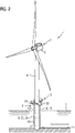
- FIG. 2 shows an offshore wind turbine 1 according to an embodiment of the invention comprising a flexible hose 26 hanging from a hose reel 27.
- the hose 26 can be raised above the water level 31 and lowered below the water level 31.
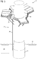
- Figure 3 shows a hose reel 27 mounted on a platform 32 of an offshore wind turbine 1.
- the hose reel 27 is attached to the platform 32, which simplifies the service works on the hose 26, such as the cleaning of the hose 26 and the fluid inlet 23 from marine growth.
- Figure 4 shows a hose 26 with a submergible pump 24 at the fluid inlet 23 located at an end of the hose 26.
- the input fluid 9 can be pumped from the water body to the electrolytic unit 3.
- Figure 5 shows a hose 26 with a submergible pump 24 and a weight 28 attached at the fluid inlet 23.
- the weight 28 stiffens the hose 26 so as to have a straight hose 26 and avoid that the hose 26 impacts the tower 4, the foundation 5 or other components.
- the weight 28 also stabilizes the hose 26 against waves, current or wind.
- Figure 6 shows a fluid supply assembly 21 with a guiding means 33 for guiding and supporting the hose 26, wherein the guiding means 33 comprises two bells 34 supported by beams 36.
- the bell 34 works as a funnel to easily catch the hanging hose 26 when being lowered from the raised position to the lowered position below the water level 31.
- the beam is attached to the foundation 5 for providing stability and support to the guiding means 33.
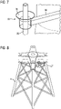
- Figure 7 shows a detailed view of a bell 34 supporting the hose 26.
- the shape of the funnel makes it easier to catch the hose 26 being lowered.
- Figure 8 shows the arrangement of the hose reel 27 on the foundation 5 of the offshore wind turbine 1. Depicted is a jacket frame foundation, but other foundations such as a monopile foundation, a tripod foundation, a gravity base foundation, a suction bucket formation, a tubular truss foundation or a tri-pile foundation can be used.
- Figure 9 shows a fluid supply assembly 21 with a guiding means 33 for guiding and supporting the hose 26, wherein the guiding means 33 comprises a bell 34 and a hollow casing 35 supported by beams 36.
- the hollow casing 35 is dimensioned in such a way as to allow the hose 26 to be raised and lowered within the hollow casing 35.
- the hollow casing 35 is like a guiding tunnel guiding the hose 26 from a raised position to a lowered position and vice versa.
- a scraper can be added to the hollow casing 35 to clean the hose 26 when it is being lowered or raised.
- Figure 10 shows a hose reel 27 rotatably attached to a hose reel mount 29, wherein the hose reel 27 can be manually rotated by means of a handle 38.
- the handle 38 is connected to a spool 37 configured as a rotatable cylinder. The rotation of the spool 37 allow to wind and unwind the hose 26.
- Figure 11 shows a hose reel 27 rotatably attached to a hose reel mount 29, wherein the hose reel 27 can be manually rotated by means of a handle 38 or automatically rotated by means of a motor 39. Both the motor 39 and the handle 38 are connected to a spool 37 configured as a rotatable cylinder. The rotation of the spool 37 allow to wind and unwind the hose 26.
Landscapes
- Engineering & Computer Science (AREA)
- Chemical & Material Sciences (AREA)
- Electrochemistry (AREA)
- Chemical Kinetics & Catalysis (AREA)
- Sustainable Energy (AREA)
- Combustion & Propulsion (AREA)
- Mechanical Engineering (AREA)
- General Engineering & Computer Science (AREA)
- Life Sciences & Earth Sciences (AREA)
- Sustainable Development (AREA)
- Materials Engineering (AREA)
- Metallurgy (AREA)
- Organic Chemistry (AREA)
- Power Engineering (AREA)
- Wind Motors (AREA)
Abstract
An offshore wind turbine (1) erected in a body of water comprising a generator (2), a foundation (5), a nacelle (6), a tower (4) having a first end mounted to the foundation (5) and a second end supporting the nacelle (6), an electrolytic unit (3) arranged above a water level (31) and electrically powered by the generator (2) to produce hydrogen (6) from an input fluid (9), in particular water, and a fluid supply assembly (21) for supplying the input fluid (9) to the electrolytic unit (3), wherein the fluid supply assembly (21) comprises a flexible hose (26) with a fluid inlet (23) configured to be submerged under the water level (31) and a hose reel (26) configured to be rotated for winding the hose (26) thereon.
Description
- The present invention relates to an offshore wind turbine with a fluid supply assembly. The present invention further relates to a method of supplying input fluid to an offshore wind turbine.
- Wind turbines are increasingly used for the generation of electrical energy. A wind turbine typically comprises a tower and a nacelle mounted on the tower, to which a hub is attached. A rotor is mounted at the hub and coupled to a generator. A plurality of blades extends from the rotor. The blades are oriented in such a way that wind passing over the blades turns the rotor, thereby driving the generator. Hence, the rotational energy of the blades is transferred to the generator, which then converts the mechanical energy into electricity and transfers the electricity to the electrical grid.
- Wind turbines are placed at locations providing high wind amounts. These locations can be remote onshore locations or offshore locations on the sea. For the transportation of the electrical energy, the power generated by the generator of the wind turbine travels to a transmission substation of the wind farm, where it is converted to high voltage, usually between 130-765kV, for long distance transmission on the transmission grid over power lines. The transmission grid connects the remote location of the wind farm to a transformer station of the electrical grid, which transforms the electricity to a voltage compatible with the electrical grid.
- A problem of remote wind farms is that the distance between the wind farm and the transformer station of the electrical grid needs to be bridged. Long power lines with very high installation costs are required.
- The current development of the technology of wind turbines tends to an increased size of wind turbines for harvesting more wind energy, with longer blades and higher towers. Due to the increasing size of wind turbines, more power is supplied to the grid which is to be transported from the wind farm to the nearest input point of the grid. Increasing the power transferred over the long-distance power lines results in higher requirements for the cables and higher costs.
- To reduce the amount of energy transferred by the power lines of the transmission grid or to avoid the use of long-distance power lines completely, an electrolytic unit can be installed in the vicinity of the wind turbine. A wind turbine comprising an electrolytic unit generates electrical power by means of the generator and hydrogen by means of the electrolytic unit driven by at least a part of the power of the wind turbine.
- Electrolytic units are power-to-gas units configured to produce hydrogen. Hence, the energy produced by the wind turbine may be used in an electrolysis process to generate hydrogen and oxygen. These gases can be used afterwards for the generation of electrical energy in fuel cells or to produce chemicals, such as ammonia or methane. The produced gases from the electrolytic unit can be transported by using a pipeline or by pressurizing the gas into a container, which is less expensive than transporting electricity directly over long-distance power lines.
- The use of electrolytic units in combination with wind turbines is known from the prior art, for example in the document
US 5,592,028 A , where a plurality of electrolysis cells are connected to a wind farm and produce hydrogen by means of the electricity produced by the generators of the wind turbines. Similarly, the documentWO 2020/095012 A1 describes an offshore wind turbine system for the large-scale production of hydrogen, which includes a floating tower structure with a desalination unit and an electrolysis unit. - In a wind farm with an electrolytic unit, hydrogen is produced with an input fluid. For example, for offshore wind farms, the input fluid is seawater, which is desalinated before entering the electrolytic device. Alternatively, the offshore wind farm might be located on a lake or any water body and the input fluid is water, which is usually filtered prior to entering the electrolytic device. A problem offshore wind turbines face is that the input fluid has to be supplied to the platform where the electrolytic unit is arranged, where the height difference between the water level and the platform has to be overcome. This is achieved by means of a fluid supply assembly. Traditional fluid supply assemblies comprise a hose hanging in the water with a submerged pump. The hose is designed to protect the pump and the pipeline from external forces from the wind and the waves.
- Hanging fluid supply assemblies have the risk of the hose colliding against the tower, thereby damaging itself and the tower due to strong winds. The hose is also exposed to harsh environmental conditions and has to overcome heights often over 20 meters above the water level, so a damage of the hanging fluid supply results in high costs of materials and working hours so as to replace damaged components.
- It is an object of the invention to provide an offshore wind turbine with a fluid supply assembly that overcomes the problems known form the prior art.
- This is achieved by an offshore wind turbine according to claim 1 and a method of supplying input fluid to an offshore wind turbine according to claim 15.
- According to the invention, an offshore wind turbine erected in a body of water comprises a generator, a foundation, a nacelle, a tower having a first end mounted to the foundation and a second end supporting the nacelle, an electrolytic unit arranged above a water level and electrically powered by the generator to produce hydrogen from an input fluid, in particular water, and a fluid supply assembly for supplying the input fluid to the electrolytic unit. The fluid supply assembly comprises a flexible hose with a fluid inlet configured to be submerged under the water level and a hose reel configured to be rotated for winding the hose thereon.
- The generator generates electric power and supplies the electrolytic unit with at least a part of the power generated, as both components are electrically coupled.
- Due to the fluctuation of the power generation, depending for example on weather conditions and wind levels, it is difficult to foresee the power output of an offshore wind turbine to the electricity grid or to an energy storage device. By using a part of the energy produced by the generator to produce hydrogen, the fluctuations can be mitigated. The hydrogen can be taken out of the wind turbine by a system outlet coupled to the output of the electrolytic unit.
- Hence, at least a part of the energy produced by the generator can be used to power an electrolytic unit, so that the electricity grid is not overloaded by peaks of power generation of the fluctuating power generation facility. Additionally, if a problem in the output to the electricity grid occurs, the power can be redirected completely to the electrolytic unit so that only hydrogen, is produced. The hydrogen produced is usually in a gaseous state, which can be compressed and/or mixed with other components to a liquid state which is easier to store and/or transport.
- The electrolytic unit can also be a mixed gas generator which performs electrolysis and generates other gases. For example, the electrolytic unit can perform electrolysis on water and carbon dioxide to generate a mixed gas made of hydrogen and carbon monoxide. Alternatively, hydrogen can be mixed with natural gas, which increases the hydrogen/carbon ratio of the hydrogen and gives it a flame speed up to eight times higher than compressed natural gas.
- The electrolytic unit is used to produce hydrogen from water. Hence, as the wind turbine is installed in the vicinity of water, i.e. a river or at the sea, the electrolytic unit can use this water as an input to the electrolytic unit to produce hydrogen and oxygen. It is however also possible to further process the hydrogen and get other compounds, such as methane or ammonia.
- The water is extracted by means of the fluid supply assembly. Hence, the fluid supply assembly supplies the input fluid from a fluid inlet configured to be arranged below a water level to the electrolytic unit arranged above the water level, for example by means of a pump configured to pump the input fluid from the body of water and through the fluid connection between the fluid inlet and the electrolytic unit.
- The hose of the fluid supply assembly is flexible to be able to wind the hose on the hose reel. Hence, by rotating the hose reel, the flexible hose can be lowered from a raised position to a lowered position or vice versa. The fluid supply assembly can comprise means to rotate the hose reel for winding the hose thereon and thereby changing from a lowered position of the hose to a raised position of the hose.
- The raised position can be a position in which the hose is completely rolled over the water level and the lowered position is a position in which the fluid inlet of the hose is submerged under the water level.
- In the lowered position, the hose can be hanging from the hose reel without any supporting or guiding means, i.e. it can be hanging free.
- The hose can be for example a hollow tube which can be reinforced for a better durability.
- According to a preferred embodiment of the invention, the offshore wind turbine further comprises a platform supporting at least a part of the electrolytic unit above the water level, wherein the hose reel is arranged at the platform.
- With the dedicated platform, the electrolytic unit can be more easily mounted than for example by installing the electrolytic unit on the nacelle and at least a part of the electrolytic unit can be kept above the water level.
- The platform provides for an open space where components such as the hose reel can be arranged. It is easily accessible by workers, hence simplifying maintenance works at the hose reel or the rotation of the hose reel if done manually. For example, the hose can be cleaned from marine growth much more easily if it is raised to the platform, as the hose reel is arranged at the platform.
- According to another preferred embodiment of the invention, the hose is coated or comprises a cover to protect the hose. For example, the hose can have a cover from polyethylene to protect the hose and the foundation wall or the tower wall in case of impacts.
- According to another preferred embodiment of the invention, the length of the hose is adjusted according to the water level. For example, the hose can be lowered below the low tide level to be all the time under the water level when the input fluid is needed. Alternatively, the hose can adjust according to the tidal range and the waves to be below the water level when the input fluid is needed and thereby having a minimal hose length, which is advantageous to prevent that the hose hits the foundation or the tower wall.
- According to another preferred embodiment of the invention, the offshore wind turbine comprises a transition piece between the foundation and the tower, wherein the hose reel is arranged at the transition piece.
- The transition piece is disposed on top of the foundation. A particularly preferred type of coupling is a transition piece disposed on top of a monopile, where the transition piece includes the platform disposed on an outer periphery of the transition piece.
- According to another preferred embodiment of the invention, the hose reel is arranged at the foundation. Preferably, the hose reel is arranged close to the water level, hence at the foundation, to have a shorter hose hanging from the hose reel. This is advantageous, as the hose's oscillations due to wind and waves can be controlled better the shorter the hose is, thereby avoiding that the hose hits the tower or the foundation wall.
- According to another preferred embodiment of the invention, the hose reel is arranged at the tower. Due to space reasons, it might be necessary to arrange the hose reel at the tower.
- According to another preferred embodiment of the invention, the hose is formed of a polymer material or an epoxy material with a supporting fiber reinforcement to avoid corrosion.
- According to another preferred embodiment of the invention, the hose is formed of glass fiber.
- According to another preferred embodiment of the invention, the hose reel comprises a spool and a handle to turn the spool.
- The spool may be a rotatable cylinder or core or drum which may be connected to the handle and which may rotate upon rotation of the handle. The handle may be a single-position non-folding handle; or may be a multi-position collapsible handle or crank which may be placed by the user in a lowered or folded position or in a raised or extended position, by utilizing a folding mechanism allowing the handle to fold or pivot.
- By means of the handle, the hose reel can be manually rotated from a lowered position to a raised position or vice versa. A rotation of the handle causes a rotation of the spool about a common axis of rotation, which is generally parallel to the surface on which the hose reel is arranged. Such rotation causes the winding of the flexible hose. The flexible hose may be detachably connected to the spool by using a hose connector or other connection mechanisms, for example, a clip, a screw, a pair of screws, a pressure-based connector, a male/female connector, a forcible insertion of the flexible hose into a corresponding hole or cavity within the spool or other suitable connection mechanisms.
- According to another preferred embodiment of the invention, a motor is operably coupled to the hose reel to turn it. Preferably, the motor is controlled automatically by a control unit to lower the hose when input fluid is needed and to raise the hose when no input fluid is needed. Advantageously, the hose reel comprises both a handle to turn the hose reel manually and a motor to turn to hose reel automatically. In case of failure of the motor, the hose reel can be turned manually with the handle.
- According to another preferred embodiment of the invention, the hose reel is rotatably attached to a hose reel mount. The hose reel mount is a structure used for mounting the hose reel to another component such as the tower, the foundation or the platform. It also gives structural stability to the hose reel.
- According to another preferred embodiment of the invention, the fluid supply assembly further comprises a submergible pump at or close to the fluid inlet.
- Hence, within the hose or at the end of the hose, a submergible pump is installed to pump the fluid to the electrolytic unit.
- According to another preferred embodiment of the invention, the pump is installed inside the hose, wherein the pump can be lifted through the hose for inspection and maintenance works. The pump can also be lowered through the hose. Additionally, the pump can also be raised to be above the water level to protect the pump against corrosion and the marine environment when it is not being used. This also limits the marine growth on the pump and on the hose.
- The pump can be raised also due to harsh weather conditions, i.e. due to a storm or the like to protect the pump.
- A crane can be installed to move the pump to a location where it can be serviced more easily.
- According to another preferred embodiment of the invention, the fluid supply assembly further comprises a weight attached at or close to the fluid inlet. The weight stiffens the hose so as to have a straight hose and avoid that the hose impacts the tower wall, the foundation wall or other components. The weight also stabilizes the hose against waves, current or wind. The weight added depends on the site conditions.
- According to another preferred embodiment of the invention, the fluid supply assembly further comprises a guiding means for guiding and supporting the hose. The guiding means are advantageous to keep the hose in position and avoid oscillations of the hose, which can result in impacts to the tower wall, the foundation wall or other components and in damage.
- According to another preferred embodiment of the invention, the guiding means comprises a bell supported by a beam through which the hose is guided. The bell works as a funnel to easily catch the hanging hose when being lowered from the raised position to the lowered position below the water level. The beam can be attached to the foundation, to the tower or to any other component for providing stability and support to the guiding means.
- According to another preferred embodiment of the invention, the guiding means comprises a hollow casing through which the hose is guided. Hence, the hose is contained in a hollow casing, for example a caisson, i.e. a watertight retaining structure.
- The hollow casing can be dimensioned in such a way as to allow the hose to be raised and lowered within the hollow casing. Hence, the hollow casing is like a guiding tunnel guiding the hose from a raised position to a lowered position and vice versa.
- According to another preferred embodiment of the invention, the hose is raised and lowered after a specific time or periodically for keeping the hollow casing clean. For example, the hose is moved up and down once a day to keep the hollow casing clean. The hose may also comprise a scraper to clear off any marine growth when lowered or raised in the hollow casing.
- According to another preferred embodiment of the invention, the fluid supply assembly comprises a filter for filtering the input fluid. Hence, particles and other substances in the water are filtered prior to entering the electrolytic unit.
- According to another preferred embodiment of the invention, the filter is installed inside the hose, wherein the filter can be lifted through the hose for cleaning, inspection and maintenance works.
- According to another preferred embodiment of the invention, the fluid inlet is arranged in the lowered position of the hose at a distance sufficiently removed from the ground level for avoiding the introduction of sand or other substances from the ground level into the fluid inlet. The ground level is the level below the body of water, for example the seabed level. This method reduces the costs of filtering, as less energy and maintenance of the filters is needed.
- According to another preferred embodiment of the invention, the fluid inlet is made from an antifouling material, such as copper, to avoid plant growth, in particular marine growth, on the fluid inlet. In particular, any inert material can be used as antifouling material to prevent the formation of plants on the fluid inlet, which obstructs the water flow.
- Yet another aspect of the invention relates to a method of supplying input fluid to an offshore wind turbine comprising the step of lowering the flexible hose from a raised position above the water level to a lowered position below the water level in particular by turning the hose reel, and suctioning input fluid through the fluid inlet for supplying the electrolytic unit with the input fluid.
- In order to facilitate the understanding of the characteristics of the invention and being an integral part of this specification, some drawing sheets are attached on which figures, with an illustrative but not limiting character, the following is represented:
-
Figure 1 shows a schematic view of an offshore wind turbine comprising a hose hanging from the electrolytic unit for the fluid supply. -
Figure 2 shows an offshore wind turbine according to an embodiment of the invention comprising a flexible hose hanging from a hose reel. -
Figure 3 shows a hose reel mounted on a platform of an offshore wind turbine. -
Figure 4 shows a hose with a submergible pump at the fluid inlet located at an end of the hose. -
Figure 5 shows a hose with a submergible pump and a weight attached at the fluid inlet. -
Figure 6 shows a fluid supply assembly with a guiding means for guiding and supporting the hose, wherein the guiding means comprises two bells supported by beams. -
Figure 7 shows a detailed view of a bell supporting the hose. -
Figure 8 shows the arrangement of the hose reel on the foundation of the offshore wind turbine. -
Figure 9 shows a fluid supply assembly with a guiding means for guiding and supporting the hose, wherein the guiding means comprises a bell and a hollow casing supported by beams. -
Figure 10 shows a hose reel rotatably attached to a hose reel mount, wherein the hose reel can be manually rotated by means of a handle. -
Figure 11 shows a hose reel rotatably attached to a hose reel mount, wherein the hose reel can be manually rotated by means of a handle or automatically rotated by means of a motor. -
Figure 1 shows a schematic view of an offshore wind turbine 1 comprising a hose hanging from theelectrolytic unit 3 for the fluid supply. - The offshore wind turbine 1 comprises a
tower 4 on top of which anacelle 6 is rotatably mounted. The offshore wind turbine 1 further comprises a hub which is connected to thenacelle 6. A plurality of blades is mounted on the hub. The hub is connected to agenerator 2 and is rotatably mounted about a rotor axis by means of a main bearing. The offshore wind turbine 1 further comprises aplatform 32 on which theelectrolytic unit 3 is arranged above thewater level 31. The offshore wind turbine 1 further comprises afoundation 5 on which thetower 4 is mounted. Thefoundation 5 is a monopile mounted to the floor of the body of water. - The power produced by the
generator 2 is completely transferred to theelectrolytic unit 3, but it would be also possible to connect the offshore wind turbine 1 to an electricity grid and transfer a part of the power produced by thegenerator 2 to the electricity grid. Theelectrolytic unit 3 comprises adesalination unit 11 and anelectrolytic device 12, as well as a fluid connection between thedesalination unit 11 and theelectrolytic device 12 through which desalinatedwater 14 is transported. Theelectrolytic device 12 and thedesalination unit 11 are both powered by thegenerator 2, which is connected to both devices by means of an electric connection 7. - The input fluid 9 for the
electrolytic unit 3 issaltwater 13 taken of the sea of the offshore wind turbine 1 by means of apump 24. Hence, thefluid supply assembly 21supplies saltwater 13 to theelectrolytic unit 3 by means of a hanginghose 26. Thehose 26 hangs from thedesalination unit 11 to the water body at the outer part of thefundament 5. Thesaltwater 13 enters thefluid supply assembly 21 through afluid inlet 23 and is transported through thehose 26, which creates a fluid connection 22 between thefluid inlet 23 and thedesalination unit 11 forming part of theelectrolytic unit 3. Thefluid inlet 23 and thepump 24 are submerged below thewater level 31 to suction thesaltwater 13. - The desalinated
water 14 is the input fluid 9 of theelectrolytic device 12. The electrolytic device has a hydrogen output 15 through which the hydrogen 8 generated is extracted. This hydrogen output 15 is connected to a hydrogen pipeline to transport the hydrogen 8 onshore. Alternatively, the hydrogen 8 could be filled in containers and transported onshore. -
Figure 2 shows an offshore wind turbine 1 according to an embodiment of the invention comprising aflexible hose 26 hanging from ahose reel 27. By means of thehose reel 27, thehose 26 can be raised above thewater level 31 and lowered below thewater level 31. -
Figure 3 shows ahose reel 27 mounted on aplatform 32 of an offshore wind turbine 1. Thehose reel 27 is attached to theplatform 32, which simplifies the service works on thehose 26, such as the cleaning of thehose 26 and thefluid inlet 23 from marine growth. -
Figure 4 shows ahose 26 with asubmergible pump 24 at thefluid inlet 23 located at an end of thehose 26. With thesubmergible pump 24, the input fluid 9 can be pumped from the water body to theelectrolytic unit 3. -
Figure 5 shows ahose 26 with asubmergible pump 24 and aweight 28 attached at thefluid inlet 23. Theweight 28 stiffens thehose 26 so as to have astraight hose 26 and avoid that thehose 26 impacts thetower 4, thefoundation 5 or other components. Theweight 28 also stabilizes thehose 26 against waves, current or wind. -
Figure 6 shows afluid supply assembly 21 with a guiding means 33 for guiding and supporting thehose 26, wherein the guiding means 33 comprises twobells 34 supported bybeams 36. Thebell 34 works as a funnel to easily catch the hanginghose 26 when being lowered from the raised position to the lowered position below thewater level 31. The beam is attached to thefoundation 5 for providing stability and support to the guiding means 33. -
Figure 7 shows a detailed view of abell 34 supporting thehose 26. The shape of the funnel makes it easier to catch thehose 26 being lowered. -
Figure 8 shows the arrangement of thehose reel 27 on thefoundation 5 of the offshore wind turbine 1. Depicted is a jacket frame foundation, but other foundations such as a monopile foundation, a tripod foundation, a gravity base foundation, a suction bucket formation, a tubular truss foundation or a tri-pile foundation can be used. -
Figure 9 shows afluid supply assembly 21 with a guiding means 33 for guiding and supporting thehose 26, wherein the guiding means 33 comprises abell 34 and ahollow casing 35 supported bybeams 36. Thehollow casing 35 is dimensioned in such a way as to allow thehose 26 to be raised and lowered within thehollow casing 35. Hence, thehollow casing 35 is like a guiding tunnel guiding thehose 26 from a raised position to a lowered position and vice versa. A scraper can be added to thehollow casing 35 to clean thehose 26 when it is being lowered or raised. -
Figure 10 shows ahose reel 27 rotatably attached to ahose reel mount 29, wherein thehose reel 27 can be manually rotated by means of ahandle 38. Thehandle 38 is connected to aspool 37 configured as a rotatable cylinder. The rotation of thespool 37 allow to wind and unwind thehose 26. -
Figure 11 shows ahose reel 27 rotatably attached to ahose reel mount 29, wherein thehose reel 27 can be manually rotated by means of ahandle 38 or automatically rotated by means of amotor 39. Both themotor 39 and thehandle 38 are connected to aspool 37 configured as a rotatable cylinder. The rotation of thespool 37 allow to wind and unwind thehose 26. -
- 1
- Offshore wind turbine
- 2
- Generator
- 3
- Electrolytic unit
- 4
- Tower
- 5
- Foundation
- 6
- Nacelle
- 7
- Electrical connection
- 8
- Hydrogen
- 9
- Input fluid
- 11
- Desalination unit
- 12
- Electrolytic device
- 13
- Saltwater
- 14
- Desalinated water
- 15
- Hydrogen output
- 21
- Fluid supply assembly
- 22
- Fluid connection
- 23
- Fluid inlet
- 24
- Pump
- 25
- Filter
- 26
- Hose
- 27
- Hose reel
- 28
- Weight
- 29
- Hose reel mount
- 31
- Water level
- 32
- Platform
- 33
- Guiding means
- 34
- Bell
- 35
- Hollow casing
- 36
- Beam
- 37
- Spool
- 38
- Handle
- 39
- Motor
Claims (15)
- An offshore wind turbine (1) erected in a body of water comprising
a generator (2),
a foundation (5),
a nacelle (6),
a tower (4) having a first end mounted to the foundation (5) and a second end supporting the nacelle (6),
an electrolytic unit (3) arranged above a water level (31) and electrically powered by the generator (2) to produce hydrogen (6) from an input fluid (9), in particular water, and a fluid supply assembly (21) for supplying the input fluid (9) to the electrolytic unit (3),
characterized in that the fluid supply assembly (21) comprises a flexible hose (26) with a fluid inlet (23) configured to be submerged under the water level (31) and a hose reel (26) configured to be rotated for winding the hose (26) thereon. - The offshore wind turbine (1) according to claim 1, characterized in that said offshore wind turbine (1) further comprises a platform (32) supporting at least a part of the electrolytic unit (3) above the water level (31), wherein the hose reel (27) is arranged at the platform (32).
- The offshore wind turbine (1) according to claim 1, characterized in that the hose reel (27) is arranged at the foundation (5).
- The offshore wind turbine (1) according to claim 1, characterized in that the hose reel (27) is arranged at the tower (4) .
- The offshore wind turbine (1) according to any of the preceding claims, characterized in that the hose reel (27) comprises a spool (37) and a handle (38) to turn the spool (37).
- The offshore wind turbine (1) according to any of the preceding claims, characterized in that a motor (39) is operably coupled to the hose reel (27) to turn it.
- The offshore wind turbine (1) according to any of the preceding claims, characterized in that the hose reel (27) is rotatably attached to a hose reel mount (29).
- The offshore wind turbine (1) according to any of the preceding claims, characterized in that the fluid supply assembly (21) further comprises a submergible pump (24) at or close to the fluid inlet (23).
- The offshore wind turbine (1) according to any of the preceding claims, characterized in that the fluid supply assembly (21) further comprises a weight (28) attached at or close to the fluid inlet (23).
- The offshore wind turbine (1) according to any of the preceding claims, characterized in that the fluid supply assembly (21) further comprises a guiding means (33) for guiding and supporting the hose (26).
- The offshore wind turbine (1) according to claim 10, characterized in that the guiding means (33) comprises a bell (34) supported by a beam (36) through which the hose (34) is guided.
- The offshore wind turbine (1) according to claim 10 or 11, characterized in that the guiding means (33) comprises a hollow casing (35) through which the hose (34) is guided.
- The offshore wind turbine (1) according to any of the preceding claims, characterized in that the fluid supply assembly (21) comprises a filter (25) for filtering the input fluid (9).
- The offshore wind turbine (1) according to any of the preceding claims, characterized in that the fluid inlet (23) is arranged in the lowered position of the hose (26) at a distance sufficiently removed from the ground level for avoiding the introduction of sand or other substances from the ground level into the fluid inlet (23).
- Method of supplying input fluid (9) to an offshore wind turbine (1) according to any of the preceding claims, the method comprising the steps of:- lowering the flexible hose (23) from a raised position above the water level (31) to a lowered position below the water level (31) in particular by turning the hose reel (27), and- suctioning input fluid (9) through the fluid inlet (23) for supplying the electrolytic unit (3) with the input fluid (9).
Priority Applications (1)
| Application Number | Priority Date | Filing Date | Title |
|---|---|---|---|
| EP21186356.8A EP4123171A1 (en) | 2021-07-19 | 2021-07-19 | Offshore wind turbine with a fluid supply assembly comprising a hose and a hose reel |
Applications Claiming Priority (1)
| Application Number | Priority Date | Filing Date | Title |
|---|---|---|---|
| EP21186356.8A EP4123171A1 (en) | 2021-07-19 | 2021-07-19 | Offshore wind turbine with a fluid supply assembly comprising a hose and a hose reel |
Publications (1)
| Publication Number | Publication Date |
|---|---|
| EP4123171A1 true EP4123171A1 (en) | 2023-01-25 |
Family
ID=76971702
Family Applications (1)
| Application Number | Title | Priority Date | Filing Date |
|---|---|---|---|
| EP21186356.8A Withdrawn EP4123171A1 (en) | 2021-07-19 | 2021-07-19 | Offshore wind turbine with a fluid supply assembly comprising a hose and a hose reel |
Country Status (1)
| Country | Link |
|---|---|
| EP (1) | EP4123171A1 (en) |
Cited By (7)
| Publication number | Priority date | Publication date | Assignee | Title |
|---|---|---|---|---|
| CN116517777A (en) * | 2023-06-15 | 2023-08-01 | 中国三峡新能源(集团)股份有限公司 | Wind power generation device and offshore wind power generation system |
| GB2618416A (en) * | 2022-05-04 | 2023-11-08 | Subsea 7 Norway As | Delivering power to offshore vessels |
| GB2618415A (en) * | 2022-05-04 | 2023-11-08 | Subsea 7 Norway As | Delivering power to offshore vessels |
| EP4446579A1 (en) * | 2023-04-14 | 2024-10-16 | Siemens Gamesa Renewable Energy A/S | Submersible water pump system for a wind turbine |
| EP4477876A1 (en) * | 2023-06-13 | 2024-12-18 | Siemens Gamesa Renewable Energy A/S | Method for installing a wind turbine system and wind turbine system |
| CN119508147A (en) * | 2024-10-30 | 2025-02-25 | 中国电建集团贵阳勘测设计研究院有限公司 | A deep sea floating wind power-temperature difference energy comprehensive utilization system |
| EP4545784A1 (en) * | 2023-10-26 | 2025-04-30 | Siemens Gamesa Renewable Energy A/S | Method for storing at least one pipe of a stationary offshore device and stationary offshore device |
Citations (5)
| Publication number | Priority date | Publication date | Assignee | Title |
|---|---|---|---|---|
| US5592028A (en) | 1992-01-31 | 1997-01-07 | Pritchard; Declan N. | Wind farm generation scheme utilizing electrolysis to create gaseous fuel for a constant output generator |
| US20090313896A1 (en) * | 2008-06-20 | 2009-12-24 | Cameron Glidewell | Hydrogen generation and distribution system |
| KR20130035499A (en) * | 2011-09-30 | 2013-04-09 | 삼성중공업 주식회사 | Marine structure |
| WO2020095012A1 (en) | 2018-11-09 | 2020-05-14 | Environmental Resources Management Ltd. | Offshore wind turbine system for the large scale production of hydrogen |
| WO2021098929A1 (en) * | 2019-11-22 | 2021-05-27 | Vestas Wind Systems A/S | A wind turbine |
-
2021
- 2021-07-19 EP EP21186356.8A patent/EP4123171A1/en not_active Withdrawn
Patent Citations (5)
| Publication number | Priority date | Publication date | Assignee | Title |
|---|---|---|---|---|
| US5592028A (en) | 1992-01-31 | 1997-01-07 | Pritchard; Declan N. | Wind farm generation scheme utilizing electrolysis to create gaseous fuel for a constant output generator |
| US20090313896A1 (en) * | 2008-06-20 | 2009-12-24 | Cameron Glidewell | Hydrogen generation and distribution system |
| KR20130035499A (en) * | 2011-09-30 | 2013-04-09 | 삼성중공업 주식회사 | Marine structure |
| WO2020095012A1 (en) | 2018-11-09 | 2020-05-14 | Environmental Resources Management Ltd. | Offshore wind turbine system for the large scale production of hydrogen |
| WO2021098929A1 (en) * | 2019-11-22 | 2021-05-27 | Vestas Wind Systems A/S | A wind turbine |
Cited By (9)
| Publication number | Priority date | Publication date | Assignee | Title |
|---|---|---|---|---|
| GB2618416A (en) * | 2022-05-04 | 2023-11-08 | Subsea 7 Norway As | Delivering power to offshore vessels |
| GB2618415A (en) * | 2022-05-04 | 2023-11-08 | Subsea 7 Norway As | Delivering power to offshore vessels |
| GB2618415B (en) * | 2022-05-04 | 2024-10-02 | Subsea 7 Norway As | Delivering power to offshore vessels |
| GB2618416B (en) * | 2022-05-04 | 2024-10-02 | Subsea 7 Norway As | Delivering power to offshore vessels |
| EP4446579A1 (en) * | 2023-04-14 | 2024-10-16 | Siemens Gamesa Renewable Energy A/S | Submersible water pump system for a wind turbine |
| EP4477876A1 (en) * | 2023-06-13 | 2024-12-18 | Siemens Gamesa Renewable Energy A/S | Method for installing a wind turbine system and wind turbine system |
| CN116517777A (en) * | 2023-06-15 | 2023-08-01 | 中国三峡新能源(集团)股份有限公司 | Wind power generation device and offshore wind power generation system |
| EP4545784A1 (en) * | 2023-10-26 | 2025-04-30 | Siemens Gamesa Renewable Energy A/S | Method for storing at least one pipe of a stationary offshore device and stationary offshore device |
| CN119508147A (en) * | 2024-10-30 | 2025-02-25 | 中国电建集团贵阳勘测设计研究院有限公司 | A deep sea floating wind power-temperature difference energy comprehensive utilization system |
Similar Documents
| Publication | Publication Date | Title |
|---|---|---|
| US11953027B2 (en) | Offshore wind turbine with a fluid supply assembly | |
| US11926910B2 (en) | Offshore wind turbine with a fluid supply assembly comprising a cleaning unit | |
| EP2604501B1 (en) | System of anchoring and mooring of floating wind turbine towers and corresponding methods for towing and erecting thereof | |
| US8966899B2 (en) | System and method for storing energy | |
| US20240384701A1 (en) | Wind turbine with electrolytic unit housed inside the tower | |
| JP4279148B2 (en) | Wind turbine | |
| US20240426277A1 (en) | Wind turbine with a fire extinguishing system | |
| CN101611226A (en) | Energy extraction method and apparatus | |
| CN1491318A (en) | Device for producing energy from currents in a body of water, foundation, and method for installing the device | |
| GB2578451A (en) | Generating electrical power underwater | |
| US8884458B2 (en) | Floating wind farm | |
| US10648447B2 (en) | Mechanical system for extracting energy from marine waves | |
| CN110171534B (en) | Polymer ocean buoy | |
| EP4283119B1 (en) | Hydrogen manifold for wind turbines | |
| Li et al. | Offshore wind turbines and their installation | |
| JP7569003B2 (en) | Pillar-shaped float, pillar-shaped float erection system, and pillar-shaped float erection method | |
| WO2025217717A1 (en) | Nearshore monopile mounted wave energy collector |
Legal Events
| Date | Code | Title | Description |
|---|---|---|---|
| PUAI | Public reference made under article 153(3) epc to a published international application that has entered the european phase |
Free format text: ORIGINAL CODE: 0009012 |
|
| STAA | Information on the status of an ep patent application or granted ep patent |
Free format text: STATUS: THE APPLICATION HAS BEEN PUBLISHED |
|
| AK | Designated contracting states |
Kind code of ref document: A1 Designated state(s): AL AT BE BG CH CY CZ DE DK EE ES FI FR GB GR HR HU IE IS IT LI LT LU LV MC MK MT NL NO PL PT RO RS SE SI SK SM TR |
|
| STAA | Information on the status of an ep patent application or granted ep patent |
Free format text: STATUS: THE APPLICATION IS DEEMED TO BE WITHDRAWN |
|
| 18D | Application deemed to be withdrawn |
Effective date: 20230726 |