EP4123055A1 - Photochemical reaction system and photochemical reaction method - Google Patents
Photochemical reaction system and photochemical reaction method Download PDFInfo
- Publication number
- EP4123055A1 EP4123055A1 EP22159737.0A EP22159737A EP4123055A1 EP 4123055 A1 EP4123055 A1 EP 4123055A1 EP 22159737 A EP22159737 A EP 22159737A EP 4123055 A1 EP4123055 A1 EP 4123055A1
- Authority
- EP
- European Patent Office
- Prior art keywords
- generating cell
- electrode
- hydrogen
- oxygen
- temperature difference
- Prior art date
- Legal status (The legal status is an assumption and is not a legal conclusion. Google has not performed a legal analysis and makes no representation as to the accuracy of the status listed.)
- Granted
Links
Images



Classifications
-
- C—CHEMISTRY; METALLURGY
- C25—ELECTROLYTIC OR ELECTROPHORETIC PROCESSES; APPARATUS THEREFOR
- C25B—ELECTROLYTIC OR ELECTROPHORETIC PROCESSES FOR THE PRODUCTION OF COMPOUNDS OR NON-METALS; APPARATUS THEREFOR
- C25B15/00—Operating or servicing cells
- C25B15/08—Supplying or removing reactants or electrolytes; Regeneration of electrolytes
-
- C—CHEMISTRY; METALLURGY
- C25—ELECTROLYTIC OR ELECTROPHORETIC PROCESSES; APPARATUS THEREFOR
- C25B—ELECTROLYTIC OR ELECTROPHORETIC PROCESSES FOR THE PRODUCTION OF COMPOUNDS OR NON-METALS; APPARATUS THEREFOR
- C25B1/00—Electrolytic production of inorganic compounds or non-metals
- C25B1/01—Products
- C25B1/02—Hydrogen or oxygen
- C25B1/04—Hydrogen or oxygen by electrolysis of water
-
- C—CHEMISTRY; METALLURGY
- C25—ELECTROLYTIC OR ELECTROPHORETIC PROCESSES; APPARATUS THEREFOR
- C25B—ELECTROLYTIC OR ELECTROPHORETIC PROCESSES FOR THE PRODUCTION OF COMPOUNDS OR NON-METALS; APPARATUS THEREFOR
- C25B1/00—Electrolytic production of inorganic compounds or non-metals
- C25B1/50—Processes
-
- C—CHEMISTRY; METALLURGY
- C25—ELECTROLYTIC OR ELECTROPHORETIC PROCESSES; APPARATUS THEREFOR
- C25B—ELECTROLYTIC OR ELECTROPHORETIC PROCESSES FOR THE PRODUCTION OF COMPOUNDS OR NON-METALS; APPARATUS THEREFOR
- C25B1/00—Electrolytic production of inorganic compounds or non-metals
- C25B1/50—Processes
- C25B1/55—Photoelectrolysis
-
- C—CHEMISTRY; METALLURGY
- C25—ELECTROLYTIC OR ELECTROPHORETIC PROCESSES; APPARATUS THEREFOR
- C25B—ELECTROLYTIC OR ELECTROPHORETIC PROCESSES FOR THE PRODUCTION OF COMPOUNDS OR NON-METALS; APPARATUS THEREFOR
- C25B11/00—Electrodes; Manufacture thereof not otherwise provided for
- C25B11/04—Electrodes; Manufacture thereof not otherwise provided for characterised by the material
- C25B11/042—Electrodes formed of a single material
- C25B11/049—Photocatalysts
-
- C—CHEMISTRY; METALLURGY
- C25—ELECTROLYTIC OR ELECTROPHORETIC PROCESSES; APPARATUS THEREFOR
- C25B—ELECTROLYTIC OR ELECTROPHORETIC PROCESSES FOR THE PRODUCTION OF COMPOUNDS OR NON-METALS; APPARATUS THEREFOR
- C25B15/00—Operating or servicing cells
- C25B15/02—Process control or regulation
-
- C—CHEMISTRY; METALLURGY
- C25—ELECTROLYTIC OR ELECTROPHORETIC PROCESSES; APPARATUS THEREFOR
- C25B—ELECTROLYTIC OR ELECTROPHORETIC PROCESSES FOR THE PRODUCTION OF COMPOUNDS OR NON-METALS; APPARATUS THEREFOR
- C25B15/00—Operating or servicing cells
- C25B15/02—Process control or regulation
- C25B15/023—Measuring, analysing or testing during electrolytic production
- C25B15/025—Measuring, analysing or testing during electrolytic production of electrolyte parameters
- C25B15/027—Temperature
-
- C—CHEMISTRY; METALLURGY
- C25—ELECTROLYTIC OR ELECTROPHORETIC PROCESSES; APPARATUS THEREFOR
- C25B—ELECTROLYTIC OR ELECTROPHORETIC PROCESSES FOR THE PRODUCTION OF COMPOUNDS OR NON-METALS; APPARATUS THEREFOR
- C25B15/00—Operating or servicing cells
- C25B15/08—Supplying or removing reactants or electrolytes; Regeneration of electrolytes
- C25B15/085—Removing impurities
-
- C—CHEMISTRY; METALLURGY
- C25—ELECTROLYTIC OR ELECTROPHORETIC PROCESSES; APPARATUS THEREFOR
- C25B—ELECTROLYTIC OR ELECTROPHORETIC PROCESSES FOR THE PRODUCTION OF COMPOUNDS OR NON-METALS; APPARATUS THEREFOR
- C25B3/00—Electrolytic production of organic compounds
- C25B3/20—Processes
- C25B3/21—Photoelectrolysis
-
- C—CHEMISTRY; METALLURGY
- C25—ELECTROLYTIC OR ELECTROPHORETIC PROCESSES; APPARATUS THEREFOR
- C25B—ELECTROLYTIC OR ELECTROPHORETIC PROCESSES FOR THE PRODUCTION OF COMPOUNDS OR NON-METALS; APPARATUS THEREFOR
- C25B9/00—Cells or assemblies of cells; Constructional parts of cells; Assemblies of constructional parts, e.g. electrode-diaphragm assemblies; Process-related cell features
- C25B9/17—Cells comprising dimensionally-stable non-movable electrodes; Assemblies of constructional parts thereof
- C25B9/19—Cells comprising dimensionally-stable non-movable electrodes; Assemblies of constructional parts thereof with diaphragms
-
- Y—GENERAL TAGGING OF NEW TECHNOLOGICAL DEVELOPMENTS; GENERAL TAGGING OF CROSS-SECTIONAL TECHNOLOGIES SPANNING OVER SEVERAL SECTIONS OF THE IPC; TECHNICAL SUBJECTS COVERED BY FORMER USPC CROSS-REFERENCE ART COLLECTIONS [XRACs] AND DIGESTS
- Y02—TECHNOLOGIES OR APPLICATIONS FOR MITIGATION OR ADAPTATION AGAINST CLIMATE CHANGE
- Y02E—REDUCTION OF GREENHOUSE GAS [GHG] EMISSIONS, RELATED TO ENERGY GENERATION, TRANSMISSION OR DISTRIBUTION
- Y02E60/00—Enabling technologies; Technologies with a potential or indirect contribution to GHG emissions mitigation
- Y02E60/30—Hydrogen technology
- Y02E60/36—Hydrogen production from non-carbon containing sources, e.g. by water electrolysis
Definitions
- the present invention relates to photochemical reaction systems and methods for photolyzing water to generate hydrogen gas and oxygen gas.
- Patent literature 1 has disclosed a technology for separately generating hydrogen and oxygen by giving and receiving electrons between a conductive wire and a redox pair in a two-chamber cell type hydrogen generating cell that is divided by a diaphragm.
- Patent literature 2 relates to a Z-scheme type visible light active photocatalyst-based method using the Fe3+/Fe2+ redox, and describes that the difference in adsorption amount suppresses the reverse reaction and that it is effective under the pH2.4 acidic condition.
- Patent literature 3 describes the complete water decomposition that utilizes visible light usable under the alkaline condition using the iodine compound (IO3-/I-) redox.
- the present invention provides a photochemical reaction system and method capable of recovering the efficiency of the hydrogen and oxygen generating reaction without loading additional redox compounds and replacing electrolytic solutions.
- the present invention provides a photochemical reaction system that includes a hydrogen generating cell containing a hydrogen generating type photocatalyst, an aqueous medium including a redox compound, and an electrolytic solution; and/or an oxygen generating cell containing an oxygen generating type photocatalyst, an aqueous medium including a redox compound, and an electrolytic solution, wherein the photochemical reaction system further includes a redox compound concentration polarization elimination part for eliminating the concentration polarization of the redox compound generated as a result of generating hydrogen gas from the hydrogen generating cell by irradiating the hydrogen generating cell with light and the concentration polarization of the redox compound generated as a result of generating oxygen gas from the oxygen generating cell by irradiating the oxygen generating cell with light.
- the present invention provides a photochemical reaction system that includes a hydrogen generating cell containing a hydrogen generating type photocatalyst, an aqueous medium including a redox compound, an electrolytic solution, and a first electrode; an oxygen generating cell containing an oxygen generating type photocatalyst, an aqueous medium including a redox compound, an electrolytic solution, and a second electrode; and/or an ion-permeable ion-exchange membrane for separating the hydrogen generating cell and the oxygen generating cell, wherein the photochemical reaction system further includes a redox compound concentration polarization elimination part for eliminating the concentration polarization of the redox compound in the hydrogen generating cell generated as a result of generating hydrogen gas from the hydrogen generating cell by irradiating the hydrogen generating cell with light and the concentration polarization of the redox compound in the oxygen generating cell generated as a result of generating oxygen gas from the oxygen generating cell by ir
- the present invention provides a photochemical reaction method that generates hydrogen gas from a hydrogen generating cell containing a hydrogen generating type photocatalyst, an aqueous medium including a redox compound, and/or an electrolytic solution by irradiating the hydrogen generating cell with light, and generates oxygen gas from an oxygen generating cell containing an oxygen generating type photocatalyst, an aqueous medium including a redox compound, and an electrolytic solution by irradiating the oxygen generating cell with light.
- temperature difference is generated between a hydrogen generating cell side first electrode and an oxygen generating cell side second electrode to thereby cause temperature difference power generation to occur between the first electrode and the second electrode.
- the photochemical reaction system for generating hydrogen and oxygen by utilizing visible light is capable of eliminating the concentration polarization of the redox compound that causes reverse reaction, by means of the temperature difference. As a result, it is possible to recover the efficiency of hydrogen and oxygen generating reaction without loading additional redox compounds and replacing electrolytic solutions, thereby increasing the operation rate of the photochemical reaction system.
- the present invention relates to a Z-scheme type artificial photosynthesis system and provides a hydrogen generating cell and a hydrogen generating cell control system capable of eliminating the concentration polarization of the redox compound that causes reverse reaction, by means of temperature difference in the hydrogen generating cell for generating hydrogen and oxygen utilizing visible light. As a result, it is possible to increase the efficiency of generating hydrogen and oxygen, thereby increasing the operation rate of the system.
- the present invention provides a hydrogen generating cell and a hydrogen generating cell control system that are characterized in that the hydrogen generating cell for generating hydrogen utilizing visible light includes a hydrogen generating type photoelectrode, an oxygen generating type photoelectrode, and an aqueous medium including a redox compound (mediator) that is a redox ion, and that a plurality of paired electrodes for applying temperature difference are disposed in the aqueous medium.
- the hydrogen generating cell for generating hydrogen utilizing visible light includes a hydrogen generating type photoelectrode, an oxygen generating type photoelectrode, and an aqueous medium including a redox compound (mediator) that is a redox ion, and that a plurality of paired electrodes for applying temperature difference are disposed in the aqueous medium.
- the hydrogen generating cell for generating hydrogen utilizing visible light includes a hydrogen generating type photoelectrode, an oxygen generating type photoelectrode, and an a
- the present invention relates to a photochemical reaction system and method for eliminating the concentration polarization by means of operation control to apply temperature difference during night-time with no sunlight irradiation. As a result, it is possible to recover the efficiency of hydrogen and oxygen generating reaction without loading additional redox compounds or replacing electrolytic solutions, thereby enabling longterm operation.
- the present invention relates to a hydrogen generating cell and a hydrogen generating cell control system that are characterized in that a switch for turning ON/OFF the current in a plurality of electrodes and a switching part for switching the switch according to the presence/absence of incident visible light are provided.
- the present invention provides a method of producing hydrogen and oxygen using a Z-scheme type water decomposition system by visible light that includes a hydrogen generating type photoelectrode, an oxygen generating type photoelectrode, an aqueous medium, and a redox compound functioning as a mediator, wherein temperature difference is applied in a reactor.
- the Z-scheme type water decomposition system by visible light has a structure that a pair of conductive electrodes connected by a conductive wire are disposed near the hydrogen generating type photoelectrode and near the oxygen generating type photoelectrode in the reactor so as to apply temperature difference between the paired electrodes in the reactor by applying high temperature to one electrode and low temperature to the other electrode.
- the Z-scheme type water decomposition system by visible light is so designed that when the redox compound is an N-type (thermoelectromotive force ⁇ >0), high temperature will be applied to the vicinity of the hydrogen generating type photoelectrode and low temperature will be applied to the vicinity of the oxygen generating type photoelectrode so as to apply temperature difference; consequently, the vicinity of the hydrogen generating electrode becomes [Ox]>[Red] and the oxygen generating electrode side becomes [Red]>[Ox], thereby inhibiting the reverse reaction in each photoelectrode.
- N-type thermoelectromotive force ⁇ >0
- the Z-scheme type water decomposition system by visible light is characterized in that when the redox compound is a P type (thermoelectromotive force ⁇ ⁇ 0), in case that low temperature will be applied to the vicinity of the hydrogen generating type photoelectrode and high temperature will be applied to the vicinity of the oxygen generating type photoelectrode so as to apply temperature difference; consequently, the vicinity of the hydrogen generating electrode becomes [Ox]>[Red] and the oxygen generating electrode side becomes [Red]>[Ox], thereby inhibiting the reverse reaction in each photoelectrode.
- the redox compound is a P type (thermoelectromotive force ⁇ ⁇ 0)
- the vicinity of the hydrogen generating electrode becomes [Ox]>[Red]
- the oxygen generating electrode side becomes [Red]>[Ox], thereby inhibiting the reverse reaction in each photoelectrode.
- the Z-scheme type water decomposition system by visible light is characterized in that the reactor is provided with an ion-selective permeable diaphragm (positive-ion permeation membrane or negative-ion permeation membrane), which allows only ions with an opposite sign of the electrical charge of the redox pair to permeate.
- ion-selective permeable diaphragm positive-ion permeation membrane or negative-ion permeation membrane
- Fig. 1 shows the structure of a photochemical reaction system 100 as an example of the Z-scheme type water decomposition system by visible light according to this example.
- the photochemical reaction system 100 includes a hydrogen and oxygen production part 110 for generating hydrogen and oxygen by photochemical reaction using water as raw material, a hydrogen production and efficiency recovery control system 120 for controlling the production of hydrogen and oxygen in the hydrogen and oxygen production part 110, a temperature difference application mechanism part 130 for controlling the temperature of the hydrogen and oxygen production part 110 so as to eliminate the concentration difference of the redox compound, and a switch 140 for turning ON/OFF the electrical circuit of the hydrogen and oxygen production part 110.
- the hydrogen and oxygen production part 110 includes a photochemical reaction apparatus with a temperature difference application mechanism 111, wherein water 112 introduced to the inside of the photochemical reaction apparatus with a temperature difference application mechanism 111 is irradiated with sunlight 113 to generate a photochemical reaction, thereby generating oxygen gas (O 2 ) 114 and hydrogen gas (H 2 ) 115.
- the hydrogen production and efficiency recovery control system 120 includes an illuminance and weather information acquisition part 121, a hydrogen production volume and STH efficiency calculation part 122, an oxygen production volume and STO efficiency calculation part 123, a voltage and current measurement (monitor) part 124, a temperature difference application part 125, a liquid replacement instruction display part 126, and a control part 127.
- the illuminance and weather information acquisition part 121 acquires information about the illuminance of sunlight 113 entering the photochemical reaction apparatus with a temperature difference application mechanism 111 and about the weather of the area where the photochemical reaction apparatus with a temperature difference application mechanism 111 is installed.
- the hydrogen production volume and STH efficiency calculation part 122 acquires information about the volume of hydrogen gas 115 generated by the photochemical reaction apparatus with a temperature difference application mechanism 111
- the oxygen production volume and STO efficiency calculation part 123 acquires information about the volume of oxygen gas 114 generated by the photochemical reaction apparatus with a temperature difference application mechanism 111.
- the voltage and current measurement (monitor) part 124 measures the current and voltage flowing between electrodes, described later, of the photochemical reaction apparatus with a temperature difference application mechanism 111.
- the temperature difference application part 125 heats up or cools down the heat source mounted to the photochemical reaction apparatus with a temperature difference application mechanism 111.
- the liquid replacement instruction display part 126 indicates the time for replacing the redox compound supplied to the photochemical reaction apparatus with a temperature difference application mechanism 111, and the control part 127 controls the entire photochemical reaction system 100 including the hydrogen production and efficiency recovery control system 120.
- the temperature difference application mechanism part 130 for controlling the temperature of the hydrogen and oxygen production part 110 to eliminate the concentration difference of the redox compound includes a temperature difference application apparatus 131 for applying temperature difference between an oxygen generating cell and a hydrogen generating cell, described later, of the photochemical reaction apparatus with a temperature difference application mechanism 111, and a voltage measuring apparatus 132 for measuring the voltage between electrodes, described later, of the photochemical reaction apparatus with a temperature difference application mechanism 111.
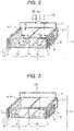
- Fig. 2 shows the state of the photochemical reaction apparatus with a temperature difference application mechanism 111 in the daytime, where incident sunlight decomposes water, thereby generating hydrogen and oxygen.
- Fig. 3 shows the state of the photochemical reaction apparatus with a temperature difference application mechanism 111 in the night-time, where sunlight is not shining and the concentration polarization of the redox compound is being eliminated.
- 1 denotes an oxygen generating cell
- 2 denotes a hydrogen generating cell
- 3 denotes an electrode
- 4 denotes an electrolytic solution supplied to the inside of the oxygen generating cell 1 and the hydrogen generating cell
- 5 denotes a redox compound supplied to the inside of the oxygen generating cell 1 and the hydrogen generating cell
- 7a denotes an ion-selective permeable diaphragm (ion-exchange membrane) formed by a positive-ion-exchange membrane or a negative-ion-exchange membrane
- 8a denotes a visible-light responding oxygen generating photocatalyst
- 9a denotes a visible-light responding hydrogen generating photocatalyst.
- the ion-selective permeable diaphragm 7a is an ion-exchange membrane that does not allow the redox compound 5 to permeate but allows the counterion to permeate.
- an ion-selective permeable diaphragm 7a as a diaphragm between the oxygen generating cell 1 and the hydrogen generating cell 2, it is possible to separately generate oxygen and hydrogen in the oxygen generating cell 1 and the hydrogen generating cell 2.
- Oxygen generated in the oxygen generating cell 1 and hydrogen generated in the hydrogen generating cell 2 are separately recovered by a recovery apparatus, not shown.
- a low-temperature-side heat source 11 and a circulating water pipe 13 for circulating cooling water in the low-temperature-side heat source 11 are buried in the area outside the oxygen generating cell 1. Also, a high-temperature-side heat source 10 and a circulating water pipe 12 for circulating hot water in the high-temperature-side heat source 10 are buried in the area outside the hydrogen generating cell 2.
- oxygen generating cell 1 side electrode 3 and the hydrogen generating cell 2 side electrode 3 are connected by a conductive wire 6 connected to a switch 140.
- oxidation reaction by the redox compound 5 occurs near the surface of the visible-light responding hydrogen generating photocatalyst 9a in the hydrogen generating cell 2, thereby generating hydrogen H 2 .
- concentration of oxidants increases near the surface of the visible-light responding hydrogen generating photocatalyst 9a in the hydrogen generating cell 2.
- the switch 140 is closed to electrically connect the oxygen generating cell 1 side electrode 3 and the hydrogen generating cell 2 side electrode 3 as shown in Fig. 3 .
- the hydrogen generating cell 2 side electrode 3 is heated by circulating hot water in the high-temperature-side heat source 10 through the circulating water pipe 12, and the oxygen generating cell 1 side electrode 3 is cooled by circulating cooling water in the low-temperature-side heat source 11 through the circulating water pipe 13.
- thermochemical battery In this state, based on the principle of thermochemical battery, redox pairs permeate the ion-selective permeable diaphragm 7a, causing the temperature difference between the oxygen generating cell 1 side electrode 3 and the hydrogen generating cell 2 side electrode 3, and move around in the electrolytic solution 4 between those electrodes, thereby generating a thermoelectromotive force. Consequently, the switch 140 closes and electric power is continuously generated among the oxygen generating cell 1 and the hydrogen generating cell 2 via the oxygen generating cell 1 side electrode 3 and the hydrogen generating cell 2 side electrode 3 that are electrically connected.
- Fig. 4 With reference to Fig. 4 , an explanation will be given about the generation of oxygen and hydrogen by means of sunlight irradiation and the state of oxidation reaction and reduction reaction caused as a result of heating the hydrogen generating cell 2 side electrode 3 and cooling the oxygen generating cell 1 side electrode 3, which are stated above.
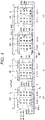
- Fig. 4(a) and Fig. 4(b ) correspond to the state shown in Fig. 2 and show the state with sunlight irradiation.
- Fig. 4(c) and Fig. 4(d) correspond to the state shown in Fig. 3 and show the state in which the high-temperature-side heat source 10 and the low-temperature-side heat source 11 are operating in the night-time with no sunlight irradiation.
- Fig. 4(a) shows the state immediately after the start of sunlight irradiation in the daytime. In this state, the switch 140 is open (OFF). In both the oxygen generating cell 1 and the hydrogen generating cell 2, the ratio of oxidants ([Ox]) 401 to reductants ([Red]) 402 (redox concentration ratio), expressed by [Ox]/[Red], is 1.
- Fig. 4(b) shows the state when many hours have passed after irradiation of sunlight started in the daytime.
- Reduction reaction progresses in the oxygen generating cell 1 to generate oxygen, and the percentage of reductants ([Red]) 402 increases and the percentage of oxidants ([Ox]) 401 decreases near the visible-light responding oxygen generating photocatalyst 8a.
- the ratio of oxidants ([Ox]) 401 to reductants ([Red]) 402, expressed by [Ox]/[Red] is sufficiently smaller than 1.
- oxidation reaction progresses in the hydrogen generating cell 2 thereby generating hydrogen, and the percentage of oxidants ([Ox]) 401 increases and the percentage of reductants ([Red]) 402 decreases near the visible-light responding hydrogen generating photocatalyst 9a.
- the ratio of oxidants ([Ox]) 401 to reductants ([Red]) 402, expressed by [Ox]/[Red] is sufficiently larger than 1, indicating the progress of polarization of redox concentration.
- Fig. 4(c) shows the initial state in the night-time with no sunlight irradiation.
- this state by closing (turning ON) the switch 140, the oxygen generating cell 1 side electrode 3 and the hydrogen generating cell 2 side electrode 3 are electrically connected by a conductive wire 6 as shown in Fig. 3 .
- Fig. 4(c) shows the state shortly after the high-temperature-side heat source 10 and the low-temperature-side heat source 11 started operating.
- this state based on the principle of thermochemical battery, redox pairs permeate the ion-selective permeable diaphragm 7a, causing the temperature difference between the oxygen generating cell 1 side electrode 3 and the hydrogen generating cell 2 side electrode 3, and move around in the electrolytic solution 4 between those electrodes, thereby generating a thermoelectromotive force and continuously generating electric power.
- the percentage of oxidants ([Ox]) 401 increases and the percentage of reductants ([Red]) 402 decreases near the visible-light responding oxygen generating photocatalyst 8a due to the oxidation reaction when compared with the state shown in Fig. 4(b) .
- the ratio of oxidants ([Ox]) 401 to reductants ([Red]) 402, expressed by [Ox]/[Red] is smaller than 1 but larger than the value shown in Fig. 4(b) .
- Fig. 4(d) shows the state some time after the state shown in Fig. 4(c) in the night-time.
- the oxidation reaction in the oxygen generating cell 1 and the reduction reaction in the hydrogen generating cell 2 have sufficiently progressed, causing the electromotive force to decrease, and the voltage between the oxygen generating cell 1 side electrode 3 and the hydrogen generating cell 2 side electrode 3 becomes almost zero.
- the ratio of oxidants ([Ox]) 401 to reductants ([Red]) 402, expressed by [Ox]/[Red] is 1, which indicates that the polarization of redox concentration has been eliminated.
- the heating and cooling means disposed outside the oxygen generating cell 1 and the hydrogen generating cell 2 apply temperature difference between the electrode installed in the oxygen generating cell 1 (visible-light responding oxygen generating photocatalyst 8a) and the electrode installed in the hydrogen generating cell 2 (visible-light responding hydrogen generating photocatalyst 9a) in the night-time when hydrogen gas is not generated due to the reduction of illuminance so that the polarization of redox concentration can be eliminated in each cell.
- the efficiency of hydrogen generating reaction during the daytime is recovered, thereby enabling the system to be repetitively used.
- thermoelectromotive force ⁇ is generated based on the principle of thermochemical battery.
- the voltage (equilibrium potential E) between the oxygen generating cell 1 side electrode 3 and the hydrogen generating cell 2 side electrode 3 is measured by the voltage measuring apparatus 132.
- E T 2 E T 2 0 + RT 2 nF ln 0 x T 2 Red T 2
- E T 1 ⁇ E T 2 E T 1 0 ⁇ E T 2 0 + R nF T 1 ⁇ T 2 ln 0 x T 1 Red T 1 Red T 2 0 x T 2
- ⁇ E ⁇ T + 2.303 ⁇ T n log 0 x T 1 Red T 1 Red T 2 0 x T 2
- Very little electric power generated by the temperature difference power generation can be used for charging storage battery so as to be used for the bias voltage assist and the power to auxiliary devices.
- thermoelectromotive force ⁇ that varies according to redox species will determine which cell to set at high temperature, the oxygen generating cell 1 or the hydrogen generating cell 2.
- type N in order to inhibit the reverse reaction in the hydrogen generating cell 2 by converting excessive oxidants ([Ox]) 401 to reductants ([Red]) 402 to eliminate the concentration difference and make the concentration ratio close to 1, the hydrogen generating cell 2 is set at a high temperature as described in Fig. 3 .
- the oxygen generating cell 1 in order to inhibit the reverse reaction in the oxygen generating cell 1 by converting excessive reductants ([Red]) 402 to oxidants ([Ox]) 401 to eliminate the concentration difference and make the concentration ratio close to 1, the oxygen generating cell 1 is set at a high temperature as opposed to the description provided in Fig. 3 .
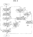
- the light entering the photochemical reaction apparatus with a temperature difference application mechanism 111 is measured by means of an illuminance meter, not shown. Then, the information about illuminance and weather that has been stored in the illuminance and weather information acquisition part 121 of the hydrogen production and efficiency recovery control system 120 is input to the control part 127 (S501).
- control part 127 information about the volume of hydrogen produced in the hydrogen and oxygen production part 110 is input into the control part 127 (S502).
- the volume of hydrogen produced in the hydrogen and oxygen production part 110 was detected by a hydrogen detector, not shown, and has been stored in the hydrogen production volume and STH efficiency calculation part 122.
- control part 127 determines whether hydrogen is being generated from the hydrogen and oxygen production part 110 (S503).
- the volume of hydrogen to be generated in the hydrogen and oxygen production part 110 is estimated based on the illuminance information input in S501, and in comparison with the volume of hydrogen produced in the hydrogen and oxygen production part 110 input in S502, it is determined whether the volume of hydrogen estimated from the illuminance is being generated in the hydrogen and oxygen production part 110 (S504).
- the control part 127 instructs the switch 140 to close, as described in Fig. 3 , to electrically connect the oxygen generating cell 1 side electrode 3 and the hydrogen generating cell 2 side electrode 3. Furthermore, hot water is circulated through the circulating water pipe 12 in the high-temperature-side heat source 10 to heat up the hydrogen generating cell 2, and cooling water is circulated through the circulating water pipe 13 in the low-temperature-side heat source 11 to cool down the oxygen generating cell 1. By doing so, temperature of the hydrogen generating cell 2 side electrode 3 increases and temperature of the oxygen generating cell 1 side electrode 3 decreases.
- Information about the potential difference, measured by the voltage measuring apparatus 132, is stored in the voltage and current measurement (monitor) part 124.
- ⁇ E obtained by the above (Equation 1) through (Equation 5) or (Equation 6) corresponds to the potential difference stored in the voltage and current measurement (monitor) part 124.
- the control part 127 determines whether the potential difference, expressed by ⁇ E, between the oxygen generating cell 1 side electrode 3 and the hydrogen generating cell 2 side electrode 3 has reached the predetermined value (S507).
- control part 127 instructs the switch 140 to open so as to electrically disconnect the oxygen generating cell 1 side electrode 3 and the hydrogen generating cell 2 side electrode 3, and the process will return to S501.
- the liquid replacement instruction display part 126 of the hydrogen production and efficiency recovery control system 120 prompts the replacement of the electrolytic solution 4 and the redox compound 5 contained in the oxygen generating cell 1 and the hydrogen generating cell 2, and the procedures will be terminated.
- Fig. 2 and Fig. 3 show the example of the structure using the visible-light responding oxygen generating photocatalyst 8a and the visible-light responding hydrogen generating photocatalyst 9a, each formed into a sheet.
- these photocatalysts may be substituted by the visible-light responding oxygen generating photocatalyst particles 8b and the visible-light responding hydrogen generating photocatalyst particles 9b that will be described later in example 2.
- Fig. 2 and Fig. 3 show the example of the structure in which the oxygen generating cell 1 and the hydrogen generating cell 2 are separated only by the ion-selective permeable diaphragm 7a.
- the structure may be designed so that the oxygen generating cell 1 and the hydrogen generating cell 2 are separated by combining the ion-selective permeable diaphragm 7a and other material so as to reduce the area of the ion-selective permeable diaphragm 7a.
- the method of producing hydrogen and oxygen by means of water decomposition by sunlight includes means for eliminating the concentration polarization of the redox compound. This makes it possible to prevent the stagnation of water decomposition due to the disproportion of concentration of the redox compound near the electrodes as a result of continuing the water decomposition, thereby allowing the redox compound to be used continuously for comparatively long time without replacing it.
- hydrogen and oxygen can be produced repetitively every day by means of the sunlight water-splitting.
- Fig. 2 and Fig. 3 show the structure where the oxygen generating cell 1 and the hydrogen generating cell 2 are separated by the ion-selective permeable diaphragm 7a.
- the oxygen generating cell 1 and the hydrogen generating cell 2 may be separated by a separation barrier using an insulator made of resin etc. without using the ion-selective permeable diaphragm 7a.
- the structure of the photochemical reaction apparatus with a temperature difference application mechanism 111-1 corresponds to the photochemical reaction apparatus with a temperature difference application mechanism 111, described in example 1 with reference to Fig. 2 and Fig. 3 .
- the photochemical reaction apparatus with a temperature difference application mechanism 111-1 shown in Fig. 6 and Fig. 7 , has a different structure where the ion-selective permeable diaphragm 7a is substituted by a divider 7b, the visible-light responding oxygen generating photocatalyst 8a is substituted by visible-light responding oxygen generating photocatalyst particles 8b, and the visible-light responding hydrogen generating photocatalyst 9a is substituted by visible-light responding hydrogen generating photocatalyst particles 9b.
- the visible-light responding oxygen generating photocatalyst particles 8b may be substituted by the visible-light responding oxygen generating photocatalyst 8a formed into a sheet, as explained in example 1, and the visible-light responding hydrogen generating photocatalyst particles 9b may also be substituted by the visible-light responding hydrogen generating photocatalyst 9a.
- the oxygen generating cell 1 and the hydrogen generating cell 2 are completely separated by the ion-selective permeable diaphragm 7a, constituting two chambers.
- the oxygen generating cell 1-1 and the hydrogen generating cell 2-1 are not completely separated, and these cells substantially constitute one chamber.
- the oxygen generating cell 1-1 and the hydrogen generating cell 2-1 are separated by a divider 7b that is lower than the ion-selective permeable diaphragm 7a in example 1.
- the divider 7b has the role of dividing the visible-light responding oxygen generating photocatalyst particles 8b in the oxygen generating cell 1-1 and the visible-light responding hydrogen generating photocatalyst particles 9b in the hydrogen generating cell 2-1 so that they do not mix.
- oxygen gas generated in the oxygen generating cell 1-1 and hydrogen gas generated in the hydrogen generating cell 2-1 as a result of irradiation of sunlight 113 are extracted as a mixture.
- a gas separation means not shown, for separating a hydrogen gas and an oxygen gas (for example, hydrogen separation membrane), it is possible to separately recover the oxygen gas and the hydrogen gas.
- the oxygen generating cell 1-1 generates the oxidation reaction, thereby decreasing the percentage of reductants and increasing the percentage of oxidants, and thus the percentage of oxidants in the oxygen generating cell 1-1 that has been reduced due to the irradiation of sunlight 113 increases.
- the method of producing hydrogen and oxygen by water decomposition by sunlight includes means for eliminating the concentration polarization of the redox compound, which makes it possible to prevent the stagnation of water decomposition due to the disproportion of concentration of the redox compound near the electrodes as a result of continuing the water decomposition, thereby allowing the redox compound to be used continuously for comparatively long time without replacing it.
- hydrogen and oxygen can be produced repetitively every day by means of the water decomposition by sunlight.
- the structure, shown in Fig. 8 corresponds to the photochemical reaction apparatus with a temperature difference application mechanism 111, explained in example 1 with reference to Fig. 2 . Differences from the structure shown example 1 are the arrangement of the visible-light responding oxygen generating photocatalyst and the visible-light responding hydrogen generating photocatalyst, and the incident direction of the sunlight entering the oxygen generating cell and the hydrogen generating cell.
- the electrolytic solution and the redox compound used are the same as those used in example 1.
- 801 denotes an oxygen generating cell
- 802 denotes a hydrogen generating cell
- 803 denotes a separation barrier
- 804 denotes an electrolytic solution supplied to the inside of the oxygen generating cell 801 and the hydrogen generating cell 802
- 805 denotes a redox compound supplied to the inside of the oxygen generating cell 801 and the hydrogen generating cell 802
- 807 denotes an ion-selective permeable diaphragm formed by a positive-ion-exchange membrane or a negative-ion-exchange membrane
- 808 denotes a visible-light responding oxygen generating photocatalyst
- 809 denotes a visible-light responding hydrogen generating photocatalyst.
- 810 denotes a high-temperature-side heat source in which a circulating water pipe (not shown) for circulating hot water is buried.
- 811 denotes a low-temperature-side heat source in which a circulating water pipe (not shown) for circulating cooling water is buried.
- 813 denotes an oxygen generating cell side electrode made of transparent conductive material.
- 814 denotes a hydrogen generating cell side electrode made of transparent conductive material.
- 840 denotes a switch, and 806 denotes an electric wire that connects the oxygen generating cell side electrode 813 and the hydrogen generating cell side electrode 814 via the switch 840.
- the ion-selective permeable diaphragm 807 is an ion-exchange membrane which does not allow the redox compound 805 to permeate but allows the counterion to permeate.
- the oxygen gas generated in the oxygen generating cell 801 and the hydrogen gas generated in the hydrogen generating cell 802 are separately recovered by a recovery apparatus, not shown.
- the high-temperature-side heat source 810 and the low-temperature-side heat source 811 are at room temperature.
- the switch 840 is closed to electrically connect the oxygen generating cell side electrode 813 and the hydrogen generating cell side electrode 823, and the hydrogen generating cell 802 is heated by circulating hot water in the high-temperature-side heat source 810, and the oxygen generating cell 801 is cooled by circulating cooling water in the low-temperature-side heat source 811.
- the method of producing hydrogen and oxygen by water decomposition by sunlight includes means for eliminating the concentration polarization of the redox compound, which makes it possible to prevent the stagnation of water-splitting due to the disproportion of concentration of the redox compound near the electrodes as a result of continuing the water decomposition, thereby allowing the redox compound to be used continuously for comparatively long time without replacing it.
- hydrogen and oxygen can be produced repetitively every day by means of the water decomposition by sunlight.
- Fig. 8 shows the structure designed such that the oxygen generating cell 801 and the hydrogen generating cell 802 are separated by the separation barrier 803 and the ion-selective permeable diaphragm 807.
- the oxygen generating cell 801 and the hydrogen generating cell 802 may be separated only by the separation barrier 803 without using the ion-selective permeable diaphragm 807. By doing so, it is possible to replace half of the liquid in the oxygen generating cell 801 and half of the liquid in the hydrogen generating cell 802 in which concentration polarization of the redox compound has progressed as a result of continuing water decomposition.
Landscapes
- Chemical & Material Sciences (AREA)
- Engineering & Computer Science (AREA)
- Organic Chemistry (AREA)
- Metallurgy (AREA)
- Electrochemistry (AREA)
- Materials Engineering (AREA)
- Chemical Kinetics & Catalysis (AREA)
- Inorganic Chemistry (AREA)
- Automation & Control Theory (AREA)
- Analytical Chemistry (AREA)
- Electrolytic Production Of Non-Metals, Compounds, Apparatuses Therefor (AREA)
- Hybrid Cells (AREA)
- Treatment Of Water By Oxidation Or Reduction (AREA)
- Oxygen, Ozone, And Oxides In General (AREA)
- Catalysts (AREA)
Abstract
Description
- The present invention relates to photochemical reaction systems and methods for photolyzing water to generate hydrogen gas and oxygen gas.
- As an energy conversion technology utilizing the energy of sunlight, there is a need for practical application of hydrogen and oxygen production technology by means of water decomposition reaction using a photocatalyst. It is necessary to utilize visible light to achieve the practical efficiency of energy conversion, and development of visible light responding type photocatalysis is underway. As a complete water decomposition technology using visible light, a two-step excitation (Z-scheme) method that combines two types of optical semiconductors (hydrogen generation side and oxygen generation side) and a mediator (redox based) has been reported.
- Regarding the redox of the Z-scheme type water decomposition by visible light, the following
patent literature 1 to 3 is available. -
Patent literature 1 has disclosed a technology for separately generating hydrogen and oxygen by giving and receiving electrons between a conductive wire and a redox pair in a two-chamber cell type hydrogen generating cell that is divided by a diaphragm. -
Patent literature 2 relates to a Z-scheme type visible light active photocatalyst-based method using the Fe3+/Fe2+ redox, and describes that the difference in adsorption amount suppresses the reverse reaction and that it is effective under the pH2.4 acidic condition. -
Patent literature 3 describes the complete water decomposition that utilizes visible light usable under the alkaline condition using the iodine compound (IO3-/I-) redox. -
- Patent literature 1:
JP-A-2006-89336 - Patent literature 2:
JP-A-2005-199187 - Patent literature 3:
JP-A-2002-255502 - In the technology for separately generating hydrogen and oxygen, disclosed in
patent literature 1, the hydrogen generating reaction depends on [Red]/[Ox] of the redox pair and the redox pair becomes disproportionate. This will easily cause reverse reaction, thereby inhibiting the efficient hydrogen generating reaction. - As mentioned above, in the Z-scheme type water decomposition by visible light using a redox compound, as the concentration polarization of the initially loaded redox pair increases, reverse reaction progresses, which may cause hydrogen and oxygen generating reaction to stop. However, this problem is not mentioned in both
patent literature 2 andpatent literature 3. - To solve the above problems of the conventional technologies, the present invention provides a photochemical reaction system and method capable of recovering the efficiency of the hydrogen and oxygen generating reaction without loading additional redox compounds and replacing electrolytic solutions.
- To solve the above-mentioned problems, the present invention provides a photochemical reaction system that includes a hydrogen generating cell containing a hydrogen generating type photocatalyst, an aqueous medium including a redox compound, and an electrolytic solution; and/or an oxygen generating cell containing an oxygen generating type photocatalyst, an aqueous medium including a redox compound, and an electrolytic solution, wherein the photochemical reaction system further includes a redox compound concentration polarization elimination part for eliminating the concentration polarization of the redox compound generated as a result of generating hydrogen gas from the hydrogen generating cell by irradiating the hydrogen generating cell with light and the concentration polarization of the redox compound generated as a result of generating oxygen gas from the oxygen generating cell by irradiating the oxygen generating cell with light.
- Furthermore, to solve the above-mentioned problems, the present invention provides a photochemical reaction system that includes a hydrogen generating cell containing a hydrogen generating type photocatalyst, an aqueous medium including a redox compound, an electrolytic solution, and a first electrode; an oxygen generating cell containing an oxygen generating type photocatalyst, an aqueous medium including a redox compound, an electrolytic solution, and a second electrode; and/or an ion-permeable ion-exchange membrane for separating the hydrogen generating cell and the oxygen generating cell, wherein the photochemical reaction system further includes a redox compound concentration polarization elimination part for eliminating the concentration polarization of the redox compound in the hydrogen generating cell generated as a result of generating hydrogen gas from the hydrogen generating cell by irradiating the hydrogen generating cell with light and the concentration polarization of the redox compound in the oxygen generating cell generated as a result of generating oxygen gas from the oxygen generating cell by irradiating the oxygen generating cell with light. The redox compound concentration polarization elimination part eliminates the above generated concentration polarization of the redox compound by performing temperature difference power generation between the hydrogen generating cell and the oxygen generating cell.
- Moreover, to solve the above-mentioned problems, the present invention provides a photochemical reaction method that generates hydrogen gas from a hydrogen generating cell containing a hydrogen generating type photocatalyst, an aqueous medium including a redox compound, and/or an electrolytic solution by irradiating the hydrogen generating cell with light, and generates oxygen gas from an oxygen generating cell containing an oxygen generating type photocatalyst, an aqueous medium including a redox compound, and an electrolytic solution by irradiating the oxygen generating cell with light. In this method, temperature difference is generated between a hydrogen generating cell side first electrode and an oxygen generating cell side second electrode to thereby cause temperature difference power generation to occur between the first electrode and the second electrode. By doing so, eliminating of the concentration polarization of the redox compound generated as a result of generating hydrogen gas from the hydrogen generating cell by irradiating the hydrogen generating cell with light and the concentration polarization of the redox compound generated as a result of generating oxygen gas from the oxygen generating cell by irradiating the oxygen generating cell with light is performed.
- According to the present invention, the photochemical reaction system for generating hydrogen and oxygen by utilizing visible light is capable of eliminating the concentration polarization of the redox compound that causes reverse reaction, by means of the temperature difference. As a result, it is possible to recover the efficiency of hydrogen and oxygen generating reaction without loading additional redox compounds and replacing electrolytic solutions, thereby increasing the operation rate of the photochemical reaction system.
-
-
Fig. 1 is a block diagram showing the schematic structure of a photochemical reaction system according to example 1 of the present invention. -
Fig. 2 is a perspective view showing the structure of the hydrogen and oxygen production part, which is producing hydrogen and oxygen, in the photochemical reaction system according to example 1 of the present invention. -
Fig. 3 is a perspective view showing the structure of the hydrogen and oxygen production part, which is performing temperature difference power generation, in the photochemical reaction system according to example 1 of the present invention. -
Fig. 4 shows a cross-sectional view of the oxygen generating cell and the hydrogen generating cell presented to explain the state of producing hydrogen and oxygen and the state of performing temperature difference power generation in the photochemical reaction system according to example 1 of the present invention1. -
Fig. 5 is a flow chart showing the processing flow of the hydrogen and oxygen production and the temperature difference power generation in the photochemical reaction system according to example 1 of the present invention. -
Fig. 6 is a perspective view showing the structure of the hydrogen and oxygen production part, which is producing hydrogen and oxygen, in a photochemical reaction system according to example 2 of the present invention. -
Fig. 7 is a perspective view showing the structure of the hydrogen and oxygen production part, which is performing temperature difference power generation, in the photochemical reaction system according to example 2 of the present invention. -
Fig. 8 is a perspective view showing the structure of the hydrogen and oxygen production part, which is producing hydrogen and oxygen, in a photochemical reaction system according to example 3 of the present invention. - The present invention relates to a Z-scheme type artificial photosynthesis system and provides a hydrogen generating cell and a hydrogen generating cell control system capable of eliminating the concentration polarization of the redox compound that causes reverse reaction, by means of temperature difference in the hydrogen generating cell for generating hydrogen and oxygen utilizing visible light. As a result, it is possible to increase the efficiency of generating hydrogen and oxygen, thereby increasing the operation rate of the system.
- That is, the present invention provides a hydrogen generating cell and a hydrogen generating cell control system that are characterized in that the hydrogen generating cell for generating hydrogen utilizing visible light includes a hydrogen generating type photoelectrode, an oxygen generating type photoelectrode, and an aqueous medium including a redox compound (mediator) that is a redox ion, and that a plurality of paired electrodes for applying temperature difference are disposed in the aqueous medium.
- Also, the present invention relates to a photochemical reaction system and method for eliminating the concentration polarization by means of operation control to apply temperature difference during night-time with no sunlight irradiation. As a result, it is possible to recover the efficiency of hydrogen and oxygen generating reaction without loading additional redox compounds or replacing electrolytic solutions, thereby enabling longterm operation.
- Furthermore, the present invention relates to a hydrogen generating cell and a hydrogen generating cell control system that are characterized in that a switch for turning ON/OFF the current in a plurality of electrodes and a switching part for switching the switch according to the presence/absence of incident visible light are provided.
- Moreover, the present invention provides a method of producing hydrogen and oxygen using a Z-scheme type water decomposition system by visible light that includes a hydrogen generating type photoelectrode, an oxygen generating type photoelectrode, an aqueous medium, and a redox compound functioning as a mediator, wherein temperature difference is applied in a reactor.
- The Z-scheme type water decomposition system by visible light has a structure that a pair of conductive electrodes connected by a conductive wire are disposed near the hydrogen generating type photoelectrode and near the oxygen generating type photoelectrode in the reactor so as to apply temperature difference between the paired electrodes in the reactor by applying high temperature to one electrode and low temperature to the other electrode.
- Furthermore, the Z-scheme type water decomposition system by visible light is so designed that when the redox compound is an N-type (thermoelectromotive force α>0), high temperature will be applied to the vicinity of the hydrogen generating type photoelectrode and low temperature will be applied to the vicinity of the oxygen generating type photoelectrode so as to apply temperature difference; consequently, the vicinity of the hydrogen generating electrode becomes [Ox]>[Red] and the oxygen generating electrode side becomes [Red]>[Ox], thereby inhibiting the reverse reaction in each photoelectrode.
- Furthermore, the Z-scheme type water decomposition system by visible light is characterized in that when the redox compound is a P type (thermoelectromotive force α<0), in case that low temperature will be applied to the vicinity of the hydrogen generating type photoelectrode and high temperature will be applied to the vicinity of the oxygen generating type photoelectrode so as to apply temperature difference; consequently, the vicinity of the hydrogen generating electrode becomes [Ox]>[Red] and the oxygen generating electrode side becomes [Red]>[Ox], thereby inhibiting the reverse reaction in each photoelectrode.
- Moreover, the Z-scheme type water decomposition system by visible light is characterized in that the reactor is provided with an ion-selective permeable diaphragm (positive-ion permeation membrane or negative-ion permeation membrane), which allows only ions with an opposite sign of the electrical charge of the redox pair to permeate.
- Hereinafter, embodiments of the present invention will be described in detail with reference to the drawings. The same sign is provided for the portion having the same function in the drawings used for describing the embodiments, and repetitive description will be omitted.
- The present invention is not limited to the description of the embodiments provided below. Various modifications are possible without departing from the technical concept of the invention as is understood by those skilled in the art.
-
Fig. 1 shows the structure of aphotochemical reaction system 100 as an example of the Z-scheme type water decomposition system by visible light according to this example. - The
photochemical reaction system 100 according to this example includes a hydrogen andoxygen production part 110 for generating hydrogen and oxygen by photochemical reaction using water as raw material, a hydrogen production and efficiencyrecovery control system 120 for controlling the production of hydrogen and oxygen in the hydrogen andoxygen production part 110, a temperature differenceapplication mechanism part 130 for controlling the temperature of the hydrogen andoxygen production part 110 so as to eliminate the concentration difference of the redox compound, and aswitch 140 for turning ON/OFF the electrical circuit of the hydrogen andoxygen production part 110. - The hydrogen and
oxygen production part 110 includes a photochemical reaction apparatus with a temperaturedifference application mechanism 111, whereinwater 112 introduced to the inside of the photochemical reaction apparatus with a temperaturedifference application mechanism 111 is irradiated withsunlight 113 to generate a photochemical reaction, thereby generating oxygen gas (O2) 114 and hydrogen gas (H2) 115. - The hydrogen production and efficiency
recovery control system 120 includes an illuminance and weatherinformation acquisition part 121, a hydrogen production volume and STHefficiency calculation part 122, an oxygen production volume and STOefficiency calculation part 123, a voltage and current measurement (monitor)part 124, a temperaturedifference application part 125, a liquid replacementinstruction display part 126, and acontrol part 127. - The illuminance and weather
information acquisition part 121 acquires information about the illuminance ofsunlight 113 entering the photochemical reaction apparatus with a temperaturedifference application mechanism 111 and about the weather of the area where the photochemical reaction apparatus with a temperaturedifference application mechanism 111 is installed. - The hydrogen production volume and STH
efficiency calculation part 122 acquires information about the volume ofhydrogen gas 115 generated by the photochemical reaction apparatus with a temperaturedifference application mechanism 111, and the oxygen production volume and STOefficiency calculation part 123 acquires information about the volume ofoxygen gas 114 generated by the photochemical reaction apparatus with a temperaturedifference application mechanism 111. - The voltage and current measurement (monitor)
part 124 measures the current and voltage flowing between electrodes, described later, of the photochemical reaction apparatus with a temperaturedifference application mechanism 111. The temperaturedifference application part 125 heats up or cools down the heat source mounted to the photochemical reaction apparatus with a temperaturedifference application mechanism 111. - The liquid replacement
instruction display part 126 indicates the time for replacing the redox compound supplied to the photochemical reaction apparatus with a temperaturedifference application mechanism 111, and thecontrol part 127 controls the entirephotochemical reaction system 100 including the hydrogen production and efficiencyrecovery control system 120. - The temperature difference
application mechanism part 130 for controlling the temperature of the hydrogen andoxygen production part 110 to eliminate the concentration difference of the redox compound includes a temperaturedifference application apparatus 131 for applying temperature difference between an oxygen generating cell and a hydrogen generating cell, described later, of the photochemical reaction apparatus with a temperaturedifference application mechanism 111, and avoltage measuring apparatus 132 for measuring the voltage between electrodes, described later, of the photochemical reaction apparatus with a temperaturedifference application mechanism 111. - The detailed structure of the photochemical reaction apparatus with a temperature
difference application mechanism 111 in the hydrogen andoxygen production part 110 according to this example will be described with reference toFig. 2 and Fig. 3 . -
Fig. 2 shows the state of the photochemical reaction apparatus with a temperaturedifference application mechanism 111 in the daytime, where incident sunlight decomposes water, thereby generating hydrogen and oxygen. -
Fig. 3 shows the state of the photochemical reaction apparatus with a temperaturedifference application mechanism 111 in the night-time, where sunlight is not shining and the concentration polarization of the redox compound is being eliminated. - In the structure shown in
Fig. 2 andFig. 3 ,1 denotes an oxygen generating cell, 2 denotes a hydrogen generating cell, 3 denotes an electrode, 4 denotes an electrolytic solution supplied to the inside of theoxygen generating cell 1 and thehydrogen generating cell oxygen generating cell 1 and thehydrogen generating cell - The ion-selective
permeable diaphragm 7a is an ion-exchange membrane that does not allow theredox compound 5 to permeate but allows the counterion to permeate. By using such an ion-selectivepermeable diaphragm 7a as a diaphragm between theoxygen generating cell 1 and thehydrogen generating cell 2, it is possible to separately generate oxygen and hydrogen in theoxygen generating cell 1 and thehydrogen generating cell 2. - As for the
redox compound 5, it is desirable that the redox level be between 0 and +1.23V (vs NHE, pH=0). For example, it is possible to adopt an Fe3+/Fe2+ type redox or an IO3-/I- type redox. - Oxygen generated in the
oxygen generating cell 1 and hydrogen generated in thehydrogen generating cell 2 are separately recovered by a recovery apparatus, not shown. - A low-temperature-
side heat source 11 and a circulatingwater pipe 13 for circulating cooling water in the low-temperature-side heat source 11 are buried in the area outside theoxygen generating cell 1. Also, a high-temperature-side heat source 10 and a circulatingwater pipe 12 for circulating hot water in the high-temperature-side heat source 10 are buried in the area outside thehydrogen generating cell 2. - Furthermore, the
oxygen generating cell 1side electrode 3 and thehydrogen generating cell 2side electrode 3 are connected by aconductive wire 6 connected to aswitch 140. - In the above structure, if
sunlight 113, denoted by hv, shines while theswitch 140 is open as shown inFig. 2 , reduction reaction by theredox compound 5 occurs near the surface of the visible-light respondingoxygen generating photocatalyst 8a in theoxygen generating cell 1, thereby generating oxygen O2. As the reduction reaction progresses, concentration of reductants increases in theoxygen generating cell 1. - On the other hand, oxidation reaction by the
redox compound 5 occurs near the surface of the visible-light respondinghydrogen generating photocatalyst 9a in thehydrogen generating cell 2, thereby generating hydrogen H2. As the oxidation reaction progresses, concentration of oxidants increases near the surface of the visible-light respondinghydrogen generating photocatalyst 9a in thehydrogen generating cell 2. - At this time, neither hot water nor cooling water circulates through the circulating
water pipes side heat source 10 and the low-temperature-side heat source 11 are at room temperature. - On the other hand, for example, in the night-time when
sunlight 113 is not shining, theswitch 140 is closed to electrically connect theoxygen generating cell 1side electrode 3 and thehydrogen generating cell 2side electrode 3 as shown inFig. 3 . In this state, thehydrogen generating cell 2side electrode 3 is heated by circulating hot water in the high-temperature-side heat source 10 through the circulatingwater pipe 12, and theoxygen generating cell 1side electrode 3 is cooled by circulating cooling water in the low-temperature-side heat source 11 through the circulatingwater pipe 13. - By doing so, temperature of the
hydrogen generating cell 2side electrode 3 increases. In this state, reduction reaction occurs in thehydrogen generating cell 2 and the oxidant is converted to the reductant. Accordingly, the redox ratio in thehydrogen generating cell 2 that has been reduced due to the irradiation of thesunlight 113 increases. - On the other hand, temperature of the
oxygen generating cell 1side electrode 3 drops. In this state, oxidation reaction occurs in theoxygen generating cell 1 and the percentage of reductants decreases and the percentage of oxidants increases. - In this state, based on the principle of thermochemical battery, redox pairs permeate the ion-selective
permeable diaphragm 7a, causing the temperature difference between theoxygen generating cell 1side electrode 3 and thehydrogen generating cell 2side electrode 3, and move around in theelectrolytic solution 4 between those electrodes, thereby generating a thermoelectromotive force. Consequently, theswitch 140 closes and electric power is continuously generated among theoxygen generating cell 1 and thehydrogen generating cell 2 via theoxygen generating cell 1side electrode 3 and thehydrogen generating cell 2side electrode 3 that are electrically connected. - With reference to
Fig. 4 , an explanation will be given about the generation of oxygen and hydrogen by means of sunlight irradiation and the state of oxidation reaction and reduction reaction caused as a result of heating thehydrogen generating cell 2side electrode 3 and cooling theoxygen generating cell 1side electrode 3, which are stated above.Fig. 4(a) and Fig. 4(b ) correspond to the state shown inFig. 2 and show the state with sunlight irradiation.Fig. 4(c) and Fig. 4(d) correspond to the state shown inFig. 3 and show the state in which the high-temperature-side heat source 10 and the low-temperature-side heat source 11 are operating in the night-time with no sunlight irradiation. -
Fig. 4(a) shows the state immediately after the start of sunlight irradiation in the daytime. In this state, theswitch 140 is open (OFF). In both theoxygen generating cell 1 and thehydrogen generating cell 2, the ratio of oxidants ([Ox]) 401 to reductants ([Red]) 402 (redox concentration ratio), expressed by [Ox]/[Red], is 1. -
Fig. 4(b) shows the state when many hours have passed after irradiation of sunlight started in the daytime. Reduction reaction progresses in theoxygen generating cell 1 to generate oxygen, and the percentage of reductants ([Red]) 402 increases and the percentage of oxidants ([Ox]) 401 decreases near the visible-light respondingoxygen generating photocatalyst 8a. At this time, the ratio of oxidants ([Ox]) 401 to reductants ([Red]) 402, expressed by [Ox]/[Red], is sufficiently smaller than 1. - On the other hand, in
Fig. 4(b) , oxidation reaction progresses in thehydrogen generating cell 2 thereby generating hydrogen, and the percentage of oxidants ([Ox]) 401 increases and the percentage of reductants ([Red]) 402 decreases near the visible-light respondinghydrogen generating photocatalyst 9a. At this time, the ratio of oxidants ([Ox]) 401 to reductants ([Red]) 402, expressed by [Ox]/[Red], is sufficiently larger than 1, indicating the progress of polarization of redox concentration. -
Fig. 4(c) shows the initial state in the night-time with no sunlight irradiation. In this state, by closing (turning ON) theswitch 140, theoxygen generating cell 1side electrode 3 and thehydrogen generating cell 2side electrode 3 are electrically connected by aconductive wire 6 as shown inFig. 3 . -
Fig. 4(c) shows the state shortly after the high-temperature-side heat source 10 and the low-temperature-side heat source 11 started operating. In this state, based on the principle of thermochemical battery, redox pairs permeate the ion-selectivepermeable diaphragm 7a, causing the temperature difference between theoxygen generating cell 1side electrode 3 and thehydrogen generating cell 2side electrode 3, and move around in theelectrolytic solution 4 between those electrodes, thereby generating a thermoelectromotive force and continuously generating electric power. - Consequently, in the
oxygen generating cell 1, the percentage of oxidants ([Ox]) 401 increases and the percentage of reductants ([Red]) 402 decreases near the visible-light respondingoxygen generating photocatalyst 8a due to the oxidation reaction when compared with the state shown inFig. 4(b) . As a result, the ratio of oxidants ([Ox]) 401 to reductants ([Red]) 402, expressed by [Ox]/[Red], is smaller than 1 but larger than the value shown inFig. 4(b) . - Furthermore, in
Fig. 4(c) , in thehydrogen generating cell 2, the percentage of reductants ([Red]) 402 increases and the percentage of oxidants ([Ox]) 401 decreases near the visible-light respondinghydrogen generating photocatalyst 9a due to the reduction reaction when compared with the state shown inFig. 4(b). At this time, the ratio of oxidants ([Ox]) 401 to reductants ([Red]) 402, expressed by [Ox]/[Red], is larger than 1 but smaller than the value shown inFig. 4(b). -
Fig. 4(d) shows the state some time after the state shown inFig. 4(c) in the night-time. In this state, the oxidation reaction in theoxygen generating cell 1 and the reduction reaction in thehydrogen generating cell 2 have sufficiently progressed, causing the electromotive force to decrease, and the voltage between theoxygen generating cell 1side electrode 3 and thehydrogen generating cell 2side electrode 3 becomes almost zero. In this state, in both theoxygen generating cell 1 and thehydrogen generating cell 2, the ratio of oxidants ([Ox]) 401 to reductants ([Red]) 402, expressed by [Ox]/[Red], is 1, which indicates that the polarization of redox concentration has been eliminated. - In this state, the process returns to the state shown in
Fig. 4(a) , and then the sunlight is applied with theswitch 140 open to generate hydrogen and oxygen. - As shown in
Fig. 4(a) andFig. 4(b) , for the redox concentration ratio, expressed by [Ox]/[Red], the reductant ([Red]) 402 becomes rich in theoxygen generating cell 1 and the oxidant ([Ox]) 401 becomes rich in thehydrogen generating cell 2 because of the daytime Z-scheme reaction, thereby generating the polarization of redox concentration. - Thus, if the reductant ([Red]) 402 increases in the
oxygen generating cell 1 and if the oxidant ([Ox]) 401 increases in thehydrogen generating cell 2, polarization of redox concentration progresses in each cell, causing a reverse reaction to occur. As a result, there is a possibility that the oxygen generation and the hydrogen generation will stop. - In contrast, as described in
Fig. 4(c) and Fig. 4(d) , in the system according to this example, the heating and cooling means disposed outside theoxygen generating cell 1 and thehydrogen generating cell 2 apply temperature difference between the electrode installed in the oxygen generating cell 1 (visible-light respondingoxygen generating photocatalyst 8a) and the electrode installed in the hydrogen generating cell 2 (visible-light respondinghydrogen generating photocatalyst 9a) in the night-time when hydrogen gas is not generated due to the reduction of illuminance so that the polarization of redox concentration can be eliminated in each cell. With this, the efficiency of hydrogen generating reaction during the daytime is recovered, thereby enabling the system to be repetitively used. - Herein, when applying temperature difference between electrodes from outside the
oxygen generating cell 1 and thehydrogen generating cell 2 so as to eliminate the polarization of redox concentration in each cell, by closing theswitch 140 as shown inFig. 3 , to electrically connect theoxygen generating cell 1side electrode 3 and thehydrogen generating cell 2side electrode 3, thermoelectromotive force α is generated based on the principle of thermochemical battery. In this state, the voltage (equilibrium potential E) between theoxygen generating cell 1side electrode 3 and thehydrogen generating cell 2side electrode 3 is measured by thevoltage measuring apparatus 132. - From the Nernst equation, equilibrium potential E is expressed by the redox concentration ratio [Ox]/[Red].
- [Equation 1]

[Equation 2]
- [Equation 3]

[Equation 4]
[Equation 5]
[Equation 6]
- [Ox]: Concentration of oxidant (concentration of oxidized ion)
- [Red]: Concentration of reductant (concentration of reduced ion)
- In: Natural logarithm
- n: Number of electrons given and received by ions at an electrode
- F: Faraday constant
- R: Gas constant
- T: Absolute temperature
- E: Potential for potential measurement
- E0: Standard redox potential
- The above ΔE in (Equation 5) and ΔE in (Equation 6) are equations with the same meaning.
- If the voltage measured by the
voltage measuring apparatus 132 becomes a constant voltage according to either (Equation 5) or (Equation 6), it is indicated that the concentration difference has been eliminated. - Very little electric power generated by the temperature difference power generation can be used for charging storage battery so as to be used for the bias voltage assist and the power to auxiliary devices.
- The sign of the thermoelectromotive force α that varies according to redox species will determine which cell to set at high temperature, the
oxygen generating cell 1 or thehydrogen generating cell 2. In the case of type N (α>0), in order to inhibit the reverse reaction in thehydrogen generating cell 2 by converting excessive oxidants ([Ox]) 401 to reductants ([Red]) 402 to eliminate the concentration difference and make the concentration ratio close to 1, thehydrogen generating cell 2 is set at a high temperature as described inFig. 3 . - On the other hand, in the case of type P (α<0), in order to inhibit the reverse reaction in the
oxygen generating cell 1 by converting excessive reductants ([Red]) 402 to oxidants ([Ox]) 401 to eliminate the concentration difference and make the concentration ratio close to 1, theoxygen generating cell 1 is set at a high temperature as opposed to the description provided inFig. 3 . - In (Equation 5) or (Equation 6), temperature difference ΔT between the
oxygen generating cell 1side electrode 3 and thehydrogen generating cell 2side electrode 3 is set (input) and ΔE is measured (output). Since α is an eigenvalue determined by the redox species, αΔT of the right hand first term is determined by temperature difference ΔT. The concentration ratio defines the right hand second term. Whether the concentration ratio is large or small can be judged by whether or not the measured electromotive force ΔE is no longer different from αΔT. As the concentration ratio becomes large, ΔE becomes large, and as the concentration ratio becomes small, ΔE becomes small. - Herein, each time the redox concentration ratio of the high temperature pole and the low temperature pole changes by 10, the value of electromotive force E changes by approximately 60 mV.
- Next, with reference to the flow chart in
Fig. 5 , description will be given about the procedures for operating thephotochemical reaction system 100 provided with a photochemical reaction apparatus with a temperaturedifference application mechanism 111, as shown inFig. 2 and Fig. 3 . - First, the light entering the photochemical reaction apparatus with a temperature
difference application mechanism 111 is measured by means of an illuminance meter, not shown. Then, the information about illuminance and weather that has been stored in the illuminance and weatherinformation acquisition part 121 of the hydrogen production and efficiencyrecovery control system 120 is input to the control part 127 (S501). - Next, information about the volume of hydrogen produced in the hydrogen and
oxygen production part 110 is input into the control part 127 (S502). The volume of hydrogen produced in the hydrogen andoxygen production part 110 was detected by a hydrogen detector, not shown, and has been stored in the hydrogen production volume and STHefficiency calculation part 122. - Subsequently, based on the information about the volume of produced hydrogen input in S502, the
control part 127 determines whether hydrogen is being generated from the hydrogen and oxygen production part 110 (S503). - When it is determined that hydrogen is generated from the hydrogen and oxygen production part 110 (Yes in S503), the volume of hydrogen to be generated in the hydrogen and
oxygen production part 110 is estimated based on the illuminance information input in S501, and in comparison with the volume of hydrogen produced in the hydrogen andoxygen production part 110 input in S502, it is determined whether the volume of hydrogen estimated from the illuminance is being generated in the hydrogen and oxygen production part 110 (S504). - When it has been determined in S504 that the volume of hydrogen estimated from the illuminance is being generated in the hydrogen and oxygen production part 110 (Yes in S504), it is determined whether to maintain the photochemical reaction (S505). When maintaining the photochemical reaction is determined (Yes in S505), the process will return to S501 and the hydrogen generation process will continue.
- On the other hand, when not maintaining the photochemical reaction is determined (No in S505), the process of producing hydrogen will be terminated.
- Furthermore, when it is determined in S503 that hydrogen is not being generated in the hydrogen and oxygen production part 110 (No in S503), the
control part 127 instructs theswitch 140 to close, as described inFig. 3 , to electrically connect theoxygen generating cell 1side electrode 3 and thehydrogen generating cell 2side electrode 3. Furthermore, hot water is circulated through the circulatingwater pipe 12 in the high-temperature-side heat source 10 to heat up thehydrogen generating cell 2, and cooling water is circulated through the circulatingwater pipe 13 in the low-temperature-side heat source 11 to cool down theoxygen generating cell 1. By doing so, temperature of thehydrogen generating cell 2side electrode 3 increases and temperature of theoxygen generating cell 1side electrode 3 decreases. - Consequently, oxidants are converted to reductants by the reduction reaction in the
hydrogen generating cell 2, thereby increasing the redox ratio and eliminating the concentration difference between the oxidant and the reductant in thehydrogen generating cell 2. On the other hand, the percentage of reductants decreases and the percentage of oxidants increases due to the oxidation reaction in theoxygen generating cell 1, thereby eliminating the concentration difference between the oxidant and the reductant in the oxygen generating cell 1 (S506). - While hot water is circulated through the circulating
water pipe 12 in the high-temperature-side heat source 10 to heat up thehydrogen generating cell 2 and cooling water is circulated through the circulatingwater pipe 13 in the low-temperature-side heat source 11 to cool down theoxygen generating cell 1, temperature difference power generation is performed between theoxygen generating cell 1 and thehydrogen generating cell 2, and potential difference (voltage) is generated between theoxygen generating cell 1side electrode 3 and thehydrogen generating cell 2side electrode 3. Information about the potential difference, measured by thevoltage measuring apparatus 132, is stored in the voltage and current measurement (monitor)part 124. ΔE obtained by the above (Equation 1) through (Equation 5) or (Equation 6) corresponds to the potential difference stored in the voltage and current measurement (monitor)part 124. Thecontrol part 127 determines whether the potential difference, expressed by ΔE, between theoxygen generating cell 1side electrode 3 and thehydrogen generating cell 2side electrode 3 has reached the predetermined value (S507). - When it has been determined that ΔE has reached the predetermined value (Yes in S507), the
control part 127 instructs theswitch 140 to open so as to electrically disconnect theoxygen generating cell 1side electrode 3 and thehydrogen generating cell 2side electrode 3, and the process will return to S501. - On the other hand, when it has been determined that ΔE has not reached the predetermined value (No in S507), it is determined whether the predetermined time has passed after the process proceeded to S506 (S508). When it has been determined that the predetermined time has not passed yet (No in S508), steps S506 and S507 will continue.
- On the other hand, when it has been determined that the predetermined time has passed (Yes in S508), the liquid replacement
instruction display part 126 of the hydrogen production and efficiencyrecovery control system 120 prompts the replacement of theelectrolytic solution 4 and theredox compound 5 contained in theoxygen generating cell 1 and thehydrogen generating cell 2, and the procedures will be terminated. - Furthermore, when it has been determined in S504 that the volume of hydrogen estimated from the illuminance has not been generated in the hydrogen and oxygen production part 110 (No in S504), based on the information stored in the hydrogen production volume and STH
efficiency calculation part 122 about the volume ofhydrogen gas 115 produced in the photochemical reaction apparatus with a temperaturedifference application mechanism 111, and the information stored in the oxygen production volume and STOefficiency calculation part 123 about the volume ofoxygen gas 114 produced in the photochemical reaction apparatus with a temperaturedifference application mechanism 111, it is determined whether the ratio ofhydrogen gas 115 tooxygen gas 114, produced in the photochemical reaction apparatus with a temperaturedifference application mechanism 111, is 2:1. - As a result, when it has been determined that the ratio of
hydrogen gas 115 tooxygen gas 114 is 2:1 (Yes in S510), process will proceed to S505, and the photochemical reaction will continue. - On the other hand, when it has been determined that the ratio of
hydrogen gas 115 tooxygen gas 114 is not 2:1 (No in S510), the process will proceed to S506 where concentration difference between the oxidant and the reductant in theoxygen generating cell 1 and thehydrogen generating cell 2 is eliminated by increasing the temperature of thehydrogen generating cell 2side electrode 3 and decreasing the temperature of theoxygen generating cell 1side electrode 3. Subsequent procedures are the same as those previously explained, and therefore, description will be omitted. - Furthermore,
Fig. 2 and Fig. 3 show the example of the structure using the visible-light respondingoxygen generating photocatalyst 8a and the visible-light respondinghydrogen generating photocatalyst 9a, each formed into a sheet. However, these photocatalysts may be substituted by the visible-light responding oxygen generatingphotocatalyst particles 8b and the visible-light responding hydrogen generatingphotocatalyst particles 9b that will be described later in example 2. - Moreover,
Fig. 2 and Fig. 3 show the example of the structure in which theoxygen generating cell 1 and thehydrogen generating cell 2 are separated only by the ion-selectivepermeable diaphragm 7a. However, the structure may be designed so that theoxygen generating cell 1 and thehydrogen generating cell 2 are separated by combining the ion-selectivepermeable diaphragm 7a and other material so as to reduce the area of the ion-selectivepermeable diaphragm 7a. - According to this example, the method of producing hydrogen and oxygen by means of water decomposition by sunlight includes means for eliminating the concentration polarization of the redox compound. This makes it possible to prevent the stagnation of water decomposition due to the disproportion of concentration of the redox compound near the electrodes as a result of continuing the water decomposition, thereby allowing the redox compound to be used continuously for comparatively long time without replacing it. Thus, hydrogen and oxygen can be produced repetitively every day by means of the sunlight water-splitting.
-
Fig. 2 and Fig. 3 show the structure where theoxygen generating cell 1 and thehydrogen generating cell 2 are separated by the ion-selectivepermeable diaphragm 7a. However, theoxygen generating cell 1 and thehydrogen generating cell 2 may be separated by a separation barrier using an insulator made of resin etc. without using the ion-selectivepermeable diaphragm 7a. In this case, instead of adopting the high-temperature-side heat source 10 and the low-temperature-side heat source 11, it is possible to replace half of the liquid in theoxygen generating cell 801 and half of the liquid in thehydrogen generating cell 802 in which concentration polarization of the redox compound has progressed as a result of continuing water-splitting. - A second example of the present invention will be described with reference to
Fig. 6 and Fig. 7 . The same number is provided for the same portion as was explained in example 1, and description will be omitted. - The structure of the photochemical reaction apparatus with a temperature difference application mechanism 111-1, shown in
Fig. 6 and Fig. 7 , corresponds to the photochemical reaction apparatus with a temperaturedifference application mechanism 111, described in example 1 with reference toFig. 2 and Fig. 3 . - When compared with the structure of the photochemical reaction apparatus with a temperature
difference application mechanism 111, explained in example 1 with reference toFig. 2 and Fig. 3 , the photochemical reaction apparatus with a temperature difference application mechanism 111-1, shown inFig. 6 and Fig. 7 , has a different structure where the ion-selectivepermeable diaphragm 7a is substituted by adivider 7b, the visible-light respondingoxygen generating photocatalyst 8a is substituted by visible-light responding oxygen generatingphotocatalyst particles 8b, and the visible-light respondinghydrogen generating photocatalyst 9a is substituted by visible-light responding hydrogen generatingphotocatalyst particles 9b. - However, as described in example 1, the visible-light responding oxygen generating
photocatalyst particles 8b may be substituted by the visible-light respondingoxygen generating photocatalyst 8a formed into a sheet, as explained in example 1, and the visible-light responding hydrogen generatingphotocatalyst particles 9b may also be substituted by the visible-light respondinghydrogen generating photocatalyst 9a. - In example 1, the
oxygen generating cell 1 and thehydrogen generating cell 2 are completely separated by the ion-selectivepermeable diaphragm 7a, constituting two chambers. In contrast, in this example, the oxygen generating cell 1-1 and the hydrogen generating cell 2-1 are not completely separated, and these cells substantially constitute one chamber. - In this example, the oxygen generating cell 1-1 and the hydrogen generating cell 2-1 are separated by a
divider 7b that is lower than the ion-selectivepermeable diaphragm 7a in example 1. Thedivider 7b has the role of dividing the visible-light responding oxygen generatingphotocatalyst particles 8b in the oxygen generating cell 1-1 and the visible-light responding hydrogen generatingphotocatalyst particles 9b in the hydrogen generating cell 2-1 so that they do not mix. - Since the
divider 7b is low, the upper part of the oxygen generating cell 1-1 and the upper part of the hydrogen generating cell 2-1 are not separated; therefore, anelectrolytic solution 4 and aredox compound 5 contained in the oxygen generating cell 1-1 are mixed with anelectrolytic solution 4 and aredox compound 5 contained in the hydrogen generating cell 2-1. - In the state shown in
Fig. 6 , oxygen gas generated in the oxygen generating cell 1-1 and hydrogen gas generated in the hydrogen generating cell 2-1 as a result of irradiation ofsunlight 113 are extracted as a mixture. However, by separating the mixed gas by a gas separation means, not shown, for separating a hydrogen gas and an oxygen gas (for example, hydrogen separation membrane), it is possible to separately recover the oxygen gas and the hydrogen gas. - That is, even if the oxygen generating cell 1-1 and the hydrogen generating cell 2-1 are not completely separated and substantially constitute one chamber, as shown in this example, it is possible to generate an oxygen gas and a hydrogen gas and separately recover those gases.
- In such a structure, as shown in
Fig. 7 , according to the same method as explained in example 1 with reference toFig. 3 , in the time zone (night-time) with no sunlight irradiation, temperature of the hydrogen generating cell 2-1side electrode 3 is increased and temperature of the oxygen generating cell 1-1side electrode 3 is decreased, thereby performing temperature difference power generation. By doing so, the hydrogen generating cell 2-1 generates the reduction reaction, converting the oxidant to the reductant, and thus the redox ratio in the hydrogen generating cell 2-1 that has been reduced due to the irradiation ofsunlight 113 increases. Furthermore, the oxygen generating cell 1-1 generates the oxidation reaction, thereby decreasing the percentage of reductants and increasing the percentage of oxidants, and thus the percentage of oxidants in the oxygen generating cell 1-1 that has been reduced due to the irradiation ofsunlight 113 increases. - Operation procedures in this example are the same as those explained in example 1 with reference to
Fig. 5 , and therefore, description will be omitted. - In this example, in the same manner as example 1, the method of producing hydrogen and oxygen by water decomposition by sunlight includes means for eliminating the concentration polarization of the redox compound, which makes it possible to prevent the stagnation of water decomposition due to the disproportion of concentration of the redox compound near the electrodes as a result of continuing the water decomposition, thereby allowing the redox compound to be used continuously for comparatively long time without replacing it. Thus, hydrogen and oxygen can be produced repetitively every day by means of the water decomposition by sunlight.
- In the above example, description was given about the method of eliminating the concentration polarization of the redox compound by applying temperature difference between the oxygen generating cell 1-1
side electrode 3 and the hydrogen generating cell 2-1side electrode 3 by using the high-temperature-side heat source 10 and the low-temperature-side heat source 11. However, instead of using the high-temperature-side heat source 10 and the low-temperature-side heat source 11, but by using a screw etc., it is possible to diffuse the liquid in the oxygen generating cell 1-1 and the liquid in the hydrogen generating cell 2-1 in which concentration polarization of the redox compound has progressed as a result of continuing water splitting. - A third example of the present invention will be described with reference to
Fig. 8 . - The structure, shown in
Fig. 8 , corresponds to the photochemical reaction apparatus with a temperaturedifference application mechanism 111, explained in example 1 with reference toFig. 2 . Differences from the structure shown example 1 are the arrangement of the visible-light responding oxygen generating photocatalyst and the visible-light responding hydrogen generating photocatalyst, and the incident direction of the sunlight entering the oxygen generating cell and the hydrogen generating cell. The electrolytic solution and the redox compound used are the same as those used in example 1. - In the structure shown in
Fig. 8 , 801 denotes an oxygen generating cell, 802 denotes a hydrogen generating cell, 803 denotes a separation barrier, 804 denotes an electrolytic solution supplied to the inside of theoxygen generating cell 801 and thehydrogen generating cell 802, 805 denotes a redox compound supplied to the inside of theoxygen generating cell 801 and thehydrogen generating cell - 810 denotes a high-temperature-side heat source in which a circulating water pipe (not shown) for circulating hot water is buried. 811 denotes a low-temperature-side heat source in which a circulating water pipe (not shown) for circulating cooling water is buried.
- 813 denotes an oxygen generating cell side electrode made of transparent conductive material. 814 denotes a hydrogen generating cell side electrode made of transparent conductive material. 840 denotes a switch, and 806 denotes an electric wire that connects the oxygen generating
cell side electrode 813 and the hydrogen generating cell side electrode 814 via theswitch 840. - The ion-selective
permeable diaphragm 807 is an ion-exchange membrane which does not allow the redox compound 805 to permeate but allows the counterion to permeate. - Thus, by separating the
oxygen generating cell 801 and thehydrogen generating cell 802 by means of theseparation barrier 803 and the ion-selectivepermeable diaphragm 807, in the same manner as example 1, it is possible to separately generate oxygen gas and hydrogen gas in theoxygen generating cell 801 and thehydrogen generating cell 802. - The oxygen gas generated in the
oxygen generating cell 801 and the hydrogen gas generated in thehydrogen generating cell 802 are separately recovered by a recovery apparatus, not shown. - In such a structure, as shown in
Fig. 8 , while theswitch 840 is open, by irradiating the inside of theoxygen generating cell 801 through the transparent oxygen generatingcell side electrode 813 from both sides with thesunlight 113, denoted by hv, reduction reaction occurs due to the redox compound 805 near the surface of the visible-light respondingoxygen generating photocatalyst 808 in theoxygen generating cell 801, thereby generating oxygen O2. As the reduction reaction progresses, concentration of reductants in theoxygen generating cell 801 increases. - On the other hand, by irradiating the inside of
hydrogen generating cell 802 through the transparent hydrogen generating cell side electrode 814 with thesunlight 113, denoted by hv, oxidation reaction occurs due to theredox compound 5 near the surface of the visible-light respondinghydrogen generating photocatalyst 809 in thehydrogen generating cell 802, thereby generating hydrogen H2. As the oxidation reaction progresses, concentration of oxidants near the surface of the visible-light respondinghydrogen generating photocatalyst 809 in thehydrogen generating cell 802 increases. - At this time, the high-temperature-
side heat source 810 and the low-temperature-side heat source 811 are at room temperature. - On the other hand, for example, in the night-time etc. with no irradiation of the
sunlight 113, in the same manner as explained in example 1 with reference toFig. 3 , theswitch 840 is closed to electrically connect the oxygen generatingcell side electrode 813 and the hydrogen generatingcell side electrode 823, and thehydrogen generating cell 802 is heated by circulating hot water in the high-temperature-side heat source 810, and theoxygen generating cell 801 is cooled by circulating cooling water in the low-temperature-side heat source 811. - As a result, temperature of the hydrogen generating
cell side electrode 823 in thehydrogen generating cell 802 increases, and temperature of the oxygen generatingcell side electrode 813 in theoxygen generating cell 801 decreases. In this state, reduction reaction occurs in thehydrogen generating cell 802, converting the oxidant to the reductant. By doing so, the percentage of the redox compound in thehydrogen generating cell 802 that has been reduced as a result of the irradiation of thesunlight 113 increases. As a result, the oxidant and the reductant are present in almost equal proportion in thehydrogen generating cell 802, - On the other hand, oxidation reaction occurs in the
oxygen generating cell 801, the percentage of reductants decreases and the percentage of oxidants increases. Consequently, the percentage of the redox compound in thehydrogen generating cell 802 that has been reduced as a result of the irradiation of thesunlight 113 increases. As a result, the oxidant and the reductant are present in almost equal proportion in thehydrogen generating cell 802. - In this example, in the same manner as example 1, the method of producing hydrogen and oxygen by water decomposition by sunlight includes means for eliminating the concentration polarization of the redox compound, which makes it possible to prevent the stagnation of water-splitting due to the disproportion of concentration of the redox compound near the electrodes as a result of continuing the water decomposition, thereby allowing the redox compound to be used continuously for comparatively long time without replacing it. Thus, hydrogen and oxygen can be produced repetitively every day by means of the water decomposition by sunlight.
-
Fig. 8 shows the structure designed such that theoxygen generating cell 801 and thehydrogen generating cell 802 are separated by theseparation barrier 803 and the ion-selectivepermeable diaphragm 807. However, theoxygen generating cell 801 and thehydrogen generating cell 802 may be separated only by theseparation barrier 803 without using the ion-selectivepermeable diaphragm 807. By doing so, it is possible to replace half of the liquid in theoxygen generating cell 801 and half of the liquid in thehydrogen generating cell 802 in which concentration polarization of the redox compound has progressed as a result of continuing water decomposition. -
- 1, 801 Oxygen generating cell
- 2, 802 Hydrogen generating cell
- 3 Electrode
- 4, 804 Electrolytic solution
- 5, 805 Redox compound
- 6, 806 Conductive wire
- 7a, 807 Ion-selective permeable diaphragm
- 7b Divider
- 8a, 808 Visible-light responding oxygen generating photocatalyst
- 8b Visible-light responding oxygen generating photocatalyst particle
- 9a, 809 Visible-light responding hydrogen generating photocatalyst
- 9b Visible-light responding hydrogen generating photocatalyst particle
- 10, 810 High-temperature-side heat source
- 11, 811 Low-temperature-side heat source
- 100 Photochemical reaction system
- 110 Hydrogen and oxygen production part
- 111 Photochemical reaction apparatus with a temperature difference application mechanism
- 120 Hydrogen production and efficiency recovery control system
- 121 Illuminance and weather information acquisition part
- 122 Hydrogen production volume and STH efficiency calculation part
- 123 Oxygen production volume and STO efficiency calculation part
- 124 Voltage and current measurement (monitor) part
- 125 Temperature difference application part
- 126 Liquid replacement instruction display part
- 127 Control part
- 130 Temperature difference application mechanism part
- 131 Temperature difference application apparatus
- 132 Voltage measuring apparatus
- 140 Switch
- 813 Oxygen generating cell-side electrode
- 823 Hydrogen generating cell-side electrode
Claims (12)
- A photochemical reaction system, comprising:a hydrogen generating cell (2, 802) containing a hydrogen generating type photocatalyst, an aqueous medium including a redox compound (5, 805), and an electrolytic solution (4); andan oxygen generating cell (1, 801) containing an oxygen generating type photocatalyst, an aqueous medium including a redox compound (5, 805), and an electrolytic solution (4) ;
the photochemical reaction system (100) further comprising:
a redox compound concentration polarization elimination part for eliminating the concentration polarization of said redox compound (5, 805) generated as a result of generating a hydrogen gas (115) from said hydrogen generating cell (2, 802) by irradiating said hydrogen generating cell (2, 802) with light and the concentration polarization of said redox compound (5, 805) generated as a result of generating an oxygen gas (114) from said oxygen generating cell (1, 801) by irradiating said oxygen generating cell (1, 801) with light. - The photochemical reaction system according to claim 1, wherein said hydrogen generating cell (2, 802) and said oxygen generating cell (1, 801) are separated by an ion-exchange membrane.
- The photochemical reaction system according to claim 1 or 2, wherein said redox compound concentration polarization elimination part comprises a temperature difference application part (125) for generating temperature difference between said hydrogen generating cell (2, 802) and said oxygen generating cell (1, 801); and said temperature difference application part (125) generates temperature difference between said hydrogen generating cell (2, 802) and said oxygen generating cell (1, 801), thereby eliminating the concentration polarization of said redox compound (5, 805) generated in said hydrogen generating cell (2, 802) and said oxygen generating cell (1, 801).
- The photochemical reaction system according to claim 3, further comprising:a first electrode contained in said hydrogen generating cell (1, 802);a second electrode contained in said oxygen generating cell (1, 801); anda switch (140) for turning ON/OFF the electrical connection between said first electrode and said second electrode; wherein a voltage is detected by electrically connecting between said first electrode and said second electrode by closing said switch (140) while temperature difference is generated between said first electrode and said second electrode in said temperature difference application part (125) of said redox compound concentration polarization elimination part, and based on said detected voltage, the concentration polarization elimination state of said redox compound (5, 805) is monitored.
- The photochemical reaction system according to claim 4, further comprising:
a control part (127) wherein a voltage is detected by electrically connecting between said first electrode and said second electrode by closing said switch (140) while temperature difference is generated between said first electrode and said second electrode in said temperature difference application part (125), and when said detected voltage has reached a predetermined value, said control part (127) turns OFF said switch (140) so as to electrically disconnect said first electrode and said second electrode. - The photochemical reaction system according to claim 5, wherein said control part (127) comprises a liquid replacement instruction display part (126); said liquid replacement instruction display part (126) displays the instruction for the replacement of liquid when a voltage, which is detected by electrically connecting between said first electrode and said second electrode by closing said switch (140) while temperature difference is generated between said first electrode and said second electrode in said temperature difference application part (125), does not decrease to a predetermined value within predetermined time.
- The photochemical reaction system according to claim 1, further comprising an ion permeable ion-exchange membrane for separating said hydrogen generating cell (2, 802) and said oxygen generating cell (1, 801);wherein said hydrogen generating cell (2, 802) further containing a first electrode and said oxygen generating cell (1, 801) further containing a second electrode, andwherein said redox compound concentration polarization elimination part eliminating the concentration polarization of said redox compound (5, 805) by means of temperature difference power generation between said hydrogen generating cell (2, 802) and said oxygen generating cell (1, 801).
- The photochemical reaction system according to claim 7, wherein said redox compound (5, 805) concentration polarization elimination part comprises a temperature difference application part (125) for generating temperature difference between said first electrode and said second electrode; and said temperature difference application part (125) generates temperature difference between said first electrode and said second electrode, thereby performing temperature difference power generation between said first electrode and said second electrode via said ion-exchange membrane.
- The photochemical reaction system according to claim 8, wherein said temperature difference application part (125) comprises a heating part for increasing temperature of said first electrode and a cooling part for decreasing temperature of said second electrode.
- A photochemical reaction method, comprising:generating a hydrogen gas (115) from a hydrogen generating cell (2, 802) containing a hydrogen generating type photocatalyst, an aqueous medium including a redox compound (5, 805), and an electrolytic solution (4) by irradiating said hydrogen generating cell (2, 802) with light; andgenerating an oxygen gas (114) from an oxygen generating cell (1, 801) containing an oxygen generating type photocatalyst, an aqueous medium including a redox compound (5, 805), and an electrolytic solution (4) by irradiating said oxygen generating cell (1, 801) with light;wherein temperature difference is generated between a first electrode in said hydrogen generating cell (2, 802) and a second electrode in said oxygen generating cell (1, 801) to cause temperature difference power generation to occur between said first electrode and said second electrode, thereby eliminating the concentration polarization of said redox compound (5, 805) generated as a result of generating a hydrogen gas (115) from said hydrogen generating cell (2, 802) by irradiating said hydrogen generating cell (2, 802) with light and the concentration polarization of said redox compound (5, 805) generated as a result of generating an oxygen gas (114) from said oxygen generating cell (1, 801) by irradiating said oxygen generating cell (1, 801) with light.
- The photochemical reaction method according to claim 10, wherein a voltage between said first electrode and said second electrode is detected while temperature difference is generated between said first electrode and said second electrode, and based on said detected voltage, elimination of the concentration polarization of said redox compound (5, 805) is monitored.
- The photochemical reaction method according to claim 10, wherein a voltage between said first electrode and said second electrode is detected while temperature difference is generated between said first electrode and said second electrode, and when said detected voltage does not decrease to a predetermined value within predetermined time, replacement of the aqueous medium including said redox compound (5, 805) and said electrolytic solution (4) contained in said hydrogen generating cell (2, 802) and the aqueous medium including said redox compound (5, 805) and said electrolytic solution (4) contained in said oxygen generating cell (1, 801) is prompted.
Applications Claiming Priority (1)
| Application Number | Priority Date | Filing Date | Title |
|---|---|---|---|
| JP2021120450A JP2023016252A (en) | 2021-07-21 | 2021-07-21 | Photochemical reaction system and photochemical reaction method |
Publications (2)
| Publication Number | Publication Date |
|---|---|
| EP4123055A1 true EP4123055A1 (en) | 2023-01-25 |
| EP4123055B1 EP4123055B1 (en) | 2025-01-08 |
Family
ID=80625440
Family Applications (1)
| Application Number | Title | Priority Date | Filing Date |
|---|---|---|---|
| EP22159737.0A Active EP4123055B1 (en) | 2021-07-21 | 2022-03-02 | Photochemical reaction system and photochemical reaction method |
Country Status (2)
| Country | Link |
|---|---|
| EP (1) | EP4123055B1 (en) |
| JP (1) | JP2023016252A (en) |
Families Citing this family (1)
| Publication number | Priority date | Publication date | Assignee | Title |
|---|---|---|---|---|
| KR102881576B1 (en) * | 2023-03-15 | 2025-11-06 | 아주대학교산학협력단 | Photo-electrochemical cell with photocatalyst and redox couple and method for producing hydrogen using thereof |
Citations (6)
| Publication number | Priority date | Publication date | Assignee | Title |
|---|---|---|---|---|
| JP2002255502A (en) | 2001-02-26 | 2002-09-11 | National Institute Of Advanced Industrial & Technology | Light energy conversion by iodine compounds and semiconductor photocatalysts |
| JP2005199187A (en) | 2004-01-16 | 2005-07-28 | Tokyo Univ Of Science | Novel Z-scheme type photocatalyst system for complete decomposition of visible light active water and method for complete decomposition of water using said catalyst |
| JP2006089336A (en) | 2004-09-24 | 2006-04-06 | National Institute Of Advanced Industrial & Technology | Equipment for producing hydrogen and oxygen by water photolysis |
| US20160376712A1 (en) * | 2014-03-11 | 2016-12-29 | Kabushiki Kaisha Toshiba | Photochemical reaction device |
| JP6101276B2 (en) * | 2011-11-08 | 2017-03-22 | ザ ユニヴァーシティー コート オブ ザ ユニヴァーシティー オブ グラスゴーThe University Court Of The University Of Glasgow | Apparatus and method for electrochemical generation of oxygen and / or hydrogen |
| US20210115576A1 (en) * | 2018-04-17 | 2021-04-22 | Repsol, S.A | Photovoltaic-electrochemical (pv-ec) system |
-
2021
- 2021-07-21 JP JP2021120450A patent/JP2023016252A/en active Pending
-
2022
- 2022-03-02 EP EP22159737.0A patent/EP4123055B1/en active Active
Patent Citations (6)
| Publication number | Priority date | Publication date | Assignee | Title |
|---|---|---|---|---|
| JP2002255502A (en) | 2001-02-26 | 2002-09-11 | National Institute Of Advanced Industrial & Technology | Light energy conversion by iodine compounds and semiconductor photocatalysts |
| JP2005199187A (en) | 2004-01-16 | 2005-07-28 | Tokyo Univ Of Science | Novel Z-scheme type photocatalyst system for complete decomposition of visible light active water and method for complete decomposition of water using said catalyst |
| JP2006089336A (en) | 2004-09-24 | 2006-04-06 | National Institute Of Advanced Industrial & Technology | Equipment for producing hydrogen and oxygen by water photolysis |
| JP6101276B2 (en) * | 2011-11-08 | 2017-03-22 | ザ ユニヴァーシティー コート オブ ザ ユニヴァーシティー オブ グラスゴーThe University Court Of The University Of Glasgow | Apparatus and method for electrochemical generation of oxygen and / or hydrogen |
| US20160376712A1 (en) * | 2014-03-11 | 2016-12-29 | Kabushiki Kaisha Toshiba | Photochemical reaction device |
| US20210115576A1 (en) * | 2018-04-17 | 2021-04-22 | Repsol, S.A | Photovoltaic-electrochemical (pv-ec) system |
Also Published As
| Publication number | Publication date |
|---|---|
| JP2023016252A (en) | 2023-02-02 |
| EP4123055B1 (en) | 2025-01-08 |
Similar Documents
| Publication | Publication Date | Title |
|---|---|---|
| Kirkaldy et al. | A practical, organic-mediated, hybrid electrolyser that decouples hydrogen production at high current densities | |
| Lei et al. | Hydrogen generation with acid/alkaline amphoteric water electrolysis | |
| Singh et al. | An electrochemical engineering assessment of the operational conditions and constraints for solar-driven water-splitting systems at near-neutral pH | |
| Chisholm et al. | Decoupled electrolysis using a silicotungstic acid electron-coupled-proton buffer in a proton exchange membrane cell | |
| Grigoriev et al. | Hydrogen safety aspects related to high-pressure polymer electrolyte membrane water electrolysis | |
| Ogawa et al. | Deuterium isotope separation by combined electrolysis fuel cell | |
| KR20140093706A (en) | Apparatus and methods for the electrochemical generation of oxygen and/or hydrogen | |
| US11050076B1 (en) | Flow cell systems, flow cell batteries, and hydrogen production processes | |
| US20200115806A1 (en) | Hydrogen generator | |
| Jia et al. | Enhancing hydrogen production efficiency in microbial electrolysis cell with membrane electrode assembly cathode | |
| CN107709621A (en) | Utilize the water treatment system for having buck electrolysis unit and alkaline fuel cell | |
| Ying et al. | Detailed kinetic study of the electrochemical Bunsen reaction in the sulfur–iodine cycle for hydrogen production | |
| JPWO2018194182A1 (en) | Method for producing water or aqueous solution enriched with hydrogen isotope, method for producing hydrogen gas with reduced hydrogen isotope concentration, and production apparatus | |
| Xu et al. | Decomposition of hydriodic acid by electrolysis in the thermochemical water sulfur–iodine splitting cycle | |
| Sáez et al. | An acid-base electrochemical flow battery as energy storage system | |
| Wang et al. | Electricity and hydrogen co-production from a bio-electrochemical cell with acetate substrate | |
| Cristiani et al. | Enhancing energy efficiency and H2 production in lab-scale dual chamber microbial electrolysis cells: A focus on catholyte composition and voltage losses | |
| EP4123055B1 (en) | Photochemical reaction system and photochemical reaction method | |
| Loktionov et al. | Reduction of VO2+ in electrolysis cell combined with chemical regeneration of oxidized VO2+ electrolyte for operando capacity recovery of vanadium redox flow battery | |
| Xue et al. | In-situ electrochemical impedance spectroscopy measurement of anodic reaction in SO2 depolarized electrolysis process | |
| Sun et al. | Water electrolysis at near-neutral pH: A semi-empirical modelling strategy to assess the benefit of pressure on cell voltage | |
| Loktionov et al. | Hydrogen-assisted neutralization flow battery with high power and energy densities | |
| Landon et al. | Electrochemical concentration of carbon dioxide from an oxygen/carbon dioxide containing gas stream | |
| Chiang et al. | Reversible chlorite anion/chlorine dioxide redox couple for low-cost energy storage | |
| US20260022482A1 (en) | A system and a method for estimating current efficiency of an electrolyser |
Legal Events
| Date | Code | Title | Description |
|---|---|---|---|
| PUAI | Public reference made under article 153(3) epc to a published international application that has entered the european phase |
Free format text: ORIGINAL CODE: 0009012 |
|
| STAA | Information on the status of an ep patent application or granted ep patent |
Free format text: STATUS: REQUEST FOR EXAMINATION WAS MADE |
|
| 17P | Request for examination filed |
Effective date: 20220318 |
|
| AK | Designated contracting states |
Kind code of ref document: A1 Designated state(s): AL AT BE BG CH CY CZ DE DK EE ES FI FR GB GR HR HU IE IS IT LI LT LU LV MC MK MT NL NO PL PT RO RS SE SI SK SM TR |
|
| GRAP | Despatch of communication of intention to grant a patent |
Free format text: ORIGINAL CODE: EPIDOSNIGR1 |
|
| STAA | Information on the status of an ep patent application or granted ep patent |
Free format text: STATUS: GRANT OF PATENT IS INTENDED |
|
| INTG | Intention to grant announced |
Effective date: 20240819 |
|
| GRAS | Grant fee paid |
Free format text: ORIGINAL CODE: EPIDOSNIGR3 |
|
| GRAA | (expected) grant |
Free format text: ORIGINAL CODE: 0009210 |
|
| STAA | Information on the status of an ep patent application or granted ep patent |
Free format text: STATUS: THE PATENT HAS BEEN GRANTED |
|
| AK | Designated contracting states |
Kind code of ref document: B1 Designated state(s): AL AT BE BG CH CY CZ DE DK EE ES FI FR GB GR HR HU IE IS IT LI LT LU LV MC MK MT NL NO PL PT RO RS SE SI SK SM TR |
|
| REG | Reference to a national code |
Ref country code: GB Ref legal event code: FG4D |
|
| REG | Reference to a national code |
Ref country code: CH Ref legal event code: EP |
|
| REG | Reference to a national code |
Ref country code: DE Ref legal event code: R096 Ref document number: 602022009458 Country of ref document: DE |
|
| REG | Reference to a national code |
Ref country code: IE Ref legal event code: FG4D |
|
| PGFP | Annual fee paid to national office [announced via postgrant information from national office to epo] |
Ref country code: AT Payment date: 20250417 Year of fee payment: 4 |
|
| REG | Reference to a national code |
Ref country code: LT Ref legal event code: MG9D |
|
| REG | Reference to a national code |
Ref country code: NL Ref legal event code: MP Effective date: 20250108 |
|
| REG | Reference to a national code |
Ref country code: AT Ref legal event code: MK05 Ref document number: 1758377 Country of ref document: AT Kind code of ref document: T Effective date: 20250108 |
|
| PG25 | Lapsed in a contracting state [announced via postgrant information from national office to epo] |
Ref country code: NL Free format text: LAPSE BECAUSE OF FAILURE TO SUBMIT A TRANSLATION OF THE DESCRIPTION OR TO PAY THE FEE WITHIN THE PRESCRIBED TIME-LIMIT Effective date: 20250108 |
|
| PG25 | Lapsed in a contracting state [announced via postgrant information from national office to epo] |
Ref country code: RS Free format text: LAPSE BECAUSE OF FAILURE TO SUBMIT A TRANSLATION OF THE DESCRIPTION OR TO PAY THE FEE WITHIN THE PRESCRIBED TIME-LIMIT Effective date: 20250408 |
|
| PG25 | Lapsed in a contracting state [announced via postgrant information from national office to epo] |
Ref country code: PL Free format text: LAPSE BECAUSE OF FAILURE TO SUBMIT A TRANSLATION OF THE DESCRIPTION OR TO PAY THE FEE WITHIN THE PRESCRIBED TIME-LIMIT Effective date: 20250108 |
|
| PG25 | Lapsed in a contracting state [announced via postgrant information from national office to epo] |
Ref country code: ES Free format text: LAPSE BECAUSE OF FAILURE TO SUBMIT A TRANSLATION OF THE DESCRIPTION OR TO PAY THE FEE WITHIN THE PRESCRIBED TIME-LIMIT Effective date: 20250108 |
|
| PG25 | Lapsed in a contracting state [announced via postgrant information from national office to epo] |
Ref country code: NO Free format text: LAPSE BECAUSE OF FAILURE TO SUBMIT A TRANSLATION OF THE DESCRIPTION OR TO PAY THE FEE WITHIN THE PRESCRIBED TIME-LIMIT Effective date: 20250408 Ref country code: IS Free format text: LAPSE BECAUSE OF FAILURE TO SUBMIT A TRANSLATION OF THE DESCRIPTION OR TO PAY THE FEE WITHIN THE PRESCRIBED TIME-LIMIT Effective date: 20250508 |
|
| PG25 | Lapsed in a contracting state [announced via postgrant information from national office to epo] |
Ref country code: HR Free format text: LAPSE BECAUSE OF FAILURE TO SUBMIT A TRANSLATION OF THE DESCRIPTION OR TO PAY THE FEE WITHIN THE PRESCRIBED TIME-LIMIT Effective date: 20250108 |
|
| PG25 | Lapsed in a contracting state [announced via postgrant information from national office to epo] |
Ref country code: LV Free format text: LAPSE BECAUSE OF FAILURE TO SUBMIT A TRANSLATION OF THE DESCRIPTION OR TO PAY THE FEE WITHIN THE PRESCRIBED TIME-LIMIT Effective date: 20250108 Ref country code: PT Free format text: LAPSE BECAUSE OF FAILURE TO SUBMIT A TRANSLATION OF THE DESCRIPTION OR TO PAY THE FEE WITHIN THE PRESCRIBED TIME-LIMIT Effective date: 20250508 |
|
| PG25 | Lapsed in a contracting state [announced via postgrant information from national office to epo] |
Ref country code: GR Free format text: LAPSE BECAUSE OF FAILURE TO SUBMIT A TRANSLATION OF THE DESCRIPTION OR TO PAY THE FEE WITHIN THE PRESCRIBED TIME-LIMIT Effective date: 20250409 Ref country code: BG Free format text: LAPSE BECAUSE OF FAILURE TO SUBMIT A TRANSLATION OF THE DESCRIPTION OR TO PAY THE FEE WITHIN THE PRESCRIBED TIME-LIMIT Effective date: 20250108 |
|
| PG25 | Lapsed in a contracting state [announced via postgrant information from national office to epo] |
Ref country code: AT Free format text: LAPSE BECAUSE OF FAILURE TO SUBMIT A TRANSLATION OF THE DESCRIPTION OR TO PAY THE FEE WITHIN THE PRESCRIBED TIME-LIMIT Effective date: 20250108 |
|
| PG25 | Lapsed in a contracting state [announced via postgrant information from national office to epo] |
Ref country code: SE Free format text: LAPSE BECAUSE OF FAILURE TO SUBMIT A TRANSLATION OF THE DESCRIPTION OR TO PAY THE FEE WITHIN THE PRESCRIBED TIME-LIMIT Effective date: 20250108 |
|
| PG25 | Lapsed in a contracting state [announced via postgrant information from national office to epo] |
Ref country code: SM Free format text: LAPSE BECAUSE OF FAILURE TO SUBMIT A TRANSLATION OF THE DESCRIPTION OR TO PAY THE FEE WITHIN THE PRESCRIBED TIME-LIMIT Effective date: 20250108 |
|
| REG | Reference to a national code |
Ref country code: DE Ref legal event code: R097 Ref document number: 602022009458 Country of ref document: DE |
|
| PG25 | Lapsed in a contracting state [announced via postgrant information from national office to epo] |
Ref country code: DK Free format text: LAPSE BECAUSE OF FAILURE TO SUBMIT A TRANSLATION OF THE DESCRIPTION OR TO PAY THE FEE WITHIN THE PRESCRIBED TIME-LIMIT Effective date: 20250108 |
|
| PG25 | Lapsed in a contracting state [announced via postgrant information from national office to epo] |
Ref country code: MC Free format text: LAPSE BECAUSE OF FAILURE TO SUBMIT A TRANSLATION OF THE DESCRIPTION OR TO PAY THE FEE WITHIN THE PRESCRIBED TIME-LIMIT Effective date: 20250108 |
|
| PG25 | Lapsed in a contracting state [announced via postgrant information from national office to epo] |
Ref country code: EE Free format text: LAPSE BECAUSE OF FAILURE TO SUBMIT A TRANSLATION OF THE DESCRIPTION OR TO PAY THE FEE WITHIN THE PRESCRIBED TIME-LIMIT Effective date: 20250108 Ref country code: CZ Free format text: LAPSE BECAUSE OF FAILURE TO SUBMIT A TRANSLATION OF THE DESCRIPTION OR TO PAY THE FEE WITHIN THE PRESCRIBED TIME-LIMIT Effective date: 20250108 |
|
| REG | Reference to a national code |
Ref country code: CH Ref legal event code: H13 Free format text: ST27 STATUS EVENT CODE: U-0-0-H10-H13 (AS PROVIDED BY THE NATIONAL OFFICE) Effective date: 20251023 |
|
| PG25 | Lapsed in a contracting state [announced via postgrant information from national office to epo] |
Ref country code: RO Free format text: LAPSE BECAUSE OF FAILURE TO SUBMIT A TRANSLATION OF THE DESCRIPTION OR TO PAY THE FEE WITHIN THE PRESCRIBED TIME-LIMIT Effective date: 20250108 |
|
| PG25 | Lapsed in a contracting state [announced via postgrant information from national office to epo] |
Ref country code: SK Free format text: LAPSE BECAUSE OF FAILURE TO SUBMIT A TRANSLATION OF THE DESCRIPTION OR TO PAY THE FEE WITHIN THE PRESCRIBED TIME-LIMIT Effective date: 20250108 |
|
| PLBE | No opposition filed within time limit |
Free format text: ORIGINAL CODE: 0009261 |
|
| STAA | Information on the status of an ep patent application or granted ep patent |
Free format text: STATUS: NO OPPOSITION FILED WITHIN TIME LIMIT |
|
| PG25 | Lapsed in a contracting state [announced via postgrant information from national office to epo] |
Ref country code: LU Free format text: LAPSE BECAUSE OF NON-PAYMENT OF DUE FEES Effective date: 20250302 |
|
| REG | Reference to a national code |
Ref country code: BE Ref legal event code: MM Effective date: 20250331 |
|
| 26N | No opposition filed |
Effective date: 20251009 |
|
| PG25 | Lapsed in a contracting state [announced via postgrant information from national office to epo] |
Ref country code: BE Free format text: LAPSE BECAUSE OF NON-PAYMENT OF DUE FEES Effective date: 20250331 |
|
| PG25 | Lapsed in a contracting state [announced via postgrant information from national office to epo] |
Ref country code: CH Free format text: LAPSE BECAUSE OF NON-PAYMENT OF DUE FEES Effective date: 20250331 |
|
| PG25 | Lapsed in a contracting state [announced via postgrant information from national office to epo] |
Ref country code: IE Free format text: LAPSE BECAUSE OF NON-PAYMENT OF DUE FEES Effective date: 20250302 |
|
| PG25 | Lapsed in a contracting state [announced via postgrant information from national office to epo] |
Ref country code: IT Free format text: LAPSE BECAUSE OF FAILURE TO SUBMIT A TRANSLATION OF THE DESCRIPTION OR TO PAY THE FEE WITHIN THE PRESCRIBED TIME-LIMIT Effective date: 20250108 |
|
| PGFP | Annual fee paid to national office [announced via postgrant information from national office to epo] |
Ref country code: DE Payment date: 20260331 Year of fee payment: 5 |
|
| PGFP | Annual fee paid to national office [announced via postgrant information from national office to epo] |
Ref country code: FR Payment date: 20260325 Year of fee payment: 5 |