EP4123002A1 - Household plant essential oil extractor and operation method therefor - Google Patents
Household plant essential oil extractor and operation method therefor Download PDFInfo
- Publication number
- EP4123002A1 EP4123002A1 EP21771810.5A EP21771810A EP4123002A1 EP 4123002 A1 EP4123002 A1 EP 4123002A1 EP 21771810 A EP21771810 A EP 21771810A EP 4123002 A1 EP4123002 A1 EP 4123002A1
- Authority
- EP
- European Patent Office
- Prior art keywords
- essential oil
- plant essential
- cup body
- heat absorption
- plant
- Prior art date
- Legal status (The legal status is an assumption and is not a legal conclusion. Google has not performed a legal analysis and makes no representation as to the accuracy of the status listed.)
- Granted
Links
Images


Classifications
-
- B—PERFORMING OPERATIONS; TRANSPORTING
- B01—PHYSICAL OR CHEMICAL PROCESSES OR APPARATUS IN GENERAL
- B01D—SEPARATION
- B01D11/00—Solvent extraction
- B01D11/02—Solvent extraction of solids
- B01D11/0215—Solid material in other stationary receptacles
- B01D11/0219—Fixed bed of solid material
-
- C—CHEMISTRY; METALLURGY
- C11—ANIMAL OR VEGETABLE OILS, FATS, FATTY SUBSTANCES OR WAXES; FATTY ACIDS THEREFROM; DETERGENTS; CANDLES
- C11B—PRODUCING, e.g. BY PRESSING RAW MATERIALS OR BY EXTRACTION FROM WASTE MATERIALS, REFINING OR PRESERVING FATS, FATTY SUBSTANCES, e.g. LANOLIN, FATTY OILS OR WAXES; ESSENTIAL OILS; PERFUMES
- C11B9/00—Essential oils; Perfumes
- C11B9/02—Recovery or refining of essential oils from raw materials
- C11B9/025—Recovery by solvent extraction
-
- C—CHEMISTRY; METALLURGY
- C11—ANIMAL OR VEGETABLE OILS, FATS, FATTY SUBSTANCES OR WAXES; FATTY ACIDS THEREFROM; DETERGENTS; CANDLES
- C11B—PRODUCING, e.g. BY PRESSING RAW MATERIALS OR BY EXTRACTION FROM WASTE MATERIALS, REFINING OR PRESERVING FATS, FATTY SUBSTANCES, e.g. LANOLIN, FATTY OILS OR WAXES; ESSENTIAL OILS; PERFUMES
- C11B9/00—Essential oils; Perfumes
- C11B9/02—Recovery or refining of essential oils from raw materials
-
- B—PERFORMING OPERATIONS; TRANSPORTING
- B01—PHYSICAL OR CHEMICAL PROCESSES OR APPARATUS IN GENERAL
- B01D—SEPARATION
- B01D11/00—Solvent extraction
- B01D11/02—Solvent extraction of solids
- B01D11/0207—Control systems
-
- B—PERFORMING OPERATIONS; TRANSPORTING
- B01—PHYSICAL OR CHEMICAL PROCESSES OR APPARATUS IN GENERAL
- B01D—SEPARATION
- B01D11/00—Solvent extraction
- B01D11/02—Solvent extraction of solids
- B01D11/0288—Applications, solvents
-
- B—PERFORMING OPERATIONS; TRANSPORTING
- B01—PHYSICAL OR CHEMICAL PROCESSES OR APPARATUS IN GENERAL
- B01D—SEPARATION
- B01D11/00—Solvent extraction
- B01D11/02—Solvent extraction of solids
- B01D11/028—Flow sheets
Definitions
- the present invention relates to the technical field of essential oil extraction equipment, in particular to a household plant essential oil extractor and an operating method therefor.
- a household essential oil extraction device facilitates for the operations for extraction of an essential oil by users at home.
- the existing household essential oil extraction device has a relatively complex structure, which is inconvenient for users to separate and collect an essential oil and reduces the practicability of the essential oil extraction device and the user experience.
- the main object of the present invention is to overcome one of the deficiencies in the above Background, and a first object thereof is to provide a household plant essential oil extractor, which is simple in structure and is easy in operation for separating and collecting an essential oil.
- a household plant essential oil extractor which includes a plant essential oil separation device, a plant essential oil collection device, and a heat absorption cup body, in which the plant essential oil separation device is detachably arranged inside the heat cup body and is configured for filtering a plant essential oil inside the heat cup body, and the plant essential oil collection device is detachably arranged on the plant essential oil separation device and is configured for collecting the filtered plant essential oil.
- the household plant essential oil extractor further includes a base component, a control component, a heat dissipation component, a main body, and a heat conductive cup body, in which the main body is arranged on the base component; each of the control component, the heat dissipation component, and the heat conductive cup body is arranged inside the main body; a heating unit is arranged on an outer side wall of the heat conductive cup body, the heat absorption cup body is arranged inside the heat conductive cup body, a first temperature detection device is arranged on the heating unit, a second temperature detection device is arranged at the bottom of the heat absorption cup body, and the control component is electrically connected to the first temperature detection device and the second temperature detection device, respectively.
- the plant essential oil separation device includes a funnel, a filter screen component, and a filter tube, in which the filter screen component is arranged in an inlet of the funnel, and the filter tube is connected to an outlet of the funnel.
- the plant essential oil collection device includes a collection tube and a sealing kit, in which a lower end of the collection tube is connected to an upper end of the filter tube, and the sealing kit is sleeved outside or inside a joint where the collection tube and the filter tube connect.
- the second temperature detection device includes a film temperature sensor, an internally connected electric ring, an externally connected electric ring, and a silica gel pad, in which the film temperature sensor, the internally connected electric ring, and the externally connected electric ring are attached to the bottom of the heat absorption cup body, a contact of the film temperature sensor is connected to the internally connected electric ring, another contact is connected to the externally connected electric ring, and the film temperature sensor, the internally connected electric ring, and the externally connected electric ring are fixed at the bottom of the heat absorption cup body by means of the silica gel pad.
- the main body is detachably mounted on the base component, the main body is rotatable relative to the base component, the control component includes a circuit board, the circuit board is provided with a rotary switch, the base component is connected to the rotary switch, and a positioning structure that cooperates with the rotary switch is arranged on the base component.
- a second object of the present invention is to provide a method for operating a household plant essential oil extractor.
- the method is easy in operations for separating and collecting an essential oil and is beneficial to improving the user experience.
- the step of adding the oil or alcohol into the heat absorption cup body and selecting the corresponding extraction function specifically involves:
- the step of separating the essential oil in the heat absorption cup body from the plant by means of the plant essential oil separation device specifically involves: turning over the heat absorption cup body, holding the plant essential oil separation device, and slowly pressing down the plant essential oil separation device to separate the essential oil in the heat absorption cup body from the plant.
- the household plant essential oil extractor of the present invention is simple in structure and is easy in operation for separating and collecting essential oil.
- the method for operating a household plant essential oil extractor of the present invention is easy in operations for separating and collecting an essential oil and is beneficial to improve the user experience.
- Embodiment I As shown in FIGs. 1 , 2 and 3 , this example is directed to a household plant essential oil extractor, which includes a plant essential oil separation device 1, a plant essential oil collection device 2, a base component 3, a control component 4, a heat dissipation component 5, a main body 6, a heat conductive cup body 7, and a heat absorption cup body 8.
- the main body 6 is arranged on the base component 3.
- Each of the control component 4, the heat dissipation component 5, and the heat conductive cup body 7 is arranged inside the main body 6.
- a heating unit 9 is arranged on an outer side wall of the heat conductive cup body 7.
- the heat absorption cup body 8 is arranged inside the heat conductive cup body 7.
- a first temperature detection device is arranged on the heating unit 9.
- a second temperature detection device 10 is arranged at the bottom of the heat absorption cup body 8.
- the control component 4 is electrically connected to the first temperature detection device and the second temperature detection device 10, respectively.
- the plant essential oil separation device 1 is detachably arranged inside the heat absorption cup body 8, and the plant essential oil collection device 2 is detachably arranged on the plant essential oil separation device 1.
- the household plant essential oil extractor of this embodiment is simple in structure and is easy in operation for separating and collecting essential oil.
- the plant essential oil separation device 1 is configured for separating the plant essential oil.
- the plant essential oil collection device 2 is configured for collecting the plant essential oil. Thereby the separation and collection operations for the plant essential oil could be more convenient.
- the temperature detection by the heating unit 9 could be performed more accurately, on this basis, data with improved accuracy can be provided for the control of the operation of the plant essential oil extractor by the control component 4.
- the control component 4 could control the operation of the plant essential oil extractor with improved accuracy and stability, so as to avoid the destruction of the main components of the plant essential oil during operation.
- the plant essential oil separation device 1 is inside the heat absorption cup body 8, and the plant essential oil collection device 2 is outside the heat absorption cup body 8. After a plant and plant essential oil are subjected to programmed baking and extraction set in the plant essential oil extractor, a mixture of the plant and the plant essential oil is obtained. And by operating the plant essential oil separation device 1, the plant is separated from the plant essential oil, and the essential oil is collected by means of the plant essential oil collection
- the heating unit 9 and the first temperature detection device are arranged on an outer side wall of the heat conductive cup body 7.
- the baking, extraction temperature and time were set in the control component 4 for different plants by a program, and the control component 4 controls the operation of the heating unit 9 such that the temperature of the liquid in the heat absorption cup body 8 could be kept at a temperature as set.
- the present household plant essential oil extractor could perform constant temperature baking, extraction, separation and collection for various plants at a preset temperature for a preset time, could ensure successful extraction of the main components of the plant essential oil without being destroyed, and is easy in operation for separation and collection.
- the plant essential oil separation device 1 includes a funnel 101, a filter screen component 102, and a filter tube 103.
- the filter screen component 102 is arranged in an inlet of the funnel 101, and the filter tube 103 is connected to an outlet of the funnel 101.
- the plant is first placed into the heat absorption cup body 8, the heating unit 9 is activated to dry the plant, and a liquid is then added into the heat absorption cup body 8.
- the liquid added to the heat absorption cup body 8 may be alcohol or oil or any liquid for extracting various plant essential oils.
- the heating unit 9 is activated to heat and extract the dried plant and the liquid.
- the heat absorption cup body 8 is placed upside down, the liquid would be filtered through the filter screen component 102 and then flow out through the funnel 101 and the filter tube 103, with the plant remained in the heat absorption cup body 8 due to being blocked by the filter screen component 102, thus realizing separation of the plant from the liquid and achieving effective extraction of the plant.
- the plant essential oil collection device 2 includes a collection tube 201 and a sealing kit 202.
- a lower end of the collection tube 201 is connected to an upper end of the filter tube 103.
- the sealing kit 202 is sleeved outside or inside the joint where the collection tube 201 and the filter tube 103 connect.
- the sealing kit 202 is sleeved outside the joint where the collection tube 201 and the filter tube 103 connect.
- the plant essential oil separation device 1 is then pressed down, the upper end of the collection tube 201 is tightened, and under the action of the plant essential oil separation device 1 and atmospheric pressure, the plant essential oil is pressed into the collection tube 201 and temporarily stored in the collection tube 201.
- the essential oil in the collection tube 201 is to be released, it is only necessary to loosen the upper end of the collection tube 201, whereby the essential oil would flow into a storage container due to the gravity.
- the heating unit 9 covers the outer side wall of the heat conductive cup body 7.
- the heating unit 9 is externally covered with an elastic sleeve 11, and the heating unit 9 is fixed on the outer side wall of the heat conductive cup body 7 via the elastic sleeve 11.
- the above structure is simple, and the contact area between the heating unit 9 and the heat conductive cup body 7 could thus be increased, thereby effectively improving the heating efficiency of the heat conductive cup body 7 and power saving.
- the elastic sleeve 11 as arranged could facilitate the mounting and fixation of the heating unit 9, could also improve the safety and reliability of the use thereof, and effectively prevented the heating unit 9 from contacting other components and causing damage to the other components due to heat.
- the second temperature detection device 10 includes a film temperature sensor, an internally connected electric ring, an externally connected electric ring, and a silica gel pad.
- the film temperature sensor, the internally connected electric ring, and the externally connected electric ring are attached to the bottom of the heat absorption cup body 8.
- a contact of the film temperature sensor is connected to the internally connected electric ring, and another contact is connected to the externally connected electric ring.
- the film temperature sensor, the internally connected electric ring, and the externally connected electric ring are fixed at the bottom of the heat absorption cup body 8 by means of the silica gel pad.
- the silica gel pad as arranged could facilitate the fixation and mounting of the film temperature sensor, the internally connected electric ring and the externally connected electric ring.
- the silica gel pad had a cushioning effect and could thus effectively protect the heat absorption cup body 8 made of glass.
- the noise generated when the heat absorption cup body 8 is taken and placed could be reduced, which is beneficial to improving the user experience.
- the main body 6 is detachably mounted on the base component 3, the main body 6 is rotatable relative to the base component 3.
- the control component 4 includes a circuit board 401, the circuit board 401 is provided with a rotary switch 402, the base component 3 is connected to the rotary switch 402. And a positioning structure 301 cooperating with the rotary switch 402 is arranged on the base component 3.
- the circuit board 401 and the rotary switch 402 on the circuit board 401 would be rotated relative to the base component.
- the rotary switch 402 would output a signal to the circuit board 401, and the circuit board starts the corresponding operating mode according to the signal output by the rotary switch 402.
- the heating unit is controlled, and the temperature and timing of the heating unit are thus controlled.
- the extractor is simple in structure and is safe, reliable, and convenient to use, which could improve the user experience.
- different modes of the plant essential oil extractor e.g., baking mode, could be selected by rotating the main body 6.
- the rotary switch 402 and the positioning structure 301 reference can be made to the patent CN210043773U , which will not be repeated here to avoid repetition.
- Embodiment II As shown in FIGs. 1 , 2 and 3 , this embodiment provides a method for operating a household plant essential oil extractor, which operating method is applied to the household plant essential oil extractor as described in Embodiment I, and the operating method includes the following steps.
- Part of a plant which might be roots, flowers, leaves, etc., is put into the heat absorption cup body 8, the heat absorption cup body is covered with a cup cover, and the heat absorption cup body 8 is then put into the heat conductive cup body 7, in which the cup cover is an ordinary cup cover. And when heating is to be performed, the cup body is placed on top of the heat absorption cup body 8.
- a power supply is turned on for standby and a corresponding baking function is selected, specifically, the selection of the corresponding baking function (mode) is performed by rotating the main body 6.
- an oil or alcohol is added into the heat absorption cup body 8 and the corresponding extraction function is selected, specifically, an oil extraction function is to be selected in case the oil is added into the heat absorption cup body 8, or an alcohol extraction function is to be selected in case alcohol is added into the heat absorption cup body 8. It is clear that, the selection for either the oil extraction function or the alcohol extraction function could be achieved by rotation of the main body 6.
- the cup cover is removed and the plant essential oil separation device 1 is then mounted on the heat absorption cup body 8.
- the heat absorption cup body 8 is taken out from the heat conductive cup body 7.
- the essential oil in the heat absorption cup body 8 is separated from the plant by means of the plant essential oil separation device 1, specifically by turning over the heat absorption cup body 8, holding the plant essential oil separation device 1, specifically holding the lower end of the filter tube 103, and slowly pressing down the plant essential oil separation device 1 to separate the essential oil extracted in the heat absorption cup body 8 from the plant.
- the plant essential oil separation device 1 When the plant essential oil separation device 1 is pressed down to the bottom of the heat absorption cup body 8, the plant essential oil separation device 1 is taken out, water or a liquid with a density greater than that of the plant essential oil is added into the heat absorption cup body 8, the plant essential oil separation device 1 is mounted on the heat absorption cup body 8, the plant essential oil collection device 2 is mounted on the plant essential oil separation device 1, the plant essential oil separation device 1 is slowly pressed down to separate the essential oil from the plant and the water or the liquid with a density greater than that of the plant essential oil, the separated essential oil is collected by means of the plant essential oil collection device 2. And the finally collected plant essential oil is stored in the collection tube 201.
- the lower end of the collection tube 201 is connected to the upper end of the filter tube 103, the sealing kit 202 is sleeved outside the joint where the collection tube 201 and the filter tube 103 connect, the plant essential oil separation device 1 is then pressed down, the upper end of the collection tube 201 is tightened, and under the action of the plant essential oil separation device 1 and atmospheric pressure, the plant essential oil is pressed into the collection tube 201 and temporarily stored in the collection tube 201.
- the essential oil in the collection tube 201 is to be released, it is only necessary to loosen the upper end of the collection tube 201, whereby the essential oil would flow into a storage container due to the gravity.
- control method for the plant essential oil extractor provided by this embodiment is described below and the method includes the following steps.
- the power supply is turned on for standby
- the main body 6 is rotated for mode selection
- the system is started and detection is performed as to whether the heat absorption cup body 8 is held in place. And if the heat absorption cup body 8 is in place, heating is started, or if the heat absorption cup body 8 is not in place, a further detection as to whether the heat absorption cup body 8 is in place is performed after 10 s, and if the heat absorption cup body is still not in place after 30 s, the system exited and entered standby;
- the temperature of the heating unit 9 is detected by means of the first temperature detection device, in which when the temperature of the heating unit 9 is higher than 100°C, the heat dissipation component 5, i.e., a fan, is started, and when the temperature of the heating unit 9 reached the set temperature, the set temperature is maintained.
- the heat dissipation component 5 i.e., a fan
- the detection of whether the temperature of the heat absorption cup body 8 reaches the set temperature i is specifically performed by the temperature detection of the heat absorption cup body 8 by means of the second temperature detection device.
- the system starts timing, and the duration of the operation varies from 40 to 150 minutes depending on the operating mode.
- the operating mode of the heating unit 9 is adjusted; and specifically, when the temperature of the heat absorption cup body 8 is lower than the set temperature, heating is started, and when the temperature of the heat absorption cup body 8 is higher than the set temperature, heating is stopped.
- Detection is performed as to whether the temperature of the heating unit 9 is lower than 50°C is performed.
- the heat dissipation component 5 is controlled for maintaining the operation; and if the temperature of the heating unit 9 is lower than 50°C, the user is informed that the system has completed the operation, specifically by alerting the user with a buzzer sound.
- the system enters the standby state.
Landscapes
- Chemical & Material Sciences (AREA)
- Chemical Kinetics & Catalysis (AREA)
- Engineering & Computer Science (AREA)
- Life Sciences & Earth Sciences (AREA)
- Oil, Petroleum & Natural Gas (AREA)
- Wood Science & Technology (AREA)
- Organic Chemistry (AREA)
- Automation & Control Theory (AREA)
- Fats And Perfumes (AREA)
Abstract
Description
- The present invention relates to the technical field of essential oil extraction equipment, in particular to a household plant essential oil extractor and an operating method therefor.
- In the related art, a household essential oil extraction device facilitates for the operations for extraction of an essential oil by users at home. However, the existing household essential oil extraction device has a relatively complex structure, which is inconvenient for users to separate and collect an essential oil and reduces the practicability of the essential oil extraction device and the user experience.
- In addition, the arrangement of a temperature detection device of the existing household essential oil extraction device is not proper, resulting in a deviation between the detected temperature and the actual temperature. As a result, this may lead to a situation in which the main components of the plant essential oil are destroyed due to the inaccurate temperature detection during operation.
- Therefore, it is necessary to improve the existing household essential oil extraction device.
- The main object of the present invention is to overcome one of the deficiencies in the above Background, and a first object thereof is to provide a household plant essential oil extractor, which is simple in structure and is easy in operation for separating and collecting an essential oil.
- The above object is achieved by means of the following technical solutions:
There is provided a household plant essential oil extractor, which includes a plant essential oil separation device, a plant essential oil collection device, and a heat absorption cup body, in which the plant essential oil separation device is detachably arranged inside the heat cup body and is configured for filtering a plant essential oil inside the heat cup body, and the plant essential oil collection device is detachably arranged on the plant essential oil separation device and is configured for collecting the filtered plant essential oil. - In some embodiments, the household plant essential oil extractor further includes a base component, a control component, a heat dissipation component, a main body, and a heat conductive cup body, in which the main body is arranged on the base component; each of the control component, the heat dissipation component, and the heat conductive cup body is arranged inside the main body; a heating unit is arranged on an outer side wall of the heat conductive cup body, the heat absorption cup body is arranged inside the heat conductive cup body, a first temperature detection device is arranged on the heating unit, a second temperature detection device is arranged at the bottom of the heat absorption cup body, and the control component is electrically connected to the first temperature detection device and the second temperature detection device, respectively.
- In some embodiments, the plant essential oil separation device includes a funnel, a filter screen component, and a filter tube, in which the filter screen component is arranged in an inlet of the funnel, and the filter tube is connected to an outlet of the funnel.
- In some embodiments, the plant essential oil collection device includes a collection tube and a sealing kit, in which a lower end of the collection tube is connected to an upper end of the filter tube, and the sealing kit is sleeved outside or inside a joint where the collection tube and the filter tube connect.
- In some embodiments, the second temperature detection device includes a film temperature sensor, an internally connected electric ring, an externally connected electric ring, and a silica gel pad, in which the film temperature sensor, the internally connected electric ring, and the externally connected electric ring are attached to the bottom of the heat absorption cup body, a contact of the film temperature sensor is connected to the internally connected electric ring, another contact is connected to the externally connected electric ring, and the film temperature sensor, the internally connected electric ring, and the externally connected electric ring are fixed at the bottom of the heat absorption cup body by means of the silica gel pad.
- In some embodiments, the main body is detachably mounted on the base component, the main body is rotatable relative to the base component, the control component includes a circuit board, the circuit board is provided with a rotary switch, the base component is connected to the rotary switch, and a positioning structure that cooperates with the rotary switch is arranged on the base component.
- A second object of the present invention is to provide a method for operating a household plant essential oil extractor. The method is easy in operations for separating and collecting an essential oil and is beneficial to improving the user experience.
- There is provided a method for operating a household plant essential oil extractor, in which the operating method applies to the household plant essential oil extractor as described above, and the operating method includes the following steps:
- placing the roots or leaves or flowers of a plant into the heat absorption cup body, covering the heat absorption cup body with a cup cover, and then placing the heat absorption cup body into the heat conductive cup body;
- powering on standby and selecting a corresponding baking (drying) function;
- after baking, adding an oil or alcohol into the heat absorption cup body and selecting a corresponding extraction function;
- removing the cup cover and then mounting the plant essential oil separation device on the heat absorption cup body;
- after extraction, taking out the heat absorption cup body from the heat conductive cup body;
- separating an essential oil in the heat absorption cup body from the plant by means of the plant essential oil separation device; and
- adding water or a liquid with a density greater than that of the plant essential oil into the heat absorption cup body, mounting the plant essential oil collection device on the plant essential oil separation device, slowly pressing down the plant essential oil separation device to separate the essential oil from the plant and the water or the liquid with a density greater than that of the plant essential oil, and collecting the separated essential oil by means of the plant essential oil collection device.
- In some embodiments, the step of adding the oil or alcohol into the heat absorption cup body and selecting the corresponding extraction function specifically involves:
- selecting an oil extraction function in case oil is added into the heat absorption cup body; or
- selecting an alcohol extraction function in case alcohol is added into the heat absorption cup body.
- In some embodiments, the step of separating the essential oil in the heat absorption cup body from the plant by means of the plant essential oil separation device specifically involves:
turning over the heat absorption cup body, holding the plant essential oil separation device, and slowly pressing down the plant essential oil separation device to separate the essential oil in the heat absorption cup body from the plant. - Compared with the prior art, the present invention has at least the following effects:
The household plant essential oil extractor of the present invention is simple in structure and is easy in operation for separating and collecting essential oil. - The method for operating a household plant essential oil extractor of the present invention is easy in operations for separating and collecting an essential oil and is beneficial to improve the user experience.
- The other beneficial results of the present invention will be illustrated in the detailed description in conjunction with the accompanying drawings.
-
-
FIG. 1 depicts a perspective schematic diagram of a plant essential oil extractor according to an embodiment; -
FIG. 2 depicts a schematic diagram showing components of a plant essential oil extractor according to an embodiment; -
FIG. 3 depicts a schematic flowchart of an operating method according to an embodiment; and -
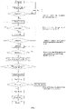
FIG. 4 depicts a schematic flowchart of a controlling method according to an embodiment. - The present invention will be illustrated in further detail below in conjunction with the accompanying drawings and specific embodiments.
- Embodiment I: As shown in
FIGs. 1 ,2 and3 , this example is directed to a household plant essential oil extractor, which includes a plant essentialoil separation device 1, a plant essentialoil collection device 2, abase component 3, acontrol component 4, aheat dissipation component 5, amain body 6, a heatconductive cup body 7, and a heatabsorption cup body 8. Themain body 6 is arranged on thebase component 3. Each of thecontrol component 4, theheat dissipation component 5, and the heatconductive cup body 7 is arranged inside themain body 6. A heating unit 9 is arranged on an outer side wall of the heatconductive cup body 7. The heatabsorption cup body 8 is arranged inside the heatconductive cup body 7. A first temperature detection device is arranged on the heating unit 9. A secondtemperature detection device 10 is arranged at the bottom of the heatabsorption cup body 8. Thecontrol component 4 is electrically connected to the first temperature detection device and the secondtemperature detection device 10, respectively. The plant essentialoil separation device 1 is detachably arranged inside the heatabsorption cup body 8, and the plant essentialoil collection device 2 is detachably arranged on the plant essentialoil separation device 1. - The household plant essential oil extractor of this embodiment is simple in structure and is easy in operation for separating and collecting essential oil. In particular, the plant essential
oil separation device 1 is configured for separating the plant essential oil. And the plant essentialoil collection device 2 is configured for collecting the plant essential oil. Thereby the separation and collection operations for the plant essential oil could be more convenient. - In addition, by means of the arrangement of the first temperature detection device on the heating unit 9, the temperature detection by the heating unit 9 could be performed more accurately, on this basis, data with improved accuracy can be provided for the control of the operation of the plant essential oil extractor by the
control component 4. Thecontrol component 4 could control the operation of the plant essential oil extractor with improved accuracy and stability, so as to avoid the destruction of the main components of the plant essential oil during operation. - The plant essential
oil separation device 1 is inside the heatabsorption cup body 8, and the plant essentialoil collection device 2 is outside the heatabsorption cup body 8. After a plant and plant essential oil are subjected to programmed baking and extraction set in the plant essential oil extractor, a mixture of the plant and the plant essential oil is obtained. And by operating the plant essentialoil separation device 1, the plant is separated from the plant essential oil, and the essential oil is collected by means of the plant essential oil collection - The heating unit 9 and the first temperature detection device are arranged on an outer side wall of the heat
conductive cup body 7. The baking, extraction temperature and time were set in thecontrol component 4 for different plants by a program, and thecontrol component 4 controls the operation of the heating unit 9 such that the temperature of the liquid in the heatabsorption cup body 8 could be kept at a temperature as set. - Compared with the related art, the present household plant essential oil extractor could perform constant temperature baking, extraction, separation and collection for various plants at a preset temperature for a preset time, could ensure successful extraction of the main components of the plant essential oil without being destroyed, and is easy in operation for separation and collection.
- In this embodiment, the plant essential
oil separation device 1 includes afunnel 101, afilter screen component 102, and afilter tube 103. thefilter screen component 102 is arranged in an inlet of thefunnel 101, and thefilter tube 103 is connected to an outlet of thefunnel 101. When using the plant essential oil extractor of this embodiment, the plant is first placed into the heatabsorption cup body 8, the heating unit 9 is activated to dry the plant, and a liquid is then added into the heatabsorption cup body 8. The liquid added to the heatabsorption cup body 8 may be alcohol or oil or any liquid for extracting various plant essential oils. The heating unit 9 is activated to heat and extract the dried plant and the liquid. Once the heating of the plant and the liquid is completed, the heatabsorption cup body 8 is placed upside down, the liquid would be filtered through thefilter screen component 102 and then flow out through thefunnel 101 and thefilter tube 103, with the plant remained in the heatabsorption cup body 8 due to being blocked by thefilter screen component 102, thus realizing separation of the plant from the liquid and achieving effective extraction of the plant. - Preferably, the plant essential
oil collection device 2 includes acollection tube 201 and asealing kit 202. A lower end of thecollection tube 201 is connected to an upper end of thefilter tube 103. Thesealing kit 202 is sleeved outside or inside the joint where thecollection tube 201 and thefilter tube 103 connect. When collecting the essential oil, the lower end of thecollection tube 201 is connected to the upper end of thefilter tube 103, thesealing kit 202 is sleeved outside the joint where thecollection tube 201 and thefilter tube 103 connect. The plant essentialoil separation device 1 is then pressed down, the upper end of thecollection tube 201 is tightened, and under the action of the plant essentialoil separation device 1 and atmospheric pressure, the plant essential oil is pressed into thecollection tube 201 and temporarily stored in thecollection tube 201. When the essential oil in thecollection tube 201 is to be released, it is only necessary to loosen the upper end of thecollection tube 201, whereby the essential oil would flow into a storage container due to the gravity. - More preferably, the heating unit 9 covers the outer side wall of the heat
conductive cup body 7. The heating unit 9 is externally covered with anelastic sleeve 11, and the heating unit 9 is fixed on the outer side wall of the heatconductive cup body 7 via theelastic sleeve 11. The above structure is simple, and the contact area between the heating unit 9 and the heatconductive cup body 7 could thus be increased, thereby effectively improving the heating efficiency of the heatconductive cup body 7 and power saving. In addition, theelastic sleeve 11 as arranged could facilitate the mounting and fixation of the heating unit 9, could also improve the safety and reliability of the use thereof, and effectively prevented the heating unit 9 from contacting other components and causing damage to the other components due to heat. - In this embodiment, the second
temperature detection device 10 includes a film temperature sensor, an internally connected electric ring, an externally connected electric ring, and a silica gel pad. The film temperature sensor, the internally connected electric ring, and the externally connected electric ring are attached to the bottom of the heatabsorption cup body 8. A contact of the film temperature sensor is connected to the internally connected electric ring, and another contact is connected to the externally connected electric ring. And the film temperature sensor, the internally connected electric ring, and the externally connected electric ring are fixed at the bottom of the heatabsorption cup body 8 by means of the silica gel pad. The above structure is simple and compact, and the design is rational and ingenious. The silica gel pad as arranged could facilitate the fixation and mounting of the film temperature sensor, the internally connected electric ring and the externally connected electric ring. In addition, the silica gel pad had a cushioning effect and could thus effectively protect the heatabsorption cup body 8 made of glass. Furthermore, the noise generated when the heatabsorption cup body 8 is taken and placed could be reduced, which is beneficial to improving the user experience. - In this embodiment, the
main body 6 is detachably mounted on thebase component 3, themain body 6 is rotatable relative to thebase component 3. Thecontrol component 4 includes acircuit board 401, thecircuit board 401 is provided with arotary switch 402, thebase component 3 is connected to therotary switch 402. And apositioning structure 301 cooperating with therotary switch 402 is arranged on thebase component 3. - When the plant essential oil extractor of this embodiment is in use, when the user rotates the
main body 6, thecircuit board 401 and therotary switch 402 on thecircuit board 401 would be rotated relative to the base component. Therotary switch 402 would output a signal to thecircuit board 401, and the circuit board starts the corresponding operating mode according to the signal output by therotary switch 402. In addition, by means of the first temperature sensor and the second temperature sensor, the heating unit is controlled, and the temperature and timing of the heating unit are thus controlled. The extractor is simple in structure and is safe, reliable, and convenient to use, which could improve the user experience. For example, different modes of the plant essential oil extractor, e.g., baking mode, could be selected by rotating themain body 6. For the specific structures and descriptions of therotary switch 402 and thepositioning structure 301, reference can be made to the patentCN210043773U , which will not be repeated here to avoid repetition. - Embodiment II. As shown in
FIGs. 1 ,2 and3 , this embodiment provides a method for operating a household plant essential oil extractor, which operating method is applied to the household plant essential oil extractor as described in Embodiment I, and the operating method includes the following steps. - Part of a plant, which might be roots, flowers, leaves, etc., is put into the heat
absorption cup body 8, the heat absorption cup body is covered with a cup cover, and the heatabsorption cup body 8 is then put into the heatconductive cup body 7, in which the cup cover is an ordinary cup cover. And when heating is to be performed, the cup body is placed on top of the heatabsorption cup body 8. - A power supply is turned on for standby and a corresponding baking function is selected, specifically, the selection of the corresponding baking function (mode) is performed by rotating the
main body 6. - After baking, i.e., after the system completed baking, an oil or alcohol is added into the heat
absorption cup body 8 and the corresponding extraction function is selected, specifically, an oil extraction function is to be selected in case the oil is added into the heatabsorption cup body 8, or an alcohol extraction function is to be selected in case alcohol is added into the heatabsorption cup body 8. It is clear that, the selection for either the oil extraction function or the alcohol extraction function could be achieved by rotation of themain body 6. - The cup cover is removed and the plant essential
oil separation device 1 is then mounted on the heatabsorption cup body 8. - After the plant essential oil extractor completes extraction, the heat
absorption cup body 8 is taken out from the heatconductive cup body 7. - The essential oil in the heat
absorption cup body 8 is separated from the plant by means of the plant essentialoil separation device 1, specifically by turning over the heatabsorption cup body 8, holding the plant essentialoil separation device 1, specifically holding the lower end of thefilter tube 103, and slowly pressing down the plant essentialoil separation device 1 to separate the essential oil extracted in the heatabsorption cup body 8 from the plant. - When the plant essential
oil separation device 1 is pressed down to the bottom of the heatabsorption cup body 8, the plant essentialoil separation device 1 is taken out, water or a liquid with a density greater than that of the plant essential oil is added into the heatabsorption cup body 8, the plant essentialoil separation device 1 is mounted on the heatabsorption cup body 8, the plant essentialoil collection device 2 is mounted on the plant essentialoil separation device 1, the plant essentialoil separation device 1 is slowly pressed down to separate the essential oil from the plant and the water or the liquid with a density greater than that of the plant essential oil, the separated essential oil is collected by means of the plant essentialoil collection device 2. And the finally collected plant essential oil is stored in thecollection tube 201. When collecting the essential oil, the lower end of thecollection tube 201 is connected to the upper end of thefilter tube 103, thesealing kit 202 is sleeved outside the joint where thecollection tube 201 and thefilter tube 103 connect, the plant essentialoil separation device 1 is then pressed down, the upper end of thecollection tube 201 is tightened, and under the action of the plant essentialoil separation device 1 and atmospheric pressure, the plant essential oil is pressed into thecollection tube 201 and temporarily stored in thecollection tube 201. When the essential oil in thecollection tube 201 is to be released, it is only necessary to loosen the upper end of thecollection tube 201, whereby the essential oil would flow into a storage container due to the gravity. - As shown in
FIGs. 1 ,2 and4 , the control method for the plant essential oil extractor provided by this embodiment is described below and the method includes the following steps. - The power supply is turned on for standby;
- The
main body 6 is rotated for mode selection; - The system is started and detection is performed as to whether the heat
absorption cup body 8 is held in place. And if the heatabsorption cup body 8 is in place, heating is started, or if the heatabsorption cup body 8 is not in place, a further detection as to whether the heatabsorption cup body 8 is in place is performed after 10 s, and if the heat absorption cup body is still not in place after 30 s, the system exited and entered standby; - After heating is started, detection is performed as to whether the temperature of the heating unit 9 reaches the set temperature and whether the temperature of the heating unit 9 is higher than 100°C. And specifically, the temperature of the heating unit 9 is detected by means of the first temperature detection device, in which when the temperature of the heating unit 9 is higher than 100°C, the
heat dissipation component 5, i.e., a fan, is started, and when the temperature of the heating unit 9 reached the set temperature, the set temperature is maintained. - The detection of whether the temperature of the heat
absorption cup body 8 reaches the set temperature i is specifically performed by the temperature detection of the heatabsorption cup body 8 by means of the second temperature detection device. - The system starts timing, and the duration of the operation varies from 40 to 150 minutes depending on the operating mode.
- The operating mode of the heating unit 9 is adjusted; and specifically, when the temperature of the heat
absorption cup body 8 is lower than the set temperature, heating is started, and when the temperature of the heatabsorption cup body 8 is higher than the set temperature, heating is stopped. - Timing is completed.
- Heating is stopped.
- Detection is performed as to whether the temperature of the heating unit 9 is lower than 50°C is performed.
- If the temperature of the heating unit 9 is higher than 50°C, the
heat dissipation component 5 is controlled for maintaining the operation; and if the temperature of the heating unit 9 is lower than 50°C, the user is informed that the system has completed the operation, specifically by alerting the user with a buzzer sound. - The system enters the standby state.
- Only some embodiments of the present invention are described above. For those of ordinary skill in the art, without departing from the inventive concept of the present invention, various modifications and improvements can also be made and these all fall within the scope of protection of the present invention.
Claims (9)
- A household plant essential oil extractor, characterized by comprising a plant essential oil separation device (1), a plant essential oil collection device (2), and a heat absorption cup body (8), wherein the plant essential oil separation device (1) is detachably arranged inside the heat absorption cup body (8) and is configured for filtering a plant essential oil inside the heat absorption cup body (8), and the plant essential oil collection device (2) is detachably arranged on the plant essential oil separation device (1) and is configured for collecting the filtered plant essential oil.
- The household plant essential oil extractor according to claim 1, characterized in that the plant essential oil separation device (1) comprises a funnel (101), a filter screen component (102), and a filter tube (103), wherein the filter screen component (102) is arranged within an inlet of the funnel (101), and the filter tube (103) is connected to an outlet of the funnel (101).
- The household plant essential oil extractor according to claim 1, characterized in by further comprising a base component (3), a control component (4), a heat dissipation component (5), a main body (6), and a heat conductive cup body (7); wherein the main body (6) is arranged on the base component (3); each of the control component (4), the heat dissipation component (5), and the heat conductive cup body (7) is arranged inside the main body (6); a heating unit (9) is arranged on an outer side wall of the heat conductive cup body (7); the heat absorption cup body (8) is arranged inside the heat conductive cup body (7); a first temperature detection device is arranged on the heating unit (9), a second temperature detection device (10) is arranged at the bottom of the heat absorption cup body (8); and the control component (4) is electrically connected to the first temperature detection device and the second temperature detection device (10), respectively.
- The household plant essential oil extractor according to claim 2, characterized in that the plant essential oil collection device (2) comprises a collection tube (201) and a sealing kit (202), wherein a lower end of the collection tube (201) is connected to an upper end of the filter tube (103), and the sealing kit (202) is sleeved outside or inside a joint where the collection tube (201) and the filter tube (103) connect.
- The household plant essential oil extractor according to any one of claims 2, 3 or 4, characterized in that the second temperature detection device (10) comprises a film temperature sensor, an internally connected electric ring, an externally connected electric ring, and a silica gel pad, wherein the film temperature sensor, the internally connected electric ring, and the externally connected electric ring are attached to the bottom of the heat absorption cup body (8); a contact of the film temperature sensor is connected to the internally connected electric ring, another contact is connected to the externally connected electric ring; and the film temperature sensor, the internally connected electric ring, and the externally connected electric ring are fixed at the bottom of the heat absorption cup body (8) by means of the silica gel pad.
- The household plant essential oil extractor according to any one of claims 2, 3 or 4, characterized in that the main body (6) is detachably mounted on the base component (3), the main body (6) is rotatable relative to the base component (3); the control component (4) comprises a circuit board (401), the circuit board (401) is provided with a rotary switch (402), the base component (3) is connected to the rotary switch (402), and a positioning structure (301) that cooperates with the rotary switch (402) is arranged on the base component (3).
- A method for operating a household plant essential oil extractor, characterized in that the operating method applies to the household plant essential oil extractor according to any one of claims 2 to 6, and the operating method comprises the following steps:placing the roots or leaves or flowers of a plant into the heat absorption cup body (8), covering the heat absorption cup body with a cup cover, and then placing the heat absorption cup body (8) into the heat conductive cup body (7);turning on a power supply for standby and selecting a corresponding baking function;after baking, adding an oil or alcohol into the heat absorption cup body (8) and selecting a corresponding extraction function;removing the cup cover and then mounting the plant essential oil separation device (1) onto the heat absorption cup body (8);after extraction, taking out the heat absorption cup body (8) from the heat conductive cup body (7);separating an essential oil in the heat absorption cup body (8) from the plant by means of the plant essential oil separation device (1); andadding water or a liquid with a density greater than that of the plant essential oil to the heat absorption cup body (8), mounting the plant essential oil collection device (2) onto the plant essential oil separation device (1), slowly pressing down the plant essential oil separation device (1) to separate the essential oil from the plant and the water or the liquid with a density greater than that of the plant essential oil, and collecting the separated essential oil by means of the plant essential oil collection device (2).
- The method for operating a household plant essential oil extractor according to claim 7, characterized in that the step of adding the oil or alcohol into the heat absorption cup body (8) and selecting the corresponding extraction function specifically comprises:selecting an oil extraction function if the oil is added to the heat absorption cup body (8); orselecting an alcohol extraction function if alcohol is added to the heat absorption cup body (8).
- The method for operating a household plant essential oil extractor according to claim 8, characterized in that the step of separating the essential oil in the heat absorption cup body (8) from the plant by means of the plant essential oil separation device (1) specifically comprises:
turning over the heat absorption cup body (8), holding the plant essential oil separation device (1), and slowly pressing down the plant essential oil separation device (1) to separate the essential oil in the heat absorption cup body (8) from the plant.
Applications Claiming Priority (2)
| Application Number | Priority Date | Filing Date | Title |
|---|---|---|---|
| CN202010180495.6A CN111205930B (en) | 2020-03-16 | 2020-03-16 | A household plant essential oil extraction machine and its operating method |
| PCT/CN2021/080217 WO2021185145A1 (en) | 2020-03-16 | 2021-03-11 | Household plant essential oil extractor and operation method therefor |
Publications (4)
| Publication Number | Publication Date |
|---|---|
| EP4123002A1 true EP4123002A1 (en) | 2023-01-25 |
| EP4123002A4 EP4123002A4 (en) | 2024-04-17 |
| EP4123002B1 EP4123002B1 (en) | 2025-12-03 |
| EP4123002C0 EP4123002C0 (en) | 2025-12-03 |
Family
ID=70782995
Family Applications (1)
| Application Number | Title | Priority Date | Filing Date |
|---|---|---|---|
| EP21771810.5A Active EP4123002B1 (en) | 2020-03-16 | 2021-03-11 | Household plant essential oil extractor |
Country Status (4)
| Country | Link |
|---|---|
| US (1) | US20230133196A1 (en) |
| EP (1) | EP4123002B1 (en) |
| CN (1) | CN111205930B (en) |
| WO (1) | WO2021185145A1 (en) |
Families Citing this family (3)
| Publication number | Priority date | Publication date | Assignee | Title |
|---|---|---|---|---|
| CN111205930B (en) * | 2020-03-16 | 2024-03-15 | 中山景泓达智能科技有限公司 | A household plant essential oil extraction machine and its operating method |
| CN115445237B (en) * | 2022-09-29 | 2024-11-12 | 贵州朗佑堂制药有限公司 | A plant extraction method |
| USD1120053S1 (en) * | 2024-10-16 | 2026-03-24 | Wernard Bruining | Oil extraction device |
Family Cites Families (13)
| Publication number | Priority date | Publication date | Assignee | Title |
|---|---|---|---|---|
| US9272230B2 (en) * | 2011-02-18 | 2016-03-01 | Richard Myers | Oil extraction device for use at home and method of use |
| CN104812453A (en) * | 2012-06-21 | 2015-07-29 | 阿罗马托尔有限责任公司 | Distillation apparatus for extracting essential oils and hydrosols from plant matter in containers |
| US10166491B2 (en) * | 2015-01-21 | 2019-01-01 | Lisa F. Kinney | Apparatus and method for extracting organic compounds from plant material using carbon dioxide |
| CN105154236B (en) * | 2015-09-23 | 2018-08-14 | 陈富强 | Full-automatic electric heating triple-effect plant essential oil extraction and purification integrated device |
| CN105505581A (en) * | 2016-01-21 | 2016-04-20 | 中山市宏海塑胶科技有限公司 | Household essential oil extractor |
| CN207175895U (en) * | 2017-09-14 | 2018-04-03 | 黑龙江聚拢华玺智能科技有限公司 | A kind of family expenses extraction of essential oil machine |
| CN208414360U (en) * | 2018-05-15 | 2019-01-22 | 重庆市洲仨科技发展有限公司 | A kind of essential oil extraction device |
| CN108968685A (en) * | 2018-09-30 | 2018-12-11 | 芜湖艾尔达科技有限责任公司 | A kind of portable electric heating coffee machine |
| CN210043773U (en) | 2019-03-11 | 2020-02-11 | 柴矗 | Liquid heater |
| CN209808025U (en) * | 2019-03-18 | 2019-12-20 | 芜湖艾尔达科技有限责任公司 | Can assemble portable beverage extraction device |
| CN110564511A (en) * | 2019-09-20 | 2019-12-13 | 任杰 | Essential oil refining equipment |
| CN111205930B (en) * | 2020-03-16 | 2024-03-15 | 中山景泓达智能科技有限公司 | A household plant essential oil extraction machine and its operating method |
| CN212222913U (en) * | 2020-03-16 | 2020-12-25 | 中山景泓达智能科技有限公司 | A household plant essential oil extraction machine |
-
2020
- 2020-03-16 CN CN202010180495.6A patent/CN111205930B/en active Active
-
2021
- 2021-03-11 EP EP21771810.5A patent/EP4123002B1/en active Active
- 2021-03-11 US US17/906,494 patent/US20230133196A1/en active Pending
- 2021-03-11 WO PCT/CN2021/080217 patent/WO2021185145A1/en not_active Ceased
Also Published As
| Publication number | Publication date |
|---|---|
| CN111205930B (en) | 2024-03-15 |
| WO2021185145A1 (en) | 2021-09-23 |
| CN111205930A (en) | 2020-05-29 |
| EP4123002A4 (en) | 2024-04-17 |
| US20230133196A1 (en) | 2023-05-04 |
| EP4123002B1 (en) | 2025-12-03 |
| EP4123002C0 (en) | 2025-12-03 |
Similar Documents
| Publication | Publication Date | Title |
|---|---|---|
| EP4123002B1 (en) | Household plant essential oil extractor | |
| TWI439242B (en) | Electric pressure cooker with function of rapid pressure relief | |
| CN108305699A (en) | Intelligent multi-function removes radioactive contamination instrument | |
| CN212222913U (en) | A household plant essential oil extraction machine | |
| CN113230574A (en) | Dry dampproofing portable fire control that has self-checking function patrols and examines cabinet | |
| CN108741144A (en) | Vegetables cleaning device | |
| CN208943508U (en) | A kind of basket extractor | |
| CN212470427U (en) | Simple bearing heater | |
| CN217448451U (en) | Herbal pieces-is with frying medicine machine with smoke and dust processing mechanism | |
| CN204334914U (en) | Hearing aid intelligent maintenance instrument | |
| CN214177640U (en) | Prevent outage integrated circuit board | |
| CN109696321A (en) | Food medicament residue sampler | |
| CN210801871U (en) | Vacuum drying device for drying natural plant extracts | |
| CN210427048U (en) | A device for extracting exfoliated cells | |
| CN207883338U (en) | Intelligent multi-function removes radioactive contamination device | |
| CN221655629U (en) | An adsorption type electrical stimulation device | |
| CN218773728U (en) | Smokeless hot pot | |
| CN221148222U (en) | Solid component collecting device for atmospheric detection | |
| CN110624621A (en) | Chemical experiment operation panel | |
| CN222723639U (en) | Agilawood tablet powder liquid extraction device | |
| CN204513918U (en) | Audiphone care device | |
| CN223695543U (en) | A quick-release juicer | |
| CN110864734B (en) | An information collection device and collection method for big data that is convenient for ensuring security | |
| CN215574089U (en) | Plant sample pretreatment device | |
| CN219897121U (en) | High-efficient traditional chinese medicine extraction element |
Legal Events
| Date | Code | Title | Description |
|---|---|---|---|
| STAA | Information on the status of an ep patent application or granted ep patent |
Free format text: STATUS: THE INTERNATIONAL PUBLICATION HAS BEEN MADE |
|
| PUAI | Public reference made under article 153(3) epc to a published international application that has entered the european phase |
Free format text: ORIGINAL CODE: 0009012 |
|
| STAA | Information on the status of an ep patent application or granted ep patent |
Free format text: STATUS: REQUEST FOR EXAMINATION WAS MADE |
|
| 17P | Request for examination filed |
Effective date: 20220901 |
|
| AK | Designated contracting states |
Kind code of ref document: A1 Designated state(s): AL AT BE BG CH CY CZ DE DK EE ES FI FR GB GR HR HU IE IS IT LI LT LU LV MC MK MT NL NO PL PT RO RS SE SI SK SM TR |
|
| DAV | Request for validation of the european patent (deleted) | ||
| DAX | Request for extension of the european patent (deleted) | ||
| A4 | Supplementary search report drawn up and despatched |
Effective date: 20240319 |
|
| RIC1 | Information provided on ipc code assigned before grant |
Ipc: B01D 11/02 20060101ALI20240313BHEP Ipc: C11B 9/02 20060101AFI20240313BHEP |
|
| GRAP | Despatch of communication of intention to grant a patent |
Free format text: ORIGINAL CODE: EPIDOSNIGR1 |
|
| STAA | Information on the status of an ep patent application or granted ep patent |
Free format text: STATUS: GRANT OF PATENT IS INTENDED |
|
| GRAS | Grant fee paid |
Free format text: ORIGINAL CODE: EPIDOSNIGR3 |
|
| INTG | Intention to grant announced |
Effective date: 20250930 |
|
| RIC1 | Information provided on ipc code assigned before grant |
Ipc: C11B 9/02 20060101AFI20250919BHEP Ipc: B01D 11/02 20060101ALI20250919BHEP |
|
| GRAA | (expected) grant |
Free format text: ORIGINAL CODE: 0009210 |
|
| STAA | Information on the status of an ep patent application or granted ep patent |
Free format text: STATUS: THE PATENT HAS BEEN GRANTED |
|
| AK | Designated contracting states |
Kind code of ref document: B1 Designated state(s): AL AT BE BG CH CY CZ DE DK EE ES FI FR GB GR HR HU IE IS IT LI LT LU LV MC MK MT NL NO PL PT RO RS SE SI SK SM TR |
|
| REG | Reference to a national code |
Ref country code: CH Ref legal event code: F10 Free format text: ST27 STATUS EVENT CODE: U-0-0-F10-F00 (AS PROVIDED BY THE NATIONAL OFFICE) Effective date: 20251203 Ref country code: GB Ref legal event code: FG4D |
|
| REG | Reference to a national code |
Ref country code: DE Ref legal event code: R096 Ref document number: 602021043664 Country of ref document: DE |
|
| REG | Reference to a national code |
Ref country code: CH Ref legal event code: R17 Free format text: ST27 STATUS EVENT CODE: U-0-0-R10-R17 (AS PROVIDED BY THE NATIONAL OFFICE) Effective date: 20251219 |
|
| REG | Reference to a national code |
Ref country code: IE Ref legal event code: FG4D |
|
| U01 | Request for unitary effect filed |
Effective date: 20251203 |
|
| U07 | Unitary effect registered |
Designated state(s): AT BE BG DE DK EE FI FR IT LT LU LV MT NL PT RO SE SI Effective date: 20251212 |
|
| REG | Reference to a national code |
Ref country code: CH Ref legal event code: U11 Free format text: ST27 STATUS EVENT CODE: U-0-0-U10-U11 (AS PROVIDED BY THE NATIONAL OFFICE) Effective date: 20260401 |
|
| PGFP | Annual fee paid to national office [announced via postgrant information from national office to epo] |
Ref country code: GB Payment date: 20260324 Year of fee payment: 6 |
|
| PG25 | Lapsed in a contracting state [announced via postgrant information from national office to epo] |
Ref country code: ES Free format text: LAPSE BECAUSE OF FAILURE TO SUBMIT A TRANSLATION OF THE DESCRIPTION OR TO PAY THE FEE WITHIN THE PRESCRIBED TIME-LIMIT Effective date: 20251203 |
|
| PG25 | Lapsed in a contracting state [announced via postgrant information from national office to epo] |
Ref country code: NO Free format text: LAPSE BECAUSE OF FAILURE TO SUBMIT A TRANSLATION OF THE DESCRIPTION OR TO PAY THE FEE WITHIN THE PRESCRIBED TIME-LIMIT Effective date: 20260303 |
|
| PGFP | Annual fee paid to national office [announced via postgrant information from national office to epo] |
Ref country code: IE Payment date: 20260319 Year of fee payment: 6 |
|
| PG25 | Lapsed in a contracting state [announced via postgrant information from national office to epo] |
Ref country code: HR Free format text: LAPSE BECAUSE OF FAILURE TO SUBMIT A TRANSLATION OF THE DESCRIPTION OR TO PAY THE FEE WITHIN THE PRESCRIBED TIME-LIMIT Effective date: 20251203 |
|
| PG25 | Lapsed in a contracting state [announced via postgrant information from national office to epo] |
Ref country code: RS Free format text: LAPSE BECAUSE OF FAILURE TO SUBMIT A TRANSLATION OF THE DESCRIPTION OR TO PAY THE FEE WITHIN THE PRESCRIBED TIME-LIMIT Effective date: 20260303 |
|
| PG25 | Lapsed in a contracting state [announced via postgrant information from national office to epo] |
Ref country code: PL Free format text: LAPSE BECAUSE OF FAILURE TO SUBMIT A TRANSLATION OF THE DESCRIPTION OR TO PAY THE FEE WITHIN THE PRESCRIBED TIME-LIMIT Effective date: 20251203 |
|
| U20 | Renewal fee for the european patent with unitary effect paid |
Year of fee payment: 6 Effective date: 20260326 |