EP4122875A1 - Robotized manifold system comprising a plurality of bistable valves - Google Patents
Robotized manifold system comprising a plurality of bistable valves Download PDFInfo
- Publication number
- EP4122875A1 EP4122875A1 EP21186387.3A EP21186387A EP4122875A1 EP 4122875 A1 EP4122875 A1 EP 4122875A1 EP 21186387 A EP21186387 A EP 21186387A EP 4122875 A1 EP4122875 A1 EP 4122875A1
- Authority
- EP
- European Patent Office
- Prior art keywords
- robotized
- series
- manifold system
- pipes
- pipe
- Prior art date
- Legal status (The legal status is an assumption and is not a legal conclusion. Google has not performed a legal analysis and makes no representation as to the accuracy of the status listed.)
- Granted
Links
Images


Classifications
-
- F—MECHANICAL ENGINEERING; LIGHTING; HEATING; WEAPONS; BLASTING
- F16—ENGINEERING ELEMENTS AND UNITS; GENERAL MEASURES FOR PRODUCING AND MAINTAINING EFFECTIVE FUNCTIONING OF MACHINES OR INSTALLATIONS; THERMAL INSULATION IN GENERAL
- F16L—PIPES; JOINTS OR FITTINGS FOR PIPES; SUPPORTS FOR PIPES, CABLES OR PROTECTIVE TUBING; MEANS FOR THERMAL INSULATION IN GENERAL
- F16L41/00—Branching pipes; Joining pipes to walls
- F16L41/02—Branch units, e.g. made in one piece, welded, riveted
- F16L41/03—Branch units, e.g. made in one piece, welded, riveted comprising junction pieces for four or more pipe members
-
- B—PERFORMING OPERATIONS; TRANSPORTING
- B67—OPENING, CLOSING OR CLEANING BOTTLES, JARS OR SIMILAR CONTAINERS; LIQUID HANDLING
- B67D—DISPENSING, DELIVERING OR TRANSFERRING LIQUIDS, NOT OTHERWISE PROVIDED FOR
- B67D7/00—Apparatus or devices for transferring liquids from bulk storage containers or reservoirs into vehicles or into portable containers, e.g. for retail sale purposes
- B67D7/06—Details or accessories
- B67D7/78—Arrangements of storage tanks, reservoirs or pipe-lines
-
- B—PERFORMING OPERATIONS; TRANSPORTING
- B25—HAND TOOLS; PORTABLE POWER-DRIVEN TOOLS; MANIPULATORS
- B25J—MANIPULATORS; CHAMBERS PROVIDED WITH MANIPULATION DEVICES
- B25J11/00—Manipulators not otherwise provided for
-
- F—MECHANICAL ENGINEERING; LIGHTING; HEATING; WEAPONS; BLASTING
- F16—ENGINEERING ELEMENTS AND UNITS; GENERAL MEASURES FOR PRODUCING AND MAINTAINING EFFECTIVE FUNCTIONING OF MACHINES OR INSTALLATIONS; THERMAL INSULATION IN GENERAL
- F16K—VALVES; TAPS; COCKS; ACTUATING-FLOATS; DEVICES FOR VENTING OR AERATING
- F16K11/00—Multiple-way valves, e.g. mixing valves; Pipe fittings incorporating such valves
- F16K11/10—Multiple-way valves, e.g. mixing valves; Pipe fittings incorporating such valves with two or more closure members not moving as a unit
- F16K11/20—Multiple-way valves, e.g. mixing valves; Pipe fittings incorporating such valves with two or more closure members not moving as a unit operated by separate actuating members
- F16K11/22—Multiple-way valves, e.g. mixing valves; Pipe fittings incorporating such valves with two or more closure members not moving as a unit operated by separate actuating members with an actuating member for each valve, e.g. interconnected to form multiple-way valves
-
- F—MECHANICAL ENGINEERING; LIGHTING; HEATING; WEAPONS; BLASTING
- F16—ENGINEERING ELEMENTS AND UNITS; GENERAL MEASURES FOR PRODUCING AND MAINTAINING EFFECTIVE FUNCTIONING OF MACHINES OR INSTALLATIONS; THERMAL INSULATION IN GENERAL
- F16K—VALVES; TAPS; COCKS; ACTUATING-FLOATS; DEVICES FOR VENTING OR AERATING
- F16K31/00—Actuating devices; Operating means; Releasing devices
- F16K31/003—Actuating devices; Operating means; Releasing devices operated without a stable intermediate position, e.g. with snap action
Definitions
- the present invention concerns a robotized manifold system comprising a plurality of bistable valves.
- the manifold system is used at all stages of the process, for conveying and/or mixing raw materials, semi-finished products and finished products.
- the manifold system comprises pipes and valves to define different piping configurations.
- the pipes should be conceived and installed to be easily cleaned, for example thanks to pigs that circulate in the manifold system to push the remaining fluid outside the pipes.
- the present invention aims to solve all or some of the disadvantages mentioned above.
- the present invention relates to a robotized manifold system comprising:
- the pipe matrix comprises a first layer and a second layer for conveying fluids and each bistable valve either separates a pipe of the first series and a pipe of the second series or links said pipes.
- Bistable valve means that when actuated from one position to the other, said bistable valve remains in position. There is no need to physically maintain the valve after actuation.
- transverse or transversally it means constituting an angle of at least 30°.
- Each bistable valve can be actuated mechanically and independently with a single mechanical actuator, i.e. the arm.
- the pipe matrix comprises at least two walls extending transversally, the robotized manifold system can have a limited size.
- the arm used as a single mechanical actuator of the plurality of bistable valves enables to minimize the equipment used for actuation. This engenders free space in proximity of the bistable valves which facilitates the installation of the robotized manifold system in a reduced space.
- each shutter body of the plurality of bistable valves is arranged to rotate between the line position and the transverse position according to an actuating axis transverse to an extension plane of the wall on which said shutter body is installed.
- the shutter bodies of the bistable valves of a wall have therefore the same orientation which is transverse to said wall. This provision allows to easily and reliably actuate the bistable valves with the arm. Indeed, the arm can move from one valve to the other and rotate the corresponding shutter body.
- each bistable valve comprises a removable external flange, the corresponding shutter body being withdrawable from the rest of said bistable valve transversally to the extension plane of the wall on which said shutter body is installed when the external flange is removed.
- each bistable valve comprises two removable external flanges on both of its extremities to allow to withdraw the shutter body from both sides of the wall.
- each external flange presents a central access window to an actuating element of the corresponding shutter body.
- the actuating element is a groove configured to cooperate with an extremity tool of the arm. Said groove can present an oblong form.
- the pipe matrix comprises three walls organized according to a U shape, the robot being located between the two walls facing each other.
- the pipes of the first series each comprises an elbow portion between the at least two walls.
- the first direction has straight portions within the walls and curved portions between the walls.
- each wall comprises of a plurality of valve modules, each valve module comprising bistable valves organized in lines and columns and connecting ports at both ends of the lines to the first series of pipes and at both ends of the columns to the second series of pipes.
- each wall comprises a plurality of prefabricated valve modules.
- the adaptation of the pipe matrix in the factory is easy because the dimensions of the walls is adaptable.
- the pipe matrix comprises a stand assembly arranged to be set on a flat ground, the stand assembly comprising at least two unitary elements, each being dedicated for a corresponding wall, the first direction being horizontal and the second direction being vertical.
- the stand assembly helps placing the walls on the flat ground and align the first direction and the second direction horizontally and vertically.
- the stand assembly comprises feet to position the at least two walls at a determined distance from the flat ground.
- the robotized manifold system comprises lower inlet and outlet pipes linked to corresponding pipes of the second series, said lower inlet and outlet pipes being curved to change from a vertical orientation at a connection area with the pipes of the second series to a horizontal orientation.
- connection area with the pipes of the second series is distant from the flat ground.
- the lower inlet and outlet pipes can then be used to drain the pipes or to connect the pipe matrix with a product source that is set horizontally.
- This construction also participates to the limited size of the robotized manifold system.
- each pipe of the first series and of the second series are configured to enable the circulation of a pig for cleaning said pipe when all the corresponding bistable valves are in line position.
- This construction enables to wash the pipes including the portions corresponding to the inside of the shutter body.
- the pig is designed to scrap the pipes.
- the arm comprises at least three fractions configured to rotate with respect to each other and a centralized command arrangement including sensors for controlling said arm.
- the robotized manifold system comprises a guiding structure configured to receive the robot, the robot being configured to move between two end positions when received in the guiding structure.
- the guiding structure thus enables the arm to actuate a larger set of bistable valves as the robot is movable when received in the guiding structure.
- the guiding structure is configured to enable a displacement of the robot according to a translation between the two end positions.
- the translation is according to a trajectory extending between and parallel to the two walls of the pipe matrix facing each other.
- the guiding structure is a rail structure configured to cooperate with a complementary support structure of the robot.
- the robotized manifold system may not include a guiding structure.
- the robotized manifold system can comprise a base configured to cooperate with the ground and on which the robot is installed. Indeed, it might not be necessary to move the robot depending on the spatial configuration of the robotized manifold system.
- the base can also be integral with the robot.
- the robotized manifold system comprises a protection cage configured to be installed around the plurality of bistable valves and the robot.
- the protection cage comprises joined panels disposed around the walls and the robot.
- each panel comprises at least one transparent portion.
- the protection cage is configured to have a moving portion such as a door to penetrate inside an area defined by the protection cage.
- the present invention also concerns an installation comprising the robotized manifold system and a plant managing entity for controlling the robotized manifold system.
- the plant managing entity is dedicated for the global command of the installation and the synchronization with other machines of the installation that can be coupled with the robotized manifold system.
- a robotized manifold system 1 comprises a pipe matrix 3 including a first series 5 of pipes 7 extending according to a first direction 9 and being comprised in a first layer 11 of the pipe matrix 3 and a second series 13 of pipes 7 extending according to a second direction 15 transverse to the first direction 9 and extending in a second layer 17 of the pipe matrix 3.
- the pipe matrix 3 is organized according to at least two walls 19 extending transversally to each other, each wall 19 comprising a portion of the first layer 11 and the second layer 17.
- the robotized manifold assembly 1 comprises a plurality of bistable valves 21 being distributed on said at least two walls 19, each bistable valve 21 including a shutter body 23 configured to constitute a portion of a pipe 7 of the first series 5 and a portion of a pipe 7 of the second series 13 in a line position and to link said pipes 7 of the first series 5 and second series 13 in a transverse position.
- the robotized manifold assembly 1 also comprises a robot 25 with an arm 27 configured to individually actuate each shutter body 23 of the bistable valves 21.
- the pipe matrix 3 comprises a first layer 11 and a second layer 17 for conveying fluids and each bistable valve 21 either separates a pipe 7 of the first series 5 and a pipe 7 of the second series 13 or links said pipes 7.
- Each bistable valve 21 can be actuated mechanically and independently with a single mechanical actuator, i.e. the arm 27.
- Each shutter body 23 of the plurality of bistable valves 21 is arranged to rotate between the line position and the transverse position according to an actuating axis 29 transverse to an extension plane 31 of the wall 19 on which said shutter body 23 is installed.
- the shutter bodies 23 of the bistable valves 21 of a wall 19 have therefore the same orientation which is transverse to said wall 19.
- Each bistable valve 21 comprises a removable external flange 33, the corresponding shutter body 23 being withdrawable from the rest of said bistable valve 21 transversally to the extension plane 31 of the wall 19 on which said shutter body 23 is installed when the external flange 33 is removed.
- each bistable valve 21 comprises two removable external flanges 33 on both of its extremities to allow to withdraw the shutter body 23 from both sides of the wall 19.
- Each external flange 33 presents a central access window 35 to an actuating element 37 of the corresponding shutter body 23.
- the actuating element 37 is a groove configured to cooperate with an extremity tool of the arm 27. Said groove can present an oblong form.
- the illustrated pipe matrix 3 comprises three walls 19 organized according to a U shape, the robot 25 being located between the two walls 19 facing each other.
- the pipes 7 of the first series 5 each comprises an elbow portion 41 between the at least two walls 19.
- the first direction 9 has straight portions within the walls 19 and curved portions between the walls 19.
- Each wall 19 comprises of a plurality of valve modules 43, each valve module 43 comprising bistable valves 21 organized in lines and columns and connecting ports 45 at both ends of the lines to the first layer 11 of pipes 7 and at both ends of the columns to the second layer 17 of pipes 7.
- the pipe matrix 3 comprises a stand assembly 47 arranged to be set on a flat ground, the stand assembly 47 comprising at least two unitary elements, each being dedicated for a corresponding wall 19, the first direction 9 being horizontal and the second direction 15 being vertical.
- the stand assembly 47 comprises feet to position the at least two walls 19 at a determined distance from the flat ground.
- the robotized manifold system 1 comprises lower inlet and outlet pipes 49 linked to corresponding pipes 7 of the second series 13, said lower inlet and outlet pipes 49 being curved to change from a vertical orientation at a connection area with the pipes 7 of the second series 13 to a horizontal orientation.
- connection area with the pipes 7 of the second series 13 is distant from the flat ground.
- the lower inlet and outlet pipes 49 can then be used to drain the pipes 7 or to connect the pipe matrix 3 with a product source that is set horizontally.
- Each pipe 7 of the first series 5 and of the second series 13 are configured to enable the circulation of a pig for cleaning said pipe 7 when all the corresponding bistable valves 21 are in line position.
- the arm 27 comprises at least three fractions configured to rotate with respect to each other, and a centralized command arrangement 51 including sensors for controlling said arm 27.
- the robotized manifold system 1 comprises a guiding structure 53 configured to receive the robot 25, the robot 25 being configured to move between two end positions when received in the guiding structure 53.
- the guiding structure 53 is configured to enable a displacement of the robot 25 according to a translation between the two end positions.
- the translation is according to a trajectory extending between and parallel to the two walls 19 of the pipe matrix 3 facing each other.
- the guiding structure 53 is a rail structure configured to cooperate with a complementary support structure of the robot 25.
- the robotized manifold system 1 comprises a protection cage 55 configured to be installed around the plurality of bistable valves 21 and the robot 25.
- the protection cage 55 comprises joined panels 57 disposed around the walls 19 and the robot 25. Each panel 57 comprises at least one transparent portion.
- the protection cage 55 is configured to have a moving portion such as a door to penetrate inside an area defined by the protection cage 55.
- the above described robotized manifold system 1 can have a limited size.
- the arm 27 used as a single mechanical actuator of the plurality of bistable valves 21 enables to minimize the equipment used for actuation. This engenders free space in proximity of the bistable valves 21 which facilitates the installation of the robotized manifold system 1 in a reduced space.
Landscapes
- Engineering & Computer Science (AREA)
- General Engineering & Computer Science (AREA)
- Mechanical Engineering (AREA)
- Robotics (AREA)
- Manipulator (AREA)
- Valve Housings (AREA)
Abstract
Description
- The present invention concerns a robotized manifold system comprising a plurality of bistable valves.
- It is known to use a manifold system in industrial applications for preparing products such as lubricants and greases, paints and varnishes, paper, chemicals, perfumes, wherein raw fluids are used to prepare semi-finished products and finished products.
- The manifold system is used at all stages of the process, for conveying and/or mixing raw materials, semi-finished products and finished products. To that purpose, the manifold system comprises pipes and valves to define different piping configurations.
- In addition, the pipes should be conceived and installed to be easily cleaned, for example thanks to pigs that circulate in the manifold system to push the remaining fluid outside the pipes.
- There is therefore a need to actuate the valves in a reliable way. The installation of such a manifold system in an existing factory can become challenging if the space is reduced. The piping as well as the actuation of the valve should also be accessible for maintenance.
- The present invention aims to solve all or some of the disadvantages mentioned above.
- For this purpose, the present invention relates to a robotized manifold system comprising:
- a pipe matrix including a first series of pipes extending according to a first direction and being comprised in a first layer of the pipe matrix and a second series of pipes extending according to a second direction transverse to the first direction and extending in a second layer of the pipe matrix, said pipe matrix being organized according to at least two walls extending transversally to each other or at least one curved wall, each wall comprising a portion of the first layer and the second layer,
- a plurality of bistable valves being distributed on said at least two walls or at least one curved wall, each bistable valve including a shutter body configured to constitute a portion of a pipe of the first series and a portion of a pipe of the second series in a line position and to link said pipes of the first series and second series in a transverse position,
- a robot with an arm configured to individually actuate each shutter body of the bistable valves.
- In other words, the pipe matrix comprises a first layer and a second layer for conveying fluids and each bistable valve either separates a pipe of the first series and a pipe of the second series or links said pipes.
- Bistable valve means that when actuated from one position to the other, said bistable valve remains in position. There is no need to physically maintain the valve after actuation. When the terms transverse or transversally is used, it means constituting an angle of at least 30°.
- Each bistable valve can be actuated mechanically and independently with a single mechanical actuator, i.e. the arm. As the pipe matrix comprises at least two walls extending transversally, the robotized manifold system can have a limited size.
- The arm used as a single mechanical actuator of the plurality of bistable valves enables to minimize the equipment used for actuation. This engenders free space in proximity of the bistable valves which facilitates the installation of the robotized manifold system in a reduced space.
- Maintenance as well is reduced and easy thanks to the reliability of the arm that has few moving parts. The simple design of the robotized manifold system also reduces investment cost.
- According to an aspect of the invention, each shutter body of the plurality of bistable valves is arranged to rotate between the line position and the transverse position according to an actuating axis transverse to an extension plane of the wall on which said shutter body is installed.
- The shutter bodies of the bistable valves of a wall have therefore the same orientation which is transverse to said wall. This provision allows to easily and reliably actuate the bistable valves with the arm. Indeed, the arm can move from one valve to the other and rotate the corresponding shutter body.
- In addition, there is no translation of the shutter body transversally to the corresponding wall. This reduces the overall depth of the walls.
- According to an aspect of the invention, each bistable valve comprises a removable external flange, the corresponding shutter body being withdrawable from the rest of said bistable valve transversally to the extension plane of the wall on which said shutter body is installed when the external flange is removed.
- This provision facilitates the maintenance of the bistable valves. There is no need to dismantle other bistable valves or structural elements of pipe matrix. Preferably, each bistable valve comprises two removable external flanges on both of its extremities to allow to withdraw the shutter body from both sides of the wall.
- According to an aspect of the invention, each external flange presents a central access window to an actuating element of the corresponding shutter body. The actuating element is a groove configured to cooperate with an extremity tool of the arm. Said groove can present an oblong form.
- According to an aspect of the invention, the pipe matrix comprises three walls organized according to a U shape, the robot being located between the two walls facing each other.
- This provision facilitates the actuation of the bistable valves by the arm as the distance to each valve is limited. The overall size of the robotized manifold system is therefore limited.
- There is also a security aspect to this configuration as the robot is surrounded by the walls. This creates a safety zone that could be delimited to prevent access in proximity of the robot when operating.
- According to an aspect of the invention, the pipes of the first series each comprises an elbow portion between the at least two walls.
- In other words, the first direction has straight portions within the walls and curved portions between the walls.
- According to an aspect of the invention, each wall comprises of a plurality of valve modules, each valve module comprising bistable valves organized in lines and columns and connecting ports at both ends of the lines to the first series of pipes and at both ends of the columns to the second series of pipes.
- This provision facilitates the installation of the walls, as each wall comprises a plurality of prefabricated valve modules. The adaptation of the pipe matrix in the factory is easy because the dimensions of the walls is adaptable.
- According to an aspect of the invention, the pipe matrix comprises a stand assembly arranged to be set on a flat ground, the stand assembly comprising at least two unitary elements, each being dedicated for a corresponding wall, the first direction being horizontal and the second direction being vertical.
- The stand assembly helps placing the walls on the flat ground and align the first direction and the second direction horizontally and vertically.
- According to an aspect of the invention, the stand assembly comprises feet to position the at least two walls at a determined distance from the flat ground.
- This provision enables the arm to easily actuate the bistable valves since the lowest bistable valves are distant from the flat ground level.
- According to an aspect of the invention, the robotized manifold system comprises lower inlet and outlet pipes linked to corresponding pipes of the second series, said lower inlet and outlet pipes being curved to change from a vertical orientation at a connection area with the pipes of the second series to a horizontal orientation.
- The connection area with the pipes of the second series is distant from the flat ground. The lower inlet and outlet pipes can then be used to drain the pipes or to connect the pipe matrix with a product source that is set horizontally.
- This construction also participates to the limited size of the robotized manifold system.
- According to an aspect of the invention, each pipe of the first series and of the second series are configured to enable the circulation of a pig for cleaning said pipe when all the corresponding bistable valves are in line position.
- This construction enables to wash the pipes including the portions corresponding to the inside of the shutter body. The pig is designed to scrap the pipes.
- According to an aspect of the invention, the arm comprises at least three fractions configured to rotate with respect to each other and a centralized command arrangement including sensors for controlling said arm.
- According to an aspect of the invention, the robotized manifold system comprises a guiding structure configured to receive the robot, the robot being configured to move between two end positions when received in the guiding structure.
- The guiding structure thus enables the arm to actuate a larger set of bistable valves as the robot is movable when received in the guiding structure. According to an aspect of the invention, the guiding structure is configured to enable a displacement of the robot according to a translation between the two end positions.
- According to an aspect of the invention, the translation is according to a trajectory extending between and parallel to the two walls of the pipe matrix facing each other.
- According to an aspect of the invention, the guiding structure is a rail structure configured to cooperate with a complementary support structure of the robot.
- Alternatively, the robotized manifold system may not include a guiding structure. In that case, the robotized manifold system can comprise a base configured to cooperate with the ground and on which the robot is installed. Indeed, it might not be necessary to move the robot depending on the spatial configuration of the robotized manifold system. The base can also be integral with the robot.
- According to an aspect of the invention, the robotized manifold system comprises a protection cage configured to be installed around the plurality of bistable valves and the robot.
- According to an aspect of the invention, the protection cage comprises joined panels disposed around the walls and the robot. Preferably, each panel comprises at least one transparent portion. In particular, the protection cage is configured to have a moving portion such as a door to penetrate inside an area defined by the protection cage.
- The present invention also concerns an installation comprising the robotized manifold system and a plant managing entity for controlling the robotized manifold system. The plant managing entity is dedicated for the global command of the installation and the synchronization with other machines of the installation that can be coupled with the robotized manifold system.
- The different aspects defined above that are not incompatible can be combined.
- The invention will be better understood with the aid of the detailed description that is set out below with reference to the appended drawing in which:
-
figure 1 is a perspective view of a robotized manifold assembly; -
figure 2 is a perspective view of a valve module of the robotized manifold assembly; -
figure 3 is a perspective view of a robot with an arm and a valve module, -
figure 4 is a top view of the robotized manifold system, -
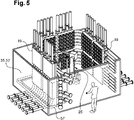
figure 5 is a perspective view of the robotized manifold system with a protection cage. - In the following detailed description of the figures defined above, the same elements or the elements that are fulfilling identical functions may retain the same references so as to simplify the understanding of the invention.
- As illustrated in
figures 1 to 3 , arobotized manifold system 1 comprises apipe matrix 3 including a first series 5 of pipes 7 extending according to afirst direction 9 and being comprised in afirst layer 11 of thepipe matrix 3 and a second series 13 of pipes 7 extending according to asecond direction 15 transverse to thefirst direction 9 and extending in asecond layer 17 of thepipe matrix 3. - The
pipe matrix 3 is organized according to at least twowalls 19 extending transversally to each other, eachwall 19 comprising a portion of thefirst layer 11 and thesecond layer 17. - The robotized
manifold assembly 1 comprises a plurality ofbistable valves 21 being distributed on said at least twowalls 19, eachbistable valve 21 including ashutter body 23 configured to constitute a portion of a pipe 7 of the first series 5 and a portion of a pipe 7 of the second series 13 in a line position and to link said pipes 7 of the first series 5 and second series 13 in a transverse position. - The robotized
manifold assembly 1 also comprises arobot 25 with anarm 27 configured to individually actuate eachshutter body 23 of thebistable valves 21. - In other words, the
pipe matrix 3 comprises afirst layer 11 and asecond layer 17 for conveying fluids and eachbistable valve 21 either separates a pipe 7 of the first series 5 and a pipe 7 of the second series 13 or links said pipes 7. - Each
bistable valve 21 can be actuated mechanically and independently with a single mechanical actuator, i.e. thearm 27. - Each
shutter body 23 of the plurality ofbistable valves 21 is arranged to rotate between the line position and the transverse position according to an actuatingaxis 29 transverse to anextension plane 31 of thewall 19 on which saidshutter body 23 is installed. - The
shutter bodies 23 of thebistable valves 21 of awall 19 have therefore the same orientation which is transverse to saidwall 19. - Each
bistable valve 21 comprises a removableexternal flange 33, thecorresponding shutter body 23 being withdrawable from the rest of saidbistable valve 21 transversally to theextension plane 31 of thewall 19 on which saidshutter body 23 is installed when theexternal flange 33 is removed. - Preferably, each
bistable valve 21 comprises two removableexternal flanges 33 on both of its extremities to allow to withdraw theshutter body 23 from both sides of thewall 19. - Each
external flange 33 presents acentral access window 35 to anactuating element 37 of thecorresponding shutter body 23. Theactuating element 37 is a groove configured to cooperate with an extremity tool of thearm 27. Said groove can present an oblong form. - More specifically, the illustrated
pipe matrix 3 comprises threewalls 19 organized according to a U shape, therobot 25 being located between the twowalls 19 facing each other. - The pipes 7 of the first series 5 each comprises an
elbow portion 41 between the at least twowalls 19. In other words, thefirst direction 9 has straight portions within thewalls 19 and curved portions between thewalls 19. - Each
wall 19 comprises of a plurality ofvalve modules 43, eachvalve module 43 comprisingbistable valves 21 organized in lines and columns and connectingports 45 at both ends of the lines to thefirst layer 11 of pipes 7 and at both ends of the columns to thesecond layer 17 of pipes 7. - The
pipe matrix 3 comprises astand assembly 47 arranged to be set on a flat ground, thestand assembly 47 comprising at least two unitary elements, each being dedicated for acorresponding wall 19, thefirst direction 9 being horizontal and thesecond direction 15 being vertical. - The
stand assembly 47 comprises feet to position the at least twowalls 19 at a determined distance from the flat ground. - The
robotized manifold system 1 comprises lower inlet andoutlet pipes 49 linked to corresponding pipes 7 of the second series 13, said lower inlet andoutlet pipes 49 being curved to change from a vertical orientation at a connection area with the pipes 7 of the second series 13 to a horizontal orientation. - The connection area with the pipes 7 of the second series 13 is distant from the flat ground. The lower inlet and
outlet pipes 49 can then be used to drain the pipes 7 or to connect thepipe matrix 3 with a product source that is set horizontally. - Each pipe 7 of the first series 5 and of the second series 13 are configured to enable the circulation of a pig for cleaning said pipe 7 when all the corresponding
bistable valves 21 are in line position. - As illustrates in
figure 3 , thearm 27 comprises at least three fractions configured to rotate with respect to each other, and acentralized command arrangement 51 including sensors for controlling saidarm 27. - As illustrated in
figure 4 , therobotized manifold system 1 comprises a guidingstructure 53 configured to receive therobot 25, therobot 25 being configured to move between two end positions when received in the guidingstructure 53. - The guiding
structure 53 is configured to enable a displacement of therobot 25 according to a translation between the two end positions. The translation is according to a trajectory extending between and parallel to the twowalls 19 of thepipe matrix 3 facing each other. - The guiding
structure 53 is a rail structure configured to cooperate with a complementary support structure of therobot 25. - As illustrated in
figure 5 , therobotized manifold system 1 comprises a protection cage 55 configured to be installed around the plurality ofbistable valves 21 and therobot 25. - The protection cage 55 comprises joined
panels 57 disposed around thewalls 19 and therobot 25. Eachpanel 57 comprises at least one transparent portion. The protection cage 55 is configured to have a moving portion such as a door to penetrate inside an area defined by the protection cage 55. - The above described robotized
manifold system 1 can have a limited size. Thearm 27 used as a single mechanical actuator of the plurality ofbistable valves 21 enables to minimize the equipment used for actuation. This engenders free space in proximity of thebistable valves 21 which facilitates the installation of therobotized manifold system 1 in a reduced space. - Maintenance as well is reduced and easy thanks to the reliability of the
arm 27 that has few moving parts. The simple design of therobotized manifold system 1 also reduces investment cost. - There is also a security aspect to this configuration as the
robot 25 is surrounded by thewalls 19. This creates a safety zone that could be delimited to prevent access in proximity of therobot 25 when operating. - As goes without saying, the invention is not limited to the sole embodiment described above by way of example, it encompasses all the variants.
Claims (14)
- Robotized manifold system (1) comprising:- a pipe matrix (3) including a first series (5) of pipes (7) extending according to a first direction (9) and being comprised in a first layer (11) of the pipe matrix (3) and a second series (13) of pipes (7) extending according to a second direction (15) transverse to the first direction (9) and extending in a second layer (17) of the pipe matrix (3), said pipe matrix (3) being organized according to at least two walls (19) extending transversally to each other or at least one curved wall (19), each wall (19) comprising a portion of the first layer (11) and the second layer (17),- a plurality of bistable valves (21) being distributed on said at least two walls (19) or at least one curved wall (19), each bistable valve (21) including a shutter body (23) configured to constitute a portion of a pipe (7) of the first series (5) and a portion of a pipe (7) of the second series (13) in a line position and to link said pipes (7) of the first series (5) and second series (13) in a transverse position,- a robot (25) with an arm (27) configured to individually actuate each shutter body (23) of the bistable valves (21).
- Robotized manifold system (1) according to claim 1, wherein each shutter body (23) of the plurality of bistable valves (21) is arranged to rotate between the line position and the transverse position according to an actuating axis (29) transverse to an extension plane (31) of the wall (19) on which said shutter body (23) is installed.
- Robotized manifold system (1) according to claim 2, wherein each bistable valve (21) comprises a removable external flange (33), the corresponding shutter body (23) being withdrawable from the rest of said bistable valve (21) transversally to the extension plane (31) of the wall (19) on which said shutter body (23) is installed when the external flange (33) is removed.
- Robotized manifold system (1) according to one of the claims 1 to 3, wherein the pipe matrix (3) comprises three walls (19) organized according to a U shape, the robot (25) being located between the two walls (19) facing each other.
- Robotized manifold system (1) according to one of the claims 1 to 4, wherein the pipes (7) of the first series (5) each comprises an elbow portion (41) between the at least two walls (19).
- Robotized manifold system (1) according to one of the claims 1 to 5, wherein each wall (19) comprises of a plurality of valve modules (43), each valve module (43) comprising bistable valves (21) organized in lines and columns and connecting ports (45) at both ends of the lines to the first series (5) of pipes (7) and at both ends of the columns to the second series (13) of pipes (7).
- Robotized manifold system (1) according to one of the claims 1 to 6, wherein the pipe matrix (3) comprises a stand assembly (47) arranged to be set on a flat ground, the stand assembly (47) comprising at least two unitary elements, each being dedicated for a corresponding wall (19), the first direction (9) being horizontal and the second direction (15) being vertical.
- Robotized manifold system (1) according to claim 7, wherein the stand assembly (47) comprises feet to position the at least two walls (19) at a determined distance from the flat ground.
- Robotized manifold system (1) according to claim 8, comprising lower inlet and outlet pipes (49) linked to corresponding pipes (7) of the second series (13), said lower inlet and outlet pipes (49) being curved to change from a vertical orientation at a connection area with the pipes (7) of the second series (13) to a horizontal orientation.
- Robotized manifold system (1) according to one of the claims 1 to 9, wherein each pipe (7) of the first series (5) and of the second series (13) are configured to enable the circulation of a pig for cleaning said pipe (7) when all the corresponding bistable valves (21) are in line position.
- Robotized manifold system (1) according to one of the claims 1 to 10, wherein the arm (27) comprises at least three fractions configured to rotate with respect to each other and a centralized command arrangement (51) including sensors for controlling said arm (27).
- Robotized manifold system (1) according to one of the claims 1 to 11, comprising a guiding structure (53) configured to receive the robot (25), the robot (25) being configured to move between to end positions when received in the guiding structure (53).
- Robotized manifold system (1) according to claim 12, wherein the guiding structure (53) is a rail structure configured to cooperate with a complementary support structure of the robot (25).
- Robotized manifold system (1) according to one of the claims 1 to 13, comprising a protection cage (55) configured to be installed around the plurality of bistable valves (21) and the robot (25).
Priority Applications (5)
| Application Number | Priority Date | Filing Date | Title |
|---|---|---|---|
| EP21186387.3A EP4122875B1 (en) | 2021-07-19 | 2021-07-19 | Robotized manifold system comprising a plurality of bistable valves |
| PCT/EP2022/070148 WO2023001796A1 (en) | 2021-07-19 | 2022-07-19 | Robotized manifold system comprising a plurality of bistable valves |
| CN202280050363.9A CN117813252A (en) | 2021-07-19 | 2022-07-19 | Robotically-based manifold system including multiple bistable valves |
| US18/580,923 US12372186B2 (en) | 2021-07-19 | 2022-07-19 | Robotized manifold system comprising a plurality of bistable valves |
| CA3225683A CA3225683A1 (en) | 2021-07-19 | 2022-07-19 | Robotized manifold system comprising a plurality of bistable valves |
Applications Claiming Priority (1)
| Application Number | Priority Date | Filing Date | Title |
|---|---|---|---|
| EP21186387.3A EP4122875B1 (en) | 2021-07-19 | 2021-07-19 | Robotized manifold system comprising a plurality of bistable valves |
Publications (3)
| Publication Number | Publication Date |
|---|---|
| EP4122875A1 true EP4122875A1 (en) | 2023-01-25 |
| EP4122875C0 EP4122875C0 (en) | 2026-03-04 |
| EP4122875B1 EP4122875B1 (en) | 2026-03-04 |
Family
ID=76971726
Family Applications (1)
| Application Number | Title | Priority Date | Filing Date |
|---|---|---|---|
| EP21186387.3A Active EP4122875B1 (en) | 2021-07-19 | 2021-07-19 | Robotized manifold system comprising a plurality of bistable valves |
Country Status (5)
| Country | Link |
|---|---|
| US (1) | US12372186B2 (en) |
| EP (1) | EP4122875B1 (en) |
| CN (1) | CN117813252A (en) |
| CA (1) | CA3225683A1 (en) |
| WO (1) | WO2023001796A1 (en) |
Citations (4)
| Publication number | Priority date | Publication date | Assignee | Title |
|---|---|---|---|---|
| GB2342504A (en) * | 1998-10-08 | 2000-04-12 | Wladyslaw Wygnanski | A bistable and monostable electromagnetic drive arrangement |
| DE19856252A1 (en) * | 1998-12-07 | 2000-06-08 | Rst Roboter System Technik Gmb | Distributor device with distributor panels and couplings includes a drinks tank with a distributor panel, connectors with preset spacing connected to pipes feeding the tank and functional units and a robot with an operating head. |
| WO2003024863A2 (en) * | 2001-09-18 | 2003-03-27 | Tuchenhagen Gmbh | Method and arrangement for selective connection of tube connectors |
| FR2991426A3 (en) * | 2012-05-29 | 2013-12-06 | Bitron Ind Espana Sa | Bistable solenoid valve for regulating fluid flow, has permanent magnet fixed inside housing body in area close to coil, where permanent magnet is fixed for maintaining plunger in position that blocks fluid communication |
Family Cites Families (1)
| Publication number | Priority date | Publication date | Assignee | Title |
|---|---|---|---|---|
| US12146582B2 (en) * | 2021-10-06 | 2024-11-19 | The Boeing Company | Automated bi-stable valve system and method of using the same for composite manufacturing |
-
2021
- 2021-07-19 EP EP21186387.3A patent/EP4122875B1/en active Active
-
2022
- 2022-07-19 CN CN202280050363.9A patent/CN117813252A/en active Pending
- 2022-07-19 CA CA3225683A patent/CA3225683A1/en active Pending
- 2022-07-19 US US18/580,923 patent/US12372186B2/en active Active
- 2022-07-19 WO PCT/EP2022/070148 patent/WO2023001796A1/en not_active Ceased
Patent Citations (4)
| Publication number | Priority date | Publication date | Assignee | Title |
|---|---|---|---|---|
| GB2342504A (en) * | 1998-10-08 | 2000-04-12 | Wladyslaw Wygnanski | A bistable and monostable electromagnetic drive arrangement |
| DE19856252A1 (en) * | 1998-12-07 | 2000-06-08 | Rst Roboter System Technik Gmb | Distributor device with distributor panels and couplings includes a drinks tank with a distributor panel, connectors with preset spacing connected to pipes feeding the tank and functional units and a robot with an operating head. |
| WO2003024863A2 (en) * | 2001-09-18 | 2003-03-27 | Tuchenhagen Gmbh | Method and arrangement for selective connection of tube connectors |
| FR2991426A3 (en) * | 2012-05-29 | 2013-12-06 | Bitron Ind Espana Sa | Bistable solenoid valve for regulating fluid flow, has permanent magnet fixed inside housing body in area close to coil, where permanent magnet is fixed for maintaining plunger in position that blocks fluid communication |
Also Published As
| Publication number | Publication date |
|---|---|
| CN117813252A (en) | 2024-04-02 |
| WO2023001796A1 (en) | 2023-01-26 |
| US12372186B2 (en) | 2025-07-29 |
| EP4122875C0 (en) | 2026-03-04 |
| US20240360944A1 (en) | 2024-10-31 |
| EP4122875B1 (en) | 2026-03-04 |
| CA3225683A1 (en) | 2023-01-26 |
Similar Documents
| Publication | Publication Date | Title |
|---|---|---|
| US10947822B2 (en) | Monolithic manifold with embedded valves | |
| US12372186B2 (en) | Robotized manifold system comprising a plurality of bistable valves | |
| CN111306363A (en) | Assembly type fire pump room hoisting construction method and construction structure based on BIM technology | |
| US12163351B2 (en) | Dwelling with selectively adjustable living spaces, and corresponding methods associated thereto | |
| US20160008854A1 (en) | Cleaning installation for industrially manufactured components | |
| CA2036921C (en) | Temporary selective connection installation with multiple fluid inlets and outlets | |
| CA2912273C (en) | Detachable pipe rack module with detachable connectors for use in a processing facility | |
| EP4026963B1 (en) | Modular building construction system | |
| KR20130117514A (en) | Multi-directional fluid control valve | |
| CN212946509U (en) | Metal air duct processing production system convenient to move and fast to use in combined mode | |
| US7117715B2 (en) | Servo mechanism test stand | |
| US10577893B2 (en) | Manufactured gas wellpad expansion apparatus and module | |
| JPH03127624A (en) | Batch plant | |
| CN112339098A (en) | Steam curing device for prefabricated part | |
| US20220268299A1 (en) | Hydraulic control device in rolling mills | |
| WO2002075223A2 (en) | Fitting-assembly for a central heating system__ | |
| JP2894930B2 (en) | Automatic piping connection device for switching station | |
| EP4026964A1 (en) | System for installing a service network | |
| US20240328147A1 (en) | Modular Building Construction System | |
| US20240328148A1 (en) | Modular building construction system | |
| US12560249B2 (en) | Hydraulic valve for connecting two transverse pipes | |
| KR102810228B1 (en) | Modular unit, precast concrete cabinet, and living station comprising the same | |
| GB2628044A (en) | Modular building construction system | |
| GB2614622A (en) | Modular building construction system | |
| JP2933920B1 (en) | Large structure lateral moving device |
Legal Events
| Date | Code | Title | Description |
|---|---|---|---|
| PUAI | Public reference made under article 153(3) epc to a published international application that has entered the european phase |
Free format text: ORIGINAL CODE: 0009012 |
|
| STAA | Information on the status of an ep patent application or granted ep patent |
Free format text: STATUS: THE APPLICATION HAS BEEN PUBLISHED |
|
| AK | Designated contracting states |
Kind code of ref document: A1 Designated state(s): AL AT BE BG CH CY CZ DE DK EE ES FI FR GB GR HR HU IE IS IT LI LT LU LV MC MK MT NL NO PL PT RO RS SE SI SK SM TR |
|
| STAA | Information on the status of an ep patent application or granted ep patent |
Free format text: STATUS: REQUEST FOR EXAMINATION WAS MADE |
|
| 17P | Request for examination filed |
Effective date: 20230719 |
|
| RBV | Designated contracting states (corrected) |
Designated state(s): AL AT BE BG CH CY CZ DE DK EE ES FI FR GB GR HR HU IE IS IT LI LT LU LV MC MK MT NL NO PL PT RO RS SE SI SK SM TR |
|
| GRAP | Despatch of communication of intention to grant a patent |
Free format text: ORIGINAL CODE: EPIDOSNIGR1 |
|
| STAA | Information on the status of an ep patent application or granted ep patent |
Free format text: STATUS: GRANT OF PATENT IS INTENDED |
|
| INTG | Intention to grant announced |
Effective date: 20251028 |
|
| GRAS | Grant fee paid |
Free format text: ORIGINAL CODE: EPIDOSNIGR3 |
|
| GRAA | (expected) grant |
Free format text: ORIGINAL CODE: 0009210 |
|
| STAA | Information on the status of an ep patent application or granted ep patent |
Free format text: STATUS: THE PATENT HAS BEEN GRANTED |
|
| AK | Designated contracting states |
Kind code of ref document: B1 Designated state(s): AL AT BE BG CH CY CZ DE DK EE ES FI FR GB GR HR HU IE IS IT LI LT LU LV MC MK MT NL NO PL PT RO RS SE SI SK SM TR |
|
| REG | Reference to a national code |
Ref country code: CH Ref legal event code: F10 Free format text: ST27 STATUS EVENT CODE: U-0-0-F10-F00 (AS PROVIDED BY THE NATIONAL OFFICE) Effective date: 20260304 Ref country code: GB Ref legal event code: FG4D |
|
| REG | Reference to a national code |
Ref country code: IE Ref legal event code: FG4D |
|
| U01 | Request for unitary effect filed |
Effective date: 20260311 |
|
| U07 | Unitary effect registered |
Designated state(s): AT BE BG DE DK EE FI FR IT LT LU LV MT NL PT RO SE SI Effective date: 20260316 |