EP4122831A1 - Systeme de propulsion a helice pour aeronef - Google Patents
Systeme de propulsion a helice pour aeronef Download PDFInfo
- Publication number
- EP4122831A1 EP4122831A1 EP22185554.7A EP22185554A EP4122831A1 EP 4122831 A1 EP4122831 A1 EP 4122831A1 EP 22185554 A EP22185554 A EP 22185554A EP 4122831 A1 EP4122831 A1 EP 4122831A1
- Authority
- EP
- European Patent Office
- Prior art keywords
- propeller
- coaxial motor
- propulsion system
- gearbox
- coaxial
- Prior art date
- Legal status (The legal status is an assumption and is not a legal conclusion. Google has not performed a legal analysis and makes no representation as to the accuracy of the status listed.)
- Granted
Links
Images

Classifications
-
- B—PERFORMING OPERATIONS; TRANSPORTING
- B64—AIRCRAFT; AVIATION; COSMONAUTICS
- B64D—EQUIPMENT FOR FITTING IN OR TO AIRCRAFT; FLIGHT SUITS; PARACHUTES; ARRANGEMENT OR MOUNTING OF POWER PLANTS OR PROPULSION TRANSMISSIONS IN AIRCRAFT
- B64D35/00—Transmitting power from power plants to propellers or rotors; Arrangements of transmissions
- B64D35/08—Transmitting power from power plants to propellers or rotors; Arrangements of transmissions characterised by the transmission being driven by a plurality of power plants
-
- B—PERFORMING OPERATIONS; TRANSPORTING
- B64—AIRCRAFT; AVIATION; COSMONAUTICS
- B64C—AEROPLANES; HELICOPTERS
- B64C11/00—Propellers, e.g. of ducted type; Features common to propellers and rotors for rotorcraft
- B64C11/30—Blade pitch-changing mechanisms
- B64C11/32—Blade pitch-changing mechanisms mechanical
-
- B—PERFORMING OPERATIONS; TRANSPORTING
- B64—AIRCRAFT; AVIATION; COSMONAUTICS
- B64D—EQUIPMENT FOR FITTING IN OR TO AIRCRAFT; FLIGHT SUITS; PARACHUTES; ARRANGEMENT OR MOUNTING OF POWER PLANTS OR PROPULSION TRANSMISSIONS IN AIRCRAFT
- B64D27/00—Arrangement or mounting of power plants in aircraft; Aircraft characterised by the type or position of power plants
- B64D27/02—Aircraft characterised by the type or position of power plants
- B64D27/30—Aircraft characterised by electric power plants
- B64D27/31—Aircraft characterised by electric power plants within, or attached to, wings
-
- B—PERFORMING OPERATIONS; TRANSPORTING
- B64—AIRCRAFT; AVIATION; COSMONAUTICS
- B64D—EQUIPMENT FOR FITTING IN OR TO AIRCRAFT; FLIGHT SUITS; PARACHUTES; ARRANGEMENT OR MOUNTING OF POWER PLANTS OR PROPULSION TRANSMISSIONS IN AIRCRAFT
- B64D27/00—Arrangement or mounting of power plants in aircraft; Aircraft characterised by the type or position of power plants
- B64D27/02—Aircraft characterised by the type or position of power plants
- B64D27/30—Aircraft characterised by electric power plants
- B64D27/34—All-electric aircraft
-
- B—PERFORMING OPERATIONS; TRANSPORTING
- B64—AIRCRAFT; AVIATION; COSMONAUTICS
- B64D—EQUIPMENT FOR FITTING IN OR TO AIRCRAFT; FLIGHT SUITS; PARACHUTES; ARRANGEMENT OR MOUNTING OF POWER PLANTS OR PROPULSION TRANSMISSIONS IN AIRCRAFT
- B64D35/00—Transmitting power from power plants to propellers or rotors; Arrangements of transmissions
- B64D35/02—Transmitting power from power plants to propellers or rotors; Arrangements of transmissions specially adapted for specific power plants
- B64D35/021—Transmitting power from power plants to propellers or rotors; Arrangements of transmissions specially adapted for specific power plants for electric power plants
-
- Y—GENERAL TAGGING OF NEW TECHNOLOGICAL DEVELOPMENTS; GENERAL TAGGING OF CROSS-SECTIONAL TECHNOLOGIES SPANNING OVER SEVERAL SECTIONS OF THE IPC; TECHNICAL SUBJECTS COVERED BY FORMER USPC CROSS-REFERENCE ART COLLECTIONS [XRACs] AND DIGESTS
- Y02—TECHNOLOGIES OR APPLICATIONS FOR MITIGATION OR ADAPTATION AGAINST CLIMATE CHANGE
- Y02T—CLIMATE CHANGE MITIGATION TECHNOLOGIES RELATED TO TRANSPORTATION
- Y02T50/00—Aeronautics or air transport
- Y02T50/60—Efficient propulsion technologies, e.g. for aircraft
Definitions
- the present invention relates to a propeller propulsion system for an aircraft which comprises a plurality of electric motors jointly driving the propeller in rotation.
- Electric motors can be used to rotate a propulsion system propeller and thus move an aircraft both on the ground and in flight.
- Aircraft Since commercial aircraft are relatively heavy machines, a great deal of propulsive energy is required to move them. Aircraft then typically have several propulsion systems, that is to say several propeller engines. Despite this, each propulsion system must typically have several electric motors which act together to drive the propeller in rotation.
- a gearbox For this purpose, a gearbox is used.
- Each electric motor comprising an output shaft (motor shaft), the gearbox ensures the mechanical coupling between the output shafts of these electric motors and an output shaft of the gearbox which is integral with the propeller.
- the gearbox thus comprises as many input shafts as electric motors placed in parallel.
- a disadvantage of this arrangement is that, the motors being mounted in parallel, the bulk of the propulsion system is significant in the height and width direction. In other words, the diameter of the propulsion system along a plane perpendicular to the axis of rotation of the propeller is high. This harms the aerodynamics of the aircraft and therefore increases its fuel consumption (e.g., hydrogen).
- a propeller propulsion system for an aircraft comprising: a propeller; a plurality of electric motors comprising respective coaxial motor shafts in pull-out assembly; and a gearbox having an output shaft to which the propeller is mechanically coupled and an input shaft to which the coaxial motor shafts of said electric motors are mechanically coupled.
- the smaller a said coaxial motor shaft the deeper this coaxial motor shaft penetrates into the gearbox.
- the coaxial motor shafts are mechanically coupled to a bell integral with the input shaft such that the coaxial motor shafts and the input shaft of the gearbox share the same axis of spin.
- the coaxial motor shafts are mechanically coupled to an inner wall of the bell via respective gears associated with a freewheel arrangement.
- the coaxial drive shafts have coupling end pieces with splines or ribs allowing an integral assembly of said coaxial drive shafts with said gears by means of respective splined rings.
- the electric motors are arranged from closest to the gearbox to furthest from the gearbox according to a decreasing order of the diameters of their coaxial motor shafts.
- each coaxial motor shaft comprises a coupling portion with a said motor which is provided with splines or ribs in order to mechanically couple the coaxial motor shaft in question with a rotor of said electric motor thanks to a splined ring .
- the portions of said coaxial motor shafts allowing coupling with the rotors of the electric motors are of the same diameter.
- the axis of rotation of the coaxial motor shafts is off-center with respect to the axis of rotation of the output shaft
- the propeller propulsion system further comprises an orientation control box of the propeller blades placed in the continuity of the output shaft, on the other side of the gearbox with respect to the propeller.
- the Fig. 1 schematically illustrates, in perspective, an aircraft 100 equipped with at least one propeller propulsion system 101.
- the aircraft 100 of the Fig. 1 comprises two propeller propulsion systems 101 respectively mounted on each of the wings of the aircraft 100.
- the aircraft 100 may comprise a different number of propeller propulsion systems 101.
- length refers to a horizontal dimension when the aircraft 100 is on the ground
- height refers to a vertical dimension when the aircraft 100 is on the ground.
- the Fig. 2 schematically illustrates, in simplified sectional view, an arrangement of a first part of such a propeller propulsion system 101.
- the propeller propulsion system 101 comprises a propeller 201 as well as a gearbox 202.
- the propeller may be a turboprop propeller as schematically represented in Fig. 2 .
- the propeller may for example correspond to a ducted fan.
- the gearbox 202 includes an output shaft 221 to which the propeller 201 is mechanically coupled.
- the propeller 201 is typically mounted at the end of the output shaft 221 so that its axis of rotation is the axis of revolution 205 of the output shaft 221.
- the propeller propulsion system 101 comprises a plurality of electric motors 300 (see Fig. 3 ) dedicated to the rotation of the propeller 201 via the gearbox 202.
- each electric motor 300 is powered by one or more fuel cells, such as hydrogen cells.
- Each electric motor 300 comprises a motor shaft and all the motor shafts of said electric motors 300 are coaxial.
- the propeller propulsion system 101 comprises, in an illustrative manner, three electric motors 300 and three coaxial motor shafts 222, 223, 224 are thus schematically represented on the Fig. 2 .
- the coaxial motor shafts 222, 223, 224 enter the gearbox 202 from the side opposite that from which the output shaft 221 emerges.
- the gearbox 202 comprises a set of gears 230, 231 arranged so as to ensure a speed reduction function.
- the coaxial motor shafts 222, 223, 224 are mechanically coupled to the same input shaft 211 of the gearbox 202.
- the input shaft 211 is equipped with ball bearings 207 in order to ensure the free rotation of the input shaft 211 in the gearbox 202.
- the coaxial motor shafts 222, 223, 224 have different diameters and fit into each other according to a pull-out assembly.
- the motor shaft 222 of smaller diameter is housed, free to rotate, in a tubular body of the motor shaft 223 of immediately larger diameter, and so on.
- the coaxial motor shaft 222 penetrates deeper into the gearbox 202 than the coaxial motor shaft 223 , which itself penetrates deeper into the gearbox 202 than the coaxial motor shaft 224.
- the coaxial motor shafts 222, 223, 224 are mechanically coupled to a bell 210 integral with the input shaft 211 such that the coaxial motor shafts 222, 223, 224 and the output shaft box entrance 211 gears 202 share the same axis of rotation 206.
- the coaxial motor shafts 222, 223, 224 are mechanically coupled to the inner wall of the bell 210 by means of respective gears 212, 213, 214 associated with a wheel arrangement free (engaged in one direction of rotation, "freewheel" in English) 215.
- the coupling ends of the coaxial motor shafts 222, 223, 224 may have grooves or ribs allowing an integral assembly of said coaxial motor shafts 222, 223, 224 with respective gears 212, 213, 214 through respective splined rings 216, 217, 218.
- the axis of rotation 206 of the coaxial motor shafts 222, 223, 224 can be confused with the axis of rotation 205 of the output shaft 221 of the gearbox 202.
- the axis of rotation 206 of the motor shafts coaxial 222, 223, 224 is preferably parallel to the axis of rotation 205 of the output shaft 221 and eccentric with respect to the axis of rotation 205 of the output shaft 221.
- This arrangement is particularly advantageous when the system propeller propulsion 101 comprises a housing 203 including an orientation control mechanism ("pitch control" in English) of the blades of the propeller 201.
- the housing 203 is preferably placed in the continuity of the output shaft 221, on the other side of the gearbox 202 with respect to the propeller 201, thanks to the offset between the axes 205 and 206.
- This makes it possible to easily ensure a mechanical connection 204 between the housing 203 and the propeller 201 at the heart of a tubular body of the output shaft 221. Failing this, the box tier 203 is placed so as to minimize as much as possible the offset between the housing 203 and the axis 205 of rotation of the propeller 201.
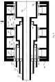
- the Fig. 3 schematically illustrates, in simplified sectional view, an arrangement of a second part of the propeller propulsion system 101, where an arrangement of the electric motors 300 and the coaxial motor shafts 222, 223, 224 in trundle assembly is shown.
- the electric motors 300 are arranged in line. Electric motors 300 are arranged from closest to gearbox 202 to furthest from gearbox 202 in decreasing order of their respective coaxial motor shaft diameters 222, 223, 224.
- Each coaxial motor shaft 222, 223, 224 comprises a coupling portion with a said motor 300.
- this coupling portion is provided with splines or ribs in order to mechanically couple the motor shaft in question with a rotor 301 of said electric motor 300 thanks to a splined ring 303.
- Ball bearings 304 then make it possible to ensure the rotation of the coaxial motor shafts and their respective rotors 301 with respect to a frame or casing 302 in which said electric motors 300 are housed and which is fixed relative to the gearbox 202.
- the portions of said coaxial motor shafts 222, 223, 224 allowing the coupling with the rotors 301 of the electric motors 300 are of the same diameter.
- the coupling with the rotor 301 does not depend on the position of the considered coaxial motor shaft 222, 223, 224 in the pull-out assembly. Strictly identical electric motors 300 can then be used, which simplifies design and maintenance.
- ball bearings 305 are present between two successive coaxial motor shafts. Since these ball bearings are little stressed in nominal operation, a variant consists of replacing them with lubricated plain bearings.
- a loading path can be ensured with a first anchor point on the gearbox 202 and a second anchor point on a part of the frame or casing 302 remote from the gearbox 202 , for example a part of the frame or casing 302 located between the two electric motors 300 farthest from the gearbox 202, as illustrated by the arrow A on the Fig. 3 . This limits the overhang.
- the propeller propulsion system 101 is preferably autonomous in order to simplify its installation and maintenance, as described in the patent document FR3097202A1 or the patent document US 2021/0078719 A1 .
Landscapes
- Engineering & Computer Science (AREA)
- Aviation & Aerospace Engineering (AREA)
- Mechanical Engineering (AREA)
- Connection Of Motors, Electrical Generators, Mechanical Devices, And The Like (AREA)
- Shafts, Cranks, Connecting Bars, And Related Bearings (AREA)
- Automation & Control Theory (AREA)
- Retarders (AREA)
Abstract
Description
- La présente invention concerne un système de propulsion à hélice pour aéronef qui comporte une pluralité de moteurs électriques entraînant conjointement l'hélice en rotation.
- Des moteurs électriques peuvent être utilisés pour entraîner en rotation une hélice de système de propulsion et ainsi déplacer un aéronef tant au sol qu'en vol.
- Les aéronefs commerciaux étant des engins relativement lourds, une grande énergie de propulsion est nécessaire pour les déplacer. Les aéronefs disposent alors typiquement de plusieurs systèmes de propulsion, c'est-à-dire plusieurs moteurs à hélice. Malgré cela, chaque système de propulsion doit typiquement disposer de plusieurs moteurs électriques qui agissent conjointement pour entraîner l'hélice en rotation.
- A cet effet, une boîte à engrenages est utilisée. Chaque moteur électrique comportant un arbre de sortie (arbre moteur), la boîte à engrenages assure l'accouplement mécanique entre les arbres de sortie de ces moteurs électriques et un arbre de sortie de la boîte à engrenages qui est solidaire de l'hélice. La boîte à engrenages comporte ainsi autant d'arbres d'entrée que de moteurs électriques mis en parallèle. Un inconvénient de cet agencement est que, les moteurs étant montés en parallèle, l'encombrement du système de propulsion est important dans le sens de la hauteur et de la largeur. Dit autrement, le diamètre du système de propulsion selon un plan perpendiculaire à l'axe de rotation de l'hélice est élevé. Cela nuit à l'aérodynamisme de l'aéronef et en accroît donc la consommation en carburant (e.g., hydrogène).
- Il est alors souhaitable de fournir une solution qui permette d'améliorer l'aérodynamisme et la consommation de carburant de l'aéronef.
- Il est alors proposé un système de propulsion à hélice pour aéronef comportant : une hélice ; une pluralité de moteurs électriques comportant des arbres moteurs respectifs coaxiaux en montage gigogne ; et une boîte à engrenages ayant un arbre de sortie sur lequel est mécaniquement couplée l'hélice et un arbre d'entrée auquel sont couplés mécaniquement les arbres moteurs coaxiaux desdits moteurs électriques.
- Selon un mode de réalisation particulier, plus un dit arbre moteur coaxial a un diamètre petit, plus cet arbre moteur coaxial pénètre profondément dans la boîte à engrenages.
- Selon un mode de réalisation particulier, les arbres moteurs coaxiaux sont mécaniquement couplés à une cloche solidaire de l'arbre d'entrée de telle sorte que les arbres moteurs coaxiaux et l'arbre d'entrée de la boîte à engrenages partagent un même axe de rotation.
- Selon un mode de réalisation particulier, les arbres moteurs coaxiaux sont mécaniquement couplés à une paroi intérieure de la cloche par le biais d'engrenages respectifs associés à un agencement de roue libre.
- Selon un mode de réalisation particulier, les arbres moteurs coaxiaux présentent des embouts de couplage avec des cannelures ou nervures permettant un assemblage solidaire desdits arbres moteurs coaxiaux avec lesdits engrenages par le biais de bagues cannelées respectives.
- Selon un mode de réalisation particulier, les moteurs électriques sont disposés du plus près de la boîte à engrenages au plus éloigné de la boîte à engrenages selon un ordre décroissant des diamètres de leurs arbres moteurs coaxiaux.
- Selon un mode de réalisation particulier, chaque arbre moteur coaxial comporte une portion de couplage avec un dit moteur qui est munie de cannelures ou de nervures afin de coupler mécaniquement l'arbre moteur coaxial en question avec un rotor dudit moteur électrique grâce à une bague cannelée.
- Selon un mode de réalisation particulier, les portions desdits arbres moteurs coaxiaux permettant le couplage avec les rotors des moteurs électriques sont de même diamètre.
- Selon un mode de réalisation particulier, l'axe de rotation des arbres moteurs coaxiaux est décentré par rapport à l'axe de rotation de l'arbre de sortie, et le système de propulsion à hélice comporte en outre un boîtier de contrôle d'orientation des pales de l'hélice placé dans la continuité de l'arbre de sortie, de l'autre côté de la boîte à engrenages par rapport à l'hélice.
- Il est aussi proposé un aéronef comportant au moins un système de propulsion à hélice tel qu'évoqué ci-dessus dans l'un quelconque de ses modes de réalisation.
- Les caractéristiques de l'invention mentionnées ci-dessus, ainsi que d'autres, apparaîtront plus clairement à la lecture de la description suivante d'au moins un exemple de réalisation, ladite description étant faite en relation avec les dessins joints, parmi lesquels :
- [
Fig. 1 ] illustre schématiquement, en perspective, un aéronef équipé d'au moins un système de propulsion à hélice ; - [
Fig. 2 ] illustre schématiquement, en vue en coupe simplifiée, un agencement d'une première partie d'un tel système de propulsion à hélice ; et - [
Fig. 3 ] illustre schématiquement, en vue en coupe simplifiée, un agencement d'une deuxième partie d'un tel système de propulsion à hélice. - La
Fig. 1 illustre schématiquement, en perspective, un aéronef 100 équipé d'au moins un système de propulsion à hélice 101. De manière illustrative, l'aéronef 100 de laFig. 1 comporte deux systèmes de propulsion à hélice 101 montés respectivement sur chacune des ailes de l'aéronef 100. L'aéronef 100 peut comporter un nombre différent de systèmes de propulsion à hélice 101. - Le terme « longueur » utilisé ici réfère à une dimension horizontale lorsque l'aéronef 100 est au sol, et le terme « hauteur » utilisé ici réfère à une dimension verticale lorsque l'aéronef 100 est au sol.
- La
Fig. 2 illustre schématiquement, en vue en coupe simplifiée, un agencement d'une première partie d'un tel système de propulsion à hélice 101. - Le système de propulsion à hélice 101 comporte une hélice 201 ainsi qu'une boîte à engrenages (« gearbox » en anglais) 202. L'hélice peut être une hélice de turbopropulseur comme schématiquement représenté sur la
Fig. 2 . Toutefois, d'autres configurations d'hélice peuvent être envisagées sans sortir du cadre de l'invention. Ainsi, l'hélice peut par exemple correspondre à une hélice carénée (« ducted fan » en anglais). La boîte à engrenages 202 comporte un arbre de sortie 221 auquel est mécaniquement couplée l'hélice 201. Comme illustré sur laFig. 2 , l'hélice 201 est typiquement montée au bout de l'arbre de sortie 221 de sorte que son axe de rotation est l'axe de révolution 205 de l'arbre de sortie 221. - Le système de propulsion à hélice 101 comporte une pluralité de moteurs électriques 300 (voir
Fig. 3 ) dédiés à la mise en rotation de l'hélice 201 via la boîte à engrenages 202. Par exemple, chaque moteur électrique 300 est alimenté par une ou plusieurs piles à combustible, telles que des piles à hydrogène. - Chaque moteur électrique 300 comporte un arbre moteur et tous les arbres moteurs desdits moteurs électriques 300 sont coaxiaux. Le système de propulsion à hélice 101 comporte, de manière illustrative, trois moteurs électriques 300 et trois arbres moteurs coaxiaux 222, 223, 224 sont ainsi schématiquement représentés sur la
Fig. 2 . - Les arbres moteurs coaxiaux 222, 223, 224 pénètrent dans la boîte à engrenages 202 du côté opposé à celui duquel émerge l'arbre de sortie 221. La boîte à engrenages 202 comporte un ensemble d'engrenages 230, 231 agencés de sorte à assurer une fonction de réduction de vitesse de rotation.
- Les arbres moteurs coaxiaux 222, 223, 224 sont mécaniquement couplés à un même arbre d'entrée 211 de la boîte à engrenages 202. Typiquement, l'arbre d'entrée 211 est équipé de roulements à billes 207 afin d'assurer la libre rotation de l'arbre d'entrée 211 dans la boîte à engrenages 202.
- Les arbres moteurs coaxiaux 222, 223, 224 ont différents diamètres et se logent les uns dans les autres selon un montage gigogne. Ainsi, l'arbre moteur 222 de plus petit diamètre est logé, libre en rotation, dans un corps tubulaire de l'arbre moteur 223 de diamètre immédiatement supérieur, et ainsi de suite.
- Dans un mode de réalisation particulier comme illustré sur la
Fig. 2 , plus un dit arbre moteur coaxial a un diamètre petit, plus cet arbre moteur coaxial pénètre profondément dans la boîte à engrenages 202. Ainsi, l'arbre moteur coaxial 222 pénètre plus profondément dans la boîte à engrenages 202 que l'arbre moteur coaxial 223, qui lui-même pénètre plus profondément dans la boîte à engrenages 202 que l'arbre moteur coaxial 224. Cela permet d'aisément présenter un embout de couplage pour chacun des arbres moteurs coaxiaux 222, 223, 224, afin de réaliser un couplage conjoint des arbres moteurs coaxiaux 222, 223, 224 avec l'arbre d'entrée 211 de la boîte à engrenages 202. - Dans un mode de réalisation particulier, les arbres moteurs coaxiaux 222, 223, 224 sont mécaniquement couplés à une cloche 210 solidaire de l'arbre d'entrée 211 de telle sorte que les arbres moteurs coaxiaux 222, 223, 224 et l'arbre d'entrée 211 de la boîte à engrenages 202 partagent un même axe de rotation 206. Préférentiellement, les arbres moteurs coaxiaux 222, 223, 224 sont mécaniquement couplés à la paroi intérieure de la cloche 210 par le biais d'engrenages respectifs 212, 213, 214 associés à un agencement de roue libre (en prise dans un seul sens de rotation, « freewheel » en anglais) 215. Les embouts de couplage des arbres moteurs coaxiaux 222, 223, 224 peuvent présenter des cannelures ou nervures permettant un assemblage solidaire desdits arbres moteurs coaxiaux 222, 223, 224 avec les engrenages respectifs 212, 213, 214 par le biais de bagues cannelées respectives 216, 217, 218.
- L'axe de rotation 206 des arbres moteurs coaxiaux 222, 223, 224 peut être confondu avec l'axe de rotation 205 de l'arbre de sortie 221 de la boîte à engrenages 202. Toutefois, l'axe de rotation 206 des arbres moteurs coaxiaux 222, 223, 224 est préférentiellement parallèle à l'axe de rotation 205 de l'arbre de sortie 221 et excentré par rapport à l'axe de rotation 205 de l'arbre de sortie 221. Cet agencement est particulièrement avantageux lorsque le système de propulsion à hélice 101 comporte un boîtier 203 incluant un mécanisme de contrôle d'orientation (« pitch control » en anglais) des pales de l'hélice 201. Ainsi, le boîtier 203 est préférentiellement placé dans la continuité de l'arbre de sortie 221, de l'autre côté de la boîte à engrenages 202 par rapport à l'hélice 201, grâce au décentrage entre les axes 205 et 206. Cela permet d'assurer aisément une liaison mécanique 204 entre le boîtier 203 et l'hélice 201 au cœur d'un corps tubulaire de l'arbre de sortie 221. A défaut, le boîtier 203 est placé de sorte à minimiser au possible le décalage entre le boîtier 203 et l'axe 205 de rotation de l'hélice 201.
- La
Fig. 3 illustre schématiquement, en vue en coupe simplifiée, un agencement d'une deuxième partie du système de propulsion à hélice 101, où un agencement des moteurs électriques 300 et des arbres moteurs coaxiaux 222, 223, 224 en montage gigogne est représenté. - Les moteurs électriques 300 sont disposés en ligne. Les moteurs électriques 300 sont disposés du plus près de la boîte à engrenages 202 au plus éloigné de la boîte à engrenages 202 selon un ordre décroissant de leurs diamètres d'arbres moteurs coaxiaux respectifs 222, 223, 224.
- Chaque arbre moteur coaxial 222, 223, 224 comporte une portion de couplage avec un dit moteur 300. Dans un mode de réalisation particulier, cette portion de couplage est munie de cannelures ou de nervures afin de coupler mécaniquement l'arbre moteur en question avec un rotor 301 dudit moteur électrique 300 grâce à une bague cannelée 303. Des roulements à billes 304 permettent alors d'assurer la rotation des arbres moteurs coaxiaux et de leurs rotors respectifs 301 par rapport à un châssis ou carter 302 dans lequel lesdits moteurs électriques 300 sont logés et qui est fixe par rapport à la boîte à engrenages 202.
- Préférentiellement, les portions desdits arbres moteurs coaxiaux 222, 223, 224 permettant le couplage avec les rotors 301 des moteurs électriques 300 sont de même diamètre. Ainsi, le couplage avec le rotor 301 ne dépend pas de la position de l'arbre moteur coaxial considéré 222, 223, 224 dans le montage gigogne. Des moteurs électriques 300 strictement identiques peuvent alors être utilisés, ce qui simplifie la conception et la maintenance.
- De manière à assurer la libre rotation des axes moteurs coaxiaux 222, 223, 224 les uns par rapport aux autres, des roulements à billes 305 sont présents entre deux axes moteurs coaxiaux successifs. Ces roulements à billes étant peu sollicités en fonctionnement nominal, une variante consiste à les remplacer par des paliers lisses (« plain bush » en anglais) lubrifiés.
- D'autres roulements à billes 306 permettent d'assurer la libre rotation de l'ensemble formé par les axes moteurs coaxiaux 222, 223, 224 par rapport au châssis ou carter 302.
- Un trajet de chargement (« loading path » en anglais) peut être assuré avec un premier point d'ancrage sur la boîte à engrenages 202 et un second point d'ancrage sur une partie du châssis ou carter 302 éloignée de la boîte à engrenages 202, par exemple une partie du châssis ou carter 302 située entre les deux moteurs électriques 300 les plus éloignés de la boîte à engrenages 202, comme illustré par la flèche A sur la
Fig. 3 . Cela limite le porte-à-faux. - Le système de propulsion à hélice 101 est préférentiellement autonome afin d'en simplifier l'installation et la maintenance, comme décrit dans le document de brevet
FR3097202A1 US 2021/0078719 A1 .
Claims (9)
- Un système de propulsion à hélice (101) pour aéronef (100) comportant :- une hélice (201) ;- une pluralité de moteurs électriques (300) comportant des arbres moteurs respectifs coaxiaux (222, 223, 224) en montage gigogne ; et- une boîte à engrenages (202) ayant un arbre de sortie (221) sur lequel est mécaniquement couplée l'hélice (201) et un arbre d'entrée auquel sont couplés mécaniquement les arbres moteurs coaxiaux (222, 223, 224) desdits moteurs électriques (300),caractérisé en ce que l'axe de rotation (206) des arbres moteurs coaxiaux (222, 223, 224) est décentré par rapport à l'axe de rotation (205) de l'arbre de sortie, et comporte en outre un boîtier (203) incluant un mécanisme de contrôle d'orientation des pales de l'hélice (201) placé dans la continuité de l'arbre de sortie (221), de l'autre côté de la boîte à engrenages (202) par rapport à l'hélice (201).
- Le système de propulsion à hélice selon la revendication 1, dans lequel plus un dit arbre moteur coaxial (222, 223, 224) a un diamètre petit, plus cet arbre moteur coaxial (222, 223, 224) pénètre profondément dans la boîte à engrenages (202).
- Le système de propulsion à hélice selon la revendication 2, dans lequel les arbres moteurs coaxiaux (222, 223, 224) sont mécaniquement couplés à une cloche (210) solidaire de l'arbre d'entrée (211) de telle sorte que les arbres moteurs coaxiaux (222, 223, 224) et l'arbre d'entrée (211) de la boîte à engrenages (202) partagent un même axe de rotation (206).
- Le système de propulsion à hélice (101) selon la revendication 3, dans lequel les arbres moteurs coaxiaux (222, 223, 224) sont mécaniquement couplés à une paroi intérieure de la cloche (210) par le biais d'engrenages respectifs (212, 213, 214) associés à un agencement de roue libre (215).
- Le système de propulsion à hélice (101) selon la revendication 4, dans lequel les arbres moteurs coaxiaux (222, 223, 224) présentent des embouts de couplage avec des cannelures ou nervures permettant un assemblage solidaire desdits arbres moteurs coaxiaux (222, 223, 224) avec lesdits engrenages (212, 213, 214) par le biais de bagues cannelées respectives (216, 217, 218).
- Le système de propulsion à hélice (101) selon l'une quelconque des revendications 1 à 5, dans lequel les moteurs électriques (300) sont disposés du plus près de la boîte à engrenages (202) au plus éloigné de la boîte à engrenages (202) selon un ordre décroissant des diamètres de leurs arbres moteurs coaxiaux (222, 223, 224).
- Le système de propulsion à hélice (101) selon l'une quelconque des revendications 1 à 6, dans lequel chaque arbre moteur coaxial (222, 223, 224) comporte une portion de couplage avec un dit moteur (300) qui est munie de cannelures ou de nervures afin de coupler mécaniquement l'arbre moteur coaxial (222, 223, 224) en question avec un rotor (301) dudit moteur électrique (300) grâce à une bague cannelée (303).
- Le système de propulsion à hélice (101) selon la revendication 7, dans lequel les portions desdits arbres moteurs coaxiaux (222, 223, 224) permettant le couplage avec les rotors (301) des moteurs électriques (300) sont de même diamètre.
- Un aéronef (100) comportant au moins un système de propulsion à hélice (101) selon l'une quelconque des revendications 1 à 8.
Applications Claiming Priority (1)
| Application Number | Priority Date | Filing Date | Title |
|---|---|---|---|
| FR2107764A FR3125281A1 (fr) | 2021-07-19 | 2021-07-19 | Systeme de propulsion a helice pour aeronef |
Publications (2)
| Publication Number | Publication Date |
|---|---|
| EP4122831A1 true EP4122831A1 (fr) | 2023-01-25 |
| EP4122831B1 EP4122831B1 (fr) | 2024-09-18 |
Family
ID=77519337
Family Applications (1)
| Application Number | Title | Priority Date | Filing Date |
|---|---|---|---|
| EP22185554.7A Active EP4122831B1 (fr) | 2021-07-19 | 2022-07-18 | Système de propulsion à hélice pour aéronef |
Country Status (4)
| Country | Link |
|---|---|
| US (1) | US12486038B2 (fr) |
| EP (1) | EP4122831B1 (fr) |
| CN (1) | CN115636091A (fr) |
| FR (1) | FR3125281A1 (fr) |
Cited By (1)
| Publication number | Priority date | Publication date | Assignee | Title |
|---|---|---|---|---|
| FR3141675A1 (fr) * | 2023-01-30 | 2024-05-10 | Airbus (S.A.S.) | Ensemble de propulsion électrique comportant au moins un moteur électrique présentant un arbre moteur tubulaire, aéronef comportant au moins un tel ensemble de propulsion |
Families Citing this family (6)
| Publication number | Priority date | Publication date | Assignee | Title |
|---|---|---|---|---|
| EP4344028A1 (fr) * | 2022-09-23 | 2024-03-27 | Goodrich Control Systems | Mécanismes de déconnexion |
| EP4343165B1 (fr) * | 2022-09-23 | 2026-04-01 | Hamilton Sundstrand Corporation | Mécanismes de déconnexion |
| EP4406851B1 (fr) | 2023-01-30 | 2025-10-01 | Airbus SAS | Ensemble de propulsion électrique comportant plusieurs moteurs électriques accouplés à un même arbre d'entrée d'un système de transmission, aéronef comportant au moins un tel ensemble de propulsion électrique |
| FR3151573A1 (fr) | 2023-07-24 | 2025-01-31 | Airbus Operations (S.A.S.) | Ensemble de propulsion comprenant au moins un moteur électrique et un système d’accouplement positionnés de part et d’autre d’un système de transmission |
| EP4641886A1 (fr) * | 2024-04-23 | 2025-10-29 | Goodrich Actuation Systems SAS | Moteur électrique à flux axial |
| US12358637B1 (en) | 2024-11-04 | 2025-07-15 | General Electric Company | Air inlet configurations for hybrid aircraft |
Citations (7)
| Publication number | Priority date | Publication date | Assignee | Title |
|---|---|---|---|---|
| JPS621690A (ja) * | 1985-06-27 | 1987-01-07 | Fukashi Uragami | 可変ピツチプロペラ |
| DE102004004480A1 (de) * | 2004-01-26 | 2006-06-22 | Siegfried Pauli | Elektrotriebwerk für den Antrieb koaxialer Wellen von Drehmechanismen |
| US20170190435A1 (en) * | 2014-07-17 | 2017-07-06 | Japan Aerospace Exploration Agency | Motorized Aircraft and Method for Determining Output and Number of Electric Motors in Motorized Aircraft |
| WO2017114245A1 (fr) * | 2015-12-31 | 2017-07-06 | 歌尔科技有限公司 | Véhicule aérien à deux hélices et deux moteurs coaxiaux |
| US20190193835A1 (en) * | 2016-08-31 | 2019-06-27 | FLIR Unmanned Aerial Systems AS | Controlling blade pitch by a plurality of electric motors |
| US20200361622A1 (en) * | 2019-05-16 | 2020-11-19 | Bell Textron Inc. | Dual motor input with overrunning clutch |
| FR3097202A1 (fr) | 2019-06-14 | 2020-12-18 | Airbus | Systeme autonome de propulsion a helice pour un aeronef, ledit systeme autonome de propulsion a helice comportant une pile a combustible |
Family Cites Families (7)
| Publication number | Priority date | Publication date | Assignee | Title |
|---|---|---|---|---|
| FR2830307B1 (fr) * | 2001-10-02 | 2003-12-05 | Eurocopter France | Boite de transmission de puissance basculante a roues a denture frontale peripherique de type "far gear" |
| ES2403329T3 (es) * | 2009-03-02 | 2013-05-17 | Siemens Aktiengesellschaft | Accionamiento de góndola modular para un dispositivo flotante |
| US11731772B2 (en) * | 2017-03-02 | 2023-08-22 | Textron Innovations Inc. | Hybrid propulsion drive train system for tiltrotor aircraft |
| US20190118943A1 (en) * | 2017-10-24 | 2019-04-25 | General Atomics Aeronautical Systems, Inc. | Tail-Sitter Aircraft With Hybrid Propulsion |
| FR3077804B1 (fr) * | 2018-02-09 | 2022-03-18 | Safran | Propulsion hybride pour un aeronef |
| FR3122647A1 (fr) * | 2021-05-04 | 2022-11-11 | Airbus Operations | Système de propulsion pour aéronef comportant un moteur électrique linéaire |
| FR3125280A1 (fr) * | 2021-07-19 | 2023-01-20 | Airbus Operations | Systeme de propulsion a helice pour aeronef |
-
2021
- 2021-07-19 FR FR2107764A patent/FR3125281A1/fr not_active Ceased
-
2022
- 2022-07-15 US US17/865,612 patent/US12486038B2/en active Active
- 2022-07-18 CN CN202210843579.2A patent/CN115636091A/zh active Pending
- 2022-07-18 EP EP22185554.7A patent/EP4122831B1/fr active Active
Patent Citations (8)
| Publication number | Priority date | Publication date | Assignee | Title |
|---|---|---|---|---|
| JPS621690A (ja) * | 1985-06-27 | 1987-01-07 | Fukashi Uragami | 可変ピツチプロペラ |
| DE102004004480A1 (de) * | 2004-01-26 | 2006-06-22 | Siegfried Pauli | Elektrotriebwerk für den Antrieb koaxialer Wellen von Drehmechanismen |
| US20170190435A1 (en) * | 2014-07-17 | 2017-07-06 | Japan Aerospace Exploration Agency | Motorized Aircraft and Method for Determining Output and Number of Electric Motors in Motorized Aircraft |
| WO2017114245A1 (fr) * | 2015-12-31 | 2017-07-06 | 歌尔科技有限公司 | Véhicule aérien à deux hélices et deux moteurs coaxiaux |
| US20190193835A1 (en) * | 2016-08-31 | 2019-06-27 | FLIR Unmanned Aerial Systems AS | Controlling blade pitch by a plurality of electric motors |
| US20200361622A1 (en) * | 2019-05-16 | 2020-11-19 | Bell Textron Inc. | Dual motor input with overrunning clutch |
| FR3097202A1 (fr) | 2019-06-14 | 2020-12-18 | Airbus | Systeme autonome de propulsion a helice pour un aeronef, ledit systeme autonome de propulsion a helice comportant une pile a combustible |
| US20210078719A1 (en) | 2019-06-14 | 2021-03-18 | Airbus Sas | Autonomous propeller propulsion system for an aircraft, said autonomous propeller propulsion system comprising a fuel cell |
Cited By (1)
| Publication number | Priority date | Publication date | Assignee | Title |
|---|---|---|---|---|
| FR3141675A1 (fr) * | 2023-01-30 | 2024-05-10 | Airbus (S.A.S.) | Ensemble de propulsion électrique comportant au moins un moteur électrique présentant un arbre moteur tubulaire, aéronef comportant au moins un tel ensemble de propulsion |
Also Published As
| Publication number | Publication date |
|---|---|
| EP4122831B1 (fr) | 2024-09-18 |
| US20230021085A1 (en) | 2023-01-19 |
| FR3125281A1 (fr) | 2023-01-20 |
| CN115636091A (zh) | 2023-01-24 |
| US12486038B2 (en) | 2025-12-02 |
Similar Documents
| Publication | Publication Date | Title |
|---|---|---|
| EP4122831B1 (fr) | Système de propulsion à hélice pour aéronef | |
| EP4122830B1 (fr) | Systeme de propulsion a hélice pour aeronef | |
| EP4045411B1 (fr) | Système propulsif pour un hélicoptère | |
| EP4067236B1 (fr) | Systeme de propulsion electrique d'un aeronef | |
| EP4291490B1 (fr) | Ensemble propulsif d'aeronef ameliore | |
| CA2941804C (fr) | Relais d'accessoires pour moteur a turbine a gaz | |
| EP3581416A1 (fr) | Dispositif de transmission, notamment pour véhicule électrique | |
| EP3583306B1 (fr) | Système propulsif d'un hélicoptère monomoteur | |
| EP4384726B1 (fr) | Accouplement d'arbres rotatifs permettant un déplacement axial au moyen d'éléments roulants | |
| FR3123264A1 (fr) | Groupe motopropulseur | |
| EP3883854A1 (fr) | Système de propulsion d'un aéronef et procédé de fonctionnement d'un tel système | |
| EP1191259B1 (fr) | Dispositif de lubrification d'une boíte de transmission de puissance présentant une orientation variable, en particulier pour un aéronef convertible à rotors basculants | |
| EP3601747B1 (fr) | Relais d'accessoires pour moteur a turbine a gaz | |
| EP4339104B1 (fr) | Ensemble de propulsion comprenant un système de transmission, plusieurs moteurs électriques et au moins un système d'accouplement déporté, aéronef comprenant au moins un tel ensemble de propulsion | |
| EP4073367A1 (fr) | Groupe auxiliaire de puissance comprenant un générateur de gaz à entrainement direct avec un générateur électrique et un boîtier d'accessoires | |
| EP4411169A1 (fr) | Turbomachine comprenant un reducteur de vitesse et au moins une machine electrique | |
| WO2019110685A1 (fr) | Dispositif de propulsion d'un engin marin de navigation et engin marin de navigation pourvu d'un tel dispositif | |
| WO2023242506A1 (fr) | Train d'engrenages compact pour reducteur de turbomachine | |
| FR3141675A1 (fr) | Ensemble de propulsion électrique comportant au moins un moteur électrique présentant un arbre moteur tubulaire, aéronef comportant au moins un tel ensemble de propulsion | |
| EP4406851B1 (fr) | Ensemble de propulsion électrique comportant plusieurs moteurs électriques accouplés à un même arbre d'entrée d'un système de transmission, aéronef comportant au moins un tel ensemble de propulsion électrique | |
| KR102334533B1 (ko) | 선박 추진장치 | |
| KR102260251B1 (ko) | 선박 추진장치 | |
| FR3123325A1 (fr) | Installation motrice de type modulaire pour un giravion et giravion associé | |
| EP4658917A1 (fr) | Assemblage pour ensemble propulsif d'aeronef avec accouplement debrayable de deux arbres par un manchon d'accouplement a actionnement par fluide pressurise | |
| FR3006734A1 (fr) | Boitier d'entrainement des accessoires pour un turbopropulseur |
Legal Events
| Date | Code | Title | Description |
|---|---|---|---|
| PUAI | Public reference made under article 153(3) epc to a published international application that has entered the european phase |
Free format text: ORIGINAL CODE: 0009012 |
|
| STAA | Information on the status of an ep patent application or granted ep patent |
Free format text: STATUS: THE APPLICATION HAS BEEN PUBLISHED |
|
| AK | Designated contracting states |
Kind code of ref document: A1 Designated state(s): AL AT BE BG CH CY CZ DE DK EE ES FI FR GB GR HR HU IE IS IT LI LT LU LV MC MK MT NL NO PL PT RO RS SE SI SK SM TR |
|
| STAA | Information on the status of an ep patent application or granted ep patent |
Free format text: STATUS: REQUEST FOR EXAMINATION WAS MADE |
|
| 17P | Request for examination filed |
Effective date: 20230720 |
|
| RBV | Designated contracting states (corrected) |
Designated state(s): AL AT BE BG CH CY CZ DE DK EE ES FI FR GB GR HR HU IE IS IT LI LT LU LV MC MK MT NL NO PL PT RO RS SE SI SK SM TR |
|
| GRAP | Despatch of communication of intention to grant a patent |
Free format text: ORIGINAL CODE: EPIDOSNIGR1 |
|
| STAA | Information on the status of an ep patent application or granted ep patent |
Free format text: STATUS: GRANT OF PATENT IS INTENDED |
|
| INTG | Intention to grant announced |
Effective date: 20231129 |
|
| GRAJ | Information related to disapproval of communication of intention to grant by the applicant or resumption of examination proceedings by the epo deleted |
Free format text: ORIGINAL CODE: EPIDOSDIGR1 |
|
| STAA | Information on the status of an ep patent application or granted ep patent |
Free format text: STATUS: REQUEST FOR EXAMINATION WAS MADE |
|
| GRAP | Despatch of communication of intention to grant a patent |
Free format text: ORIGINAL CODE: EPIDOSNIGR1 |
|
| STAA | Information on the status of an ep patent application or granted ep patent |
Free format text: STATUS: GRANT OF PATENT IS INTENDED |
|
| INTC | Intention to grant announced (deleted) | ||
| INTG | Intention to grant announced |
Effective date: 20240415 |
|
| GRAS | Grant fee paid |
Free format text: ORIGINAL CODE: EPIDOSNIGR3 |
|
| GRAA | (expected) grant |
Free format text: ORIGINAL CODE: 0009210 |
|
| STAA | Information on the status of an ep patent application or granted ep patent |
Free format text: STATUS: THE PATENT HAS BEEN GRANTED |
|
| AK | Designated contracting states |
Kind code of ref document: B1 Designated state(s): AL AT BE BG CH CY CZ DE DK EE ES FI FR GB GR HR HU IE IS IT LI LT LU LV MC MK MT NL NO PL PT RO RS SE SI SK SM TR |
|
| REG | Reference to a national code |
Ref country code: GB Ref legal event code: FG4D Free format text: NOT ENGLISH |
|
| REG | Reference to a national code |
Ref country code: CH Ref legal event code: EP |
|
| REG | Reference to a national code |
Ref country code: DE Ref legal event code: R096 Ref document number: 602022006159 Country of ref document: DE |
|
| REG | Reference to a national code |
Ref country code: IE Ref legal event code: FG4D Free format text: LANGUAGE OF EP DOCUMENT: FRENCH |
|
| REG | Reference to a national code |
Ref country code: LT Ref legal event code: MG9D |
|
| PG25 | Lapsed in a contracting state [announced via postgrant information from national office to epo] |
Ref country code: NO Free format text: LAPSE BECAUSE OF FAILURE TO SUBMIT A TRANSLATION OF THE DESCRIPTION OR TO PAY THE FEE WITHIN THE PRESCRIBED TIME-LIMIT Effective date: 20241218 |
|
| PG25 | Lapsed in a contracting state [announced via postgrant information from national office to epo] |
Ref country code: GR Free format text: LAPSE BECAUSE OF FAILURE TO SUBMIT A TRANSLATION OF THE DESCRIPTION OR TO PAY THE FEE WITHIN THE PRESCRIBED TIME-LIMIT Effective date: 20241219 Ref country code: FI Free format text: LAPSE BECAUSE OF FAILURE TO SUBMIT A TRANSLATION OF THE DESCRIPTION OR TO PAY THE FEE WITHIN THE PRESCRIBED TIME-LIMIT Effective date: 20240918 |
|
| PG25 | Lapsed in a contracting state [announced via postgrant information from national office to epo] |
Ref country code: BG Free format text: LAPSE BECAUSE OF FAILURE TO SUBMIT A TRANSLATION OF THE DESCRIPTION OR TO PAY THE FEE WITHIN THE PRESCRIBED TIME-LIMIT Effective date: 20240918 |
|
| PG25 | Lapsed in a contracting state [announced via postgrant information from national office to epo] |
Ref country code: LV Free format text: LAPSE BECAUSE OF FAILURE TO SUBMIT A TRANSLATION OF THE DESCRIPTION OR TO PAY THE FEE WITHIN THE PRESCRIBED TIME-LIMIT Effective date: 20240918 |
|
| PG25 | Lapsed in a contracting state [announced via postgrant information from national office to epo] |
Ref country code: HR Free format text: LAPSE BECAUSE OF FAILURE TO SUBMIT A TRANSLATION OF THE DESCRIPTION OR TO PAY THE FEE WITHIN THE PRESCRIBED TIME-LIMIT Effective date: 20240918 |
|
| REG | Reference to a national code |
Ref country code: NL Ref legal event code: MP Effective date: 20240918 |
|
| PG25 | Lapsed in a contracting state [announced via postgrant information from national office to epo] |
Ref country code: RS Free format text: LAPSE BECAUSE OF FAILURE TO SUBMIT A TRANSLATION OF THE DESCRIPTION OR TO PAY THE FEE WITHIN THE PRESCRIBED TIME-LIMIT Effective date: 20241218 |
|
| PG25 | Lapsed in a contracting state [announced via postgrant information from national office to epo] |
Ref country code: RS Free format text: LAPSE BECAUSE OF FAILURE TO SUBMIT A TRANSLATION OF THE DESCRIPTION OR TO PAY THE FEE WITHIN THE PRESCRIBED TIME-LIMIT Effective date: 20241218 Ref country code: NO Free format text: LAPSE BECAUSE OF FAILURE TO SUBMIT A TRANSLATION OF THE DESCRIPTION OR TO PAY THE FEE WITHIN THE PRESCRIBED TIME-LIMIT Effective date: 20241218 Ref country code: LV Free format text: LAPSE BECAUSE OF FAILURE TO SUBMIT A TRANSLATION OF THE DESCRIPTION OR TO PAY THE FEE WITHIN THE PRESCRIBED TIME-LIMIT Effective date: 20240918 Ref country code: HR Free format text: LAPSE BECAUSE OF FAILURE TO SUBMIT A TRANSLATION OF THE DESCRIPTION OR TO PAY THE FEE WITHIN THE PRESCRIBED TIME-LIMIT Effective date: 20240918 Ref country code: GR Free format text: LAPSE BECAUSE OF FAILURE TO SUBMIT A TRANSLATION OF THE DESCRIPTION OR TO PAY THE FEE WITHIN THE PRESCRIBED TIME-LIMIT Effective date: 20241219 Ref country code: FI Free format text: LAPSE BECAUSE OF FAILURE TO SUBMIT A TRANSLATION OF THE DESCRIPTION OR TO PAY THE FEE WITHIN THE PRESCRIBED TIME-LIMIT Effective date: 20240918 Ref country code: BG Free format text: LAPSE BECAUSE OF FAILURE TO SUBMIT A TRANSLATION OF THE DESCRIPTION OR TO PAY THE FEE WITHIN THE PRESCRIBED TIME-LIMIT Effective date: 20240918 |
|
| REG | Reference to a national code |
Ref country code: AT Ref legal event code: MK05 Ref document number: 1724503 Country of ref document: AT Kind code of ref document: T Effective date: 20240918 |
|
| PG25 | Lapsed in a contracting state [announced via postgrant information from national office to epo] |
Ref country code: NL Free format text: LAPSE BECAUSE OF FAILURE TO SUBMIT A TRANSLATION OF THE DESCRIPTION OR TO PAY THE FEE WITHIN THE PRESCRIBED TIME-LIMIT Effective date: 20240918 |
|
| PG25 | Lapsed in a contracting state [announced via postgrant information from national office to epo] |
Ref country code: IS Free format text: LAPSE BECAUSE OF FAILURE TO SUBMIT A TRANSLATION OF THE DESCRIPTION OR TO PAY THE FEE WITHIN THE PRESCRIBED TIME-LIMIT Effective date: 20250118 Ref country code: PT Free format text: LAPSE BECAUSE OF FAILURE TO SUBMIT A TRANSLATION OF THE DESCRIPTION OR TO PAY THE FEE WITHIN THE PRESCRIBED TIME-LIMIT Effective date: 20250120 |
|
| PG25 | Lapsed in a contracting state [announced via postgrant information from national office to epo] |
Ref country code: RO Free format text: LAPSE BECAUSE OF FAILURE TO SUBMIT A TRANSLATION OF THE DESCRIPTION OR TO PAY THE FEE WITHIN THE PRESCRIBED TIME-LIMIT Effective date: 20240918 Ref country code: SM Free format text: LAPSE BECAUSE OF FAILURE TO SUBMIT A TRANSLATION OF THE DESCRIPTION OR TO PAY THE FEE WITHIN THE PRESCRIBED TIME-LIMIT Effective date: 20240918 |
|
| PG25 | Lapsed in a contracting state [announced via postgrant information from national office to epo] |
Ref country code: ES Free format text: LAPSE BECAUSE OF FAILURE TO SUBMIT A TRANSLATION OF THE DESCRIPTION OR TO PAY THE FEE WITHIN THE PRESCRIBED TIME-LIMIT Effective date: 20240918 |
|
| PG25 | Lapsed in a contracting state [announced via postgrant information from national office to epo] |
Ref country code: AT Free format text: LAPSE BECAUSE OF FAILURE TO SUBMIT A TRANSLATION OF THE DESCRIPTION OR TO PAY THE FEE WITHIN THE PRESCRIBED TIME-LIMIT Effective date: 20240918 Ref country code: EE Free format text: LAPSE BECAUSE OF FAILURE TO SUBMIT A TRANSLATION OF THE DESCRIPTION OR TO PAY THE FEE WITHIN THE PRESCRIBED TIME-LIMIT Effective date: 20240918 |
|
| PG25 | Lapsed in a contracting state [announced via postgrant information from national office to epo] |
Ref country code: CZ Free format text: LAPSE BECAUSE OF FAILURE TO SUBMIT A TRANSLATION OF THE DESCRIPTION OR TO PAY THE FEE WITHIN THE PRESCRIBED TIME-LIMIT Effective date: 20240918 Ref country code: PL Free format text: LAPSE BECAUSE OF FAILURE TO SUBMIT A TRANSLATION OF THE DESCRIPTION OR TO PAY THE FEE WITHIN THE PRESCRIBED TIME-LIMIT Effective date: 20240918 |
|
| PG25 | Lapsed in a contracting state [announced via postgrant information from national office to epo] |
Ref country code: SK Free format text: LAPSE BECAUSE OF FAILURE TO SUBMIT A TRANSLATION OF THE DESCRIPTION OR TO PAY THE FEE WITHIN THE PRESCRIBED TIME-LIMIT Effective date: 20240918 Ref country code: IT Free format text: LAPSE BECAUSE OF FAILURE TO SUBMIT A TRANSLATION OF THE DESCRIPTION OR TO PAY THE FEE WITHIN THE PRESCRIBED TIME-LIMIT Effective date: 20240918 |
|
| REG | Reference to a national code |
Ref country code: DE Ref legal event code: R097 Ref document number: 602022006159 Country of ref document: DE |
|
| PG25 | Lapsed in a contracting state [announced via postgrant information from national office to epo] |
Ref country code: DK Free format text: LAPSE BECAUSE OF FAILURE TO SUBMIT A TRANSLATION OF THE DESCRIPTION OR TO PAY THE FEE WITHIN THE PRESCRIBED TIME-LIMIT Effective date: 20240918 |
|
| PLBE | No opposition filed within time limit |
Free format text: ORIGINAL CODE: 0009261 |
|
| STAA | Information on the status of an ep patent application or granted ep patent |
Free format text: STATUS: NO OPPOSITION FILED WITHIN TIME LIMIT |
|
| 26N | No opposition filed |
Effective date: 20250619 |
|
| PG25 | Lapsed in a contracting state [announced via postgrant information from national office to epo] |
Ref country code: SE Free format text: LAPSE BECAUSE OF FAILURE TO SUBMIT A TRANSLATION OF THE DESCRIPTION OR TO PAY THE FEE WITHIN THE PRESCRIBED TIME-LIMIT Effective date: 20240918 |
|
| PGFP | Annual fee paid to national office [announced via postgrant information from national office to epo] |
Ref country code: DE Payment date: 20250722 Year of fee payment: 4 |
|
| PGFP | Annual fee paid to national office [announced via postgrant information from national office to epo] |
Ref country code: FR Payment date: 20250725 Year of fee payment: 4 |
|
| REG | Reference to a national code |
Ref country code: CH Ref legal event code: H13 Free format text: ST27 STATUS EVENT CODE: U-0-0-H10-H13 (AS PROVIDED BY THE NATIONAL OFFICE) Effective date: 20260224 |
|
| PG25 | Lapsed in a contracting state [announced via postgrant information from national office to epo] |
Ref country code: LU Free format text: LAPSE BECAUSE OF NON-PAYMENT OF DUE FEES Effective date: 20250718 |
|
| REG | Reference to a national code |
Ref country code: BE Ref legal event code: MM Effective date: 20250731 |
|
| PG25 | Lapsed in a contracting state [announced via postgrant information from national office to epo] |
Ref country code: BE Free format text: LAPSE BECAUSE OF NON-PAYMENT OF DUE FEES Effective date: 20250731 |
|
| PG25 | Lapsed in a contracting state [announced via postgrant information from national office to epo] |
Ref country code: CH Free format text: LAPSE BECAUSE OF NON-PAYMENT OF DUE FEES Effective date: 20250731 |