EP4122818B1 - System zur steuerung einer flugsteuerfläche - Google Patents
System zur steuerung einer flugsteuerfläche Download PDFInfo
- Publication number
- EP4122818B1 EP4122818B1 EP21290049.2A EP21290049A EP4122818B1 EP 4122818 B1 EP4122818 B1 EP 4122818B1 EP 21290049 A EP21290049 A EP 21290049A EP 4122818 B1 EP4122818 B1 EP 4122818B1
- Authority
- EP
- European Patent Office
- Prior art keywords
- ema
- mode
- emas
- blocked
- active
- Prior art date
- Legal status (The legal status is an assumption and is not a legal conclusion. Google has not performed a legal analysis and makes no representation as to the accuracy of the status listed.)
- Active
Links
Images
Classifications
-
- B—PERFORMING OPERATIONS; TRANSPORTING
- B64—AIRCRAFT; AVIATION; COSMONAUTICS
- B64C—AEROPLANES; HELICOPTERS
- B64C13/00—Control systems or transmitting systems for actuating flying-control surfaces, lift-increasing flaps, air brakes, or spoilers
- B64C13/24—Transmitting means
- B64C13/38—Transmitting means with power amplification
- B64C13/50—Transmitting means with power amplification using electrical energy
- B64C13/505—Transmitting means with power amplification using electrical energy having duplication or stand-by provisions
Definitions
- EMAs electromechanical actuators
- EMA electromechanical actuator
- a controller may be configured to be in communication with both the locking device and the actuator. The controller may monitor a position of the actuator during flight and react when it is detected that the actuator has not moved for a set amount of time.
- a plurality of actuators may be attached to one or more summing levers, each having an actuator output point that is attached to the flight control surface.
- US 2019/270511 A1 describes EMA thermal management optimization, wherein a system for controlling an electromechanical actuator of an aircraft includes a locking device configured to mechanically lock said actuator in a first fixed position and to mechanically unlock said actuator from said first fixed position and a controller configured to be in bi-directional communication with both said locking device and said actuator.
- the controller is configured to monitor a position of said actuator during flight and to detect when said actuator has not moved for a set amount of time, said controller further being configured to instruct said locking device to lock said actuator in said first, locked position when said set time has been reached.
- a method for controlling the thermal properties of an electromechanical actuator of an aircraft is provided.
- US 2019/291850 A1 describes trailing edge wing flap systems.
- US 2002/116096 A1 describes a method and device for controlling an aircraft maneuvering component.
- US 2019/233087 A1 describes the autonomous reconfiguration of a multi-redundant actuator control system.
- a system for controlling a flight control surface is described herein and defined in claim 1.
- both of the first and second EMAs are operating in said active mode.
- said first and second EMAs are connected to the flight control surface that is being controlled.
- the first and second EMAs are each connected to a flight control computer (FCC).
- FCC flight control computer
- said first and second EMAs are provided in a housing and wherein, in the event that a temperature of said housing reaches an upper threshold, the system is configured to operate with both the first and the second EMAs in said blocked/blocked mode.
- the system in the event that either one or both the first and second EMAs fail, is configured to switch the first and second EMAs into said blocked/blocked mode.
- a method for controlling a flight control surface is also described herein, and defined in claim 7.
- the method comprises in normal operation, controlling said flight control surface by operating both of the first and second EMAs in said active mode.
- said first and second EMAs are provided in a housing and in the event that a temperature of said housing reaches an upper threshold, the flight surface is controlled with both the first and the second EMAs in said blocked/blocked mode.
- the flight surface is controlled with the first and second EMAs being held in said blocked/blocked mode.
- EMAs electromechanical actuators
- Figure 1 depicts a known design 100 for the movement of a flight control surface.
- the known design comprises a first EHSA 110 and associated Remote Electronic Unit (REU) 20 and a second EHSA 130 and associated REU 140.
- Each of these REUs 120, 140 are connected to the flight control computers (FCCs) 150 and each of the EHSAs 110, 130 are connected to the flight control surface 160.
- FCCs flight control computers
- these known systems have EHSs that act in two modes - Active or Damped.
- one e.g. the first EHSA 110 is active, controlling the position of the flight control surface 160 and reacting to the full surface hinge moment, while the adjacent, i.e. second EHSA 130 remains in damped mode.
- the system switches the first EHSA 110 into the damped mode and the adjacent, or second EHSA 130, switches into active mode. The system then operates as previously.
- this electric system architecture (which is replicating the conventional hydraulic system architecture) leads to a very bulky EMA system which is sized to react to the full surface hinge moment and the drag generated by the motion of the adjacent actuator in damped mode.
- Such systems are twice as large as their equivalent EHSA and need to dissipate locally the heat generated (copper losses) by reacting external loads.
- the new examples described herein and with reference to figures 2 to 4 allow the EMAs to introduce a third mode, which is an anti-extension or blocked mode into the EMA design.
- This third, anti-extension or blocked mode is controlled in use by the adjacent actuator.
- the new examples described herein improve the remaining thermal management in case of an adjacent EMA failure, which will react to a surface full hinge moment. They also reduce aerodynamic drag in case of a dual EMA failure (such that there is no free float).
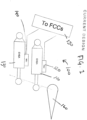
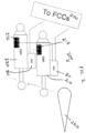
- a new example of a new type of system 200 for controlling a flight surface 260 is shown in figure 2 .
- a first EMA 210 is provided which comprises an associated first Motor Drive Electronics (MDE) 211 and a first solenoid 212.
- the system further comprises a second EMA 220 which comprises an associated second MDE 221 and a second solenoid 222.
- MDE Motor Drive Electronics
- each of the first and second EMAs 210, 220 are connected to the flight control surface 260.
- the first and second EMAs 210, 220 as well as their associated MDEs 211, 221 are each connected to the flight control computers (FCCs) 270.
- FCCs flight control computers
- the FCCs may be considered to correspond to the "brain" of the system (i.e., the master), whereas the MDEs/actuators (EMAs) are the slaves in that they respond to the orders sent from the FCCs and report the EMA health status.
- the first solenoid 212 of the first EMA 210 is further connected to the second MDE 221 of the second EMA 220 and the second solenoid 222 of the second EMA 220 is connected to the first MDE 211 of the first EMA 210. Due to this arrangement the solenoid 212, 222 of each EMA 210, 220 can be activated by the adjacent EMA 210, 220 (in this example, via the MDE of the adjacent EMA).
- This new system is able to work in three modes, i.e. in 1) an active/active mode, wherein both the EMAs 210, 220 are in the active mode, 2) an active/stand-by mode, wherein one of the EMAs 210, 220 is in the active mode and the other is in the stand-by mode, or 3) a blocked/blocked mode, wherein both the EMAs 210, 220 are in the blocked mode.
- the blocked mode can be replaced with an anti-extension mode if required (e.g. for an aileron application).
- both EMAs 210, 220 are electrically supplied by aircraft high and low power networks. Both EMAs 210, 220 receive a signal from the FCCs to switch into the active mode (each MDE activates its own EMA solenoid and adjacent EMA solenoid). Both EMAs 210, 220 receive the same position order from the FCCs to control the flight control surface position. The EMAs may exchange information in order to alleviate the force flight generated between the two actuators connected to the same surface (the force fight is usually generated by the control loop difference/error between the two channels through surface structural stiffness).
- At least one EMA 210, 220 is electrically supplied by aircraft high and low power networks.
- the adjacent EMA 210, 220 may or may not be electrically supplied by aircraft high and low power networks, that is, it can be alive and functioning normally, or failed, the same goes for its FCC.
- the EMA 210, 220 which is electrically supplied also receives a signal from its FCC to switch into the active mode (the MDE activates its own EMA solenoid and adjacent EMA solenoid).
- the EMA 210, 220 which is electrically supplied also receives a position order from its FCC to control the flight control surface position.
- the Adjacent EMA 210, 220 which is still connected to the flight control surface is back driven by the active EMA 210, 220.
- both EMAs may be, or may not be, electrically supplied by aircraft high and low power networks. Both EMAs may or may not receive a signal from FCCs to switch into the blocked mode (when not electrically energized, the solenoids switch naturally into the blocked mode). The flight control surface is blocked in a given position.
- the adjacent, second EMA 220 (which is still operating normally in the active mode) is configured to unlock the failed, first EMA 210 by energizing the solenoid 212 of the first EMA 210.
- the system is therefore now in an active/stand-by configuration.
- the remaining active EMA i.e. the second EMA 220, then controls the surface position and reacts electromechanically to the full surface hinge moment.
- Both EMAs 210, 220 may be positioned within a housing (not shown). In the event that the housing temperature reaches a specified upper limit, both the first and the second EMAs 210, 220 can be switched into blocking mode (i.e. the blocked/blocked mode). The flight control surface 260 is then in a blocked position and the surface hinge moment is reacted mechanically by the first and second EMAs 210, 220.
- the EMA that has not failed can then cool down and when the EMA housing temperature reaches a given lower value or threshold, the system can be reconfigured into the Active/stand-by arrangement.
- first and second actuators 210, 220 fail, the first and second actuators are switched into blocked mode, thereby avoiding surface free float and associated drag penalty.
- the architecture of the new systems described herein and depicted in figure 2 reduces the size of the EMA for thin wing applications.
- the EMA system can be sized for only a percentage of the full hinge moment (higher than 50%) and does not generate any damping in case of failure.
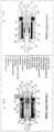
- FIG. 3 shows the components of a current EMA design.
- the current EMA design comprises an actuator body 1, having an attachment bearing 2 at a first longitudinal end and a roller bearing 3 at the opposite longitudinal end.
- the roller bearing 3 is connected to the actuator rod 4, which in turn is connected to a linear position transducer 12.
- a sealing system 11 is provided between the actuator rod 4 and the actuator body 1.
- a motor stator 8 internal to the actuator body 1 and a motor rotor 7 provide torque to a ball or a roller screw nut 5 which interacts with balls or rollers 6 which are positioned externally to the actuator rod 4.
- a linear position transducer 12 provides actuator rod 4 position to the actuator control electronic.
- a trust bearing 9 is provided externally to the ball or roller screw nut 6.
- An angular position sensor 13 is provided to measure the angle of the rotor of the electric motor.
- An end stop 14 is provided to limit the movement of the actuator rod 4, as well as an anti-rotation device 15 which prevents rotation of the actuator rod 4.
- a ball bearing 10 is also provided around the actuator rod 4 to guide the motor rotor 7.
- Figure 4 shows the inner workings of new EMA design that can be used in the system 200 shown in figure 2 , which has many of the same features as that shown in figure 3 , but additionally has a pawl 16, a solenoid 17 and a ratchet wheel 18.
- This allows the EMA to work in three modes with an anti-extension device as described above with reference to figure 2 .
- the solenoid 17 When the solenoid 17 is energized, it disengages the pawl 16 from the ratchet wheel 18 and thus enabling the ball screw or roller screw nut 5 to rotate and the actuator rod 4 to translate in both directions under external load application.
- the solenoid 17 When the solenoid 17 is de-energized, the pawl 16 engages into a teeth of the ratchet wheel 18 and prevents the rotation of the ball or roller screw nut 5 and the translation of the actuator rod in the extension direction.
- the linear EMA could also/alternatively be replaced by a rotary EMA using a gearbox and an output lever connected to the rotary output of the gearbox.
- the anti-extension (unidirectional blocking) mode could also be replaced by a blocked mode (bi-directional).
- the ratchet wheel and the pawl could alternatively/also be replaced by a unidirectional free wheel (anti-extension mode) or by friction discs (a stator and a rotor driven by a solenoid) for the blocked mode configuration.
Landscapes
- Engineering & Computer Science (AREA)
- Automation & Control Theory (AREA)
- Aviation & Aerospace Engineering (AREA)
- Transmission Devices (AREA)
- Control Of Position, Course, Altitude, Or Attitude Of Moving Bodies (AREA)
Claims (10)
- System zur Steuerung einer Flugsteuerfläche (260), wobei das System Folgendes umfasst:einen ersten elektromechanischen Aktuator "EMA" (210), und dadurch gekennzeichnet, dass es ferner einen zweiten EMA (220) umfasst, die jeweils mit der Flugsteuerfläche (260) verbunden sind;und wobei jeder EMA (210, 220) dazu konfiguriert ist, in drei Modi angeordnet zu sein und zwischen diesen umgeschaltet zu werden;wobei die drei Modi Folgendes umfassen:einen Aktivmodus, einen Standby-Modus und einen Sperr- oder Anti-Erweiterungsmodus, undwobei der erste EMA (210) eine erste Motorantriebselektronik "MDE" (211) und einen ersten Elektromagneten (212) umfasst, und wobei der zweite EMA (220) eine zweite MDE (221) und einen zweiten Elektromagneten (222) umfasst;wobei die zweite MDE (221) des zweiten EMA (220) mit dem ersten Elektromagneten (212) des ersten EMA (210) verbunden ist;wobei die erste MDE (221) des ersten EMA (210) mit dem zweiten Elektromagneten (222) des zweiten EMA (220) verbunden ist;und wobei das System dazu konfiguriert ist, in Folgendem betreibbar zu sein und dazwischen umschaltbar zu sein:einem Aktiv/Aktivmodus, wobei sich sowohl der erste als auch der zweite EMA (210, 220) in dem Aktivmodus befinden;einem Aktiv/Standby-Modus, wobei sich der erste EMA (210) in dem Aktivmodus und der zweite EMA (220) in dem Standby-Modus befindet; undeinem Sperr-/Sperrmodus oder Anti-Erweiterungs-/Anti-Erweiterungsmodus, wobei sich beide EMAs (210, 220) in einem Sperr- oder Anti-Erweiterungsmodus befinden,und wobei ferner, in dem Falle eines Ausfalls des ersten EMA (210), der zweite EMA (220) dazu konfiguriert ist, den ersten EMA (210) durch Aktivieren des Elektromagnets (212) des ersten EMA (210) zu entriegeln und dadurch das System in den Aktiv/Standby-Modus umzuschalten.
- System nach einem der vorhergehenden Ansprüche, wobei sowohl der erste als auch der zweite EMA (210, 220) bei Normalbetrieb in dem Aktivmodus arbeiten.
- System nach einem der vorhergehenden Ansprüche, wobei der erste und der zweite EMA (210, 220) mit der Flugsteuerfläche (260) verbunden sind, die gesteuert wird.
- System nach einem der vorhergehenden Ansprüche, wobei der erste und der zweite EMA (210, 220) jeweils mit einem Flugsteuercomputer "FCC" (270) verbunden sind.
- System nach einem der Ansprüche 2 bis 4, wobei der erste und der zweite EMA (210, 220) in einem Gehäuse bereitgestellt sind und wobei das System in dem Falle, dass eine Temperatur des Gehäuses einen oberen Schwellenwert erreicht, dazu konfiguriert ist, sowohl mit dem ersten als auch mit dem zweiten EMA (210, 220) in dem Sperr-/Sperrmodus zu arbeiten.
- System nach einem der Ansprüche 2 bis 5, wobei in dem Falle, dass entweder einer oder beide des ersten und des zweiten EMA (210, 220) ausfallen, das System dazu konfiguriert ist, den ersten und den zweiten EMA (210, 220) in den Sperr-/Sperrmodus umzuschalten.
- Verfahren zum Steuern einer Flugsteuerfläche (260), umfassend Bereitstellen eines ersten elektromechanischen Aktuators "EMA" (210) und dadurch gekennzeichnet, dass es ferner einen zweiten EMA (220) umfasst, wobei jeder des ersten und des zweiten EMA mit der Flugsteuerfläche (260) verbunden ist;wobei jeder EMA (210, 220) dazu konfiguriert ist, in drei Modi angeordnet und zwischen diesen umgeschaltet zu werden; wobei die drei Modi Folgendes umfassen: einen Aktivmodus, einen Standby-Modus und einen Sperr- oder Anti-Erweiterungsmodus, und Steuern der Flugsteuerfläche durch Umschalten zwischen und Betreiben der EMAs in einem Aktiv/Aktivmodus, wobei sich sowohl der erste als auch der zweite EMA (210, 220) in dem Aktivmodus befinden;einen Aktiv/Standby-Modus, wobei sich der erste EMA (210) in dem Aktivmodus und der zweite EMA (220) in dem Standby-Modus befindet; undeinen Sperr-/Sperrmodus oder Anti-Erweiterungs-/Anti-Erweiterungsmodus, wobei sich beide EMAs (210, 220) in einem Sperr- oder Anti-Erweiterungsmodus befinden, undwobei der erste EMA (210) eine erste Motorantriebselektronik "MDE" (211) und einen ersten Elektromagneten (212) umfasst und der zweite EMA (220) eine zweite MDE (221) und einen zweiten Elektromagneten (222) umfasst;wobei die zweite MDE (221) des zweiten EMA (220) mit dem ersten Elektromagneten (212) des ersten EMA (210) verbunden ist;wobei die erste MDE (221) des ersten EMA (210) mit dem zweiten Elektromagneten (222) des zweiten EMA (220) verbunden ist;und ferner umfassend, in dem Falle eines Ausfalls des ersten EMA (210), Betreiben der Flugsteuerfläche durch den zweiten EMA (220), der den ersten EMA (210) über den ersten Elektromagneten (212) entriegelt, da der zweite EMA (220) den Elektromagneten (212) des ersten EMA (210) aktiviert und dadurch das System in den Aktiv/Standby-Modus umschaltet.
- Verfahren nach Anspruch 7, umfassend, bei Normalbetrieb, Steuern der Flugsteuerfläche durch Betreiben sowohl des ersten als auch des zweiten EMA (210, 220) in dem Aktivmodus.
- Verfahren nach einem der Ansprüche 7 oder 8, wobei der erste und der zweite EMA (210, 220) in einem Gehäuse bereitgestellt sind, und wobei in dem Falle, dass eine Temperatur des Gehäuses einen oberen Schwellenwert erreicht, Steuern der Flugfläche sowohl mit dem ersten als auch mit dem zweiten EMA (210, 220) in dem Sperr-/Sperrmodus.
- Verfahren nach einem der Ansprüche 7 bis 9, wobei in dem Falle, dass einer oder beide des ersten und des zweiten EMA (210, 220) ausfällt, Steuern der Flugfläche mit dem ersten und dem zweiten EMA (210, 220) in dem Sperr-/Sperrmodus gehalten wird.
Priority Applications (4)
| Application Number | Priority Date | Filing Date | Title |
|---|---|---|---|
| EP21290049.2A EP4122818B1 (de) | 2021-07-19 | 2021-07-19 | System zur steuerung einer flugsteuerfläche |
| CA3161032A CA3161032A1 (en) | 2021-07-19 | 2022-05-30 | System for controlling a flight control surface |
| US17/858,224 US12037102B2 (en) | 2021-07-19 | 2022-07-06 | System for controlling a flight control surface |
| BR102022013470-7A BR102022013470A2 (pt) | 2021-07-19 | 2022-07-06 | Sistema e método para controlar uma superfície de controle de voo |
Applications Claiming Priority (1)
| Application Number | Priority Date | Filing Date | Title |
|---|---|---|---|
| EP21290049.2A EP4122818B1 (de) | 2021-07-19 | 2021-07-19 | System zur steuerung einer flugsteuerfläche |
Publications (2)
| Publication Number | Publication Date |
|---|---|
| EP4122818A1 EP4122818A1 (de) | 2023-01-25 |
| EP4122818B1 true EP4122818B1 (de) | 2025-01-08 |
Family
ID=77274756
Family Applications (1)
| Application Number | Title | Priority Date | Filing Date |
|---|---|---|---|
| EP21290049.2A Active EP4122818B1 (de) | 2021-07-19 | 2021-07-19 | System zur steuerung einer flugsteuerfläche |
Country Status (4)
| Country | Link |
|---|---|
| US (1) | US12037102B2 (de) |
| EP (1) | EP4122818B1 (de) |
| BR (1) | BR102022013470A2 (de) |
| CA (1) | CA3161032A1 (de) |
Families Citing this family (1)
| Publication number | Priority date | Publication date | Assignee | Title |
|---|---|---|---|---|
| USD1098227S1 (en) * | 2024-05-01 | 2025-10-14 | Ruben Leon | Servo motor |
Family Cites Families (9)
| Publication number | Priority date | Publication date | Assignee | Title |
|---|---|---|---|---|
| FR2811780B1 (fr) * | 2000-07-13 | 2002-08-30 | Aerospatiale Matra Airbus | Procede et dispositif de commande d'organes de manoeuvre d'un aeronef, a modules de secours electriques |
| US6776376B2 (en) | 2002-10-18 | 2004-08-17 | Hamilton Sunstrand | Flight control surface actuation system |
| US8136418B2 (en) | 2007-02-07 | 2012-03-20 | Parker-Hannifin Corporation | Electromechanical actuating assembly |
| FR3058983B1 (fr) * | 2016-11-22 | 2018-11-02 | Safran Electronics & Defense | Actionneur a montage facilite |
| US10843792B2 (en) * | 2018-02-01 | 2020-11-24 | Hamilton Sundstrand Corporation | Autonomous reconfiguration of a multi-redundant actuator control system |
| EP3533707B1 (de) * | 2018-03-01 | 2020-06-24 | Goodrich Actuation Systems SAS | Thermische ema-verwaltungsoptimierung |
| US10882603B2 (en) * | 2018-03-20 | 2021-01-05 | The Boeing Company | Distributed trailing edge wing flap systems |
| FR3113888A1 (fr) * | 2020-09-09 | 2022-03-11 | Eaton Intelligent Power Limited | Système de synchronisation d'actionnement de gouverne |
| EP4029776A1 (de) * | 2021-01-18 | 2022-07-20 | Goodrich Actuation Systems SAS | Aktuatorsteuerung zur kraftkonflikt-abschwächung |
-
2021
- 2021-07-19 EP EP21290049.2A patent/EP4122818B1/de active Active
-
2022
- 2022-05-30 CA CA3161032A patent/CA3161032A1/en active Pending
- 2022-07-06 US US17/858,224 patent/US12037102B2/en active Active
- 2022-07-06 BR BR102022013470-7A patent/BR102022013470A2/pt unknown
Also Published As
| Publication number | Publication date |
|---|---|
| US20230013360A1 (en) | 2023-01-19 |
| BR102022013470A2 (pt) | 2023-03-07 |
| EP4122818A1 (de) | 2023-01-25 |
| CA3161032A1 (en) | 2023-01-19 |
| US12037102B2 (en) | 2024-07-16 |
Similar Documents
| Publication | Publication Date | Title |
|---|---|---|
| US10538310B2 (en) | Near synchronous distributed hydraulic motor driven actuation system | |
| CN104619590B (zh) | 控制表面驱动组件 | |
| EP2543589B1 (de) | Primäre Flugsteuerungen | |
| EP2415669B1 (de) | Steuersystem | |
| EP3549857B1 (de) | Klappestellantriebssystem | |
| EP3631243B1 (de) | Fehlertoleranter elektromechanischer linearantrieb | |
| EP3533707B1 (de) | Thermische ema-verwaltungsoptimierung | |
| US11235862B2 (en) | Aircraft flight control system including electromechanical actuator | |
| EP1927543B1 (de) | Elektromechanischer Linearantrieb | |
| EP4122818B1 (de) | System zur steuerung einer flugsteuerfläche | |
| EP1921347A2 (de) | Einzelantriebbetätigungssystem mit Redundanzen und Sicherheitsvorrichtung | |
| EP4660076A1 (de) | Aktuatoranordnungsarchitektur | |
| CN118107779A (zh) | 阻挡单元、机电单元和飞行器 |
Legal Events
| Date | Code | Title | Description |
|---|---|---|---|
| PUAI | Public reference made under article 153(3) epc to a published international application that has entered the european phase |
Free format text: ORIGINAL CODE: 0009012 |
|
| STAA | Information on the status of an ep patent application or granted ep patent |
Free format text: STATUS: THE APPLICATION HAS BEEN PUBLISHED |
|
| AK | Designated contracting states |
Kind code of ref document: A1 Designated state(s): AL AT BE BG CH CY CZ DE DK EE ES FI FR GB GR HR HU IE IS IT LI LT LU LV MC MK MT NL NO PL PT RO RS SE SI SK SM TR |
|
| STAA | Information on the status of an ep patent application or granted ep patent |
Free format text: STATUS: REQUEST FOR EXAMINATION WAS MADE |
|
| 17P | Request for examination filed |
Effective date: 20230725 |
|
| RBV | Designated contracting states (corrected) |
Designated state(s): AL AT BE BG CH CY CZ DE DK EE ES FI FR GB GR HR HU IE IS IT LI LT LU LV MC MK MT NL NO PL PT RO RS SE SI SK SM TR |
|
| GRAP | Despatch of communication of intention to grant a patent |
Free format text: ORIGINAL CODE: EPIDOSNIGR1 |
|
| RIC1 | Information provided on ipc code assigned before grant |
Ipc: G05D 1/00 20060101ALI20240626BHEP Ipc: B64C 13/50 20060101AFI20240626BHEP |
|
| STAA | Information on the status of an ep patent application or granted ep patent |
Free format text: STATUS: GRANT OF PATENT IS INTENDED |
|
| INTG | Intention to grant announced |
Effective date: 20240801 |
|
| GRAS | Grant fee paid |
Free format text: ORIGINAL CODE: EPIDOSNIGR3 |
|
| GRAA | (expected) grant |
Free format text: ORIGINAL CODE: 0009210 |
|
| STAA | Information on the status of an ep patent application or granted ep patent |
Free format text: STATUS: THE PATENT HAS BEEN GRANTED |
|
| AK | Designated contracting states |
Kind code of ref document: B1 Designated state(s): AL AT BE BG CH CY CZ DE DK EE ES FI FR GB GR HR HU IE IS IT LI LT LU LV MC MK MT NL NO PL PT RO RS SE SI SK SM TR |
|
| REG | Reference to a national code |
Ref country code: GB Ref legal event code: FG4D |
|
| REG | Reference to a national code |
Ref country code: CH Ref legal event code: EP |
|
| REG | Reference to a national code |
Ref country code: DE Ref legal event code: R096 Ref document number: 602021024625 Country of ref document: DE |
|
| REG | Reference to a national code |
Ref country code: IE Ref legal event code: FG4D |
|
| REG | Reference to a national code |
Ref country code: LT Ref legal event code: MG9D |
|
| REG | Reference to a national code |
Ref country code: NL Ref legal event code: MP Effective date: 20250108 |
|
| REG | Reference to a national code |
Ref country code: AT Ref legal event code: MK05 Ref document number: 1758173 Country of ref document: AT Kind code of ref document: T Effective date: 20250108 |
|
| PG25 | Lapsed in a contracting state [announced via postgrant information from national office to epo] |
Ref country code: NL Free format text: LAPSE BECAUSE OF FAILURE TO SUBMIT A TRANSLATION OF THE DESCRIPTION OR TO PAY THE FEE WITHIN THE PRESCRIBED TIME-LIMIT Effective date: 20250108 |
|
| PG25 | Lapsed in a contracting state [announced via postgrant information from national office to epo] |
Ref country code: RS Free format text: LAPSE BECAUSE OF FAILURE TO SUBMIT A TRANSLATION OF THE DESCRIPTION OR TO PAY THE FEE WITHIN THE PRESCRIBED TIME-LIMIT Effective date: 20250408 |
|
| PG25 | Lapsed in a contracting state [announced via postgrant information from national office to epo] |
Ref country code: FI Free format text: LAPSE BECAUSE OF FAILURE TO SUBMIT A TRANSLATION OF THE DESCRIPTION OR TO PAY THE FEE WITHIN THE PRESCRIBED TIME-LIMIT Effective date: 20250108 |
|
| PG25 | Lapsed in a contracting state [announced via postgrant information from national office to epo] |
Ref country code: PL Free format text: LAPSE BECAUSE OF FAILURE TO SUBMIT A TRANSLATION OF THE DESCRIPTION OR TO PAY THE FEE WITHIN THE PRESCRIBED TIME-LIMIT Effective date: 20250108 |
|
| PG25 | Lapsed in a contracting state [announced via postgrant information from national office to epo] |
Ref country code: ES Free format text: LAPSE BECAUSE OF FAILURE TO SUBMIT A TRANSLATION OF THE DESCRIPTION OR TO PAY THE FEE WITHIN THE PRESCRIBED TIME-LIMIT Effective date: 20250108 |
|
| PGFP | Annual fee paid to national office [announced via postgrant information from national office to epo] |
Ref country code: GB Payment date: 20250619 Year of fee payment: 5 |
|
| PG25 | Lapsed in a contracting state [announced via postgrant information from national office to epo] |
Ref country code: IS Free format text: LAPSE BECAUSE OF FAILURE TO SUBMIT A TRANSLATION OF THE DESCRIPTION OR TO PAY THE FEE WITHIN THE PRESCRIBED TIME-LIMIT Effective date: 20250508 Ref country code: NO Free format text: LAPSE BECAUSE OF FAILURE TO SUBMIT A TRANSLATION OF THE DESCRIPTION OR TO PAY THE FEE WITHIN THE PRESCRIBED TIME-LIMIT Effective date: 20250408 |
|
| PG25 | Lapsed in a contracting state [announced via postgrant information from national office to epo] |
Ref country code: HR Free format text: LAPSE BECAUSE OF FAILURE TO SUBMIT A TRANSLATION OF THE DESCRIPTION OR TO PAY THE FEE WITHIN THE PRESCRIBED TIME-LIMIT Effective date: 20250108 |
|
| PG25 | Lapsed in a contracting state [announced via postgrant information from national office to epo] |
Ref country code: PT Free format text: LAPSE BECAUSE OF FAILURE TO SUBMIT A TRANSLATION OF THE DESCRIPTION OR TO PAY THE FEE WITHIN THE PRESCRIBED TIME-LIMIT Effective date: 20250508 Ref country code: LV Free format text: LAPSE BECAUSE OF FAILURE TO SUBMIT A TRANSLATION OF THE DESCRIPTION OR TO PAY THE FEE WITHIN THE PRESCRIBED TIME-LIMIT Effective date: 20250108 |
|
| PGFP | Annual fee paid to national office [announced via postgrant information from national office to epo] |
Ref country code: FR Payment date: 20250619 Year of fee payment: 5 |
|
| PG25 | Lapsed in a contracting state [announced via postgrant information from national office to epo] |
Ref country code: GR Free format text: LAPSE BECAUSE OF FAILURE TO SUBMIT A TRANSLATION OF THE DESCRIPTION OR TO PAY THE FEE WITHIN THE PRESCRIBED TIME-LIMIT Effective date: 20250409 Ref country code: BG Free format text: LAPSE BECAUSE OF FAILURE TO SUBMIT A TRANSLATION OF THE DESCRIPTION OR TO PAY THE FEE WITHIN THE PRESCRIBED TIME-LIMIT Effective date: 20250108 |
|
| PG25 | Lapsed in a contracting state [announced via postgrant information from national office to epo] |
Ref country code: AT Free format text: LAPSE BECAUSE OF FAILURE TO SUBMIT A TRANSLATION OF THE DESCRIPTION OR TO PAY THE FEE WITHIN THE PRESCRIBED TIME-LIMIT Effective date: 20250108 |
|
| PG25 | Lapsed in a contracting state [announced via postgrant information from national office to epo] |
Ref country code: SE Free format text: LAPSE BECAUSE OF FAILURE TO SUBMIT A TRANSLATION OF THE DESCRIPTION OR TO PAY THE FEE WITHIN THE PRESCRIBED TIME-LIMIT Effective date: 20250108 |
|
| PG25 | Lapsed in a contracting state [announced via postgrant information from national office to epo] |
Ref country code: SM Free format text: LAPSE BECAUSE OF FAILURE TO SUBMIT A TRANSLATION OF THE DESCRIPTION OR TO PAY THE FEE WITHIN THE PRESCRIBED TIME-LIMIT Effective date: 20250108 |
|
| REG | Reference to a national code |
Ref country code: DE Ref legal event code: R097 Ref document number: 602021024625 Country of ref document: DE |
|
| PG25 | Lapsed in a contracting state [announced via postgrant information from national office to epo] |
Ref country code: DK Free format text: LAPSE BECAUSE OF FAILURE TO SUBMIT A TRANSLATION OF THE DESCRIPTION OR TO PAY THE FEE WITHIN THE PRESCRIBED TIME-LIMIT Effective date: 20250108 |
|
| PGFP | Annual fee paid to national office [announced via postgrant information from national office to epo] |
Ref country code: DE Payment date: 20250620 Year of fee payment: 5 |
|
| PG25 | Lapsed in a contracting state [announced via postgrant information from national office to epo] |
Ref country code: EE Free format text: LAPSE BECAUSE OF FAILURE TO SUBMIT A TRANSLATION OF THE DESCRIPTION OR TO PAY THE FEE WITHIN THE PRESCRIBED TIME-LIMIT Effective date: 20250108 Ref country code: CZ Free format text: LAPSE BECAUSE OF FAILURE TO SUBMIT A TRANSLATION OF THE DESCRIPTION OR TO PAY THE FEE WITHIN THE PRESCRIBED TIME-LIMIT Effective date: 20250108 |
|
| PG25 | Lapsed in a contracting state [announced via postgrant information from national office to epo] |
Ref country code: RO Free format text: LAPSE BECAUSE OF FAILURE TO SUBMIT A TRANSLATION OF THE DESCRIPTION OR TO PAY THE FEE WITHIN THE PRESCRIBED TIME-LIMIT Effective date: 20250108 |
|
| PG25 | Lapsed in a contracting state [announced via postgrant information from national office to epo] |
Ref country code: SK Free format text: LAPSE BECAUSE OF FAILURE TO SUBMIT A TRANSLATION OF THE DESCRIPTION OR TO PAY THE FEE WITHIN THE PRESCRIBED TIME-LIMIT Effective date: 20250108 |
|
| PLBE | No opposition filed within time limit |
Free format text: ORIGINAL CODE: 0009261 |
|
| STAA | Information on the status of an ep patent application or granted ep patent |
Free format text: STATUS: NO OPPOSITION FILED WITHIN TIME LIMIT |
|
| 26N | No opposition filed |
Effective date: 20251009 |