EP4122799B1 - Hose trolley - Google Patents
Hose trolley Download PDFInfo
- Publication number
- EP4122799B1 EP4122799B1 EP21187320.3A EP21187320A EP4122799B1 EP 4122799 B1 EP4122799 B1 EP 4122799B1 EP 21187320 A EP21187320 A EP 21187320A EP 4122799 B1 EP4122799 B1 EP 4122799B1
- Authority
- EP
- European Patent Office
- Prior art keywords
- hose
- trolley
- level surface
- hose trolley
- wheels
- Prior art date
- Legal status (The legal status is an assumption and is not a legal conclusion. Google has not performed a legal analysis and makes no representation as to the accuracy of the status listed.)
- Active
Links
- 239000004033 plastic Substances 0.000 description 11
- 229910052782 aluminium Inorganic materials 0.000 description 5
- XAGFODPZIPBFFR-UHFFFAOYSA-N aluminium Chemical compound [Al] XAGFODPZIPBFFR-UHFFFAOYSA-N 0.000 description 5
- XLYOFNOQVPJJNP-UHFFFAOYSA-N water Substances O XLYOFNOQVPJJNP-UHFFFAOYSA-N 0.000 description 4
- 239000012530 fluid Substances 0.000 description 3
- 238000009434 installation Methods 0.000 description 3
- 229910052751 metal Inorganic materials 0.000 description 3
- 239000002184 metal Substances 0.000 description 3
- 238000005452 bending Methods 0.000 description 2
- 239000000463 material Substances 0.000 description 2
- 239000002991 molded plastic Substances 0.000 description 2
- 238000004806 packaging method and process Methods 0.000 description 2
- 229920000642 polymer Polymers 0.000 description 2
- 238000004804 winding Methods 0.000 description 2
- 229920000459 Nitrile rubber Polymers 0.000 description 1
- 239000000956 alloy Substances 0.000 description 1
- 229910045601 alloy Inorganic materials 0.000 description 1
- 230000005540 biological transmission Effects 0.000 description 1
- 238000004140 cleaning Methods 0.000 description 1
- 230000001419 dependent effect Effects 0.000 description 1
- 230000000694 effects Effects 0.000 description 1
- 229920001971 elastomer Polymers 0.000 description 1
- 239000011152 fibreglass Substances 0.000 description 1
- 238000010413 gardening Methods 0.000 description 1
- 238000002513 implantation Methods 0.000 description 1
- 230000035939 shock Effects 0.000 description 1
- 230000007704 transition Effects 0.000 description 1
Images


Classifications
-
- B—PERFORMING OPERATIONS; TRANSPORTING
- B62—LAND VEHICLES FOR TRAVELLING OTHERWISE THAN ON RAILS
- B62B—HAND-PROPELLED VEHICLES, e.g. HAND CARTS OR PERAMBULATORS; SLEDGES
- B62B1/00—Hand carts having only one axis carrying one or more transport wheels; Equipment therefor
- B62B1/10—Hand carts having only one axis carrying one or more transport wheels; Equipment therefor in which the load is intended to be transferred totally to the wheels
- B62B1/12—Hand carts having only one axis carrying one or more transport wheels; Equipment therefor in which the load is intended to be transferred totally to the wheels involving parts being adjustable, collapsible, attachable, detachable, or convertible
-
- B—PERFORMING OPERATIONS; TRANSPORTING
- B65—CONVEYING; PACKING; STORING; HANDLING THIN OR FILAMENTARY MATERIAL
- B65H—HANDLING THIN OR FILAMENTARY MATERIAL, e.g. SHEETS, WEBS, CABLES
- B65H75/00—Storing webs, tapes, or filamentary material, e.g. on reels
- B65H75/02—Cores, formers, supports, or holders for coiled, wound, or folded material, e.g. reels, spindles, bobbins, cop tubes, cans, mandrels or chucks
- B65H75/34—Cores, formers, supports, or holders for coiled, wound, or folded material, e.g. reels, spindles, bobbins, cop tubes, cans, mandrels or chucks specially adapted or mounted for storing and repeatedly paying-out and re-storing lengths of material provided for particular purposes, e.g. anchored hoses, power cables
- B65H75/38—Cores, formers, supports, or holders for coiled, wound, or folded material, e.g. reels, spindles, bobbins, cop tubes, cans, mandrels or chucks specially adapted or mounted for storing and repeatedly paying-out and re-storing lengths of material provided for particular purposes, e.g. anchored hoses, power cables involving the use of a core or former internal to, and supporting, a stored package of material
- B65H75/40—Cores, formers, supports, or holders for coiled, wound, or folded material, e.g. reels, spindles, bobbins, cop tubes, cans, mandrels or chucks specially adapted or mounted for storing and repeatedly paying-out and re-storing lengths of material provided for particular purposes, e.g. anchored hoses, power cables involving the use of a core or former internal to, and supporting, a stored package of material mobile or transportable
- B65H75/403—Carriage with wheels
-
- B—PERFORMING OPERATIONS; TRANSPORTING
- B65—CONVEYING; PACKING; STORING; HANDLING THIN OR FILAMENTARY MATERIAL
- B65H—HANDLING THIN OR FILAMENTARY MATERIAL, e.g. SHEETS, WEBS, CABLES
- B65H75/00—Storing webs, tapes, or filamentary material, e.g. on reels
- B65H75/02—Cores, formers, supports, or holders for coiled, wound, or folded material, e.g. reels, spindles, bobbins, cop tubes, cans, mandrels or chucks
- B65H75/34—Cores, formers, supports, or holders for coiled, wound, or folded material, e.g. reels, spindles, bobbins, cop tubes, cans, mandrels or chucks specially adapted or mounted for storing and repeatedly paying-out and re-storing lengths of material provided for particular purposes, e.g. anchored hoses, power cables
- B65H75/38—Cores, formers, supports, or holders for coiled, wound, or folded material, e.g. reels, spindles, bobbins, cop tubes, cans, mandrels or chucks specially adapted or mounted for storing and repeatedly paying-out and re-storing lengths of material provided for particular purposes, e.g. anchored hoses, power cables involving the use of a core or former internal to, and supporting, a stored package of material
- B65H75/44—Constructional details
- B65H75/4457—Arrangements of the frame or housing
-
- B—PERFORMING OPERATIONS; TRANSPORTING
- B62—LAND VEHICLES FOR TRAVELLING OTHERWISE THAN ON RAILS
- B62B—HAND-PROPELLED VEHICLES, e.g. HAND CARTS OR PERAMBULATORS; SLEDGES
- B62B2202/00—Indexing codes relating to type or characteristics of transported articles
- B62B2202/02—Cylindrically-shaped articles, e.g. drums, barrels, flasks
- B62B2202/025—Reels, e.g. for filamentary or sheet material
-
- B—PERFORMING OPERATIONS; TRANSPORTING
- B62—LAND VEHICLES FOR TRAVELLING OTHERWISE THAN ON RAILS
- B62B—HAND-PROPELLED VEHICLES, e.g. HAND CARTS OR PERAMBULATORS; SLEDGES
- B62B2203/00—Grasping, holding, supporting the objects
- B62B2203/07—Comprising a moving platform or the like, e.g. for unloading
- B62B2203/071—Comprising a moving platform or the like, e.g. for unloading turning around a vertical pivot axis
-
- B—PERFORMING OPERATIONS; TRANSPORTING
- B62—LAND VEHICLES FOR TRAVELLING OTHERWISE THAN ON RAILS
- B62B—HAND-PROPELLED VEHICLES, e.g. HAND CARTS OR PERAMBULATORS; SLEDGES
- B62B2301/00—Wheel arrangements; Steering; Stability; Wheel suspension
-
- B—PERFORMING OPERATIONS; TRANSPORTING
- B62—LAND VEHICLES FOR TRAVELLING OTHERWISE THAN ON RAILS
- B62B—HAND-PROPELLED VEHICLES, e.g. HAND CARTS OR PERAMBULATORS; SLEDGES
- B62B2301/00—Wheel arrangements; Steering; Stability; Wheel suspension
- B62B2301/02—Wheel arrangements; Steering; Stability; Wheel suspension comprising wheels for longitudinal travelling and wheels for lateral travelling
-
- B—PERFORMING OPERATIONS; TRANSPORTING
- B65—CONVEYING; PACKING; STORING; HANDLING THIN OR FILAMENTARY MATERIAL
- B65H—HANDLING THIN OR FILAMENTARY MATERIAL, e.g. SHEETS, WEBS, CABLES
- B65H2701/00—Handled material; Storage means
- B65H2701/30—Handled filamentary material
- B65H2701/33—Hollow or hose-like material
Definitions
- the present invention relates to a hose trolley. More particularly, the present invention pertains to the hose trolley with safe and less accident-prone application.
- a hose trolley is generally used to carry hose box to different installations, such as lawns, parks, and the like for providing a flow of fluid, such as water.
- the conventional hose trolley includes a frame that may further includes a handle, some support features, one or more wheels and a hose box. Such provision of the support features and the wheel may prove inadequate to support or part the hose trolley, such as for applications involving winding/unwinding of the hose from the hose box.
- the conventional hose trolley suffers from various demerits related to user-convenience and stability on a level surface say ground surface. For instance, if a hose is pulled out of the hose box at an angle relative to the hose trolley, the hose trolley may be prone to turn, or even topple accidentally. This may lead to damage to the hose trolley and may even be quite unsafe for users of the hose trolley.
- '598 reference provides a portable hose reel assembly including a wheeled frame structure rotatably supporting a hose reel structure by a shaft assembly.
- the shaft assembly communicates water under pressure to a hose to be wound on the hose reel structure.
- the frame structure includes a pair of molded plastic three-cornered side frames and four blow molded plastic members rigidly interconnected therebetween.
- the '598 reference seems short of disclosing any arrangement for the hose trolley which may limit or eliminate the tendency to fall-over when the hose is pulled out of the hose box, such as at an angle relative to the hose trolley.
- the '418 reference provides a hose cart with a carrier frame.
- the carrier frame includes a guide handle.
- the hose cart further includes a hose drum held in the carrier frame.
- the hose drum carries a hose reel wound around the hose drum.
- the hose cart includes a first support bracket attached to the carrier frame.
- the first support bracket supports the hose cart on a ground surface from a first end.
- the hose cart further includes at least one second support bracket attached to the carrier frame.
- the second support bracket supports the hose cart on the ground surface from a second end.
- the second support bracket is pivotable between a first position and a second position.
- the first position is associated with a non- operational configuration of the hose cart and the second position is associated with an operational configuration of the hose cart.
- hose trolley is provided in Chinese patent CN 210 102 020 (hereinafter referred to as '020 reference).
- the '020 reference provides a hose winding and unwinding trolley which comprises a chassis and a plurality of casters disposed below the chassis.
- a hose reel is rotatably mounted on the chassis of the trolley.
- a friction driving wheel is disposed below the chassis and connected to drive the hose reel through a transmission.
- the friction drive wheel has a ground-contacting position in contact with the ground and a ground-contacting position separated from the ground.
- the '240 reference provides a cable reel trolley that includes a main body fixed with a carrying unit.
- the cable reel trolley further includes a wheel frame and a third wheel at the bottom such that the third wheel is parallel to the wheel frame.
- the wheel frame has two ends respectively installed with a first wheel and a second wheel.
- a direction-swaying member is fixed between the wheel frame and the first wheel such that the direction-swaying member is able to shift the axial direction of the first wheel. Consequently, the trolley moves with the first wheel and the second wheel or with the first wheel and the third wheel.
- the '240 reference provides a pivotable reel assembly that includes a frame comprising a base and an elongate mounting portion configured to pivot relative to the base about a pivot axis.
- the elongate mounting portion includes a proximal portion coupled with the base, a distal portion, and an intermediate portion between the proximal and distal portions.
- a spool drum is connected with the intermediate portion of the elongate mounting portion. The spool drum is configured to rotate about a rotational axis to spool and unspool a linear element such that the rotational axis generally transverse to the pivot axis.
- a wheel is connected to the distal portion of the elongate mounting portion and is further configured to roll about the pivot axis.
- the distal portion positions the wheel along a transverse axis that is generally transverse to the rotational axis and the pivot axis.
- the hose trolley includes a frame that defines a central axis.
- the frame includes a handle, a support stand, one or more wheels and a hose reel (or a hose box).
- the hose box is housed within the frame along the central axis.
- the support stand allows to support the hose trolley on a level surface.
- the hose trolley further includes a ground support element.
- the hose trolley has at least an operating position and a driving position. Further, the ground support element is rotatably connected to the hose trolley. In the operating position, the hose trolley is supported on the level surface by the support stand and the ground support element. In the driving position, the hose trolley is supported on the level surface by the wheels.
- the hose trolley is movable on the level surface in the driving position.
- the present invention provides the hose trolley with improved dynamic stability, and fall-over protection.
- the dynamic stability in operating position is achieved by virtue of the rotatable ground support element and the support stand.
- the ground support element and the support stand assist in slight turning or sideways movement of the hose trolley, as required when a hose is pulled out of the hose box at an angle relative to the hose trolley.
- a fall-over or toppling tendency of the hose trolley is substantially reduced or eliminated.
- the dynamic stability in operating driving position is achieved by virtue of the one or more wheels.
- the one or more wheels surface may be designed to provide better grip on the level surface or avoid slip on the level surface.
- the ground support element is in a first position and a second position for the operating position and the driving position respectively of the hose trolley.
- the ground support element may operatively be rotated between the first position and the second position to allow for the dynamic stability in the operating position and the freedom of driving/movement of the wheels in the driving position, respectively.
- the ground support element in the first position the ground support element is engageable with the level surface and in the second position the ground support element is disposed away from the level surface.
- the rotational movement of the ground support element towards and away from the level surface allows for easy and quicky transition of the hose trolley from the operating position to the driving position and vice-versa.
- the ground support element and the support stand are adapted to support the hose reel on the level surface such that the ground support element allows the rotation of the hose trolley with respect to the level surface.
- Such an arrangement allows to substantially reduce or eliminate the tendency of the hose trolley to topple or fall-over on the level surface due to torque generated due to hose pulling and the like.
- the addition of rotation feature to the hose trolley makes its operation user-friendly.
- the wheels are two wheels which do not contact the level surface, when the hose trolley is in the operating position.
- the two wheels may be operationally coupled each on both the sides of the hose trolley to provide sideways fall-over support.
- the two wheels do not contact the level surface so as to not to restrict the sideways or turning movement of the hose trolley, during the operating position.
- the one or more wheels are at a distance of about 1-2 cm from the level surface.
- the one or more wheels do not contact the level surface in the operating position.
- the hose trolley may be able to freely turn (during hose pulling events etc.) on experiencing torque and avoid or minimize the possibility of toppling or fall-over on the level surface.
- the support stand includes one or more plastic bases which contact the level surface.
- the plastic bases may reduce the required bending radius of the support stand (say an aluminum tube). Further, the friction of the plastic bases may be lower than the aluminum tube and thus may additionally allow a better turning of the hose trolley.
- the one or more plastic bases are provided with rollers.
- the rollers on the plastic bases may further reduce the friction.
- the hose trolley may be able to turn with ease and eliminate or minimize the fall-over tendency on the level surface.
- the ground support element in the driving position is at a distance of about 3-5 cm from the level surface.
- the ground support element and the support stand do not contact the level surface.
- the hose trolley may be easily maneuvered on the level surface in the driving position with the help of the one or more wheels.
- the handle is pivotably coupled to the frame.
- the pivotable nature of the handle may improve the ergonomics of the hose trolley.
- the frame may occupy less space during storage.
- the handle is telescopic.
- the telescopic nature of the handle may further improve the ergonomics of the hose trolley.
- the user may adjust the height of the handle to a comfortable position and easily hold or maneuver the hose trolley on the level surface.
- FIGS. 1 and 2 illustrate a hose trolley 100.
- the hose trolley 100 is used to house, store and transport a hose reel 150 (alternately referred to as a hose box 150) to different installations, such as lawns, parks, and the like for providing a flow of fluid, such as water.
- the present disclosure illustrates a hose box in various embodiments, however actual implantation may have any hose reel or box without any limitations.
- the flow of fluid may be provided for firefighting, gardening, surface cleaning and the like activities.
- the hose trolley 100 includes a frame 110 that defines a central axis X-X'.
- the frame 110 may be rigid as well as light weight, depending upon application requirements, user-preference, or other considerations.
- the frame 110 may be manufactured using a metal (preferably aluminum), alloy and the like.
- the frame 110 of the hose trolley 100 includes a handle 120, a support stand 130, one or more wheels 140 and the hose box 150.
- the hose box 150 is housed within the frame 110 along the central axis X-X'.
- the hose box 150 may be connected to an external water source via a hose 158.
- the hose box 150 may have a circular, a rectangular or any other shape without limiting the scope of the disclosure.
- the hose box 150 may be made from metal, fiberglass, or plastic.
- the hose box 150 includes a first part 152 and a second part 154.
- the first part 152 and the second part 154 may be temporarily or permanently attached to each other, such as by fasteners, screws, any suitable means as used or known in the art.
- the hose trolley 100 further includes a ground support element 160.
- the ground support element 160 allows the rotation (illustrated with turning direction “T” in FIG. 4 ) of the hose trolley 100 with respect to a level surface "S".
- the ground support element 160 along with the support stand 130 are adapted to support the hose box 150 on the level surface "S".
- the ground support element 160 may further be provided with support structures such as rubber inlay and the like to improve the stability of the hose trolley 100 under load if the hose 156 is pulled out an angle to the hose trolley 100. This may substantially reduce or eliminate the tendency of the hose trolley 100 to topple or fall-over (illustrated with fall direction "F” in FIG. 4 ) on the level surface "S” due to torque generated, say on hose pulling at an angle to the hose trolley 100.
- the hose trolley 100 has at least an operating position (as shown in FIG. 2 ) and a driving position (as shown in FIG. 3 ) operatively possible with the rotatable feature of the ground support element 160.
- the ground support element 160 is rotatably connected to the hose trolley 100.
- the ground support element 160 is in a first position "P1" (as shown in FIG. 4 ) and a second position "P2" (as shown in FIG. 3 ) for the operating position and the driving position respectively of the hose trolley 100.
- the ground support element 160 In the first position "P1", the ground support element 160 is engageable with the level surface "S", and in the second position "P2", the ground support element 160 is disposed away from the level surface "S".
- the ground support element 160 may operatively be rotated between the first position "P1" and the second position "P2” to allow for the dynamic stability in the operating position and the freedom of rotation (for driving, movement) of the wheels 140 in the driving position, respectively.
- the ground support element 160 in the first position "P1", is substantially perpendicular to the central axis X-X', and in the second position "P2", the ground support element 160 is at an angle relative to the central axis X-X'.
- the hose trolley 100 In the operating position, the hose trolley 100 is supported on the level surface "S" by the support stand 130 and the ground support element 160.
- the one or more wheels 140 are at a distance "D" of about 1-2 cm, or any other distance as per the application or size of the wheels 140 or the ground support element 160, from the level surface "S” in some embodiments.
- the one or more wheels 140 do not contact the level surface "S” in the operating position.
- the hose trolley 100 may be able to freely turn (say about the ground support element 160 along the turning direction "T” ) on experiencing torque and avoid or minimize the probability of toppling or fall-over (say the fall direction "F” ) on the level surface "S".
- the hose trolley 100 In the driving position, the hose trolley 100 is supported on the level surface "S" by the wheels 140 and is movable on the level surface "S".
- the ground support element 160 is at a distance "d" of about 3-5 cm or any other distance as per the application or size of the wheels 140 or the ground support element 160, from the level surface "S".
- the ground support element 160 and the support stand 130 do not contact the level surface "S”.
- the hose trolley 100 may be easily maneuvered on the level surface "S", by engagement with the handle 120, in the driving position with the help of the one or more wheels 140.
- the support stand 130 may have a U-shape grip 136.
- the support stand 130 may preferably be formed in one piece or alternatively may be formed in two pieces connected to each other by any means know in the art.
- the support stand 130 includes one or more bases 132 which contact the level surface "S".
- the bases 132 may be made of any material such as polymer, metal and the like, the present disclosure may be preferably implemented with plastic bases 132, and both these terms used interchangeably hereinafter.
- the plastic bases 132 reduce the required bending radius of the support stand 130, which may be an aluminum tube.
- the friction of the plastic bases 132 may be lower than the aluminum tube and thus additionally allows a better turning (say along the turning direction "T" substantially parallel to the level surface "S” as illustrated here) of the hose trolley 100, along with implementation benefits such as improved service life and the like.
- the one or more plastic bases 132 are provided with one or more rollers 134.
- the one or more rollers 134 may be partially or fully in contact with the level surface "S".
- the present disclosure illustrates half portions of the rollers 134 with the bases 132, however actual implementation of the present disclosure may have any arrangement, type, orientation, shape, size and the like of the rollers 134.
- the rollers 134 on the bases 132 may further reduce friction for contact with the level surface "S".
- the hose trolley 100 may be able to turn with ease and eliminate or minimize the fall-over tendency on the level surface "S”.
- the wheels 140 are two wheels which do not contact the level surface "S", when the hose trolley 100 is in the operating position.
- the two wheels 140 do not contact the level surface "S" so as to not to restrict the sideways or turning movement of the hose trolley 100.
- the two wheels 140 may be operationally coupled each on both the sides of the hose trolley 100 to provide sideways fall-over support.
- the wheels 140 may be rotatably coupled with an axle (not shown).
- the wheels 140 may ease support and movement of the hose trolley 100 on the level surface "S” or improve portability between different locations/installations.
- the wheels 140 may be caster wheels 140.
- the caster wheels 140 may help to easily manipulate the hose trolley 100 on the level surface "S".
- the one or more wheels 140 and the axle may be provided with dampers (not shown) to avoid shocks incurred due to movement on any uneven surfaces, among other considerations.
- the one or more wheels 140 may be powered by an electric motor (not shown), or any other powering means.
- the wheels 140 may be removably coupled with the frame 110.
- the wheels 140 may be removable to allow easy servicing, or even replacement. Further, the removable feature of the wheels 140 may make the hose trolley 100 more compact for packaging.
- the hose trolley 100 includes the handle 120.
- the handle 120 includes a grip portion 122.
- the grasping of the grip portion 122 of the handle 120 may provide better hold and safe working, movability of the hose trolley 100 between locations.
- the grip portion 122 may be defined as an inverted U-shaped portion of the handle 120.
- the material used for the grip portion 122 may preferably be, but need not necessarily, PVC or nitrile rubber, or any other plastic or polymer to suit application needs.
- the handle 120 of the hose trolley 100 may be pivotably coupled to the frame 110.
- the pivotable nature of the handle 120 may improve the ergonomics of the hose trolley 100.
- the pivotable handle 120 may also make the hose trolley 100 more compact for packaging, storage, and travel.
- the handle 120 includes a locking mechanism (not shown) to lock the handle 120 in the pivotable position.
- the locking mechanism may provide a safe and trouble-free operation by disallowing any accidental movement of the pivotable handle 120.
- the locking mechanism may be lever such as a ringshaped lever to allow easy locking/unlocking of the handle 120.
- the handle 120 may be telescopic. The telescopic nature of the handle 120 may further improve the ergonomics of the hose trolley 100. The user may adjust the height of the handle 120 to a comfortable position and easily hold or maneuver the hose trolley 100 on the level surface "S".
- the present disclosure provides the hose trolley 100 with improved dynamic stability.
- the dynamic stability in operating position is achieved by virtue of the ground support element 160 and the support stand 130.
- the ground support element 160 and the support stand 130 assist in slight turning (the turning direction "T” ) or sideways movement of the hose trolley 100 as required when a hose 156 is pulled out of the hose box 150 at an angle relative to the hose trolley 100.
- a fall-over or toppling tendency (say along the fall direction "T” ) of the hose trolley 100 is substantially reduced or eliminated.
- the dynamic stability in operating driving position is achieved by virtue of the one or more wheels 140.
- the one or more wheels 140 surface may be designed to provide better grip on the level surface "S" or avoid slip on the level surface "S".
Landscapes
- Engineering & Computer Science (AREA)
- Chemical & Material Sciences (AREA)
- Combustion & Propulsion (AREA)
- Transportation (AREA)
- Mechanical Engineering (AREA)
- Handcart (AREA)
Description
- The present invention relates to a hose trolley. More particularly, the present invention pertains to the hose trolley with safe and less accident-prone application.
- A hose trolley is generally used to carry hose box to different installations, such as lawns, parks, and the like for providing a flow of fluid, such as water. The conventional hose trolley includes a frame that may further includes a handle, some support features, one or more wheels and a hose box. Such provision of the support features and the wheel may prove inadequate to support or part the hose trolley, such as for applications involving winding/unwinding of the hose from the hose box.
- Moreover, the conventional hose trolley suffers from various demerits related to user-convenience and stability on a level surface say ground surface. For instance, if a hose is pulled out of the hose box at an angle relative to the hose trolley, the hose trolley may be prone to turn, or even topple accidentally. This may lead to damage to the hose trolley and may even be quite unsafe for users of the hose trolley.
- An example of a hose trolley is provided in
United States patent 5,007,598 (hereinafter referred to as '598 reference). The '598 reference provides a portable hose reel assembly including a wheeled frame structure rotatably supporting a hose reel structure by a shaft assembly. The shaft assembly communicates water under pressure to a hose to be wound on the hose reel structure. The frame structure includes a pair of molded plastic three-cornered side frames and four blow molded plastic members rigidly interconnected therebetween. However, the '598 reference seems short of disclosing any arrangement for the hose trolley which may limit or eliminate the tendency to fall-over when the hose is pulled out of the hose box, such as at an angle relative to the hose trolley. - Another example of the hose trolley is provided in European patent
EP 3 532 418 (hereinafter referred to as '418 reference). The '418 reference provides a hose cart with a carrier frame. The carrier frame includes a guide handle. The hose cart further includes a hose drum held in the carrier frame. The hose drum carries a hose reel wound around the hose drum. The hose cart includes a first support bracket attached to the carrier frame. The first support bracket supports the hose cart on a ground surface from a first end. The hose cart further includes at least one second support bracket attached to the carrier frame. The second support bracket supports the hose cart on the ground surface from a second end. The second support bracket is pivotable between a first position and a second position. The first position is associated with a non- operational configuration of the hose cart and the second position is associated with an operational configuration of the hose cart. - Another example of the hose trolley is provided in Chinese patent
CN 210 102 020 (hereinafter referred to as '020 reference). The '020 reference provides a hose winding and unwinding trolley which comprises a chassis and a plurality of casters disposed below the chassis. A hose reel is rotatably mounted on the chassis of the trolley. Further, a friction driving wheel is disposed below the chassis and connected to drive the hose reel through a transmission. The friction drive wheel has a ground-contacting position in contact with the ground and a ground-contacting position separated from the ground. - An example of a cable reel trolley is provided in United States patent application
US 2015/054240 (hereinafter referred to as '240 reference). The '240 reference provides a cable reel trolley that includes a main body fixed with a carrying unit. The cable reel trolley further includes a wheel frame and a third wheel at the bottom such that the third wheel is parallel to the wheel frame. The wheel frame has two ends respectively installed with a first wheel and a second wheel. A direction-swaying member is fixed between the wheel frame and the first wheel such that the direction-swaying member is able to shift the axial direction of the first wheel. Consequently, the trolley moves with the first wheel and the second wheel or with the first wheel and the third wheel. - An example of a reel assembly is provided in United States patent application
US 2019/0248621 (hereinafter referred to as '240 reference). The '240 reference provides a pivotable reel assembly that includes a frame comprising a base and an elongate mounting portion configured to pivot relative to the base about a pivot axis. The elongate mounting portion includes a proximal portion coupled with the base, a distal portion, and an intermediate portion between the proximal and distal portions. A spool drum is connected with the intermediate portion of the elongate mounting portion. The spool drum is configured to rotate about a rotational axis to spool and unspool a linear element such that the rotational axis generally transverse to the pivot axis. A wheel is connected to the distal portion of the elongate mounting portion and is further configured to roll about the pivot axis. The distal portion positions the wheel along a transverse axis that is generally transverse to the rotational axis and the pivot axis. - Thus, there is a need of an improved hose trolley that may provide a safe application and limit or eliminate the tendency to fall-over.
- In view of the above, it is an objective of the present invention to solve or at least reduce the drawbacks discussed above. According to the invention the objective is achieved by a hose trolley as defined in claim 1. Preferred embodiments are defined in the dependent claims. The hose trolley includes a frame that defines a central axis. The frame includes a handle, a support stand, one or more wheels and a hose reel (or a hose box). The hose box is housed within the frame along the central axis. The support stand allows to support the hose trolley on a level surface. The hose trolley further includes a ground support element. The hose trolley has at least an operating position and a driving position. Further, the ground support element is rotatably connected to the hose trolley. In the operating position, the hose trolley is supported on the level surface by the support stand and the ground support element. In the driving position, the hose trolley is supported on the level surface by the wheels. The hose trolley is movable on the level surface in the driving position.
- Thus, the present invention provides the hose trolley with improved dynamic stability, and fall-over protection. The dynamic stability in operating position is achieved by virtue of the rotatable ground support element and the support stand. The ground support element and the support stand assist in slight turning or sideways movement of the hose trolley, as required when a hose is pulled out of the hose box at an angle relative to the hose trolley. Thus, a fall-over or toppling tendency of the hose trolley is substantially reduced or eliminated. Further, the dynamic stability in operating driving position is achieved by virtue of the one or more wheels. The one or more wheels surface may be designed to provide better grip on the level surface or avoid slip on the level surface.
- According to an embodiment of the present invention, the ground support element is in a first position and a second position for the operating position and the driving position respectively of the hose trolley. The ground support element may operatively be rotated between the first position and the second position to allow for the dynamic stability in the operating position and the freedom of driving/movement of the wheels in the driving position, respectively.
- According to an embodiment of the present invention, in the first position the ground support element is engageable with the level surface and in the second position the ground support element is disposed away from the level surface. The rotational movement of the ground support element towards and away from the level surface allows for easy and quicky transition of the hose trolley from the operating position to the driving position and vice-versa.
- The ground support element and the support stand are adapted to support the hose reel on the level surface such that the ground support element allows the rotation of the hose trolley with respect to the level surface. Such an arrangement allows to substantially reduce or eliminate the tendency of the hose trolley to topple or fall-over on the level surface due to torque generated due to hose pulling and the like. Thus, the addition of rotation feature to the hose trolley makes its operation user-friendly.
- According to an embodiment of the present invention, the wheels are two wheels which do not contact the level surface, when the hose trolley is in the operating position. The two wheels may be operationally coupled each on both the sides of the hose trolley to provide sideways fall-over support. The two wheels do not contact the level surface so as to not to restrict the sideways or turning movement of the hose trolley, during the operating position.
- According to an embodiment of the present invention, the one or more wheels are at a distance of about 1-2 cm from the level surface. The one or more wheels do not contact the level surface in the operating position. Thus, the hose trolley may be able to freely turn (during hose pulling events etc.) on experiencing torque and avoid or minimize the possibility of toppling or fall-over on the level surface.
- According to an embodiment of the present invention, the support stand includes one or more plastic bases which contact the level surface. The plastic bases may reduce the required bending radius of the support stand (say an aluminum tube). Further, the friction of the plastic bases may be lower than the aluminum tube and thus may additionally allow a better turning of the hose trolley.
- According to an embodiment of the present invention, the one or more plastic bases are provided with rollers. The rollers on the plastic bases may further reduce the friction. Thus, the hose trolley may be able to turn with ease and eliminate or minimize the fall-over tendency on the level surface.
- According to an embodiment of the present invention, in the driving position the ground support element is at a distance of about 3-5 cm from the level surface. In the driving position, the ground support element and the support stand do not contact the level surface. Thus, the hose trolley may be easily maneuvered on the level surface in the driving position with the help of the one or more wheels.
- According to an embodiment of the present invention, the handle is pivotably coupled to the frame. The pivotable nature of the handle may improve the ergonomics of the hose trolley. Further, the frame may occupy less space during storage.
- According to an embodiment of the present invention, the handle is telescopic. The telescopic nature of the handle may further improve the ergonomics of the hose trolley. The user may adjust the height of the handle to a comfortable position and easily hold or maneuver the hose trolley on the level surface.
- Other features and aspects will be apparent from the following description and the accompanying drawings.
- The invention will be described in more detail with reference to the enclosed drawings, wherein:
-
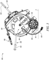
FIG. 1 shows a perspective view of a hose trolley in a driving position, in accordance with an aspect of the present invention; -
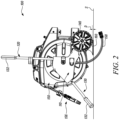
FIG. 2 shows a perspective side view of the hose trolley in an operating position, in accordance with an aspect of the present invention; -
FIG. 3 shows a perspective side view of the hose trolley in the driving position, in accordance with an aspect of the present invention; -
FIG. 4 shows a perspective view of the hose trolley in the operating position, in accordance with an aspect of the present invention; -
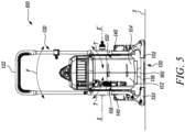
FIG. 5 shows a perspective front view of the hose trolley in the operating position, in accordance with an aspect of the present invention; and -
FIG. 6 shows a perspective back view of the hose trolley in the operating position, in accordance with an aspect of the present invention. - The present invention will be described more fully hereinafter with reference to the accompanying drawings, in which example embodiments of the invention incorporating one or more aspects of the present invention are shown. This invention may, however, be embodied in many different forms and should not be construed as limited to the embodiments set forth herein; rather, these embodiments are provided so that this disclosure will be thorough and complete, and will fully convey the scope of the invention to those skilled in the art. The invention is defined by the claims only.
- In the drawings, like numbers refer to like elements.
-
FIGS. 1 and2 illustrate ahose trolley 100. Thehose trolley 100 is used to house, store and transport a hose reel 150 (alternately referred to as a hose box 150) to different installations, such as lawns, parks, and the like for providing a flow of fluid, such as water. The present disclosure illustrates a hose box in various embodiments, however actual implantation may have any hose reel or box without any limitations. The flow of fluid may be provided for firefighting, gardening, surface cleaning and the like activities. Thehose trolley 100 includes aframe 110 that defines a central axis X-X'. Theframe 110 may be rigid as well as light weight, depending upon application requirements, user-preference, or other considerations. Theframe 110 may be manufactured using a metal (preferably aluminum), alloy and the like. Theframe 110 of thehose trolley 100 includes ahandle 120, asupport stand 130, one ormore wheels 140 and thehose box 150. Thehose box 150 is housed within theframe 110 along the central axis X-X'. Thehose box 150 may be connected to an external water source via ahose 158. Thehose box 150 may have a circular, a rectangular or any other shape without limiting the scope of the disclosure. Thehose box 150 may be made from metal, fiberglass, or plastic. Thehose box 150 includes afirst part 152 and asecond part 154. Thefirst part 152 and thesecond part 154 may be temporarily or permanently attached to each other, such as by fasteners, screws, any suitable means as used or known in the art. - As shown in
FIG. 2 , thehose trolley 100 further includes aground support element 160. Theground support element 160 allows the rotation (illustrated with turning direction "T" inFIG. 4 ) of thehose trolley 100 with respect to a level surface "S". Theground support element 160 along with the support stand 130 are adapted to support thehose box 150 on the level surface "S". Theground support element 160 may further be provided with support structures such as rubber inlay and the like to improve the stability of thehose trolley 100 under load if thehose 156 is pulled out an angle to thehose trolley 100. This may substantially reduce or eliminate the tendency of thehose trolley 100 to topple or fall-over (illustrated with fall direction "F" inFIG. 4 ) on the level surface "S" due to torque generated, say on hose pulling at an angle to thehose trolley 100. - The
hose trolley 100 has at least an operating position (as shown inFIG. 2 ) and a driving position (as shown inFIG. 3 ) operatively possible with the rotatable feature of theground support element 160. Theground support element 160 is rotatably connected to thehose trolley 100. Theground support element 160 is in a first position "P1" (as shown inFIG. 4 ) and a second position "P2" (as shown inFIG. 3 ) for the operating position and the driving position respectively of thehose trolley 100. In the first position "P1", theground support element 160 is engageable with the level surface "S", and in the second position "P2", theground support element 160 is disposed away from the level surface "S". Thus, theground support element 160 may operatively be rotated between the first position "P1" and the second position "P2" to allow for the dynamic stability in the operating position and the freedom of rotation (for driving, movement) of thewheels 140 in the driving position, respectively. - In some embodiments, in the first position "P1", the
ground support element 160 is substantially perpendicular to the central axis X-X', and in the second position "P2", theground support element 160 is at an angle relative to the central axis X-X'. - In the operating position, the
hose trolley 100 is supported on the level surface "S" by thesupport stand 130 and theground support element 160. The one ormore wheels 140 are at a distance "D" of about 1-2 cm, or any other distance as per the application or size of thewheels 140 or theground support element 160, from the level surface "S" in some embodiments. The one ormore wheels 140 do not contact the level surface "S" in the operating position. Thus, thehose trolley 100 may be able to freely turn (say about theground support element 160 along the turning direction "T") on experiencing torque and avoid or minimize the probability of toppling or fall-over (say the fall direction "F") on the level surface "S". - In the driving position, the
hose trolley 100 is supported on the level surface "S" by thewheels 140 and is movable on the level surface "S". Theground support element 160 is at a distance "d" of about 3-5 cm or any other distance as per the application or size of thewheels 140 or theground support element 160, from the level surface "S". Theground support element 160 and the support stand 130 do not contact the level surface "S". Thus, thehose trolley 100 may be easily maneuvered on the level surface "S", by engagement with thehandle 120, in the driving position with the help of the one ormore wheels 140. - As illustrated in
FIG. 4 , the support stand 130 may have aU-shape grip 136. The support stand 130 may preferably be formed in one piece or alternatively may be formed in two pieces connected to each other by any means know in the art. Thesupport stand 130 includes one ormore bases 132 which contact the level surface "S". Thebases 132 may be made of any material such as polymer, metal and the like, the present disclosure may be preferably implemented withplastic bases 132, and both these terms used interchangeably hereinafter. Theplastic bases 132 reduce the required bending radius of thesupport stand 130, which may be an aluminum tube. Further, the friction of theplastic bases 132 may be lower than the aluminum tube and thus additionally allows a better turning (say along the turning direction "T" substantially parallel to the level surface "S" as illustrated here) of thehose trolley 100, along with implementation benefits such as improved service life and the like. As illustrated inFIG. 4 , the one or moreplastic bases 132 are provided with one ormore rollers 134. The one ormore rollers 134 may be partially or fully in contact with the level surface "S". The present disclosure illustrates half portions of therollers 134 with thebases 132, however actual implementation of the present disclosure may have any arrangement, type, orientation, shape, size and the like of therollers 134. Therollers 134 on thebases 132 may further reduce friction for contact with the level surface "S". Thus, thehose trolley 100 may be able to turn with ease and eliminate or minimize the fall-over tendency on the level surface "S". - The
wheels 140, as shown inFIGS. 5 and6 , are two wheels which do not contact the level surface "S", when thehose trolley 100 is in the operating position. The twowheels 140 do not contact the level surface "S" so as to not to restrict the sideways or turning movement of thehose trolley 100. The twowheels 140 may be operationally coupled each on both the sides of thehose trolley 100 to provide sideways fall-over support. Thewheels 140 may be rotatably coupled with an axle (not shown). Thewheels 140 may ease support and movement of thehose trolley 100 on the level surface "S" or improve portability between different locations/installations. In some embodiments, thewheels 140 may becaster wheels 140. Thecaster wheels 140 may help to easily manipulate thehose trolley 100 on the level surface "S". In some embodiments, the one ormore wheels 140 and the axle may be provided with dampers (not shown) to avoid shocks incurred due to movement on any uneven surfaces, among other considerations. In some embodiments, the one ormore wheels 140 may be powered by an electric motor (not shown), or any other powering means. - In some embodiments, the
wheels 140 may be removably coupled with theframe 110. Thewheels 140 may be removable to allow easy servicing, or even replacement. Further, the removable feature of thewheels 140 may make thehose trolley 100 more compact for packaging. - The
hose trolley 100 includes thehandle 120. Thehandle 120 includes agrip portion 122. The grasping of thegrip portion 122 of thehandle 120 may provide better hold and safe working, movability of thehose trolley 100 between locations. In some embodiments, thegrip portion 122 may be defined as an inverted U-shaped portion of thehandle 120. The material used for thegrip portion 122 may preferably be, but need not necessarily, PVC or nitrile rubber, or any other plastic or polymer to suit application needs. - In some embodiments, the
handle 120 of thehose trolley 100 may be pivotably coupled to theframe 110. The pivotable nature of thehandle 120 may improve the ergonomics of thehose trolley 100. The pivotable handle 120 may also make thehose trolley 100 more compact for packaging, storage, and travel. In some embodiments, thehandle 120 includes a locking mechanism (not shown) to lock thehandle 120 in the pivotable position. The locking mechanism may provide a safe and trouble-free operation by disallowing any accidental movement of thepivotable handle 120. The locking mechanism may be lever such as a ringshaped lever to allow easy locking/unlocking of thehandle 120. In some embodiments, thehandle 120 may be telescopic. The telescopic nature of thehandle 120 may further improve the ergonomics of thehose trolley 100. The user may adjust the height of thehandle 120 to a comfortable position and easily hold or maneuver thehose trolley 100 on the level surface "S". - Thus, the present disclosure provides the
hose trolley 100 with improved dynamic stability. The dynamic stability in operating position is achieved by virtue of theground support element 160 and thesupport stand 130. Theground support element 160 and the support stand 130 assist in slight turning (the turning direction "T") or sideways movement of thehose trolley 100 as required when ahose 156 is pulled out of thehose box 150 at an angle relative to thehose trolley 100. Thus, a fall-over or toppling tendency (say along the fall direction "T") of thehose trolley 100 is substantially reduced or eliminated. Further, the dynamic stability in operating driving position is achieved by virtue of the one ormore wheels 140. The one ormore wheels 140 surface may be designed to provide better grip on the level surface "S" or avoid slip on the level surface "S". - In the drawings and specification, there have been disclosed preferred embodiments and examples of the invention and, although specific terms are employed, they are used in a generic and descriptive sense only and not for the purpose of limitation of the scope of the invention being set forth in the following claims.
-
- 100
- Hose Trolley
- 110
- Frame
- 120
- Handle
- 122
- Grip Portion
- 130
- Support Stand
- 132
- Bases
- 134
- Rollers
- 136
- Grip
- 140
- Wheels
- 150
- Hose Reel/Box
- 152
- First Part
- 154
- Second Part
- 156
- Hose
- 158
- Hose
- 160
- Ground Support Element
- X-X'
- Central Axis
- D
- Distance
- d
- Distance
- S
- Level Surface
- T
- Turning direction of hose trolley
- F
- Fall direction of hose trolley
- P1
- First Position
- P2
- Second Position
Claims (10)
- A hose trolley (100) comprising:a frame (110) defining a central axis (X-X'), wherein the frame (110) includes:a handle (120);a support stand (130); andone or more wheels (140);a hose reel (150) housed with the frame (110) along the central axis (X-X'),wherein the support stand (130) allows to support the hose trolley (100) on a level surface (S); anda ground support element (160);the hose trolley (100) has at least an operating position and a driving position, and wherein the ground support element (160) is rotatably connected to the hose trolley (100),wherein in the driving position, the hose trolley (100) is supported on the level surface (S) by the wheels (140), whereby the hose trolley (100) is movable on the level surface (S) in the driving position;characterized in that:
in the operating position, the hose trolley (100) is supported on the level surface (S) by the support stand (130) and the ground support element (160) such that the ground support element (160) allows the rotation of the hose trolley (100) with respect to the level surface (S) in a turning direction (T) substantially parallel to the level surface (S). - The hose trolley (100) of claim 1, wherein the ground support element (160) is in a first position (P1) and a second position (P2) for the operating position and the driving position respectively of the hose trolley (100).
- The hose trolley (100) of claim 2, wherein in the first position (P1) the ground support element (160) is engageable with the level surface (S) and in the second position (P2) the ground support element (160) is disposed away from the level surface (S).
- The hose trolley (100) of any of the preceding claims, wherein the wheels (140) are two wheels which do not contact the level surface (S), when the hose trolley (100) is in the operating position.
- The hose trolley (100) of any of the preceding claims, wherein the one or more wheels (140) are at a distance (D) of about 1-2 cm from the level surface (S).
- The hose trolley (100) of any of the preceding claims, wherein the support stand (130) includes one or more bases (132) which contact the level surface (S).
- The hose trolley (100) of claim 6, wherein the one or more bases (132) are provided with rollers (134).
- The hose trolley (100) of any of the preceding claims, wherein in the driving position the ground support element (160) is at a distance (d) of about 3-5 cm from the level surface (S).
- The hose trolley (100) of any of the preceding claims, wherein the handle (120) is pivotably coupled to the frame (110).
- The hose trolley (100) of any of the preceding claims, wherein the handle (120) is telescopic.
Priority Applications (4)
| Application Number | Priority Date | Filing Date | Title |
|---|---|---|---|
| FIEP21187320.3T FI4122799T3 (en) | 2021-07-23 | 2021-07-23 | Hose trolley |
| EP21187320.3A EP4122799B1 (en) | 2021-07-23 | 2021-07-23 | Hose trolley |
| CN202210841062.XA CN115676530A (en) | 2021-07-23 | 2022-07-18 | Hose cart |
| TW111127492A TW202319326A (en) | 2021-07-23 | 2022-07-22 | Hose trolley |
Applications Claiming Priority (1)
| Application Number | Priority Date | Filing Date | Title |
|---|---|---|---|
| EP21187320.3A EP4122799B1 (en) | 2021-07-23 | 2021-07-23 | Hose trolley |
Publications (2)
| Publication Number | Publication Date |
|---|---|
| EP4122799A1 EP4122799A1 (en) | 2023-01-25 |
| EP4122799B1 true EP4122799B1 (en) | 2024-02-21 |
Family
ID=77042771
Family Applications (1)
| Application Number | Title | Priority Date | Filing Date |
|---|---|---|---|
| EP21187320.3A Active EP4122799B1 (en) | 2021-07-23 | 2021-07-23 | Hose trolley |
Country Status (4)
| Country | Link |
|---|---|
| EP (1) | EP4122799B1 (en) |
| CN (1) | CN115676530A (en) |
| FI (1) | FI4122799T3 (en) |
| TW (1) | TW202319326A (en) |
Family Cites Families (6)
| Publication number | Priority date | Publication date | Assignee | Title |
|---|---|---|---|---|
| US5007598A (en) | 1989-10-25 | 1991-04-16 | O. Ames Co. | Hose reel assembly |
| US5915723A (en) * | 1997-04-04 | 1999-06-29 | Austin; Gloria E. | Collapsible utility cart |
| US9126612B2 (en) * | 2013-08-22 | 2015-09-08 | Hsiu-Man Yu Chen | Cable reel trolley |
| WO2018075365A1 (en) * | 2016-10-17 | 2018-04-26 | Great Stuff, Inc. | Pivotable reel assembly |
| CA3038159C (en) * | 2016-10-27 | 2019-12-17 | Husqvarna Ab | Hose cart |
| CN210102020U (en) * | 2019-06-12 | 2020-02-21 | 江苏塞孚航空科技有限公司 | Airport air conditioner hose winding and unwinding vehicle |
-
2021
- 2021-07-23 EP EP21187320.3A patent/EP4122799B1/en active Active
- 2021-07-23 FI FIEP21187320.3T patent/FI4122799T3/en active
-
2022
- 2022-07-18 CN CN202210841062.XA patent/CN115676530A/en active Pending
- 2022-07-22 TW TW111127492A patent/TW202319326A/en unknown
Also Published As
| Publication number | Publication date |
|---|---|
| FI4122799T3 (en) | 2024-03-14 |
| TW202319326A (en) | 2023-05-16 |
| EP4122799A1 (en) | 2023-01-25 |
| CN115676530A (en) | 2023-02-03 |
Similar Documents
| Publication | Publication Date | Title |
|---|---|---|
| CA2505175C (en) | Hose reel cart with tray constructed from plastic and metal structural components | |
| US4137939A (en) | Hose reel cart | |
| US5462298A (en) | Water hose cart | |
| US7871088B2 (en) | Cargo cart for wheeled mobility device | |
| CA2465674C (en) | Motorized cart with hub gear motor system | |
| US4974627A (en) | Garden hose reel caddy | |
| CA2596111A1 (en) | Swivel metal hose cart | |
| US20080098544A1 (en) | Drain cleaning machine with added stability, portability and maneuverability | |
| US20090152826A1 (en) | Cargo cart with hitch for wheeled mobility device | |
| TWI728185B (en) | Hose cart | |
| EP4122799B1 (en) | Hose trolley | |
| US20040231917A1 (en) | Scaffold moving device | |
| RU2086448C1 (en) | Swivel wheel control device | |
| US20060055133A1 (en) | Guide wheel assembly for carts | |
| CN117715850A (en) | Movable hose reel assembly | |
| EP4245709B1 (en) | Hose trolley | |
| CA2638613A1 (en) | Cargo cart for wheeled mobility device | |
| CA1229834A (en) | Hose storage apparatus | |
| CA2825750C (en) | Wall mountable hose reel | |
| CN117429491A (en) | Tiger climbs stair forklift |
Legal Events
| Date | Code | Title | Description |
|---|---|---|---|
| PUAI | Public reference made under article 153(3) epc to a published international application that has entered the european phase |
Free format text: ORIGINAL CODE: 0009012 |
|
| STAA | Information on the status of an ep patent application or granted ep patent |
Free format text: STATUS: REQUEST FOR EXAMINATION WAS MADE |
|
| 17P | Request for examination filed |
Effective date: 20221108 |
|
| AK | Designated contracting states |
Kind code of ref document: A1 Designated state(s): AL AT BE BG CH CY CZ DE DK EE ES FI FR GB GR HR HU IE IS IT LI LT LU LV MC MK MT NL NO PL PT RO RS SE SI SK SM TR |
|
| GRAP | Despatch of communication of intention to grant a patent |
Free format text: ORIGINAL CODE: EPIDOSNIGR1 |
|
| STAA | Information on the status of an ep patent application or granted ep patent |
Free format text: STATUS: GRANT OF PATENT IS INTENDED |
|
| INTG | Intention to grant announced |
Effective date: 20231128 |
|
| GRAS | Grant fee paid |
Free format text: ORIGINAL CODE: EPIDOSNIGR3 |
|
| GRAA | (expected) grant |
Free format text: ORIGINAL CODE: 0009210 |
|
| STAA | Information on the status of an ep patent application or granted ep patent |
Free format text: STATUS: THE PATENT HAS BEEN GRANTED |
|
| P01 | Opt-out of the competence of the unified patent court (upc) registered |
Effective date: 20231219 |
|
| AK | Designated contracting states |
Kind code of ref document: B1 Designated state(s): AL AT BE BG CH CY CZ DE DK EE ES FI FR GB GR HR HU IE IS IT LI LT LU LV MC MK MT NL NO PL PT RO RS SE SI SK SM TR |
|
| REG | Reference to a national code |
Ref country code: GB Ref legal event code: FG4D |
|
| REG | Reference to a national code |
Ref country code: CH Ref legal event code: EP |
|
| REG | Reference to a national code |
Ref country code: DE Ref legal event code: R096 Ref document number: 602021009543 Country of ref document: DE |
|
| REG | Reference to a national code |
Ref country code: IE Ref legal event code: FG4D |