EP4122773B1 - Software update device, software update method, and software update processing program - Google Patents
Software update device, software update method, and software update processing program Download PDFInfo
- Publication number
- EP4122773B1 EP4122773B1 EP20925585.0A EP20925585A EP4122773B1 EP 4122773 B1 EP4122773 B1 EP 4122773B1 EP 20925585 A EP20925585 A EP 20925585A EP 4122773 B1 EP4122773 B1 EP 4122773B1
- Authority
- EP
- European Patent Office
- Prior art keywords
- software
- equipment
- warning
- update process
- updating
- Prior art date
- Legal status (The legal status is an assumption and is not a legal conclusion. Google has not performed a legal analysis and makes no representation as to the accuracy of the status listed.)
- Active
Links
Images

Classifications
-
- G—PHYSICS
- G06—COMPUTING OR CALCULATING; COUNTING
- G06F—ELECTRIC DIGITAL DATA PROCESSING
- G06F8/00—Arrangements for software engineering
- G06F8/60—Software deployment
- G06F8/65—Updates
-
- B—PERFORMING OPERATIONS; TRANSPORTING
- B60—VEHICLES IN GENERAL
- B60R—VEHICLES, VEHICLE FITTINGS, OR VEHICLE PARTS, NOT OTHERWISE PROVIDED FOR
- B60R16/00—Electric or fluid circuits specially adapted for vehicles and not otherwise provided for; Arrangement of elements of electric or fluid circuits specially adapted for vehicles and not otherwise provided for
- B60R16/02—Electric or fluid circuits specially adapted for vehicles and not otherwise provided for; Arrangement of elements of electric or fluid circuits specially adapted for vehicles and not otherwise provided for electric constitutive elements
Definitions
- the present invention relates to a software updating device, a software update method, and a software updating process program.
- JP 2018-97764 A discloses an onboard data updating device in which an onboard control unit receives update data from an external server and updates (performs an update process on) a unit that is to be updated by using the aforementioned update data.
- JP 2020-027629 A describes a master device for a vehicle includes: an install condition determination unit for determining whether a first condition, in which there is an approval of install by a user, a second condition, in which the master device is ready to communicate with a center device, a third condition, in which the state of a vehicle is ready to be installed, and a fourth condition, in which a rewriting target ECU is ready to be installed, and a fifth condition, in which update data is normal data, are all established; and an install instruction unit for instructing the rewriting target ECU to install using the update data if the install condition determination unit has determined that the first, second, third, fourth, and fifth conditions are all established.
- the present invention was contrived in view of the above-mentioned problems, it being an object of the present invention to provide a software updating device, a software update method, and a software updating process program in which outputting of unnecessary warnings arising from a software update process is prevented.
- the present invention provides a software updating device, a method for updating software that operates a vehicle-mounted equipment, and a software updating process program for implementing a process for updating software that operates a vehicle-mounted equipment as defined in the appended independent claims. Further advantageous effects can be achieved by preferred embodiments defined in the appended dependent claims.
- the present invention provides software updating device that executes a process for updating software that operates a vehicle-mounted equipment, the software updating device comprising a controller that acquires the software and applies the software to the equipment to control the equipment, and the controller being configured to acquire the software and apply the software to the equipment, thereby executing the update process; cause a warning device to output a warning when an abnormality relating to the equipment is detected while the update process is not being executed; and record a fault code corresponding to the abnormality in a storage region of the controller and cause the warning device to output the warning based on the fault code that was recorded when the abnormality relating to the equipment occurs; prohibit outputting of the warning by the warning device when the abnormality relating to the equipment is detected while the update process is being executed; and prohibit the outputting of the warning by the warning device without recording the fault code when the abnormality relating to the equipment occurs while the update process is being executed.
- Figure 1 is a schematic block diagram of a software update system 100 and a software updating device 110 according to this embodiment of the present invention.
- the software update system 100 is configured from a software updating device 110 mounted in a vehicle 1, and an external server 2.
- the software updating device 110 is configured from a controller 10 and a warning device 3.
- the vehicle 1 is, e.g., an electric vehicle (EV).
- EV electric vehicle
- the controller 10 includes a gateway 11 that acquires software from the external server 2, and electronic control units 12 that control various pieces of equipment mounted in the vehicle 1.
- the gateway 11 is capable of communicating with the external server 2 and the electronic control units 12.
- the gateway 11 acquires updating software from the external server 2 and transmits the aforementioned acquired updating software to electronic control units 12 that are to be updated. Additionally, the gateway 11 is also capable of communicating with the warning device 3, which shall be described later.
- the gateway 11 acquires control information for the various pieces of equipment from the electronic control units 12 and senses the occurrence of an abnormality relating to the various pieces of equipment from the aforementioned control information.
- the gateway 11 has a storage region for recording a fault code when an abnormality occurs. Upon sensing the occurrence of an abnormality in the various pieces of equipment, the gateway 11 records a fault code corresponding to the aforementioned abnormality in the storage region. When the fault code is recorded in the storage region, the gateway 11 outputs a warning by using the warning device 3 on the basis of the recorded fault code.
- the gateway 11 is configured from a computer provided with a central processing device (CPU), a read-only memory (ROM), a random access memory (RAM), and an input/output interface (I/O interface), the gateway 11 integrally controlling the software updating device 110. By executing a specific program, the gateway 11 executes a process for controlling the software updating device 110. Together with, e.g., the electronic control units 12, the gateway 11 performs software update control that shall be described later.
- CPU central processing device
- ROM read-only memory
- RAM random access memory
- I/O interface input/output interface
- the electronic control units (ECUs) 12 are controllers that control the various pieces of equipment mounted in the vehicle 1, and include, e.g., a body control module (BCM), a vehicle dynamics control (VDC), and a hybrid electric vehicle control (HEVC).
- the various ECUs 12 are each configured from a computer provided with a central processing device (CPU), a read-only memory (ROM), a random access memory (RAM), and an input/output interface (I/O interface).
- the BCM controls operating elements in a body of the vehicle 1, including an engine starter, a door lock, etc., of the vehicle 1.
- the VDC controls output of brakes or an engine of the vehicle 1 and controls an orientation of the vehicle 1, thereby preventing, inter alia, lateral sliding of the vehicle 1.
- the HEVC controls the engine and a motor, which are drive sources, and realizes high-efficiency driving.
- the ECUs 12 are capable of communicating with the gateway 11 and continuously transmit control information for the various pieces of equipment to the gateway 11 in the form of signals.
- the various ECUs 12 acquire software including the specific program from the gateway 11 and apply the acquired software to the equipment being controlled, thereby controlling the equipment.
- the ECUs 12 also perform, together with the gateway 11, the software update control that shall be described later.
- the various ECUs 12 are also each provided with two storage units 121, 122 that store the software acquired from the gateway 11.
- the ECUs 12 apply the software stored in one storage unit (first storage unit) 121 to the equipment, and change the software being applied to the equipment to the software stored in the other storage unit (second storage unit) 122, thereby updating the software. Further details about a software update process shall be described later.
- the warning device 3 is, e.g., a warning lamp in the vehicle 1.
- the warning device 3 informs the driver, etc., about the aforementioned abnormality.
- the warning device 3 is capable of communicating with the gateway 11.
- the gateway 11 Upon sensing the occurrence of an abnormality in onboard equipment, the gateway 11 records a fault code corresponding to the aforementioned abnormality in the storage region and, for example, causes the warning lamp, which is the warning device 3, to illuminate, thereby outputting a warning.
- the warning device 3 is not limited to being a warning lamp, and can be, e.g., an alarm that operates through sound.
- the various ECUs 12 are each provided with two storage units 121, 122.
- the ECUs 12 acquire software (first software) that is transmitted from the gateway 11, the aforementioned software is stored in one storage unit (first storage unit) 121, and the ECUs 12 apply the aforementioned software to the equipment.
- the first software can also be already stored in the first storage unit 121 in an initial state rather than being acquired from the gateway 11.
- the ECUs 12 When the ECUs 12 then acquire updating software (second software) that is transmitted from the gateway 11, the aforementioned updating software is stored in the other storage unit (second storage unit) 122. The first software is still applied to the equipment while the ECUs 12 are acquiring and storing the second software.
- providing two storage units 121, 122 to each of the various ECUs 12 makes it possible for the ECUs 12 to acquire (download) and store (install) the updating software in a state in which the first software is applied to the equipment. Specifically, it is possible to acquire and store the updating software without stopping operation of the equipment being controlled.
- the ECUs 12 Upon acquiring and storing the updating software (second software), the ECUs 12 change the software applied to the equipment from the first software to the second software. The software applied to the equipment is thereby updated.
- the process for changing the software applied to the equipment from the first software to the second software is referred to below as a software update process (activation).
- the gateway 11 does not record a fault code in the storage region even if the occurrence of an abnormality relating to the equipment is sensed. This makes it possible for outputting of warnings while the software update process is being executed to be prohibited.
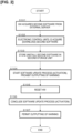
- FIG. 2 is a flowchart illustrating software update control according to the one embodiment of the present invention.
- the control described below is, in either instance, executed by the controller 10 (gateway 11 and ECUs 12).
- the first software is stored in the first storage units 121 of the ECUs 12 in an initial state, and is applied to the equipment being controlled.
- step S101 upon acquiring the updating software (second software) from the external server 2, the gateway (GW) 11 transmits the aforementioned updating software to the ECUs 12 that are to be updated.
- step S102 the ECUs 12 acquire (download) the updating software (second software) from the gateway 11.
- step S103 the ECUs 12 store (install) the updating software (second software) in the second storage unit 122. Because the first software is still applied to the equipment being controlled by the ECUs 12 while the second software is being acquired and stored in steps S102 and S103, the equipment being controlled by the ECUs 12 is not stopped. Therefore, for example, the updating software can be acquired and stored even while the vehicle 1 is traveling. Additionally, because the updating software can be activated within a short time, it is possible to perform processes for acquiring, storing, and updating the software in a state in which an ignition switch is turned on (including while the vehicle 1 is traveling).
- step S104 the gateway 11 prohibits outputting of warnings by the warning device 3 simultaneously with starting of the software update process by the ECUs 12.
- the ECUs 12 change the software applied to the equipment being controlled from the first software to the second software, whereby the software update process is executed.
- the software applied to the equipment is thereby updated from the first software to the second software.
- the driver it is preferable for the driver to be notified via a display device, etc. (not shown), that the update process is in progress.
- Outputting of warnings is prohibited by, e.g., masking the storage region of the gateway 11. As a consequence, fault codes are not recorded in the storage region even if the gateway 11 senses the occurrence of an abnormality relating to the equipment. Therefore, outputting of warnings by the warning device 3 is prohibited.
- Step S104 can be configured such that the update process is permitted only when no occurrence of abnormality is sensed before the software update process is started.
- the gateway 11 senses whether an abnormality has occurred in the equipment controlled by the pre-software-update ECUs 12 and transmits results of the aforementioned sensing to the ECUs 12.
- the ECUs 12 execute the update process only when no occurrence of abnormality has been sensed.
- the ECUs 12 prohibit the software update process until the aforementioned abnormality is eliminated.
- outputting of warnings while the software update process is being executed is prohibited, no warning is outputted even with respect to an abnormality not arising from the update process. Therefore, eliminating an abnormality not arising from the software update process before starting the software update process reliably prevents a countermeasure to the abnormality from being delayed until after the software update process.
- the software update process can be permitted or prohibited by the gateway 11.
- the gateway 11 in step S105, temporarily resets the hardware (HW) of the ECUs 12 that are to be updated and updates the software rewrite details. Once the HW of the ECUs 12 is reset, communications between the ECUs 12 that are to be updated and the ECUs 12 that control other onboard equipment are temporarily cut.
- the gateway 11 senses the severance of communication as the occurrence of an abnormality relating to the equipment, but because the storage region of the gateway 11 is masked, no fault code is recorded in the storage region. Therefore, no warning is outputted.
- step S106 the gateway 11, in step S107, removes the prohibition on outputting of warnings (permits outputting of warnings) and terminates the software update process.
- a warning will be outputted after the prohibition on outputting of warnings is removed, provided that the aforementioned abnormality is not eliminated even after the software update process has concluded.
- the prohibition on outputting of warnings is preferably removed immediately after conclusion of the software update process, but such an arrangement is not necessarily provided by way of limitation. For example, outputting of warnings can be permitted after a fixed time has elapsed.
- updating software that is transmitted from the gateway 11 to the ECUs 12 is stored (written over) in the first storage unit 121.
- the software applied to the equipment is changed from the second software stored in the second storage unit 122 to the aforementioned updating software that is stored in the first storage unit 121, whereby the software is re-updated.
- Fig. 2 The processes shown in Fig. 2 are configured as programs that are to be executed by the controller 10, which is a computer. These programs are written in a storage medium.
- the gateway 11 causes the warning device 3 to output a warning when an abnormality relating to the equipment occurs, and prohibits outputting of warnings by the warning device 3 while the software update process is being executed. Because outputting of warnings while the software update process is being executed is prohibited, no warning is outputted even if the HW of the ECUs 12 is temporarily reset and communication with other electronic control units is temporarily severed in order to update the software rewrite details. Therefore, it is possible to prevent outputting of unnecessary warnings arising from the software update process.
- the gateway 11 (controller 10) prohibits outputting of warnings while the software update process is being executed, and permits outputting of warnings after the software update process has concluded. This makes it possible to prevent outputting of unnecessary warnings arising from the software update process and to warn the driver, etc., about an equipment abnormality not arising from the software update process, the warning being issued after the software update process.
- the gateway 11 In the software updating device 110, when an abnormality relating to the equipment occurs, the gateway 11 (controller 10) records a fault code corresponding to the aforementioned abnormality in a storage region of the gateway 11 (controller 10), and causes the warning device 3 to output a warning on the basis of the recorded fault code.
- the gateway 11 does not record a fault code while the software update process is being executed even if an abnormality relating to the equipment occurs. Therefore, no warning is outputted by the warning device 3 while the software update process is being executed. It is therefore possible to prevent outputting of unnecessary warnings arising from the software update process.
- each of the ECUs 12 (controller 10) has the first storage unit 121 that stores the first software and the second storage unit 122 that stores the second software. Therefore, it is possible to acquire the updating software (second software) and to store the updating software in the second storage unit 122 in a state in which the first software stored in the first storage unit 121 is applied to the equipment. It is therefore possible to acquire and store the updating software without stopping the equipment controlled by the ECUs 12 that are to be updated, and convenience during software update work is improved.
- the software updating device 110 is provided with a plurality of ECUs 12 that control each of a plurality of equipment, and each of the plurality of ECUs 12 executes the software update process.
- the gateway 11 (controller 10) prohibits outputting of warnings by the warning device 3 while the software update processes are being executed.
- prohibiting outputting of warnings while the software update processes of the various ECUs 12 are being executed makes it possible to prevent a plurality of warnings arising from the software update processes of the various ECUs 12 from being issued one after another and causing more undue concern on the part of the driver, etc.
- a BCM, a VDC, and an HEVC are employed as the ECUs 12, but the types of ECUs 12 and the quantity thereof are not limited to those in the present embodiment, provided that the ECUs 12 control equipment mounted in the vehicle 1.
- the software update control including the software update process according to the present embodiment can be executed simultaneously in any number of the plurality of ECUs 12, or can be executed at different times for each of the various ECUs 12.
- the gateway 11 integrally controls the software updating device 110 and the ECUs 12 control the various pieces of equipment mounted in the vehicle 1.
- the elements executing the various controls can be either of the gateway 11 and the ECUs 12.
- the changing of the software applied to the equipment i.e., the software update process
- the gateway 11 can be executed by the gateway 11 rather than by the ECUs 12.
- a fault code corresponding to the aforementioned abnormality is recorded in the storage region of the gateway 11, and a warning is outputted by the warning device 3 on the basis of the recorded fault code.
- the method for outputting a warning is not limited to this arrangement.
- the warning device 3 can be directly caused to output a warning, without a fault code having been recorded.
- the storage region of the gateway 11 is masked and no fault code is recorded while the software update process is being executed, whereby outputting of warnings while the update process is being executed is prohibited.
- the method for prohibiting warnings is not necessarily limited to this arrangement. For example, when the occurrence of an abnormality in the equipment is sensed as described above, in a case in which the warning device 3 is directly caused to output a warning without a fault code having been recorded, the prohibition on outputting of warnings also involves directly prohibiting the warning device 3 from outputting warnings.
- the ECUs 12 are each configured so as to have two storage units 121, 122.
- each of the ECUs 12 it is preferable for each of the ECUs 12 to have two storage units 121, 122 in order to make it possible to acquire and store the updating software without stopping the onboard equipment, but the ECUs 12 can also each be configured so as to have only one storage unit.
- the updating software is written over the software stored in the aforementioned storage unit, whereby the software update process is performed. Outputting of warnings is also prohibited while the updating software is being acquired and stored when each of the ECUs 12 has only one storage unit.
Landscapes
- Engineering & Computer Science (AREA)
- Software Systems (AREA)
- General Engineering & Computer Science (AREA)
- Theoretical Computer Science (AREA)
- Computer Security & Cryptography (AREA)
- Physics & Mathematics (AREA)
- General Physics & Mathematics (AREA)
- Mechanical Engineering (AREA)
- Stored Programmes (AREA)
Description
- The present invention relates to a software updating device, a software update method, and a software updating process program.
-
JP 2018-97764 A -
JP 2020-027629 A - However, when a process for updating software in a vehicle-mounted electronic control unit (ECU) is to be performed, hardware of the ECU is temporarily reset in order to update software rewrite details. Because communications with other onboard equipment are temporarily cut during the reset, an abnormality is assessed to have occurred, a fault code is recorded in a control unit of the vehicle, and a warning is issued to the driver, etc. Therefore, the driver, etc., might be misled into thinking that the software update process has failed or that a fault has occurred in the vehicle, which might cause undue concern on the part of the driver, etc.
- The present invention was contrived in view of the above-mentioned problems, it being an object of the present invention to provide a software updating device, a software update method, and a software updating process program in which outputting of unnecessary warnings arising from a software update process is prevented.
- The present invention provides a software updating device, a method for updating software that operates a vehicle-mounted equipment, and a software updating process program for implementing a process for updating software that operates a vehicle-mounted equipment as defined in the appended independent claims. Further advantageous effects can be achieved by preferred embodiments defined in the appended dependent claims.
- Namely, the present invention provides software updating device that executes a process for updating software that operates a vehicle-mounted equipment, the software updating device comprising a controller that acquires the software and applies the software to the equipment to control the equipment, and the controller being configured to acquire the software and apply the software to the equipment, thereby executing the update process; cause a warning device to output a warning when an abnormality relating to the equipment is detected while the update process is not being executed; and record a fault code corresponding to the abnormality in a storage region of the controller and cause the warning device to output the warning based on the fault code that was recorded when the abnormality relating to the equipment occurs; prohibit outputting of the warning by the warning device when the abnormality relating to the equipment is detected while the update process is being executed; and prohibit the outputting of the warning by the warning device without recording the fault code when the abnormality relating to the equipment occurs while the update process is being executed.
-
-
Figure 1 is a schematic block diagram of a software update system according to one embodiment of the present invention. -
Figure 2 is a flowchart illustrating software update control according to the one embodiment of the present invention. - An embodiment of the present invention is described below with reference to the accompanying drawings, etc.
- One embodiment of the present invention is described with reference to
Figs. 1 and2 .Figure 1 is a schematic block diagram of asoftware update system 100 and asoftware updating device 110 according to this embodiment of the present invention. - As shown in
Fig. 1 , thesoftware update system 100 is configured from asoftware updating device 110 mounted in a vehicle 1, and an external server 2. Thesoftware updating device 110 is configured from acontroller 10 and awarning device 3. The vehicle 1 is, e.g., an electric vehicle (EV). - The
controller 10 includes agateway 11 that acquires software from the external server 2, andelectronic control units 12 that control various pieces of equipment mounted in the vehicle 1. - The
gateway 11 is capable of communicating with the external server 2 and theelectronic control units 12. Thegateway 11 acquires updating software from the external server 2 and transmits the aforementioned acquired updating software toelectronic control units 12 that are to be updated. Additionally, thegateway 11 is also capable of communicating with thewarning device 3, which shall be described later. Thegateway 11 acquires control information for the various pieces of equipment from theelectronic control units 12 and senses the occurrence of an abnormality relating to the various pieces of equipment from the aforementioned control information. Thegateway 11 has a storage region for recording a fault code when an abnormality occurs. Upon sensing the occurrence of an abnormality in the various pieces of equipment, thegateway 11 records a fault code corresponding to the aforementioned abnormality in the storage region. When the fault code is recorded in the storage region, thegateway 11 outputs a warning by using thewarning device 3 on the basis of the recorded fault code. - The
gateway 11 is configured from a computer provided with a central processing device (CPU), a read-only memory (ROM), a random access memory (RAM), and an input/output interface (I/O interface), thegateway 11 integrally controlling thesoftware updating device 110. By executing a specific program, thegateway 11 executes a process for controlling the software updatingdevice 110. Together with, e.g., theelectronic control units 12, thegateway 11 performs software update control that shall be described later. - The electronic control units (ECUs) 12 are controllers that control the various pieces of equipment mounted in the vehicle 1, and include, e.g., a body control module (BCM), a vehicle dynamics control (VDC), and a hybrid electric vehicle control (HEVC). The
various ECUs 12 are each configured from a computer provided with a central processing device (CPU), a read-only memory (ROM), a random access memory (RAM), and an input/output interface (I/O interface). The BCM controls operating elements in a body of the vehicle 1, including an engine starter, a door lock, etc., of the vehicle 1. The VDC controls output of brakes or an engine of the vehicle 1 and controls an orientation of the vehicle 1, thereby preventing, inter alia, lateral sliding of the vehicle 1. When the vehicle 1 is a hybrid vehicle, the HEVC controls the engine and a motor, which are drive sources, and realizes high-efficiency driving. - The
ECUs 12 are capable of communicating with thegateway 11 and continuously transmit control information for the various pieces of equipment to thegateway 11 in the form of signals. Thevarious ECUs 12 acquire software including the specific program from thegateway 11 and apply the acquired software to the equipment being controlled, thereby controlling the equipment. TheECUs 12 also perform, together with thegateway 11, the software update control that shall be described later. - The
various ECUs 12 are also each provided with twostorage units gateway 11. TheECUs 12 apply the software stored in one storage unit (first storage unit) 121 to the equipment, and change the software being applied to the equipment to the software stored in the other storage unit (second storage unit) 122, thereby updating the software. Further details about a software update process shall be described later. - The
warning device 3 is, e.g., a warning lamp in the vehicle 1. When an abnormality occurs in the various pieces of equipment mounted in the vehicle 1, thewarning device 3 informs the driver, etc., about the aforementioned abnormality. Thewarning device 3 is capable of communicating with thegateway 11. Upon sensing the occurrence of an abnormality in onboard equipment, thegateway 11 records a fault code corresponding to the aforementioned abnormality in the storage region and, for example, causes the warning lamp, which is thewarning device 3, to illuminate, thereby outputting a warning. Thewarning device 3 is not limited to being a warning lamp, and can be, e.g., an alarm that operates through sound. - The software update process is described next.
- As described previously, the
various ECUs 12 are each provided with twostorage units ECUs 12 acquire software (first software) that is transmitted from thegateway 11, the aforementioned software is stored in one storage unit (first storage unit) 121, and theECUs 12 apply the aforementioned software to the equipment. The first software can also be already stored in thefirst storage unit 121 in an initial state rather than being acquired from thegateway 11. - When the
ECUs 12 then acquire updating software (second software) that is transmitted from thegateway 11, the aforementioned updating software is stored in the other storage unit (second storage unit) 122. The first software is still applied to the equipment while theECUs 12 are acquiring and storing the second software. - Thus, providing two
storage units various ECUs 12 makes it possible for theECUs 12 to acquire (download) and store (install) the updating software in a state in which the first software is applied to the equipment. Specifically, it is possible to acquire and store the updating software without stopping operation of the equipment being controlled. - Upon acquiring and storing the updating software (second software), the ECUs 12 change the software applied to the equipment from the first software to the second software. The software applied to the equipment is thereby updated. The process for changing the software applied to the equipment from the first software to the second software is referred to below as a software update process (activation).
- When the process for updating the software in the
ECUs 12 is to be performed, hardware in theECUs 12 is temporarily reset in order to update software rewrite details. Because communications between theECUs 12 that are to be updated andECUs 12 that control other onboard equipment are temporarily cut during the reset, an abnormality in the equipment is assessed to have occurred, and a fault code is recorded in the storage region of thegateway 11. A warning is therefore issued to the driver, etc., by thewarning device 3. Therefore, the driver, etc., might be misled into thinking that the software update process has failed or that a fault has occurred in the vehicle 1, which might cause undue concern on the part of the driver, etc. Additionally, because software update processes of thevarious ECUs 12 are not limited to being executed simultaneously, it is also possible that a plurality of warnings will be issued one after another. There is a risk that such issuance of a plurality of warnings might cause more undue concern on the part of the driver, etc. Thus, in the present embodiment, outputting of warnings by thewarning device 3 while the software update process is being executed is prohibited. - Specifically, while the software update process is being executed, the
gateway 11 does not record a fault code in the storage region even if the occurrence of an abnormality relating to the equipment is sensed. This makes it possible for outputting of warnings while the software update process is being executed to be prohibited. - Thus, because outputting of warnings by the
warning device 3 while the software update process is being executed is prohibited, it is possible to prevent outputting of unnecessary warnings arising from the software update process. - In a case in which the occurrence of an equipment abnormality not arising from the software update process is sensed after outputting of warnings is prohibited, a fault code will be recorded and a warning will be outputted after conclusion of the update process, provided that the aforementioned abnormality is not eliminated even after the software update process has concluded.
-
Figure 2 is a flowchart illustrating software update control according to the one embodiment of the present invention. The control described below is, in either instance, executed by the controller 10 (gateway 11 and ECUs 12). The first software is stored in thefirst storage units 121 of theECUs 12 in an initial state, and is applied to the equipment being controlled. - In step S101, upon acquiring the updating software (second software) from the external server 2, the gateway (GW) 11 transmits the aforementioned updating software to the
ECUs 12 that are to be updated. - In step S102, the
ECUs 12 acquire (download) the updating software (second software) from thegateway 11. - Next, in step S103, the
ECUs 12 store (install) the updating software (second software) in thesecond storage unit 122. Because the first software is still applied to the equipment being controlled by theECUs 12 while the second software is being acquired and stored in steps S102 and S103, the equipment being controlled by theECUs 12 is not stopped. Therefore, for example, the updating software can be acquired and stored even while the vehicle 1 is traveling. Additionally, because the updating software can be activated within a short time, it is possible to perform processes for acquiring, storing, and updating the software in a state in which an ignition switch is turned on (including while the vehicle 1 is traveling). - In step S104, the
gateway 11 prohibits outputting of warnings by thewarning device 3 simultaneously with starting of the software update process by theECUs 12. - The
ECUs 12 change the software applied to the equipment being controlled from the first software to the second software, whereby the software update process is executed. The software applied to the equipment is thereby updated from the first software to the second software. During the software update process, it is preferable for the driver to be notified via a display device, etc. (not shown), that the update process is in progress. - Outputting of warnings is prohibited by, e.g., masking the storage region of the
gateway 11. As a consequence, fault codes are not recorded in the storage region even if thegateway 11 senses the occurrence of an abnormality relating to the equipment. Therefore, outputting of warnings by thewarning device 3 is prohibited. - Step S104 can be configured such that the update process is permitted only when no occurrence of abnormality is sensed before the software update process is started. For example, the
gateway 11 senses whether an abnormality has occurred in the equipment controlled by the pre-software-update ECUs 12 and transmits results of the aforementioned sensing to theECUs 12. TheECUs 12 execute the update process only when no occurrence of abnormality has been sensed. In a case in which the occurrence of an abnormality in the equipment is sensed before the software update process is executed, theECUs 12 prohibit the software update process until the aforementioned abnormality is eliminated. Specifically, because outputting of warnings while the software update process is being executed is prohibited, no warning is outputted even with respect to an abnormality not arising from the update process. Therefore, eliminating an abnormality not arising from the software update process before starting the software update process reliably prevents a countermeasure to the abnormality from being delayed until after the software update process. The software update process can be permitted or prohibited by thegateway 11. - Once the software update process is started in step S104, the
gateway 11, in step S105, temporarily resets the hardware (HW) of theECUs 12 that are to be updated and updates the software rewrite details. Once the HW of theECUs 12 is reset, communications between theECUs 12 that are to be updated and theECUs 12 that control other onboard equipment are temporarily cut. Thegateway 11 senses the severance of communication as the occurrence of an abnormality relating to the equipment, but because the storage region of thegateway 11 is masked, no fault code is recorded in the storage region. Therefore, no warning is outputted. - Next, once the software update process has concluded in step S106, the
gateway 11, in step S107, removes the prohibition on outputting of warnings (permits outputting of warnings) and terminates the software update process. - Thus, because outputting of warnings by the
warning device 3 while the software update process is being executed is prohibited, it is possible to prevent outputting of unnecessary warnings arising from the software update process. - Additionally, in a case in which the occurrence of an equipment abnormality not arising from the software update process is sensed by the
gateway 11 over the course of steps S104 to S107 after outputting of warnings is prohibited, a warning will be outputted after the prohibition on outputting of warnings is removed, provided that the aforementioned abnormality is not eliminated even after the software update process has concluded. - The prohibition on outputting of warnings is preferably removed immediately after conclusion of the software update process, but such an arrangement is not necessarily provided by way of limitation. For example, outputting of warnings can be permitted after a fixed time has elapsed.
- After the software update process has concluded, when the software is furthermore updated in a subsequent instance, updating software that is transmitted from the
gateway 11 to theECUs 12 is stored (written over) in thefirst storage unit 121. The software applied to the equipment is changed from the second software stored in thesecond storage unit 122 to the aforementioned updating software that is stored in thefirst storage unit 121, whereby the software is re-updated. - The processes shown in
Fig. 2 are configured as programs that are to be executed by thecontroller 10, which is a computer. These programs are written in a storage medium. - By using the
software updating device 110 according to the embodiment described above, it is possible to obtain the following effects. - In the
software updating device 110, the gateway 11 (controller 10) causes thewarning device 3 to output a warning when an abnormality relating to the equipment occurs, and prohibits outputting of warnings by thewarning device 3 while the software update process is being executed. Because outputting of warnings while the software update process is being executed is prohibited, no warning is outputted even if the HW of theECUs 12 is temporarily reset and communication with other electronic control units is temporarily severed in order to update the software rewrite details. Therefore, it is possible to prevent outputting of unnecessary warnings arising from the software update process. - In the
software updating device 110, the gateway 11 (controller 10) prohibits outputting of warnings while the software update process is being executed, and permits outputting of warnings after the software update process has concluded. This makes it possible to prevent outputting of unnecessary warnings arising from the software update process and to warn the driver, etc., about an equipment abnormality not arising from the software update process, the warning being issued after the software update process. - In the
software updating device 110, when an abnormality relating to the equipment occurs, the gateway 11 (controller 10) records a fault code corresponding to the aforementioned abnormality in a storage region of the gateway 11 (controller 10), and causes thewarning device 3 to output a warning on the basis of the recorded fault code. However, the gateway 11 (controller 10) does not record a fault code while the software update process is being executed even if an abnormality relating to the equipment occurs. Therefore, no warning is outputted by thewarning device 3 while the software update process is being executed. It is therefore possible to prevent outputting of unnecessary warnings arising from the software update process. - In the
software updating device 110, each of the ECUs 12 (controller 10) has thefirst storage unit 121 that stores the first software and thesecond storage unit 122 that stores the second software. Therefore, it is possible to acquire the updating software (second software) and to store the updating software in thesecond storage unit 122 in a state in which the first software stored in thefirst storage unit 121 is applied to the equipment. It is therefore possible to acquire and store the updating software without stopping the equipment controlled by theECUs 12 that are to be updated, and convenience during software update work is improved. - The
software updating device 110 is provided with a plurality ofECUs 12 that control each of a plurality of equipment, and each of the plurality ofECUs 12 executes the software update process. The gateway 11 (controller 10) prohibits outputting of warnings by thewarning device 3 while the software update processes are being executed. Thus, prohibiting outputting of warnings while the software update processes of thevarious ECUs 12 are being executed makes it possible to prevent a plurality of warnings arising from the software update processes of thevarious ECUs 12 from being issued one after another and causing more undue concern on the part of the driver, etc. - In the present embodiment, a BCM, a VDC, and an HEVC are employed as the
ECUs 12, but the types ofECUs 12 and the quantity thereof are not limited to those in the present embodiment, provided that theECUs 12 control equipment mounted in the vehicle 1. - The software update control including the software update process according to the present embodiment can be executed simultaneously in any number of the plurality of
ECUs 12, or can be executed at different times for each of thevarious ECUs 12. - In the present embodiment, a configuration was employed in which the
gateway 11 integrally controls thesoftware updating device 110 and theECUs 12 control the various pieces of equipment mounted in the vehicle 1. However, the elements executing the various controls can be either of thegateway 11 and theECUs 12. For example, the changing of the software applied to the equipment (i.e., the software update process) can be executed by thegateway 11 rather than by theECUs 12. - In the present embodiment, when an abnormality relating to the equipment occurs, a fault code corresponding to the aforementioned abnormality is recorded in the storage region of the
gateway 11, and a warning is outputted by thewarning device 3 on the basis of the recorded fault code. However, the method for outputting a warning is not limited to this arrangement. For example, when the occurrence of an abnormality in the equipment is sensed, thewarning device 3 can be directly caused to output a warning, without a fault code having been recorded. - In the present embodiment, even if an abnormality relating to the equipment is sensed, the storage region of the
gateway 11 is masked and no fault code is recorded while the software update process is being executed, whereby outputting of warnings while the update process is being executed is prohibited. However, the method for prohibiting warnings is not necessarily limited to this arrangement. For example, when the occurrence of an abnormality in the equipment is sensed as described above, in a case in which thewarning device 3 is directly caused to output a warning without a fault code having been recorded, the prohibition on outputting of warnings also involves directly prohibiting thewarning device 3 from outputting warnings. - In the present embodiment, the
ECUs 12 are each configured so as to have twostorage units ECUs 12 to have twostorage units ECUs 12 can also each be configured so as to have only one storage unit. When each of theECUs 12 has only one storage unit, the updating software is written over the software stored in the aforementioned storage unit, whereby the software update process is performed. Outputting of warnings is also prohibited while the updating software is being acquired and stored when each of theECUs 12 has only one storage unit. - An embodiment of the present invention has been described above, but this embodiment merely indicates one example in which the present invention is applied, and is in no way intended to restrict the technical scope of the present invention to the specific configuration of the embodiment.
Claims (11)
- A software updating device (110) that executes a process for updating software that operates a vehicle-mounted equipment,the software updating device comprising a controller (10) that acquires the software and applies the software to the equipment to control the equipment, andthe controller being configured toacquire the software and apply the software to the equipment, thereby executing the update process;cause a warning device (3) of the software updating device (110) to output a warning when an abnormality relating to the equipment is detected while the update process is not being executed; and record a fault code corresponding to the abnormality in a storage region of the controller and cause the warning device to output the warning based on the fault code that was recorded when the abnormality relating to the equipment occurs;characterized in thatthe controller is further configured to prohibit outputting of the warning by the warning device when the abnormality relating to the equipment is detected while the update process is being executed; and prohibit the outputting of the warning by the warning device without recording the fault code when the abnormality relating to the equipment occurs while the update process is being executed.
- The software updating device according to claim 1, wherein
the controller is configured to permit the outputting of the warning by the warning device after the update process has concluded. - The software updating device according to claim 1 or 2, wherein
the controller is configured to permit the executing of the update process of the software when no abnormality relating to the equipment has occurred before the executing of the update process. - The software updating device according to any of claims 1 to 3, wherein:the controller includesa first storage unit (121) that stores a first software that was acquired, anda second storage unit (122) that stores a second software that was acquired; andthe controller is configured tochange the software applied to the equipment from the first software to the second software, thereby executing the software update process, andprohibit the outputting of the warning by the warning device while the update process is being executed.
- The software updating device according to any of claims 1 to 3, wherein:the software updating device executes processes for updating a plurality of pieces of software by which a plurality of vehicle-mounted equipment is operated;the controller includes a plurality of electronic control units (12) that control each of the plurality of equipment;each of the plurality of electronic control units acquires the updating software and applies the aforementioned software to the equipment, thereby executing the software update process; andthe controller is configured to prohibit outputting of the warning by the warning device while the update process is being executed.
- The software updating device according to claim 5, wherein:the controller further includes a gateway (11) that acquires the plurality of software updating processes from an external source and that transmits the plurality of software updating processes to the plurality of electronic control units that control a correspond one of the equipment;each of the plurality of electronic control units is configured to acquire the updating software from the gateway and applies the software to the equipment, thereby executing the software update process; andthe gateway senses an occurrence of the abnormality relating to the equipment.
- The software updating device according to claim 6, wherein
the gateway is configured to sense the occurrence of the abnormality relating to the equipment before the update process is executed, and transmits results of the sensing to the electronic control units. - The software updating device according to claim 6 or claim 7, wherein:each of the electronic control units includesa first storage unit (121) that stores a first software that was acquired, anda second storage unit (122) that stores a second software that was acquired,the electronic control units are configured to change the software applied to the equipment from the first software to the second software, thereby executing the software update process; andthe gateway is configured to prohibit the outputting of the warning by the warning device while the update process is being executed.
- The software updating device according to any of claims 1 to 8, wherein:the warning device is a warning lamp in the vehicle (1); andthe controller is configured to cause the warning lamp to illuminate, thereby causing the warning device to output the warning.
- A method for updating software that operates a vehicle-mounted equipment, the software update method, performed by a controller (10) of a software updating device (110), comprises:acquiring updating software and applying the software to the equipment, thereby performing the software update process;outputting a warning on a warning device of the software updating device (110) when an abnormality relating to the equipment is detected while the update process is not being executed; and recording a fault code corresponding to the abnormality in a storage region of the controller and cause the warning device to output the warning based on the fault code that was recorded when the abnormality relating to the equipment occurs;characterized byprohibiting, by the controller (10), the outputting of the warning when the abnormality relating to the equipment is detected while the update process is in progress; and prohibiting the outputting of the warning by the warning device without recording the fault code when the abnormality relating to the equipment occurs while the update process is being executed.
- A software updating process program for implementing a process for updating software that operates a vehicle-mounted equipment,the software updating process program being for causing a controller (10) of a software updating device (110) to implement:acquisition of updating software and application of the aforementioned software to the equipment, whereby the software update process is performed;outputting of a warning on a warning device (3) of the software updating device (110) when an abnormality relating to the equipment is detected while the update process is not being executed; and recording a fault code corresponding to the abnormality in a storage region of the controller and cause the warning device to output the warning based on the fault code that was recorded when the abnormality relating to the equipment occurs;characterized in thatthe software updating process program is for causing the controller to implement:
prohibiting of the outputting of the warning when the abnormality relating to the equipment is detected while the update process is in progress; and prohibiting the outputting of the warning by the warning device without recording the fault code when the abnormality relating to the equipment occurs while the update process is being executed.
Applications Claiming Priority (1)
| Application Number | Priority Date | Filing Date | Title |
|---|---|---|---|
| PCT/IB2020/000334 WO2021186205A1 (en) | 2020-03-18 | 2020-03-18 | Software update device, software update method, and software update processing program |
Publications (3)
| Publication Number | Publication Date |
|---|---|
| EP4122773A1 EP4122773A1 (en) | 2023-01-25 |
| EP4122773A4 EP4122773A4 (en) | 2023-04-26 |
| EP4122773B1 true EP4122773B1 (en) | 2025-01-22 |
Family
ID=77771648
Family Applications (1)
| Application Number | Title | Priority Date | Filing Date |
|---|---|---|---|
| EP20925585.0A Active EP4122773B1 (en) | 2020-03-18 | 2020-03-18 | Software update device, software update method, and software update processing program |
Country Status (8)
| Country | Link |
|---|---|
| US (1) | US12106090B2 (en) |
| EP (1) | EP4122773B1 (en) |
| JP (1) | JP7699102B2 (en) |
| CN (1) | CN115298064B (en) |
| BR (1) | BR112022018676A2 (en) |
| CA (1) | CA3171887A1 (en) |
| MX (1) | MX2022011165A (en) |
| WO (1) | WO2021186205A1 (en) |
Families Citing this family (1)
| Publication number | Priority date | Publication date | Assignee | Title |
|---|---|---|---|---|
| WO2022244588A1 (en) * | 2021-05-21 | 2022-11-24 | 株式会社デンソー | Electronic control device for vehicles, updating program, and data structure |
Family Cites Families (23)
| Publication number | Priority date | Publication date | Assignee | Title |
|---|---|---|---|---|
| US7103460B1 (en) * | 1994-05-09 | 2006-09-05 | Automotive Technologies International, Inc. | System and method for vehicle diagnostics |
| US10573093B2 (en) * | 1995-06-07 | 2020-02-25 | Automotive Technologies International, Inc. | Vehicle computer design and use techniques for receiving navigation software |
| EP0941910B1 (en) * | 1997-10-02 | 2006-06-28 | Mitsubishi Denki Kabushiki Kaisha | Controller for automobile |
| US6032089A (en) * | 1997-12-01 | 2000-02-29 | Chrysler Corporation | Vehicle instrument panel computer interface node |
| JP2001123874A (en) * | 1999-10-27 | 2001-05-08 | Denso Corp | Program rewriting system for electronic control device and memory rewriting device |
| JP2003150397A (en) * | 2001-11-12 | 2003-05-23 | Nissan Motor Co Ltd | Program rewriting method for electronic control device and rewriting device |
| JP4281808B2 (en) | 2007-02-09 | 2009-06-17 | トヨタ自動車株式会社 | VEHICLE CONTROL DEVICE AND ITS CONTROL METHOD |
| JP5975964B2 (en) * | 2013-10-18 | 2016-08-23 | 富士通株式会社 | Information processing program, information processing method, information processing apparatus, and information processing system |
| JP6147792B2 (en) | 2015-03-30 | 2017-06-14 | 本田技研工業株式会社 | Program rewriting device and program rewriting method |
| EP3101535B1 (en) * | 2015-06-01 | 2022-04-13 | OpenSynergy GmbH | Method for updating a control unit for an automotive vehicle, control unit for an automotive vehicle, and computer program product |
| DE102015014049A1 (en) * | 2015-10-30 | 2017-05-04 | Audi Ag | ECU update in the vehicle |
| JP6665728B2 (en) * | 2016-08-05 | 2020-03-13 | 株式会社オートネットワーク技術研究所 | In-vehicle update device, in-vehicle update system and communication device update method |
| DE102016221108A1 (en) * | 2016-10-26 | 2018-04-26 | Volkswagen Aktiengesellschaft | A method for updating software of a control device of a vehicle |
| US20210304313A1 (en) * | 2016-10-28 | 2021-09-30 | State Farm Mutual Automobile Insurance Company | Driver profiles based upon compliance with driver-specific limitations |
| JP6795389B2 (en) | 2016-12-16 | 2020-12-02 | 株式会社Subaru | In-vehicle data updater |
| EP3575954B1 (en) * | 2017-01-25 | 2023-08-02 | Hitachi Astemo, Ltd. | Vehicle control device and program updating system |
| EP3590037A4 (en) * | 2017-07-25 | 2020-07-08 | Aurora Labs Ltd | CONSTRUCTION OF SOFTWARE DELTA UPDATES FOR VEHICLE ECU SOFTWARE AND ANOMALITY DETECTION BASED ON A TOOLCHAIN |
| JP6915500B2 (en) * | 2017-11-06 | 2021-08-04 | トヨタ自動車株式会社 | Update system, electronic control device, update management device, and update management method |
| JP7047444B2 (en) * | 2018-02-16 | 2022-04-05 | トヨタ自動車株式会社 | Vehicle control unit, electronic control unit, control method, control program, vehicle, OTA master, system and center |
| JP6930949B2 (en) * | 2018-08-02 | 2021-09-01 | 株式会社日立製作所 | Software distribution system, software distribution server, and software distribution method |
| JP6973450B2 (en) * | 2018-08-10 | 2021-12-01 | 株式会社デンソー | Vehicle master device, installation instruction judgment method and installation instruction judgment program |
| US11176229B2 (en) * | 2019-10-02 | 2021-11-16 | At&T Intellectual Property I, L.P. | Anti-tamper system for vehicle firmware |
| KR20230000808A (en) * | 2021-06-25 | 2023-01-03 | 현대자동차주식회사 | Apparatus for controlling ota update of vehicle and method thereof |
-
2020
- 2020-03-18 MX MX2022011165A patent/MX2022011165A/en unknown
- 2020-03-18 JP JP2022507926A patent/JP7699102B2/en active Active
- 2020-03-18 BR BR112022018676A patent/BR112022018676A2/en not_active Application Discontinuation
- 2020-03-18 CA CA3171887A patent/CA3171887A1/en active Pending
- 2020-03-18 EP EP20925585.0A patent/EP4122773B1/en active Active
- 2020-03-18 US US17/911,667 patent/US12106090B2/en active Active
- 2020-03-18 WO PCT/IB2020/000334 patent/WO2021186205A1/en not_active Ceased
- 2020-03-18 CN CN202080098618.XA patent/CN115298064B/en active Active
Also Published As
| Publication number | Publication date |
|---|---|
| MX2022011165A (en) | 2022-10-18 |
| US12106090B2 (en) | 2024-10-01 |
| JP7699102B2 (en) | 2025-06-26 |
| BR112022018676A2 (en) | 2022-11-01 |
| WO2021186205A1 (en) | 2021-09-23 |
| CN115298064A (en) | 2022-11-04 |
| US20230035303A1 (en) | 2023-02-02 |
| CA3171887A1 (en) | 2021-09-23 |
| EP4122773A4 (en) | 2023-04-26 |
| EP4122773A1 (en) | 2023-01-25 |
| CN115298064B (en) | 2025-06-13 |
| JPWO2021186205A1 (en) | 2021-09-23 |
Similar Documents
| Publication | Publication Date | Title |
|---|---|---|
| EP3933572B1 (en) | Software update device, software update method, non-transitory storage medium, and vehicle | |
| EP3937008B1 (en) | Software update apparatus, software update method, non-transitory storage medium storing program, vehicle, and ota master | |
| US12014163B2 (en) | OTA master, update control method, non-transitory storage medium, and OTA center | |
| US20240345872A1 (en) | Processor System for a Vehicle, and Method for Monitoring a Process State After a Remote Software Update | |
| JP2025172889A (en) | Software update device, software update method, and software update processing program | |
| US11945453B2 (en) | Onboard device, information generating method, non-transitory storage medium, and vehicle | |
| EP4122773B1 (en) | Software update device, software update method, and software update processing program | |
| EP3961379B1 (en) | Software update device, software update method, non-transitory storage medium, and vehicle | |
| JP2025168511A (en) | Update Management System | |
| US20250156178A1 (en) | Vehicle electronic control system, and method for updating program used therein | |
| JP6438991B2 (en) | Vehicle control device | |
| RU2806108C1 (en) | Software update device, software update method and software update process program | |
| JP2002147281A (en) | Program and data rewriting device for electronic control unit | |
| JP2007062632A (en) | Electronic control unit and storing method of data for abnormality generated time storage | |
| JP2025057912A (en) | Vehicle information processing device | |
| WO2025238697A1 (en) | Software management method and software management system |
Legal Events
| Date | Code | Title | Description |
|---|---|---|---|
| STAA | Information on the status of an ep patent application or granted ep patent |
Free format text: STATUS: THE INTERNATIONAL PUBLICATION HAS BEEN MADE |
|
| PUAI | Public reference made under article 153(3) epc to a published international application that has entered the european phase |
Free format text: ORIGINAL CODE: 0009012 |
|
| STAA | Information on the status of an ep patent application or granted ep patent |
Free format text: STATUS: REQUEST FOR EXAMINATION WAS MADE |
|
| 17P | Request for examination filed |
Effective date: 20221010 |
|
| AK | Designated contracting states |
Kind code of ref document: A1 Designated state(s): AL AT BE BG CH CY CZ DE DK EE ES FI FR GB GR HR HU IE IS IT LI LT LU LV MC MK MT NL NO PL PT RO RS SE SI SK SM TR |
|
| A4 | Supplementary search report drawn up and despatched |
Effective date: 20230324 |
|
| RIC1 | Information provided on ipc code assigned before grant |
Ipc: G06F 8/65 20180101ALI20230320BHEP Ipc: B60R 16/02 20060101AFI20230320BHEP |
|
| DAV | Request for validation of the european patent (deleted) | ||
| DAX | Request for extension of the european patent (deleted) | ||
| STAA | Information on the status of an ep patent application or granted ep patent |
Free format text: STATUS: EXAMINATION IS IN PROGRESS |
|
| 17Q | First examination report despatched |
Effective date: 20240213 |
|
| GRAP | Despatch of communication of intention to grant a patent |
Free format text: ORIGINAL CODE: EPIDOSNIGR1 |
|
| STAA | Information on the status of an ep patent application or granted ep patent |
Free format text: STATUS: GRANT OF PATENT IS INTENDED |
|
| INTG | Intention to grant announced |
Effective date: 20240927 |
|
| GRAS | Grant fee paid |
Free format text: ORIGINAL CODE: EPIDOSNIGR3 |
|
| GRAA | (expected) grant |
Free format text: ORIGINAL CODE: 0009210 |
|
| STAA | Information on the status of an ep patent application or granted ep patent |
Free format text: STATUS: THE PATENT HAS BEEN GRANTED |
|
| AK | Designated contracting states |
Kind code of ref document: B1 Designated state(s): AL AT BE BG CH CY CZ DE DK EE ES FI FR GB GR HR HU IE IS IT LI LT LU LV MC MK MT NL NO PL PT RO RS SE SI SK SM TR |
|
| REG | Reference to a national code |
Ref country code: GB Ref legal event code: FG4D |
|
| REG | Reference to a national code |
Ref country code: CH Ref legal event code: EP |
|
| REG | Reference to a national code |
Ref country code: IE Ref legal event code: FG4D |
|
| REG | Reference to a national code |
Ref country code: DE Ref legal event code: R096 Ref document number: 602020045379 Country of ref document: DE |
|
| REG | Reference to a national code |
Ref country code: NL Ref legal event code: MP Effective date: 20250122 |
|
| PG25 | Lapsed in a contracting state [announced via postgrant information from national office to epo] |
Ref country code: NL Free format text: LAPSE BECAUSE OF FAILURE TO SUBMIT A TRANSLATION OF THE DESCRIPTION OR TO PAY THE FEE WITHIN THE PRESCRIBED TIME-LIMIT Effective date: 20250122 |
|
| PG25 | Lapsed in a contracting state [announced via postgrant information from national office to epo] |
Ref country code: RS Free format text: LAPSE BECAUSE OF FAILURE TO SUBMIT A TRANSLATION OF THE DESCRIPTION OR TO PAY THE FEE WITHIN THE PRESCRIBED TIME-LIMIT Effective date: 20250422 |
|
| PG25 | Lapsed in a contracting state [announced via postgrant information from national office to epo] |
Ref country code: FI Free format text: LAPSE BECAUSE OF FAILURE TO SUBMIT A TRANSLATION OF THE DESCRIPTION OR TO PAY THE FEE WITHIN THE PRESCRIBED TIME-LIMIT Effective date: 20250122 |
|
| PG25 | Lapsed in a contracting state [announced via postgrant information from national office to epo] |
Ref country code: PL Free format text: LAPSE BECAUSE OF FAILURE TO SUBMIT A TRANSLATION OF THE DESCRIPTION OR TO PAY THE FEE WITHIN THE PRESCRIBED TIME-LIMIT Effective date: 20250122 |
|
| PG25 | Lapsed in a contracting state [announced via postgrant information from national office to epo] |
Ref country code: ES Free format text: LAPSE BECAUSE OF FAILURE TO SUBMIT A TRANSLATION OF THE DESCRIPTION OR TO PAY THE FEE WITHIN THE PRESCRIBED TIME-LIMIT Effective date: 20250122 |
|
| REG | Reference to a national code |
Ref country code: LT Ref legal event code: MG9D |
|
| PG25 | Lapsed in a contracting state [announced via postgrant information from national office to epo] |
Ref country code: NO Free format text: LAPSE BECAUSE OF FAILURE TO SUBMIT A TRANSLATION OF THE DESCRIPTION OR TO PAY THE FEE WITHIN THE PRESCRIBED TIME-LIMIT Effective date: 20250422 Ref country code: IS Free format text: LAPSE BECAUSE OF FAILURE TO SUBMIT A TRANSLATION OF THE DESCRIPTION OR TO PAY THE FEE WITHIN THE PRESCRIBED TIME-LIMIT Effective date: 20250522 |
|
| REG | Reference to a national code |
Ref country code: AT Ref legal event code: MK05 Ref document number: 1761257 Country of ref document: AT Kind code of ref document: T Effective date: 20250122 |
|
| PG25 | Lapsed in a contracting state [announced via postgrant information from national office to epo] |
Ref country code: HR Free format text: LAPSE BECAUSE OF FAILURE TO SUBMIT A TRANSLATION OF THE DESCRIPTION OR TO PAY THE FEE WITHIN THE PRESCRIBED TIME-LIMIT Effective date: 20250122 |
|
| PG25 | Lapsed in a contracting state [announced via postgrant information from national office to epo] |
Ref country code: LV Free format text: LAPSE BECAUSE OF FAILURE TO SUBMIT A TRANSLATION OF THE DESCRIPTION OR TO PAY THE FEE WITHIN THE PRESCRIBED TIME-LIMIT Effective date: 20250122 Ref country code: PT Free format text: LAPSE BECAUSE OF FAILURE TO SUBMIT A TRANSLATION OF THE DESCRIPTION OR TO PAY THE FEE WITHIN THE PRESCRIBED TIME-LIMIT Effective date: 20250522 |
|
| PG25 | Lapsed in a contracting state [announced via postgrant information from national office to epo] |
Ref country code: BG Free format text: LAPSE BECAUSE OF FAILURE TO SUBMIT A TRANSLATION OF THE DESCRIPTION OR TO PAY THE FEE WITHIN THE PRESCRIBED TIME-LIMIT Effective date: 20250122 Ref country code: GR Free format text: LAPSE BECAUSE OF FAILURE TO SUBMIT A TRANSLATION OF THE DESCRIPTION OR TO PAY THE FEE WITHIN THE PRESCRIBED TIME-LIMIT Effective date: 20250423 |
|
| PG25 | Lapsed in a contracting state [announced via postgrant information from national office to epo] |
Ref country code: AT Free format text: LAPSE BECAUSE OF FAILURE TO SUBMIT A TRANSLATION OF THE DESCRIPTION OR TO PAY THE FEE WITHIN THE PRESCRIBED TIME-LIMIT Effective date: 20250122 |
|
| PG25 | Lapsed in a contracting state [announced via postgrant information from national office to epo] |
Ref country code: SE Free format text: LAPSE BECAUSE OF FAILURE TO SUBMIT A TRANSLATION OF THE DESCRIPTION OR TO PAY THE FEE WITHIN THE PRESCRIBED TIME-LIMIT Effective date: 20250122 |
|
| PG25 | Lapsed in a contracting state [announced via postgrant information from national office to epo] |
Ref country code: SM Free format text: LAPSE BECAUSE OF FAILURE TO SUBMIT A TRANSLATION OF THE DESCRIPTION OR TO PAY THE FEE WITHIN THE PRESCRIBED TIME-LIMIT Effective date: 20250122 |
|
| PG25 | Lapsed in a contracting state [announced via postgrant information from national office to epo] |
Ref country code: DK Free format text: LAPSE BECAUSE OF FAILURE TO SUBMIT A TRANSLATION OF THE DESCRIPTION OR TO PAY THE FEE WITHIN THE PRESCRIBED TIME-LIMIT Effective date: 20250122 |
|
| PG25 | Lapsed in a contracting state [announced via postgrant information from national office to epo] |
Ref country code: MC Free format text: LAPSE BECAUSE OF FAILURE TO SUBMIT A TRANSLATION OF THE DESCRIPTION OR TO PAY THE FEE WITHIN THE PRESCRIBED TIME-LIMIT Effective date: 20250122 |
|
| PG25 | Lapsed in a contracting state [announced via postgrant information from national office to epo] |
Ref country code: IT Free format text: LAPSE BECAUSE OF FAILURE TO SUBMIT A TRANSLATION OF THE DESCRIPTION OR TO PAY THE FEE WITHIN THE PRESCRIBED TIME-LIMIT Effective date: 20250122 |
|
| PG25 | Lapsed in a contracting state [announced via postgrant information from national office to epo] |
Ref country code: EE Free format text: LAPSE BECAUSE OF FAILURE TO SUBMIT A TRANSLATION OF THE DESCRIPTION OR TO PAY THE FEE WITHIN THE PRESCRIBED TIME-LIMIT Effective date: 20250122 Ref country code: CZ Free format text: LAPSE BECAUSE OF FAILURE TO SUBMIT A TRANSLATION OF THE DESCRIPTION OR TO PAY THE FEE WITHIN THE PRESCRIBED TIME-LIMIT Effective date: 20250122 |
|
| REG | Reference to a national code |
Ref country code: DE Ref legal event code: R097 Ref document number: 602020045379 Country of ref document: DE |
|
| PG25 | Lapsed in a contracting state [announced via postgrant information from national office to epo] |
Ref country code: RO Free format text: LAPSE BECAUSE OF FAILURE TO SUBMIT A TRANSLATION OF THE DESCRIPTION OR TO PAY THE FEE WITHIN THE PRESCRIBED TIME-LIMIT Effective date: 20250122 |
|
| REG | Reference to a national code |
Ref country code: CH Ref legal event code: H13 Free format text: ST27 STATUS EVENT CODE: U-0-0-H10-H13 (AS PROVIDED BY THE NATIONAL OFFICE) Effective date: 20251024 |
|
| PG25 | Lapsed in a contracting state [announced via postgrant information from national office to epo] |
Ref country code: SK Free format text: LAPSE BECAUSE OF FAILURE TO SUBMIT A TRANSLATION OF THE DESCRIPTION OR TO PAY THE FEE WITHIN THE PRESCRIBED TIME-LIMIT Effective date: 20250122 |
|
| PG25 | Lapsed in a contracting state [announced via postgrant information from national office to epo] |
Ref country code: LU Free format text: LAPSE BECAUSE OF NON-PAYMENT OF DUE FEES Effective date: 20250318 |
|
| PLBE | No opposition filed within time limit |
Free format text: ORIGINAL CODE: 0009261 |
|
| STAA | Information on the status of an ep patent application or granted ep patent |
Free format text: STATUS: NO OPPOSITION FILED WITHIN TIME LIMIT |
|
| REG | Reference to a national code |
Ref country code: BE Ref legal event code: MM Effective date: 20250331 |
|
| 26N | No opposition filed |
Effective date: 20251023 |
|
| PG25 | Lapsed in a contracting state [announced via postgrant information from national office to epo] |
Ref country code: BE Free format text: LAPSE BECAUSE OF NON-PAYMENT OF DUE FEES Effective date: 20250331 |
|
| PG25 | Lapsed in a contracting state [announced via postgrant information from national office to epo] |
Ref country code: CH Free format text: LAPSE BECAUSE OF NON-PAYMENT OF DUE FEES Effective date: 20250331 |
|
| PG25 | Lapsed in a contracting state [announced via postgrant information from national office to epo] |
Ref country code: IE Free format text: LAPSE BECAUSE OF NON-PAYMENT OF DUE FEES Effective date: 20250318 |
|
| PGFP | Annual fee paid to national office [announced via postgrant information from national office to epo] |
Ref country code: GB Payment date: 20260219 Year of fee payment: 7 |
|
| PGFP | Annual fee paid to national office [announced via postgrant information from national office to epo] |
Ref country code: DE Payment date: 20260219 Year of fee payment: 7 |
|
| PGFP | Annual fee paid to national office [announced via postgrant information from national office to epo] |
Ref country code: FR Payment date: 20260219 Year of fee payment: 7 |