EP4122772A1 - Vehicle interior panel having a docking station for a mobile device - Google Patents
Vehicle interior panel having a docking station for a mobile device Download PDFInfo
- Publication number
- EP4122772A1 EP4122772A1 EP22184466.5A EP22184466A EP4122772A1 EP 4122772 A1 EP4122772 A1 EP 4122772A1 EP 22184466 A EP22184466 A EP 22184466A EP 4122772 A1 EP4122772 A1 EP 4122772A1
- Authority
- EP
- European Patent Office
- Prior art keywords
- docking station
- vehicle interior
- interior panel
- bottom wall
- mobile device
- Prior art date
- Legal status (The legal status is an assumption and is not a legal conclusion. Google has not performed a legal analysis and makes no representation as to the accuracy of the status listed.)
- Pending
Links
- 238000003032 molecular docking Methods 0.000 title claims abstract description 70
- 239000000758 substrate Substances 0.000 claims abstract description 35
- 239000002023 wood Substances 0.000 claims description 7
- 239000004744 fabric Substances 0.000 claims description 5
- 230000010354 integration Effects 0.000 abstract 1
- 239000010410 layer Substances 0.000 description 34
- 239000000463 material Substances 0.000 description 11
- 230000000284 resting effect Effects 0.000 description 6
- 230000008901 benefit Effects 0.000 description 3
- 239000000835 fiber Substances 0.000 description 2
- 239000011229 interlayer Substances 0.000 description 2
- 230000033001 locomotion Effects 0.000 description 2
- 230000014759 maintenance of location Effects 0.000 description 2
- 230000004048 modification Effects 0.000 description 2
- 238000012986 modification Methods 0.000 description 2
- 230000001681 protective effect Effects 0.000 description 2
- 239000011347 resin Substances 0.000 description 2
- 229920005989 resin Polymers 0.000 description 2
- VYZAMTAEIAYCRO-UHFFFAOYSA-N Chromium Chemical compound [Cr] VYZAMTAEIAYCRO-UHFFFAOYSA-N 0.000 description 1
- 239000004743 Polypropylene Substances 0.000 description 1
- 239000000853 adhesive Substances 0.000 description 1
- 230000001070 adhesive effect Effects 0.000 description 1
- 230000009286 beneficial effect Effects 0.000 description 1
- 230000005540 biological transmission Effects 0.000 description 1
- 239000003086 colorant Substances 0.000 description 1
- 230000000881 depressing effect Effects 0.000 description 1
- 239000006260 foam Substances 0.000 description 1
- 230000004313 glare Effects 0.000 description 1
- 239000010985 leather Substances 0.000 description 1
- 238000004519 manufacturing process Methods 0.000 description 1
- 239000013047 polymeric layer Substances 0.000 description 1
- -1 polypropylene Polymers 0.000 description 1
- 229920001155 polypropylene Polymers 0.000 description 1
- 239000002356 single layer Substances 0.000 description 1
- 230000001960 triggered effect Effects 0.000 description 1
- 230000000007 visual effect Effects 0.000 description 1
Images

Classifications
-
- B—PERFORMING OPERATIONS; TRANSPORTING
- B60—VEHICLES IN GENERAL
- B60R—VEHICLES, VEHICLE FITTINGS, OR VEHICLE PARTS, NOT OTHERWISE PROVIDED FOR
- B60R11/00—Arrangements for holding or mounting articles, not otherwise provided for
- B60R11/02—Arrangements for holding or mounting articles, not otherwise provided for for radio sets, television sets, telephones, or the like; Arrangement of controls thereof
- B60R11/0229—Arrangements for holding or mounting articles, not otherwise provided for for radio sets, television sets, telephones, or the like; Arrangement of controls thereof for displays, e.g. cathodic tubes
- B60R11/0235—Arrangements for holding or mounting articles, not otherwise provided for for radio sets, television sets, telephones, or the like; Arrangement of controls thereof for displays, e.g. cathodic tubes of flat type, e.g. LCD
-
- B—PERFORMING OPERATIONS; TRANSPORTING
- B60—VEHICLES IN GENERAL
- B60R—VEHICLES, VEHICLE FITTINGS, OR VEHICLE PARTS, NOT OTHERWISE PROVIDED FOR
- B60R11/00—Arrangements for holding or mounting articles, not otherwise provided for
- B60R11/02—Arrangements for holding or mounting articles, not otherwise provided for for radio sets, television sets, telephones, or the like; Arrangement of controls thereof
- B60R11/0241—Arrangements for holding or mounting articles, not otherwise provided for for radio sets, television sets, telephones, or the like; Arrangement of controls thereof for telephones
-
- B—PERFORMING OPERATIONS; TRANSPORTING
- B60—VEHICLES IN GENERAL
- B60R—VEHICLES, VEHICLE FITTINGS, OR VEHICLE PARTS, NOT OTHERWISE PROVIDED FOR
- B60R13/00—Elements for body-finishing, identifying, or decorating; Arrangements or adaptations for advertising purposes
- B60R13/02—Internal Trim mouldings ; Internal Ledges; Wall liners for passenger compartments; Roof liners
- B60R13/0262—Mid-console liners
-
- B—PERFORMING OPERATIONS; TRANSPORTING
- B60—VEHICLES IN GENERAL
- B60R—VEHICLES, VEHICLE FITTINGS, OR VEHICLE PARTS, NOT OTHERWISE PROVIDED FOR
- B60R11/00—Arrangements for holding or mounting articles, not otherwise provided for
- B60R2011/0001—Arrangements for holding or mounting articles, not otherwise provided for characterised by position
- B60R2011/0003—Arrangements for holding or mounting articles, not otherwise provided for characterised by position inside the vehicle
- B60R2011/0007—Mid-console
-
- B—PERFORMING OPERATIONS; TRANSPORTING
- B60—VEHICLES IN GENERAL
- B60R—VEHICLES, VEHICLE FITTINGS, OR VEHICLE PARTS, NOT OTHERWISE PROVIDED FOR
- B60R11/00—Arrangements for holding or mounting articles, not otherwise provided for
- B60R2011/0042—Arrangements for holding or mounting articles, not otherwise provided for characterised by mounting means
- B60R2011/008—Adjustable or movable supports
- B60R2011/0085—Adjustable or movable supports with adjustment by rotation in their operational position
-
- B—PERFORMING OPERATIONS; TRANSPORTING
- B60—VEHICLES IN GENERAL
- B60R—VEHICLES, VEHICLE FITTINGS, OR VEHICLE PARTS, NOT OTHERWISE PROVIDED FOR
- B60R11/00—Arrangements for holding or mounting articles, not otherwise provided for
- B60R2011/0042—Arrangements for holding or mounting articles, not otherwise provided for characterised by mounting means
- B60R2011/008—Adjustable or movable supports
- B60R2011/0085—Adjustable or movable supports with adjustment by rotation in their operational position
- B60R2011/0087—Adjustable or movable supports with adjustment by rotation in their operational position around two axes
-
- B—PERFORMING OPERATIONS; TRANSPORTING
- B60—VEHICLES IN GENERAL
- B60R—VEHICLES, VEHICLE FITTINGS, OR VEHICLE PARTS, NOT OTHERWISE PROVIDED FOR
- B60R11/00—Arrangements for holding or mounting articles, not otherwise provided for
- B60R11/02—Arrangements for holding or mounting articles, not otherwise provided for for radio sets, television sets, telephones, or the like; Arrangement of controls thereof
- B60R2011/0276—Arrangements for holding or mounting articles, not otherwise provided for for radio sets, television sets, telephones, or the like; Arrangement of controls thereof for rear passenger use
Definitions
- the present disclosure is related generally to vehicle interiors and, more particularly, to vehicle interior components having an integrated mobile device docking station.
- An illustrative vehicle interior panel comprises a support substrate configured for in-vehicle operation and a docking station for a mobile device.
- the docking station comprises a top edge, a bottom wall, and a reception surface for the mobile device between the top edge and the bottom wall.
- the reception surface is pivotably attached with respect to the support substrate.
- a first portion of the bottom wall is configured to hold the mobile device, and a second portion of the bottom wall is configured to remain recessed within the support substrate when the docking station is in a tilted position.
- an outer surface of the bottom wall is completely covered by the support substrate when the docking station is in a fully recessed position.
- the reception surface is accessible for use in the fully recessed position.
- the docking station comprises a side tilt surface that extends from the bottom wall.
- the side tilt surface has a substrate and a first decorative covering, and the side tilt surface is only visible within an interior passenger cabin when the docking station is in the tilted position.
- the first decorative covering covers an outer surface of the bottom wall and at least part of the support substrate.
- a second decorative covering covers the reception surface.
- the first decorative covering is a polymeric, fabric, or natural skin layer and the second decorative covering is a wood veneer layer.
- a pivoting hinge is located at or near the top edge of the docking station.
- the first portion of the bottom wall of the docking station includes a retaining groove.
- the docking station includes an adjustable height bracket.
- the adjustable height bracket includes an ambient light.
- a wireless charger for the mobile device is located behind the reception surface.
- a center console comprises the vehicle interior panel, and the docking station faces a rear seating area of an interior passenger cabin.
- a tilt angle between the tilted position and a fully recessed position is between 15° and 20°, inclusive.
- a docking station having a more integrated and streamlined appearance within a vehicle interior cabin.
- a vehicle interior panel such as an instrument panel or a center console, includes the docking station integrated with an in-vehicle support substrate.
- the docking station is strategically recessed within the in-vehicle support substrate, and is able to tilt between a fully recessed position and a tilted position to promote user accessibility.
- Decorative coverings can be selectively implemented in certain locations to improve the vehicle aesthetics, compared to more typical aftermarket docking stations.
- certain features such as strategically located ambient lighting within an adjustable height bracket, can create a more intuitively useable docking station without detracting from the overall look and feel of the interior cabin.
- FIG. 1 is a partial perspective view of an interior cabin 10 for a vehicle 12 having a vehicle interior panel 14 with an in-vehicle support substrate 16 and a docking station 18 for a mobile device.
- the docking station 18 is integrated with the in-vehicle support substrate 16, which in this embodiment, is a center console 20.
- the interior panel 14 in the illustrated embodiment comprises the center console 20 of the vehicle 12.
- the console 20 is typically employed adjacent individual seats in a vehicle passenger cabin, such as between the driver seat 22 and the passenger seat 24 in a front row of seating or between passenger seats in another row of seating.
- Such consoles can offer a resting surface 26, which may provide armrests and/or table-top like surfaces to vehicle occupants.
- other features are included, such as extra cushions, storage compartments, cup holders, etc., which help provide other conveniences for vehicle occupants. While the discussion herein is focused on the center console 20 implementation, other interior panels for vehicle components may be integrated with the docking station 18 described herein, such as one or more panels for another armrest, a door panel 28, or the instrument panel 30, to cite a few examples.
- the in-vehicle support substrate 16 includes a carrier 32 that is the physical support layer of the panel 14, and a first decorative covering 34 covering all or a portion of the carrier 32.
- the carrier 32 is typically the most rigid of the illustrated layers of the multi-layer assembly and thereby provides structural support for the overlying decorative covering layer(s) at desired locations within the vehicle 12.
- the carrier 32 has an outer surface 36 that faces towards the interior cabin 10 and toward an inner surface of the decorative covering 34.
- the inner surface or the outer surface 36 of the carrier 32 can include various bosses, ribs, grooves, etc. that impart structural benefits and/or promote attachment to other components of the vehicle 12.
- Fiberglass-reinforced polypropylene having a thickness of 1.6 mm to 4 mm is one example of a suitable carrier 32, but various other types of materials and material combinations and/or different thickness ranges can be employed in a similar manner (e.g., ABS and/or PC).
- the support substrate 16 is configured for in-vehicle operation, either by forming a structural component of the vehicle 12, being directly integrated with a vehicle component in the interior cabin 10, or providing some other vehicle-based functionality besides just holding a mobile device.
- the support substrate 16 includes the first decorative layer 34, and this embodiment also has a second decorative layer 38 lining another portion of the carrier 32. Both decorative layers 34, 38 have a decorative side 40, which is the side of the panel 14 lining the interior of the passenger cabin 10 when installed in the vehicle 12.
- the first decorative layer 34 lines an upper outer perimeter 42 of the console 20.
- the first decorative layer 34 lines the entirety of the in-vehicle support substrate.
- the first decorative layer 34 only covers a portion of the carrier 32. One or more other portions may then be left uncovered, or covered in one or more different decorative layers.
- the second decorative layer 38 is located on the resting surface 26 and the mobile device docking station 18.
- Each decorative layer 34, 38 can be a single layer, or it may have a multi-layer structure (e.g., a wood veneer layer comprising a wood sheet complex having a fabric interlayer and one or more protective outer layers).
- a wood veneer layer comprising a wood sheet complex having a fabric interlayer and one or more protective outer layers.
- Other materials for the decorative layer are certainly possible, such as fiber-containing resins, leather, or a polymeric skin layer, to cite a few examples.
- a resin component is included in the decorative layer, it may be colored or tinted for additional contrast or visual interest.
- the decorative coverings 34, 38 may have a thickness in a range from 0.5 mm to 2.5 mm, or preferably from 0.5 mm to 1.5 mm. In one example, the thickness of each decorative covering 34, 38 is between 0.6 mm and 1.0 mm, or about 0.8 mm. Other thickness ranges and configurations are certainly possible. For example, each decorative covering 34, 38 may be thicker in certain regions than others, or it may have a curved or non-planar shape. In an advantageous embodiment, the first decorative covering 34 is a softer material, such as a foamed polymeric layer, a fabric or natural skin layer, whereas the second decorative covering 38 is a more rigid material, such as wood veneer. This particular arrangement of decorative coverings 34, 38 can provide for increased cushioning in areas where a passenger's arm is likely to go, while providing a more flat and rigid surface for receiving a mobile device.
- Adhesive or bonding layers can be included between two or more of the various layers or components of the interior panel 14. Further, other layers may be included in addition to those particularly described, such as one or more protective outer layers on the decorative side 40, fabric interlayers, conductive electronic layers, or other functional and/or aesthetic layers. In some embodiments, a foam layer is included under the first decorative layer 34 to create a softer feeling surface.
- the docking station 18 is integrated within the vehicle interior panel 14 through tiltable attachment to the in-vehicle support substrate 16.
- the aesthetic of the docking station 18 can be strategically designed to better match the overall look and feel of the interior cabin 10.
- the support substrate 16 and the docking station 18 can be precisely built and integrated within the center console 20 in particular to help facilitate intuitive user use.
- FIGS. 2 and 3 a number of different mobile devices 44 can be accommodated, with FIG. 2 showing an example phone 46 for the mobile device and FIG. 3 showing an example tablet 48 for the mobile device.
- FIG. 1 shows the docking station 18 in a fully recessed resting position 50.
- the resting position does not have a mobile device 44 loaded in the docking station 18.
- the docking station 18 is advantageously faced toward a rear seating area 52, so passengers behind the console 20 can reach and stow a mobile device 44 easily. In some embodiments, more than one mobile device 44 may be stowed on the docking station 18 at one time.
- FIG. 2 shows the docking station 18 is a fully recessed loaded position 54 with the phone 46 as the loaded mobile device 44. This position 54 is similar to the fully recessed resting position 50, as the docking station 18 is fully recessed within the support substrate 16 in both. However, FIG. 2 shows a mobile device 44 loaded in the docking station 18.
- FIG. 1 shows the docking station 18 in a fully recessed resting position 50.
- the resting position does not have a mobile device 44 loaded in the docking station 18.
- the docking station 18 is advantageously faced toward a rear seating area 52, so passengers behind
- this tilted position 56 can be accomplished either when the docking station 18 is loaded with mobile device 44, or unloaded at rest.
- the fully recessed positions 50, 54 and tilted position 56 are detailed further below.
- the docking station 18 includes a top edge 58, a bottom wall 60, and a reception surface 62 between the top edge and the bottom wall. Top and bottom are used herein to locate things as being closer to the roof of vehicle 12 or closer to the floor of the vehicle, respectively.
- FIGS. 1 and 2 show the top edge 58 and the reception surface 62, but in the tilted position 56 shown in FIG. 3 , the top edge and reception surface are not visible because of the position of the docking station 18 and the size of the mobile device 44, respectively.
- the docking station 18 further includes a number of optional components such as an adjustable height bracket 64, a mechanical lock 66 for the bracket, an ambient light 68 integrated within the bracket, and a wireless charger 70.
- the docking station 18 may also include one or more charging ports 72, 74, which in the illustrated embodiment, are included on the support substrate 16, but may instead or additionally be included as part of the docking station itself. These optional sub-components are detailed further below.
- the bottom wall 60 in the illustrated embodiments has a saddle or cradle-like structure to help retain the mobile device 44 while being easily recessed within the support substrate 16.
- the bottom wall 60 has an outer surface 76 that is exposed when the docking station 18 is in the tilted position 56, but in either of the fully-recessed positions 50, 54, the outer surface 76 is non-visible within the interior cabin 10 and wholly recessed within the support substrate 16.
- FIG. 3 more clearly shows the saddle structure of the bottom wall 60, and shows that the outer surface 76 of the bottom wall extends into a side wall 78 and visible side tilt surface 80.
- Each side of the docking station 18 includes a pie-piece shaped side wall 78 and visible side tilt surface 80, but only one side is visible in the view of FIG. 3 .
- Each side wall 78 and side tilt surface 80 directly face a seat 22, 24 of the vehicle 12 when in the tilted position 56.
- the bottom wall 60 and each side wall 78 may be comprised of a rigid substrate 82 which is then covered by the first decorative covering 34.
- This particular arrangement where the decorative covering 34 used on the bottom wall 60 and side wall 78 is the same as the decorative covering used on the in-vehicle support substrate 16, can enhance the aesthetic of the vehicle 12 by making the docking station 18 more integrated with the vehicle interior panel 14.
- the substrate 82 may be made of the same material and in accordance with the teachings relating to the carrier 32, and then covered in a decorative covering.
- the decorative covering used on the outer surface 76 of the bottom wall 60 and the side wall 78 is not the same as the decorative covering 34 used on the in-vehicle support substrate, but again, matching these decorative coverings can be easier to manufacture and can improve the look and feel of the docking station 18.
- the bottom wall 60 also includes a portion 84 configured to hold the mobile device 44.
- the portion 84 includes a u-shaped, chromed retaining groove 86 that projects outwardly from the reception surface 62. While using a chrome material for at least a portion of the retaining groove 86 can improve the attractiveness of the docking station 18, other materials are certainly possible.
- the retaining groove 86 given its position adjacent the reception surface 62, may be made from the second decorative layer 38 as well (e.g., wood veneer).
- the retaining groove 86 may be located in the bottom wall 60 exclusively, or it may extend all the way up each side wall 78.
- the groove 86 acts as a bezel in this embodiment to frame the lower portion of the docking station 86.
- the first portion 84 which has the retaining groove 86 is configured to directly contact the mobile device 44, whereas a second portion 88, on an opposing face of the bottom wall 60, is configured to be recessed in the support substrate 16, no matter what the position.
- An exposed portion 90, also along the outer surface 76 of the bottom wall 60, is visible within the interior cabin 10 in the tilted position 56. Together, the second recessed portion 88 of the bottom wall 60 and the exposed portion 90, make up the outer surface 76.
- a pivoting friction hinge 92 can be used near the top edge 58. Locating the hinge 92 near the top edge 58 can advantageously increase the tilt angle ⁇ as compared to hinge locations located closer to the bottom wall 60 than what is illustrated. As used herein, near the top edge 58 means that the hinge point is located closer to the top edge than to the bottom wall 60.
- the pivoting friction hinge 92 provides for rotation of the docking station 18 about the axis A. Other hinge types for effectuating tilting are certainly possible, but use of a friction hinge can be beneficial as it can hold the docking station 18 at a desired tilt angle ⁇ .
- the tilt angle ⁇ between the tilted position 56 and the fully recessed position 50, 54 is between about 15° and 20°, inclusive.
- This particular angular range for the tilt angle ⁇ is typically more comfortable to a user in the rear seating area 52, and can be adjusted by the user to account for glare, height of the user, etc.
- the desired range for the tilt angle ⁇ may depend on the position of the docking station 18 at one of the fully recessed positions 50, 52.
- a more sloped reception surface 62 may have a smaller range for the tilt angle
- a more perpendicularly oriented reception surface with respect to the structure of the console 20 may have a larger range for the tilt angle.
- a space can be provided behind the top edge 58 to provide room for tilting, or there may be some downward motion at the hinge point 92 that occurs when the bottom wall 60 rotates outward.
- the reception surface 62 defines an area exposed to the interior cabin 10 of the vehicle 12 where the user can intuitively place the mobile device 44.
- the reception surface 62 is generally bounded by the top edge 58, the side walls 78, and the bottom wall 60.
- the reception surface 62 is advantageously a more planar, rigid structure, and includes the second decorative covering 38 (e.g., wood veneer).
- the planar structure may facilitate improved wireless charging, for example.
- a rubberized or gripping material may be used for all or some of the reception surface 62.
- rubber edges in sections of about 1 mm long could create sidewalls to help reduce lateral movement of the mobile device 44.
- the reception surface 62 is available to a user whether the docking station 18 is in a fully recessed position 50, 54 or in the tilted position 56. This arrangement can promote accessibility of the docking station 18.
- An adjustable height bracket 64 can be included to promote stable retention of a variety of differently sized mobile devices 44 at the docking station 18.
- the adjustable height bracket 64 includes an overhang 94 that spans between sliders 96, 98 (see FIG. 2 ).
- the overhang 94 may be located on a single slider. Including two sliders 96, 98, however, can provide space for the wireless charger 70.
- An underside of the overhang 94 can include a rubberized material to further enhance retention, and a decorative covering can be used on the surface exposed to the interior cabin 10.
- the overhang 94 may be adjustable to accommodate mobile devices 46 of varying thicknesses.
- the adjustable height bracket 64 in the illustrated embodiment includes a mechanical lock 66 that retains the overhang 94 in the resting position 50. Depressing or switching the mechanical lock 66 can release a detent or the like that retains spring-loaded or otherwise biased sliders 96, 98. In some embodiments, adjustment may be facilitated in an alternate fashion, such as turning a knob to change the position of the sliders 96, 98 with respect to the docking station 18. In yet other embodiments, there may be no mechanical advantage used to help ease the change in respective positions 50, 54, 56.
- An ambient light source 68 can be included to help a user intuitively guide the mobile device 44 to the docking station 18 and/or the wireless charger 70.
- the light source 68 can be powered by a vehicle-based power source, along with the wireless charger 70.
- the light source 68 can be any operable light source (e.g., fiber optic, fluorescent or incandescent bulb, light emitting diode (e.g., LED or OLED), etc.), the position of which may be at least partially dictated by the structure of the panel 14.
- an operable light source e.g., fiber optic, fluorescent or incandescent bulb, light emitting diode (e.g., LED or OLED), etc.
- light may be emitted from and around the retaining groove 86.
- the light source 68 may only provide a single light color, or it may provide multiple colors.
- a wireless charger 70 can be included behind the reception surface 62 to wirelessly charge the mobile device 44.
- the range of the wireless charger 70 generally defines the size and shape of the wireless charging area on the decorative side 40 of the decorative layer 38 (along with other factors, including but not limited to, the ability of the materials of the panel 14 to allow for the transmission of wireless power).
- the wireless charger 70 can be an integral component of the panel 14, or it may be separately provided beneath the panel when installed in the vehicle 12.
- the wireless charger 70 typically consists of one or more coils and electronics.
- the wireless charger 70 can be powered by a vehicle-based power source and may further include haptic feedback capability, such as a piezoelectric oscillator that causes vibrations to be induced in the panel 14 when triggered by touch, proximity, or other input.
- haptic feedback capability such as a piezoelectric oscillator that causes vibrations to be induced in the panel 14 when triggered by touch, proximity, or other input.
- other power sources may be included on or near the panel 14, such as charging ports 72, 74.
- the charging ports 72, 74 may be standardized connectors, such as USB, a plug to fit a conventional 12V-DC automotive socket, or a 110V-AC plug, for example.
- External wiring and/or internal wiring can electrically interconnect the vehicle or other external power source with the charging ports 72, 74.
- an internal power source such as a rechargeable battery pack is builtin to the base of the console 20.
- the terms "e.g.,” “for example,” “for instance,” “such as,” and “like,” and the verbs “comprising,” “having,” “including,” and their other verb forms, when used in conjunction with a listing of one or more components or other items, are each to be construed as open-ended, meaning that the listing is not to be considered as excluding other, additional components or items.
- Other terms are to be construed using their broadest reasonable meaning unless they are used in a context that requires a different interpretation.
- the term “and/or” is to be construed as an inclusive OR.
Landscapes
- Engineering & Computer Science (AREA)
- Mechanical Engineering (AREA)
- Vehicle Step Arrangements And Article Storage (AREA)
Abstract
Description
- The present disclosure is related generally to vehicle interiors and, more particularly, to vehicle interior components having an integrated mobile device docking station.
- Docking stations for mobile devices are common in vehicles. However, they are often aftermarket add-on parts or parts within the vehicle that do not have the same look and feel as the overall interior cabin. For example,
DE 10 2012 024 430 to Wittorf et al. shows a mobile device holder that is slidably integrated within a console. However, the mobile device holder does not match the aesthetic of the rest of the console, and it may not be immediately accessible to a user in the rear of the vehicle if it is in its fully recessed position. This may not be desirable in situations such as with ride share vehicles, where improved access to passenger vehicle features is of particular benefit. - An illustrative vehicle interior panel comprises a support substrate configured for in-vehicle operation and a docking station for a mobile device. The docking station comprises a top edge, a bottom wall, and a reception surface for the mobile device between the top edge and the bottom wall. The reception surface is pivotably attached with respect to the support substrate. A first portion of the bottom wall is configured to hold the mobile device, and a second portion of the bottom wall is configured to remain recessed within the support substrate when the docking station is in a tilted position.
- In various embodiments, an outer surface of the bottom wall is completely covered by the support substrate when the docking station is in a fully recessed position.
- In various embodiments, the reception surface is accessible for use in the fully recessed position.
- In various embodiments, the docking station comprises a side tilt surface that extends from the bottom wall.
- In various embodiments, the side tilt surface has a substrate and a first decorative covering, and the side tilt surface is only visible within an interior passenger cabin when the docking station is in the tilted position.
- In various embodiments, the first decorative covering covers an outer surface of the bottom wall and at least part of the support substrate.
- In various embodiments, a second decorative covering covers the reception surface.
- In various embodiments, the first decorative covering is a polymeric, fabric, or natural skin layer and the second decorative covering is a wood veneer layer.
- In various embodiments, a pivoting hinge is located at or near the top edge of the docking station.
- In various embodiments, the first portion of the bottom wall of the docking station includes a retaining groove.
- In various embodiments, the docking station includes an adjustable height bracket.
- In various embodiments, the adjustable height bracket includes an ambient light.
- In various embodiments, a wireless charger for the mobile device is located behind the reception surface.
- In various embodiments, a center console comprises the vehicle interior panel, and the docking station faces a rear seating area of an interior passenger cabin.
- In various embodiments, a tilt angle between the tilted position and a fully recessed position is between 15° and 20°, inclusive.
- It is contemplated that any number of the individual features of the above-described embodiments and of any other embodiments depicted in the drawings or description below can be combined in any combination to define an invention, except where features are incompatible.
- Illustrative embodiments will hereinafter be described in conjunction with the following figures, wherein like numerals denote like elements, and wherein:
-
FIG. 1 is a perspective view of an example of a docking station integrated in a center console of a vehicle; -
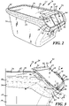
FIG. 2 depicts the center console and docking station ofFIG. 1 with a mobile device installed; and -
FIG. 3 shows the docking station ofFIGS. 1 and2 in a tilted position. - Described herein is a docking station having a more integrated and streamlined appearance within a vehicle interior cabin. In an advantageous embodiment, a vehicle interior panel, such as an instrument panel or a center console, includes the docking station integrated with an in-vehicle support substrate. To achieve a more streamlined appearance, the docking station is strategically recessed within the in-vehicle support substrate, and is able to tilt between a fully recessed position and a tilted position to promote user accessibility. Decorative coverings can be selectively implemented in certain locations to improve the vehicle aesthetics, compared to more typical aftermarket docking stations. Moreover, certain features, such as strategically located ambient lighting within an adjustable height bracket, can create a more intuitively useable docking station without detracting from the overall look and feel of the interior cabin.
-
FIG. 1 is a partial perspective view of aninterior cabin 10 for avehicle 12 having a vehicleinterior panel 14 with an in-vehicle support substrate 16 and adocking station 18 for a mobile device. Thedocking station 18 is integrated with the in-vehicle support substrate 16, which in this embodiment, is acenter console 20. Thus, theinterior panel 14 in the illustrated embodiment comprises thecenter console 20 of thevehicle 12. Theconsole 20 is typically employed adjacent individual seats in a vehicle passenger cabin, such as between thedriver seat 22 and thepassenger seat 24 in a front row of seating or between passenger seats in another row of seating. Such consoles can offer a restingsurface 26, which may provide armrests and/or table-top like surfaces to vehicle occupants. In some embodiments, other features are included, such as extra cushions, storage compartments, cup holders, etc., which help provide other conveniences for vehicle occupants. While the discussion herein is focused on thecenter console 20 implementation, other interior panels for vehicle components may be integrated with thedocking station 18 described herein, such as one or more panels for another armrest, adoor panel 28, or theinstrument panel 30, to cite a few examples. - The in-
vehicle support substrate 16 includes acarrier 32 that is the physical support layer of thepanel 14, and a first decorative covering 34 covering all or a portion of thecarrier 32. Thecarrier 32 is typically the most rigid of the illustrated layers of the multi-layer assembly and thereby provides structural support for the overlying decorative covering layer(s) at desired locations within thevehicle 12. Thecarrier 32 has anouter surface 36 that faces towards theinterior cabin 10 and toward an inner surface of thedecorative covering 34. The inner surface or theouter surface 36 of thecarrier 32 can include various bosses, ribs, grooves, etc. that impart structural benefits and/or promote attachment to other components of thevehicle 12. Fiberglass-reinforced polypropylene having a thickness of 1.6 mm to 4 mm is one example of asuitable carrier 32, but various other types of materials and material combinations and/or different thickness ranges can be employed in a similar manner (e.g., ABS and/or PC). Thesupport substrate 16 is configured for in-vehicle operation, either by forming a structural component of thevehicle 12, being directly integrated with a vehicle component in theinterior cabin 10, or providing some other vehicle-based functionality besides just holding a mobile device. - The
support substrate 16 includes the firstdecorative layer 34, and this embodiment also has a seconddecorative layer 38 lining another portion of thecarrier 32. Bothdecorative layers decorative side 40, which is the side of thepanel 14 lining the interior of thepassenger cabin 10 when installed in thevehicle 12. In this embodiment, the firstdecorative layer 34 lines an upperouter perimeter 42 of theconsole 20. In some embodiments, the firstdecorative layer 34 lines the entirety of the in-vehicle support substrate. In other embodiments, such as that illustrated, the firstdecorative layer 34 only covers a portion of thecarrier 32. One or more other portions may then be left uncovered, or covered in one or more different decorative layers. For example, the seconddecorative layer 38 is located on theresting surface 26 and the mobiledevice docking station 18. Eachdecorative layer - The
decorative coverings decorative covering decorative covering 34 is a softer material, such as a foamed polymeric layer, a fabric or natural skin layer, whereas the second decorative covering 38 is a more rigid material, such as wood veneer. This particular arrangement ofdecorative coverings - Adhesive or bonding layers can be included between two or more of the various layers or components of the
interior panel 14. Further, other layers may be included in addition to those particularly described, such as one or more protective outer layers on thedecorative side 40, fabric interlayers, conductive electronic layers, or other functional and/or aesthetic layers. In some embodiments, a foam layer is included under the firstdecorative layer 34 to create a softer feeling surface. - The
docking station 18 is integrated within the vehicleinterior panel 14 through tiltable attachment to the in-vehicle support substrate 16. The aesthetic of thedocking station 18 can be strategically designed to better match the overall look and feel of theinterior cabin 10. Further, thesupport substrate 16 and thedocking station 18 can be precisely built and integrated within thecenter console 20 in particular to help facilitate intuitive user use. As shown inFIGS. 2 and 3 , a number of differentmobile devices 44 can be accommodated, withFIG. 2 showing anexample phone 46 for the mobile device andFIG. 3 showing anexample tablet 48 for the mobile device. -
FIG. 1 shows thedocking station 18 in a fully recessedresting position 50. The resting position does not have amobile device 44 loaded in thedocking station 18. Thedocking station 18 is advantageously faced toward arear seating area 52, so passengers behind theconsole 20 can reach and stow amobile device 44 easily. In some embodiments, more than onemobile device 44 may be stowed on thedocking station 18 at one time.FIG. 2 shows thedocking station 18 is a fully recessed loadedposition 54 with thephone 46 as the loadedmobile device 44. Thisposition 54 is similar to the fully recessedresting position 50, as thedocking station 18 is fully recessed within thesupport substrate 16 in both. However,FIG. 2 shows amobile device 44 loaded in thedocking station 18.FIG. 3 illustrates a tiltedposition 56 for thedocking station 18. In some embodiments, this tiltedposition 56 can be accomplished either when thedocking station 18 is loaded withmobile device 44, or unloaded at rest. The fully recessedpositions position 56 are detailed further below. - The
docking station 18 includes atop edge 58, abottom wall 60, and areception surface 62 between the top edge and the bottom wall. Top and bottom are used herein to locate things as being closer to the roof ofvehicle 12 or closer to the floor of the vehicle, respectively.FIGS. 1 and2 show thetop edge 58 and thereception surface 62, but in the tiltedposition 56 shown inFIG. 3 , the top edge and reception surface are not visible because of the position of thedocking station 18 and the size of themobile device 44, respectively. Thedocking station 18 further includes a number of optional components such as anadjustable height bracket 64, amechanical lock 66 for the bracket, anambient light 68 integrated within the bracket, and a wireless charger 70. Thedocking station 18 may also include one or more chargingports support substrate 16, but may instead or additionally be included as part of the docking station itself. These optional sub-components are detailed further below. - The
bottom wall 60 in the illustrated embodiments has a saddle or cradle-like structure to help retain themobile device 44 while being easily recessed within thesupport substrate 16. Thebottom wall 60 has anouter surface 76 that is exposed when thedocking station 18 is in the tiltedposition 56, but in either of the fully-recessedpositions outer surface 76 is non-visible within theinterior cabin 10 and wholly recessed within thesupport substrate 16.FIG. 3 more clearly shows the saddle structure of thebottom wall 60, and shows that theouter surface 76 of the bottom wall extends into aside wall 78 and visibleside tilt surface 80. Each side of thedocking station 18 includes a pie-piece shapedside wall 78 and visibleside tilt surface 80, but only one side is visible in the view ofFIG. 3 . Eachside wall 78 andside tilt surface 80 directly face aseat vehicle 12 when in the tiltedposition 56. - The
bottom wall 60 and eachside wall 78 may be comprised of arigid substrate 82 which is then covered by the firstdecorative covering 34. This particular arrangement, where thedecorative covering 34 used on thebottom wall 60 andside wall 78 is the same as the decorative covering used on the in-vehicle support substrate 16, can enhance the aesthetic of thevehicle 12 by making thedocking station 18 more integrated with the vehicleinterior panel 14. Thesubstrate 82 may be made of the same material and in accordance with the teachings relating to thecarrier 32, and then covered in a decorative covering. In some implementations, the decorative covering used on theouter surface 76 of thebottom wall 60 and theside wall 78 is not the same as thedecorative covering 34 used on the in-vehicle support substrate, but again, matching these decorative coverings can be easier to manufacture and can improve the look and feel of thedocking station 18. - The
bottom wall 60 also includes aportion 84 configured to hold themobile device 44. Theportion 84 includes a u-shaped, chromed retaininggroove 86 that projects outwardly from thereception surface 62. While using a chrome material for at least a portion of the retaininggroove 86 can improve the attractiveness of thedocking station 18, other materials are certainly possible. For example, the retaininggroove 86, given its position adjacent thereception surface 62, may be made from the seconddecorative layer 38 as well (e.g., wood veneer). The retaininggroove 86 may be located in thebottom wall 60 exclusively, or it may extend all the way up eachside wall 78. Thegroove 86 acts as a bezel in this embodiment to frame the lower portion of thedocking station 86. Thefirst portion 84 which has the retaininggroove 86 is configured to directly contact themobile device 44, whereas asecond portion 88, on an opposing face of thebottom wall 60, is configured to be recessed in thesupport substrate 16, no matter what the position. An exposedportion 90, also along theouter surface 76 of thebottom wall 60, is visible within theinterior cabin 10 in the tiltedposition 56. Together, the second recessedportion 88 of thebottom wall 60 and the exposedportion 90, make up theouter surface 76. - To achieve the tilted
position 56, a pivotingfriction hinge 92 can be used near thetop edge 58. Locating thehinge 92 near thetop edge 58 can advantageously increase the tilt angle θ as compared to hinge locations located closer to thebottom wall 60 than what is illustrated. As used herein, near thetop edge 58 means that the hinge point is located closer to the top edge than to thebottom wall 60. The pivotingfriction hinge 92 provides for rotation of thedocking station 18 about the axis A. Other hinge types for effectuating tilting are certainly possible, but use of a friction hinge can be beneficial as it can hold thedocking station 18 at a desired tilt angle θ. Advantageously, the tilt angle θ between the tiltedposition 56 and the fully recessedposition rear seating area 52, and can be adjusted by the user to account for glare, height of the user, etc. The desired range for the tilt angle θ however, may depend on the position of thedocking station 18 at one of the fully recessedpositions sloped reception surface 62 may have a smaller range for the tilt angle, whereas a more perpendicularly oriented reception surface with respect to the structure of theconsole 20 may have a larger range for the tilt angle. A space can be provided behind thetop edge 58 to provide room for tilting, or there may be some downward motion at thehinge point 92 that occurs when thebottom wall 60 rotates outward. - The
reception surface 62 defines an area exposed to theinterior cabin 10 of thevehicle 12 where the user can intuitively place themobile device 44. Thereception surface 62 is generally bounded by thetop edge 58, theside walls 78, and thebottom wall 60. Thereception surface 62 is advantageously a more planar, rigid structure, and includes the second decorative covering 38 (e.g., wood veneer). The planar structure may facilitate improved wireless charging, for example. In some embodiments, a rubberized or gripping material may be used for all or some of thereception surface 62. For example, rubber edges in sections of about 1 mm long could create sidewalls to help reduce lateral movement of themobile device 44. Preferably, thereception surface 62 is available to a user whether thedocking station 18 is in a fully recessedposition position 56. This arrangement can promote accessibility of thedocking station 18. - An
adjustable height bracket 64 can be included to promote stable retention of a variety of differently sizedmobile devices 44 at thedocking station 18. Theadjustable height bracket 64 includes anoverhang 94 that spans betweensliders 96, 98 (seeFIG. 2 ). In some embodiments, theoverhang 94 may be located on a single slider. Including twosliders overhang 94 can include a rubberized material to further enhance retention, and a decorative covering can be used on the surface exposed to theinterior cabin 10. In some embodiments, theoverhang 94 may be adjustable to accommodatemobile devices 46 of varying thicknesses. - The
adjustable height bracket 64 in the illustrated embodiment includes amechanical lock 66 that retains theoverhang 94 in the restingposition 50. Depressing or switching themechanical lock 66 can release a detent or the like that retains spring-loaded or otherwise biasedsliders sliders docking station 18. In yet other embodiments, there may be no mechanical advantage used to help ease the change inrespective positions - An ambient
light source 68, as shown schematically inFIG. 1 , can be included to help a user intuitively guide themobile device 44 to thedocking station 18 and/or the wireless charger 70. Thelight source 68 can be powered by a vehicle-based power source, along with the wireless charger 70. Thelight source 68 can be any operable light source (e.g., fiber optic, fluorescent or incandescent bulb, light emitting diode (e.g., LED or OLED), etc.), the position of which may be at least partially dictated by the structure of thepanel 14. For example, instead of being integrated with theadjustable height bracket 64, light may be emitted from and around the retaininggroove 86. Thelight source 68 may only provide a single light color, or it may provide multiple colors. - In some embodiments, a wireless charger 70 can be included behind the
reception surface 62 to wirelessly charge themobile device 44. The range of the wireless charger 70 generally defines the size and shape of the wireless charging area on thedecorative side 40 of the decorative layer 38 (along with other factors, including but not limited to, the ability of the materials of thepanel 14 to allow for the transmission of wireless power). The wireless charger 70 can be an integral component of thepanel 14, or it may be separately provided beneath the panel when installed in thevehicle 12. The wireless charger 70 typically consists of one or more coils and electronics. It may be advantageous to embed the coils into the panel 14 (e.g., into thesubstrate 82 or in-between layers) so that they are closer to thedecorative side 40 of thedecorative layer 38, which can increase the size of the wireless charging area on thereception surface 62. The wireless charger 70 can be powered by a vehicle-based power source and may further include haptic feedback capability, such as a piezoelectric oscillator that causes vibrations to be induced in thepanel 14 when triggered by touch, proximity, or other input. - In some embodiments, other power sources may be included on or near the
panel 14, such as chargingports ports ports console 20. - It is to be understood that the foregoing is a description of one or more embodiments of the invention. The invention is not limited to the particular embodiment(s) disclosed herein, but rather is defined solely by the claims below. Furthermore, the statements contained in the foregoing description relate to particular embodiments and are not to be construed as limitations on the scope of the invention or on the definition of terms used in the claims, except where a term or phrase is expressly defined above. Various other embodiments and various changes and modifications to the disclosed embodiments) will become apparent to those skilled in the art. All such other embodiments, changes, and modifications are intended to come within the scope of the appended claims.
- As used in this specification and claims, the terms "e.g.," "for example," "for instance," "such as," and "like," and the verbs "comprising," "having," "including," and their other verb forms, when used in conjunction with a listing of one or more components or other items, are each to be construed as open-ended, meaning that the listing is not to be considered as excluding other, additional components or items. Other terms are to be construed using their broadest reasonable meaning unless they are used in a context that requires a different interpretation. In addition, the term "and/or" is to be construed as an inclusive OR. Therefore, for example, the phrase "A, B, and/or C" is to be interpreted as covering all the following: "A"; "B"; "C"; "A and B"; "A and C"; "B and C"; and "A, B, and C."
Claims (15)
- A vehicle interior panel (14), comprising:a support substrate (16) configured for in-vehicle operation; anda docking station (18) for a mobile device, the docking station (18) comprising:a top edge (58);a bottom wall (60); anda reception surface (62) for the mobile device between the top edge (58) and the bottom wall (60), wherein the reception surface (62) is pivotably attached with respect to the support substrate (16), wherein a first portion (84) of the bottom wall (60) is configured to hold the mobile device, and wherein a second portion (88) of the bottom wall (60) is configured to remain recessed within the support substrate (16) when the docking station (18) is in a tilted position.
- The vehicle interior panel of claim 1, wherein an outer surface (76) of the bottom wall (60) is completely covered by the support substrate (16) when the docking station (18) is in a fully recessed position.
- The vehicle interior panel of claim 2, wherein the reception surface (62) is accessible for use in the fully recessed position.
- The vehicle interior panel of claim 1, wherein the docking station (18) comprises a side tilt surface (80) that extends from the bottom wall (60).
- The vehicle interior panel of claim 4, wherein the side tilt surface (80) has a substrate and a first decorative covering (34), and wherein the side tilt surface (80) is only visible within an interior passenger cabin (10) when the docking station (18) is in the tilted position.
- The vehicle interior panel of claim 5, wherein the first decorative covering (34) covers an outer surface (76) of the bottom wall (60) and at least part of the support substrate (16).
- The vehicle interior panel of claim 4, wherein a second decorative covering (38) covers the reception surface (62).
- The vehicle interior panel of claim 7, wherein the first decorative covering (34) is a polymeric, fabric, or natural skin layer and the second decorative covering (38) is a wood veneer layer.
- The vehicle interior panel of claim 1, wherein a pivoting hinge (92) is located at or near the top edge of the docking station (18).
- The vehicle interior panel of claim 1, wherein the first portion (34) of the bottom wall (60) of the docking station includes a retaining groove (86).
- The vehicle interior panel of claim 1, wherein the docking station (18) includes an adjustable height bracket (64).
- The vehicle interior panel of claim 11, wherein the adjustable height bracket (64) includes an ambient light (68).
- The vehicle interior panel of claim 1, wherein a wireless charger (70) for the mobile device is located behind the reception surface (16).
- A center console comprising the vehicle interior panel of claim 1, wherein the docking station (18) faces a rear seating area (52) of an interior passenger cabin (10).
- The center console of claim 14, wherein a tilt angle between the tilted position (56) and a fully recessed position (50, 52) is between 15° and 20°, inclusive.
Applications Claiming Priority (1)
| Application Number | Priority Date | Filing Date | Title |
|---|---|---|---|
| US17/380,691 US11787348B2 (en) | 2021-07-20 | 2021-07-20 | Vehicle interior panel having a docking station for a mobile device |
Publications (1)
| Publication Number | Publication Date |
|---|---|
| EP4122772A1 true EP4122772A1 (en) | 2023-01-25 |
Family
ID=82458610
Family Applications (1)
| Application Number | Title | Priority Date | Filing Date |
|---|---|---|---|
| EP22184466.5A Pending EP4122772A1 (en) | 2021-07-20 | 2022-07-12 | Vehicle interior panel having a docking station for a mobile device |
Country Status (3)
| Country | Link |
|---|---|
| US (1) | US11787348B2 (en) |
| EP (1) | EP4122772A1 (en) |
| CN (1) | CN218616515U (en) |
Families Citing this family (3)
| Publication number | Priority date | Publication date | Assignee | Title |
|---|---|---|---|---|
| TWI762422B (en) * | 2021-09-22 | 2022-04-21 | 緯創資通股份有限公司 | Set of electrical device, stand thereof and pivoting mechanism thereof |
| US20240416842A1 (en) * | 2023-06-15 | 2024-12-19 | Ford Global Technologies, Llc | Vehicle console having deployable device holder |
| DE102023119132B4 (en) * | 2023-07-19 | 2025-02-13 | Novem Car Interior Design Gmbh | cover element for a center console |
Citations (5)
| Publication number | Priority date | Publication date | Assignee | Title |
|---|---|---|---|---|
| US20070222248A1 (en) * | 2006-03-21 | 2007-09-27 | Be Aerospace, Inc. | Holster for portable ife device |
| US20140124644A1 (en) * | 2012-11-02 | 2014-05-08 | Avionics Support Group, Inc. | Cradle assembly for a tablet |
| DE102012024430A1 (en) | 2012-12-14 | 2014-06-18 | GM Global Technology Operations LLC (n. d. Gesetzen des Staates Delaware) | Central armrest for vehicle e.g. passenger car, has pusher that comprises receiving unit for electronic device and pivoting device that is adapted to receiving unit about pivot axis to pivot |
| US9788021B2 (en) * | 2015-02-20 | 2017-10-10 | Panasonic Avionics Corporation | Display system for a vehicle entertainment system |
| US9880962B2 (en) * | 2012-10-29 | 2018-01-30 | TMI Products, Inc. | Vehicle entertainment assemblies and systems |
Family Cites Families (10)
| Publication number | Priority date | Publication date | Assignee | Title |
|---|---|---|---|---|
| US6739654B1 (en) * | 2003-04-24 | 2004-05-25 | Hexa-Chain Co., Ltd. | Headrest-mount display mounting structure |
| DE202011110849U1 (en) * | 2010-01-28 | 2016-11-03 | Kinetix Ag | Device for attaching a tablet computer |
| EP2917105B1 (en) * | 2012-11-12 | 2019-06-19 | Safran Seats USA LLC | Integrated keyboard tray |
| DE202013104059U1 (en) | 2013-09-06 | 2013-10-25 | Baseline Vertrieb Ohg | Mounting arrangement of a tablet computer in a motor vehicle |
| CN204161242U (en) | 2014-11-03 | 2015-02-18 | 陈工 | Vehicle-mounted flat electronic device stand |
| WO2018100407A1 (en) | 2016-11-29 | 2018-06-07 | Faurecia Interior Systems India Private Limited | Support device for mobile electronic devices |
| US20190381950A1 (en) | 2018-06-17 | 2019-12-19 | Alexander Morrison | Methods, systems and apparatus for an in-vehicle flexible viewing platform |
| CN112424024B (en) * | 2018-07-20 | 2023-03-24 | 阿莫善斯有限公司 | Wirelessly chargeable cup holder for automobile |
| FR3085641B1 (en) | 2018-09-10 | 2020-10-16 | Psa Automobiles Sa | MOUNTING SYSTEM FOR A PORTABLE ELECTRONIC DEVICE IN A VEHICLE INTERIOR |
| US11358531B2 (en) | 2019-01-14 | 2022-06-14 | Motherson Innovations Company Limited | Multifunctional center console system for a vehicle |
-
2021
- 2021-07-20 US US17/380,691 patent/US11787348B2/en active Active
-
2022
- 2022-07-12 EP EP22184466.5A patent/EP4122772A1/en active Pending
- 2022-07-20 CN CN202221906488.0U patent/CN218616515U/en active Active
Patent Citations (5)
| Publication number | Priority date | Publication date | Assignee | Title |
|---|---|---|---|---|
| US20070222248A1 (en) * | 2006-03-21 | 2007-09-27 | Be Aerospace, Inc. | Holster for portable ife device |
| US9880962B2 (en) * | 2012-10-29 | 2018-01-30 | TMI Products, Inc. | Vehicle entertainment assemblies and systems |
| US20140124644A1 (en) * | 2012-11-02 | 2014-05-08 | Avionics Support Group, Inc. | Cradle assembly for a tablet |
| DE102012024430A1 (en) | 2012-12-14 | 2014-06-18 | GM Global Technology Operations LLC (n. d. Gesetzen des Staates Delaware) | Central armrest for vehicle e.g. passenger car, has pusher that comprises receiving unit for electronic device and pivoting device that is adapted to receiving unit about pivot axis to pivot |
| US9788021B2 (en) * | 2015-02-20 | 2017-10-10 | Panasonic Avionics Corporation | Display system for a vehicle entertainment system |
Also Published As
| Publication number | Publication date |
|---|---|
| US11787348B2 (en) | 2023-10-17 |
| US20230026523A1 (en) | 2023-01-26 |
| CN218616515U (en) | 2023-03-14 |
Similar Documents
| Publication | Publication Date | Title |
|---|---|---|
| US11590903B1 (en) | Vehicle seat having a docking station for a mobile device | |
| US11787348B2 (en) | Vehicle interior panel having a docking station for a mobile device | |
| US20120230047A1 (en) | Low profile switching and lighting integration within an interior vehicle component | |
| US7192070B2 (en) | Vehicle console with armrest extension | |
| US6726267B2 (en) | Console assembly | |
| US20200406823A1 (en) | Half-movable console for vehicle | |
| US7591498B2 (en) | Sliding console | |
| JP5247722B2 (en) | Integrated soft central floor console | |
| US7938470B2 (en) | Removable stowage device | |
| US7798548B2 (en) | Soft composite trim panel for a vehicle interior | |
| US10076986B2 (en) | Vehicle seat | |
| EP3475122B1 (en) | Trim part comprising a decorative element comprising a lighting portion | |
| US9283876B2 (en) | Head restraint with storage | |
| US20070085363A1 (en) | Console assembly for a vehicle | |
| US11866010B2 (en) | Vehicle interior panel assembly having a stowage tray for a mobile device | |
| US20230322169A1 (en) | Cladding Part Having a Textile Covering | |
| US20240416842A1 (en) | Vehicle console having deployable device holder | |
| KR100558532B1 (en) | Table installed on the seat of the car | |
| JP7828538B2 (en) | Interior materials for vehicles | |
| US7267396B2 (en) | Removable storage module for vehicle | |
| JP7794091B2 (en) | Vehicle interior materials | |
| JP7794090B2 (en) | Vehicle interior materials | |
| CN219706889U (en) | Rear seat armrest decorative plate structure with storage box and armrest box | |
| JP7379871B2 (en) | Vehicle lighting system | |
| US20060163913A1 (en) | Removable quarter panels for open-air style vehicles |
Legal Events
| Date | Code | Title | Description |
|---|---|---|---|
| PUAI | Public reference made under article 153(3) epc to a published international application that has entered the european phase |
Free format text: ORIGINAL CODE: 0009012 |
|
| STAA | Information on the status of an ep patent application or granted ep patent |
Free format text: STATUS: THE APPLICATION HAS BEEN PUBLISHED |
|
| AK | Designated contracting states |
Kind code of ref document: A1 Designated state(s): AL AT BE BG CH CY CZ DE DK EE ES FI FR GB GR HR HU IE IS IT LI LT LU LV MC MK MT NL NO PL PT RO RS SE SI SK SM TR |
|
| STAA | Information on the status of an ep patent application or granted ep patent |
Free format text: STATUS: REQUEST FOR EXAMINATION WAS MADE |
|
| 17P | Request for examination filed |
Effective date: 20230707 |
|
| RBV | Designated contracting states (corrected) |
Designated state(s): AL AT BE BG CH CY CZ DE DK EE ES FI FR GB GR HR HU IE IS IT LI LT LU LV MC MK MT NL NO PL PT RO RS SE SI SK SM TR |
|
| STAA | Information on the status of an ep patent application or granted ep patent |
Free format text: STATUS: EXAMINATION IS IN PROGRESS |
|
| 17Q | First examination report despatched |
Effective date: 20241212 |