EP4122749B1 - Charging ports of an electric straddled vehicle - Google Patents
Charging ports of an electric straddled vehicle Download PDFInfo
- Publication number
- EP4122749B1 EP4122749B1 EP22186017.4A EP22186017A EP4122749B1 EP 4122749 B1 EP4122749 B1 EP 4122749B1 EP 22186017 A EP22186017 A EP 22186017A EP 4122749 B1 EP4122749 B1 EP 4122749B1
- Authority
- EP
- European Patent Office
- Prior art keywords
- charging port
- battery
- disposed
- charging
- electric vehicle
- Prior art date
- Legal status (The legal status is an assumption and is not a legal conclusion. Google has not performed a legal analysis and makes no representation as to the accuracy of the status listed.)
- Active
Links
Images


Classifications
-
- B—PERFORMING OPERATIONS; TRANSPORTING
- B62—LAND VEHICLES FOR TRAVELLING OTHERWISE THAN ON RAILS
- B62K—CYCLES; CYCLE FRAMES; CYCLE STEERING DEVICES; RIDER-OPERATED TERMINAL CONTROLS SPECIALLY ADAPTED FOR CYCLES; CYCLE AXLE SUSPENSIONS; CYCLE SIDECARS, FORECARS, OR THE LIKE
- B62K11/00—Motorcycles, engine-assisted cycles or motor scooters with one or two wheels
-
- B—PERFORMING OPERATIONS; TRANSPORTING
- B60—VEHICLES IN GENERAL
- B60L—PROPULSION OF ELECTRICALLY-PROPELLED VEHICLES; SUPPLYING ELECTRIC POWER FOR AUXILIARY EQUIPMENT OF ELECTRICALLY-PROPELLED VEHICLES; ELECTRODYNAMIC BRAKE SYSTEMS FOR VEHICLES IN GENERAL; MAGNETIC SUSPENSION OR LEVITATION FOR VEHICLES; MONITORING OPERATING VARIABLES OF ELECTRICALLY-PROPELLED VEHICLES; ELECTRIC SAFETY DEVICES FOR ELECTRICALLY-PROPELLED VEHICLES
- B60L50/00—Electric propulsion with power supplied within the vehicle
- B60L50/50—Electric propulsion with power supplied within the vehicle using propulsion power supplied by batteries or fuel cells
- B60L50/60—Electric propulsion with power supplied within the vehicle using propulsion power supplied by batteries or fuel cells using power supplied by batteries
- B60L50/66—Arrangements of batteries
-
- B—PERFORMING OPERATIONS; TRANSPORTING
- B60—VEHICLES IN GENERAL
- B60L—PROPULSION OF ELECTRICALLY-PROPELLED VEHICLES; SUPPLYING ELECTRIC POWER FOR AUXILIARY EQUIPMENT OF ELECTRICALLY-PROPELLED VEHICLES; ELECTRODYNAMIC BRAKE SYSTEMS FOR VEHICLES IN GENERAL; MAGNETIC SUSPENSION OR LEVITATION FOR VEHICLES; MONITORING OPERATING VARIABLES OF ELECTRICALLY-PROPELLED VEHICLES; ELECTRIC SAFETY DEVICES FOR ELECTRICALLY-PROPELLED VEHICLES
- B60L53/00—Methods of charging batteries, specially adapted for electric vehicles; Charging stations or on-board charging equipment therefor; Exchange of energy storage elements in electric vehicles
- B60L53/10—Methods of charging batteries, specially adapted for electric vehicles; Charging stations or on-board charging equipment therefor; Exchange of energy storage elements in electric vehicles characterised by the energy transfer between the charging station and the vehicle
- B60L53/11—DC charging controlled by the charging station, e.g. mode 4
-
- B—PERFORMING OPERATIONS; TRANSPORTING
- B60—VEHICLES IN GENERAL
- B60L—PROPULSION OF ELECTRICALLY-PROPELLED VEHICLES; SUPPLYING ELECTRIC POWER FOR AUXILIARY EQUIPMENT OF ELECTRICALLY-PROPELLED VEHICLES; ELECTRODYNAMIC BRAKE SYSTEMS FOR VEHICLES IN GENERAL; MAGNETIC SUSPENSION OR LEVITATION FOR VEHICLES; MONITORING OPERATING VARIABLES OF ELECTRICALLY-PROPELLED VEHICLES; ELECTRIC SAFETY DEVICES FOR ELECTRICALLY-PROPELLED VEHICLES
- B60L53/00—Methods of charging batteries, specially adapted for electric vehicles; Charging stations or on-board charging equipment therefor; Exchange of energy storage elements in electric vehicles
- B60L53/10—Methods of charging batteries, specially adapted for electric vehicles; Charging stations or on-board charging equipment therefor; Exchange of energy storage elements in electric vehicles characterised by the energy transfer between the charging station and the vehicle
- B60L53/14—Conductive energy transfer
- B60L53/16—Connectors, e.g. plugs or sockets, specially adapted for charging electric vehicles
-
- B—PERFORMING OPERATIONS; TRANSPORTING
- B62—LAND VEHICLES FOR TRAVELLING OTHERWISE THAN ON RAILS
- B62J—CYCLE SADDLES OR SEATS; AUXILIARY DEVICES OR ACCESSORIES SPECIALLY ADAPTED TO CYCLES AND NOT OTHERWISE PROVIDED FOR, e.g. ARTICLE CARRIERS OR CYCLE PROTECTORS
- B62J43/00—Arrangements of batteries
- B62J43/10—Arrangements of batteries for propulsion
- B62J43/16—Arrangements of batteries for propulsion on motorcycles or the like
-
- B—PERFORMING OPERATIONS; TRANSPORTING
- B62—LAND VEHICLES FOR TRAVELLING OTHERWISE THAN ON RAILS
- B62J—CYCLE SADDLES OR SEATS; AUXILIARY DEVICES OR ACCESSORIES SPECIALLY ADAPTED TO CYCLES AND NOT OTHERWISE PROVIDED FOR, e.g. ARTICLE CARRIERS OR CYCLE PROTECTORS
- B62J45/00—Electrical equipment arrangements specially adapted for use as accessories on cycles, not otherwise provided for
-
- B—PERFORMING OPERATIONS; TRANSPORTING
- B60—VEHICLES IN GENERAL
- B60L—PROPULSION OF ELECTRICALLY-PROPELLED VEHICLES; SUPPLYING ELECTRIC POWER FOR AUXILIARY EQUIPMENT OF ELECTRICALLY-PROPELLED VEHICLES; ELECTRODYNAMIC BRAKE SYSTEMS FOR VEHICLES IN GENERAL; MAGNETIC SUSPENSION OR LEVITATION FOR VEHICLES; MONITORING OPERATING VARIABLES OF ELECTRICALLY-PROPELLED VEHICLES; ELECTRIC SAFETY DEVICES FOR ELECTRICALLY-PROPELLED VEHICLES
- B60L2200/00—Type of vehicles
- B60L2200/12—Bikes
-
- B—PERFORMING OPERATIONS; TRANSPORTING
- B62—LAND VEHICLES FOR TRAVELLING OTHERWISE THAN ON RAILS
- B62K—CYCLES; CYCLE FRAMES; CYCLE STEERING DEVICES; RIDER-OPERATED TERMINAL CONTROLS SPECIALLY ADAPTED FOR CYCLES; CYCLE AXLE SUSPENSIONS; CYCLE SIDECARS, FORECARS, OR THE LIKE
- B62K2202/00—Motorised scooters
-
- Y—GENERAL TAGGING OF NEW TECHNOLOGICAL DEVELOPMENTS; GENERAL TAGGING OF CROSS-SECTIONAL TECHNOLOGIES SPANNING OVER SEVERAL SECTIONS OF THE IPC; TECHNICAL SUBJECTS COVERED BY FORMER USPC CROSS-REFERENCE ART COLLECTIONS [XRACs] AND DIGESTS
- Y02—TECHNOLOGIES OR APPLICATIONS FOR MITIGATION OR ADAPTATION AGAINST CLIMATE CHANGE
- Y02T—CLIMATE CHANGE MITIGATION TECHNOLOGIES RELATED TO TRANSPORTATION
- Y02T10/00—Road transport of goods or passengers
- Y02T10/60—Other road transportation technologies with climate change mitigation effect
- Y02T10/70—Energy storage systems for electromobility, e.g. batteries
Definitions
- the DC charging port is disposed at a position near the battery, the volume of an assembly including the DC charging port and the battery can be reduced. With this, both the battery and the DC charging port can be easily disposed in the center tunnel portion.
- the AC charging port 12 is provided in the front portion of the vehicle body 2.
- the body cover 24 includes a front cowl 27 ( FIG. 4 ) that covers a part of the front portion of the two-wheeled electric vehicle 1.
- the AC charging port 12 is disposed through the front cowl 27.
- the AC charging port 12 is provided with a cover 112 that prevents intrusion of rainwater and dust.
- the DC charging port 11 is also provided with a cover that prevents the intrusion of rainwater and dust.
- the BMS 33 controls charging operation and discharging operation of the battery 3. Switching between the charging and the discharging of the battery 3, and switching of the current to be used for the charging can be made, for example, in response to switching of a relay switch by the BMS 33.
- the BMS 33 performs control to supply a current that is input through the DC charging port 11 and via the harness 34 to the plurality of battery cells 35.
- the BMS 33 performs control to supply a current that is input from the onboard charger 4 via the harness 46 to the plurality of battery cells 35.
- a current is output from the battery 3 to the MCU 6, the BMS 33 performs control to cause the plurality of battery cells 35 to output currents.
- the current output from the battery 3 is supplied to the MCU 6 via a harness 316.
- the DC charging port 11 can be disposed at a position between the front end portion 3f of the battery casing 31 and a rear end portion 3r of the battery casing 31.
- the AC charging port 12 can be disposed frontward of the front end portion 3f of the battery casing 31, or rearward of the rear end portion 3r of the battery casing 31. Since the DC charging port 11 is disposed at a position near the battery 3, any harness with a large cross-sectional area can be shortened, and the space required for accommodating the harness can be reduced. Since the DC charging port 11 and the AC charging port 12 are disposed away from each other, the rider can easily distinguish these two kinds of charging ports from each other.
- the AC charging port 12 may be disposed in each of the front portion and the rear portion of the two-wheeled electric vehicle 1. With this, in the parking space, whether the charging external power source is disposed in front of or behind the two-wheeled electric vehicle 1, the charging connector can be easily connected to the AC charging port 12.
- a straddled electric vehicle 1 includes:
- the rider can easily distinguish these two kinds of charging ports from each other. With this, for example, mis-insertion of the charging connectors can be suppressed.
- the rider can easily distinguish these two kinds of charging ports from each other. With this, for example, mis-insertion of the charging connectors can be suppressed.
- the center tunnel portion 25 is located at the position that is accessible to the rider. Since the DC charging port 11 is disposed in the center tunnel portion 25, the rider can easily perform the charging.
- the straddled electric vehicle 1 is parked generally by being advanced into the parking space. Since the AC charging port 12 is disposed at a relatively high position in the vehicle front portion, the charging connector installed in the parking space can be easily connected to the AC charging port 12.
- the rider can easily distinguish these two kinds of charging ports from each other. With this, for example, mis-insertion of the charging connectors can be suppressed.
- the straddled electric vehicle 1 is parked generally by being advanced into the parking space. Since the AC charging port 12 is disposed at the front side in the straddled electric vehicle 1, the charging connector installed in the parking space can be easily connected to the AC charging port 12.
- the rider can easily distinguish these two kinds of charging ports from each other. With this, for example, mis-insertion of the charging connectors can be suppressed.
- the straddled electric vehicle 1 may further include an onboard charger 4 that
- the battery 3 can be charged by using the AC current received by the AC charging port 12.
- the present invention is useful particularly in the field of straddled electric vehicles that utilize an electric motor as their driving source.
Landscapes
- Engineering & Computer Science (AREA)
- Mechanical Engineering (AREA)
- Power Engineering (AREA)
- Transportation (AREA)
- Life Sciences & Earth Sciences (AREA)
- Sustainable Development (AREA)
- Sustainable Energy (AREA)
- Electric Propulsion And Braking For Vehicles (AREA)
- Charge And Discharge Circuits For Batteries Or The Like (AREA)
- Motorcycle And Bicycle Frame (AREA)
Description
- The present invention relates to a straddled electric vehicle according to the preamble of
independent claim 1 that travels by using an electric motor. Such a straddled electric vehicle can be taken from the prior art documentWO 2019/193023 A1 . - There are straddled electric vehicles that travel by using an electric motor as their driving source (see, for example,
JP 2000-253591 A - In order to charge the battery installed in a straddled electric vehicles, a charging port at which a connector of an external power source is detachable may be provided for the vehicle. However, in a straddled electric vehicle, a large number of components need to be disposed within a limited space within the vehicle body. Thus, it is not easy to secure a space in which to dispose the charging port and a harness extending from the charging port.
- It is the object of the present invention to provide straddled electric vehicle having high flexibility in use. According to the present invention said object is solved by a straddled electric vehicle having the features of
independent claim 1. Preferred embodiments are laid down in the dependent claims. Accordingly, the present invention provides a straddled electric vehicle including a plurality of charging ports. - A straddled electric vehicle according to the present teaching includes:
- a wheel;
- an electric motor that drives the wheel;
- a battery that supplies electric power to the electric motor;
- a DC charging port
- at which a connector provided on a cable extending from a first external power source to output a DC current for charging the battery is detachable, and
- which receives the DC current output from the first external power source; and
- an AC charging port
- at which a connector provided on a cable extending from a second external power source to output an AC current for charging the battery is detachable, and
- which receives the AC current output from the second external power source.
- A first distance being defined as a distance between the DC charging port and the battery is smaller than a second distance being defined as a distance between the AC charging port and the battery.
- The straddled electric vehicle according to a certain embodiment according to the present teaching includes two kinds of charging ports, that is, the DC charging port and the AC charging port. Generally, a DC current to be output from an external power source is used for rapid charging, such that a large current flows during the charging; for this reason, a thick harness having a large cross-sectional area is used as a harness that connects the DC charging port and the battery to each other. Since the DC charging port is disposed at a position near the battery, the harness with a large cross-sectional area can be shortened, and the space required for accommodating the harness can be reduced. In the straddled electric vehicle, a large number of components need to be disposed within a limited space in a vehicle body. Thus, the space saving is significantly advantageous. In addition, since the harness having a large cross-sectional area can be shortened, weight reduction and cost reduction can be achieved.
- In one embodiment, the battery may have a battery casing.
- In one embodiment, the harness extending from the DC charging port may be directly inserted in the battery casing.
- Generally, connectors capable of delivering a large current are expensive. Since no connector for connecting the harness extending from the DC charging port and the battery to each other is provided, cost reduction can be achieved.
- In one embodiment,
- the battery may have the battery casing;
- along a vehicle front-rear direction, the DC charging port may be disposed at a position between a front end portion of the battery casing and a rear end portion of the battery casing; and
- along the vehicle front-rear direction, the AC charging port may be disposed frontward of the front end portion of the battery casing, or rearward of the rear end portion of the battery casing.
- Since the DC charging port is disposed at a position near the battery, any harness with a large cross-sectional area can be shortened, and the space required for accommodating the harness can be reduced.
- Since the DC charging port and the AC charging port are disposed away from each other, a rider can easily distinguish these two kinds of charging ports from each other. With this, for example, mis-insertion of the charging connectors can be suppressed.
- In one embodiment,
- the straddled electric vehicle may further include a body frame including a head pipe;
- along the vehicle front-rear direction, the AC charging port may be disposed frontward of the head pipe; and
- along the vehicle front-rear direction, the DC charging port may be disposed rearward of the head pipe.
- Since the DC charging port and the AC charging port are disposed away from each other, the rider can easily distinguish these two kinds of charging ports from each other. With this, for example, mis-insertion of the charging connectors can be suppressed.
- In addition, during a parking maneuver, the straddled electric vehicle is parked generally by being advanced into a parking space. Since the AC charging port is disposed at the front side in the straddled electric vehicle, the charging connector installed in the parking space can be easily connected to the AC charging port.
- In one embodiment,
- the straddled electric vehicle may further include:
- a first footboard on which the rider rests a left foot;
- a second footboard on which the rider rests a right foot; and
- a body cover including a center tunnel portion located between the first footboard and the second footboard along a vehicle width direction;
- the battery may be disposed in the center tunnel portion; and
- the DC charging port may be disposed on an outer surface side of the center tunnel portion.
- Since the DC charging port is disposed at a position near the battery, the volume of an assembly including the DC charging port and the battery can be reduced. With this, both the battery and the DC charging port can be easily disposed in the center tunnel portion.
- The center tunnel portion is located at a position that is accessible to the rider. Since the DC charging port is disposed in the center tunnel portion, the rider can easily perform the charging.
- In one embodiment,
- the straddled electric vehicle may further include a front cowl that covers a part of a vehicle front portion; and
- the AC charging port may be disposed through the front cowl.
- During a parking maneuver, the straddled electric vehicle is parked generally by being advanced into the parking space. Since the AC charging port is disposed at a relatively high position in the vehicle front portion, the charging connector installed in the parking space can be easily connected to the AC charging port.
- In one embodiment,
- the battery may have the battery casing;
- along the vehicle front-rear direction, the AC charging port may be disposed frontward of the front end portion of the battery casing; and
- along the vehicle front-rear direction, the DC charging port may be disposed rearward of the front end portion of the battery casing.
- Since the DC charging port and the AC charging port are disposed away from each other, the rider can easily distinguish these two kinds of charging ports from each other. With this, for example, mis-insertion of the charging connectors can be suppressed.
- In addition, during a parking maneuver, the straddled electric vehicle is parked generally by being advanced into the parking space. Since the AC charging port is disposed at the front side in the straddled electric vehicle, the charging connector installed in the parking space can be easily connected to the AC charging port.
- In one embodiment,
- the straddled electric vehicle may further include a seat on which the rider is seated;
- along the vehicle front-rear direction, the DC charging port may be disposed frontward of a front end portion of the seat; and
- along the vehicle front-rear direction, the AC charging port may be disposed rearward of the front end portion of the seat.
- Since the DC charging port and the AC charging port are disposed away from each other, the rider can easily distinguish these two kinds of charging ports from each other. With this, for example, mis-insertion of the charging connectors can be suppressed.
- In one embodiment,
the straddled electric vehicle may further include an onboard charger that
converts the AC current received by the AC charging port to a DC current, and outputs the DC current to the battery. - With this, the battery can be charged by using the AC current received by the AC charging port.
- The straddled electric vehicle according to the present teaching includes two kinds of charging ports, that is, the DC charging port and the AC charging port. Generally, a DC current to be output from an external power source is used for rapid charging, such that a large current flows during the charging; for this reason, the thick harness having the large cross-sectional area is used as the harness that connects the DC charging port and the battery to each other. Since the DC charging port is disposed at a position near the battery, the harness with a large cross-sectional area can be shortened, and the space required for accommodating the harness can be reduced. In the straddled electric vehicle, a large number of components need to be disposed within the limited space in the vehicle body. Thus, the space saving is significantly advantageous. In addition, since the harness having a large cross-sectional area can be shortened, weight reduction and cost reduction can be achieved.
- In one embodiment, a harness extending from the AC charging port is directly inserted in the onboard charger and configured to supply current input from the AC charging port to the onboard charger.
- In one embodiment, a harness extending the onboard charger is directly inserted in the battery and configured to supply current output from the onboard charger to the battery.
- In one embodiment, the drive unit includes an electric motor and a motor control unit configured to control operation of the electric motor, wherein a harness extending from the battery is directly inserted in the motor control unit and configured to supply current output from the battery to the motor control unit.
-
-
FIG. 1 is a left side view illustrating a straddledelectric vehicle 1 according to an embodiment according to the present teaching. -
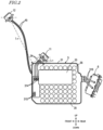
FIG. 2 is a left side view illustrating abattery 3, anMCU 6, aDC charging port 11, and anAC charging port 12 according to the embodiment. -
FIG. 3 is a right side view illustrating thebattery 3, anonboard charger 4, amotor 5, theMCU 6, and theDC charging port 11 according to the embodiment. -
FIG. 4 is a perspective view in which the straddledelectric vehicle 1 according to the embodiment is viewed obliquely from front left. -
FIG. 5 is a top view illustrating the straddledelectric vehicle 1 according to the embodiment. -
FIG. 6 is a view illustrating how thebattery 3 of the straddledelectric vehicle 1 according to the embodiment may be charged by using a DC current. -
FIG. 7 is a view illustrating how thebattery 3 of the straddledelectric vehicle 1 according to the embodiment may be charged by using an AC current. -
FIG. 8 is a view illustrating another example positioning of theAC charging port 12 according to the embodiment. -
FIG. 9 is a view illustrating still another example positioning of theAC charging port 12 according to the embodiment. - Hereinbelow, with reference to the attached drawings, an embodiment according to the present teaching is described. Like components are denoted by like reference numerals, and redundant description of such components is omitted. In the following description, the front, rear, top, bottom, right, and left correspond respectively to the front, rear, top, bottom, right, and left as viewed from a rider seated on a seat of an electric vehicle.
-
FIG. 1 is a left side view illustrating a straddledelectric vehicle 1 according to an embodiment according to the present teaching. In the example illustrated inFIG. 1 , the straddledelectric vehicle 1 is a two-wheeled electric vehicle of a scooter type. Note that the straddledelectric vehicle 1 according to an embodiment according to the present teaching is not limited to the scooter-type two-wheeled electric vehicle exemplified herein. The straddledelectric vehicle 1 according to the embodiment according to the present teaching may be two-wheeled electric vehicles of other types such as what is called an on-road type, an offroad type, and a moped type. A straddled electric vehicle refers to an arbitrary vehicle that the rider rides in a straddling manner, and hence is not limited to two-wheeled vehicles. The straddledelectric vehicle 1 may be a three-wheeled vehicle (LMW) of a type whose direction of travel is changed as the vehicle body is tilted, etc., or any other straddled electric vehicle such as an ATV (All Terrain Vehicle). The straddledelectric vehicle 1 may be a vehicle with four or more wheels. - As illustrated in
FIG. 1 , the two-wheeledelectric vehicle 1 includes avehicle body 2, abattery 3, anonboard charger 4, adrive unit 10, afront wheel 13, and arear wheel 14. For ease of understanding of the configuration of the two-wheeledelectric vehicle 1,FIG. 1 illustrates portion of the interior of the two-wheeledelectric vehicle 1 in a see-through manner. - The
vehicle body 2 has a structure including abody frame 20 and abody cover 24. Thebody frame 20 includes ahead pipe 22. A steeringshaft 19 is inserted in thehead pipe 22.Front forks 15 are provided at a lower end of the steeringshaft 19. Thefront forks 15 are capable of turning to the right and left about the steeringshaft 19 inserted in thehead pipe 22. Thefront wheel 13 is rotatably supported at lower end portions of thefront forks 15. A steering handle 18 is provided at an upper end of the steeringshaft 19. - A rear portion of the
vehicle body 2 swingingly supports aswingarm 16. Therear wheel 14 is rotatably supported by theswingarm 16. In this example, therear wheel 14 is a drive wheel, and thefront wheel 13 is a driven wheel. Aseat 17 on which the rider is seated is provided at an upper portion of thevehicle body 2. - The
battery 3 is disposed at a position between thefront wheel 13 and therear wheel 14 along the front-rear direction of thevehicle 1. Thedrive unit 10 is disposed reward of thebattery 3. Thedrive unit 10 includes anelectric motor 5 and a motor control unit (MCU) 6 that controls operation of theelectric motor 5. Thebattery 3 supplies electric power for activating theelectric motor 5. TheMCU 6 generates a driving current from an output current of thebattery 3, and outputs this driving current to theelectric motor 5. Rotation caused by theelectric motor 5 is transmitted to therear wheel 14 via, for example, a motive power transmission mechanism of a belt-drive type, whereby thevehicle 1 travels. The rotation caused by theelectric motor 5 may be transmitted to therear wheel 14 via a motive power transmission mechanism of a chain-drive type or a shaft-drive type. - A
DC charging port 11 is provided above thebattery 3. AnAC charging port 12 is provided in a front portion of thevehicle body 2.FIG. 2 is a left side view illustrating thebattery 3, theMCU 6, theDC charging port 11, and theAC charging port 12.FIG. 2 illustrates the interior of thebattery 3. - The
DC charging port 11 includes a receptacle at which a connector (plug) of an external power source that outputs a DC current for charging thebattery 3 is detachable. TheDC charging port 11 receives the DC current output from the external power source. TheDC charging port 11 is connected to thebattery 3 via aharness 34. When charging thebattery 3, the DC current output from the external power source is supplied to thebattery 3 through theDC charging port 11, whereby thebattery 3 can be charged. - The
onboard charger 4 is disposed to the right of thebattery 3.FIG. 3 is a right side view illustrating thebattery 3, theonboard charger 4, amotor 5, theMCU 6, and theDC charging port 11. With reference toFIG. 1 , theAC charging port 12 is provided in the front portion of thevehicle body 2. TheAC charging port 12 includes a receptacle at which another connector (plug) of another external power source that outputs an AC current for charging thebattery 3 is detachable. TheAC charging port 12 receives the AC current output from the other external power source. TheAC charging port 12 is connected to theonboard charger 4 via aharness 45. When charging thebattery 3, the AC current output from the other external power source is supplied to theonboard charger 4 through theAC charging port 12. Theonboard charger 4 converts the AC current to a DC current, and outputs the DC current to thebattery 3, whereby thebattery 3 can be charged. The DC current output by theonboard charger 4 is supplied to thebattery 3 via, for example, a harness 46 (FIG. 3 ). -
FIG. 4 is a perspective view in which the two-wheeledelectric vehicle 1 is viewed obliquely from front left.FIG. 5 is a top view illustrating the two-wheeledelectric vehicle 1. -
Footboards front wheel 13 and therear wheel 14 along the front-rear direction of thevehicle body 2. Thefootboard 26L, which is a footboard on which a rider rests his/her left foot, is disposed on a left-hand side along the vehicle width direction (right-left direction) of thevehicle body 2. Thefootboard 26R, which is a footboard on which a rider rests his/her right foot, is disposed on a right-hand side along the vehicle width direction of thevehicle body 2. - The body cover 24 includes a
center tunnel portion 25 located between thefootboard 26L and thefootboard 26R along the vehicle width direction. Thecenter tunnel portion 25 has a shape swelling upward relative to thefootboard 26L and thefootboard 26R at a position between thefootboards FIG. 1 , in this embodiment, thebattery 3 is disposed in thecenter tunnel portion 25. TheDC charging port 11 is disposed so as to be exposed from an upper outer surface of thecenter tunnel portion 25. - The
AC charging port 12 is provided in the front portion of thevehicle body 2. The body cover 24 includes a front cowl 27 (FIG. 4 ) that covers a part of the front portion of the two-wheeledelectric vehicle 1. In this embodiment, theAC charging port 12 is disposed through thefront cowl 27. TheAC charging port 12 is provided with acover 112 that prevents intrusion of rainwater and dust. TheDC charging port 11 is also provided with a cover that prevents the intrusion of rainwater and dust. - With reference to
FIG. 2 , thebattery 3 includes a plurality ofbattery cells 35, and abattery casing 31 that houses the plurality ofbattery cells 35. Thebattery casing 31 also houses a battery management system (BMS) 33 andelectrode terminals 314 and 315. Theharness 34 extending from theDC charging port 11 is connected to the electrode terminals 314. Theharness 46 extending from the onboard charger 4 (FIG. 3 ) is connected to theelectrode terminals 315. - The
BMS 33 controls charging operation and discharging operation of thebattery 3. Switching between the charging and the discharging of thebattery 3, and switching of the current to be used for the charging can be made, for example, in response to switching of a relay switch by theBMS 33. When charging by inputting a DC current is performed, theBMS 33 performs control to supply a current that is input through theDC charging port 11 and via theharness 34 to the plurality ofbattery cells 35. When charging by inputting an AC current is performed, theBMS 33 performs control to supply a current that is input from theonboard charger 4 via theharness 46 to the plurality ofbattery cells 35. When a current is output from thebattery 3 to theMCU 6, theBMS 33 performs control to cause the plurality ofbattery cells 35 to output currents. The current output from thebattery 3 is supplied to theMCU 6 via aharness 316. - In this embodiment, the
DC charging port 11 is disposed at a position relatively near thebattery 3, and theAC charging port 12 is disposed at a position relatively far from thebattery 3. When a distance between theDC charging port 11 and thebattery 3 is a first distance L11, and when a distance between theAC charging port 12 and thebattery 3 is a second distance L12, the first distance L11 is smaller than the second distance L12. In this case, the first distance L11 is, for example, the shortest distance from a center position of theDC charging port 11 to thebattery casing 31. The second distance L12 is, for example, the shortest distance from a center position of theAC charging port 12 to thebattery casing 31. - The first distance L11 may be the shortest distance from an end portion of the
harness 34 on the side where theDC charging port 11 exists to thebattery casing 31. In this case, the second distance L12 can be the shortest distance from an end portion of theharness 45 on the side where theAC charging port 12 exists to thebattery casing 31. - Generally, a DC current to be output from an external power source is used for rapid charging, such that a large current flows during the charging; for this reason, a thick harness having a large cross-sectional area is used as the
harness 34 that connects theDC charging port 11 and thebattery 3 to each other. Since theDC charging port 11 is disposed at a position near thebattery 3, theharness 34 with a large cross-sectional area can be shortened, and the space required for accommodating theharness 34 can be reduced. In the straddledelectric vehicle 1, a large number of components need to be disposed within a limited space in the vehicle body. Thus, the space saving is significantly advantageous. In addition, since theharness 34 having a large cross-sectional area can be shortened, weight reduction and cost reduction can be achieved. - Further, in this embodiment, the
harness 34 extending from theDC charging port 11 is not connected to thebattery 3 via a connector, but directly inserted in thebattery casing 31. Generally, connectors capable of delivering a large current are expensive. Since no connector for connecting theharness 34 extending from theDC charging port 11 and thebattery 3 to each other is provided, cost reduction can be achieved. - Since the
DC charging port 11 is disposed at a position near thebattery 3, the volume of an assembly including theDC charging port 11 and thebattery 3 can be reduced. With this, both thebattery 3 and theDC charging port 11 can be easily disposed in thecenter tunnel portion 25. -
FIG. 6 is a view illustrating how thebattery 3 of the two-wheeledelectric vehicle 1 may be charged by using a DC current. As an example of an external power source that outputs a DC current for charging thebattery 3,FIG. 6 illustrates a charging station (also referred to as a charging spot). This chargingstation 410 can be installed, for example, in a parking lot of a commercial facility. A power supply connector 412 (first connector) is provided at one end of a (first)cable 411 extending from the chargingstation 410. Charging can be performed by connecting thepower supply connector 412 to theDC charging port 11 of the two-wheeledelectric vehicle 1. Thecenter tunnel portion 25 is located at a position that is accessible to the rider. Since theDC charging port 11 is disposed in thecenter tunnel portion 25, the rider can easily perform the charging. - In this embodiment, the
DC charging port 11 and theAC charging port 12 are disposed away from each other. With reference toFIG. 1 , for example, along the vehicle front-rear direction, theAC charging port 12 is disposed frontward of thehead pipe 22, and theDC charging port 11 is disposed rearward of thehead pipe 22. Since theDC charging port 11 and theAC charging port 12 are disposed away from each other, the rider can easily distinguish these two kinds of charging ports from each other. With this, for example, mis-insertion of the charging connectors can be suppressed. - In addition, during a parking maneuver, the two-wheeled
electric vehicle 1 is parked generally by being advanced into a parking space. Since theAC charging port 12 is disposed at the front side in the two-wheeledelectric vehicle 1, the charging connector installed in the parking space can be easily connected to theAC charging port 12. -
FIG. 7 is a view illustrating how thebattery 3 of the two-wheeledelectric vehicle 1 may be charged by using an AC current. As an example of an external power source that outputs the AC current for charging thebattery 3,FIG. 7 illustrates anexternal power source 420 installed in aparking space 450 of a house. A power supply connector 422 (second connector) is provided at one end of a (second)cable 421 extending from theexternal power source 420. Charging can be performed by connecting thepower supply connector 422 to theAC charging port 12 of the two-wheeledelectric vehicle 1. Note that a household power outlet (household AC-power source) may be used as theexternal power source 420. - When the
AC charging port 12 is disposed through thefront cowl 27, theAC charging port 12 is disposed at a relatively high position in the vehicle front portion. Thus, the rider can easily connect thepower supply connector 422 to theAC charging port 12. - Generally, an AC current to be output from an external power source is not used for rapid charging. Thus, a relatively small current is supplied to the
AC charging port 12. Since a thin harness having a small cross-sectional area may be used as theharness 45 that connects theAC charging port 12 and theonboard charger 4 to each other, a relative high degree of freedom in disposing theharness 45 in thevehicle body 2 can be obtained. As a result, it is relatively easy to dispose theAC charging port 12 at a position away from thebattery 3. -
FIG. 8 is a view illustrating another example positioning of theAC charging port 12. In the example illustrated inFIG. 8 , along the vehicle front-rear direction, theAC charging port 12 is disposed frontward of afront end portion 3f of thebattery casing 31, and theDC charging port 11 is disposed rearward of thefront end portion 3f of thebattery casing 31. For example, theAC charging port 12 may be provided through aleg cowl 28 of thebody cover 24. In an implementation where the two-wheeledelectric vehicle 1 is parked by being advanced into the parking space, the charging connector installed in the parking space can be easily connected to theAC charging port 12 because theAC charging port 12 is disposed at the front side in the two-wheeledelectric vehicle 1. -
FIG. 9 is a view illustrating still another example positioning of theAC charging port 12. In the example illustrated inFIG. 9 , along the vehicle front-rear direction, theDC charging port 11 is disposed frontward of afront end portion 17f of theseat 17, and theAC charging port 12 is disposed rearward of thefront end portion 17f of theseat 17. For example, theAC charging port 12 may be provided through aseat cowl 29 of thebody cover 24. Since theDC charging port 11 and theAC charging port 12 are disposed away from each other, the rider can easily distinguish these two kinds of charging ports from each other. With this, for example, mis-insertion of the charging connectors can be suppressed. In addition, in the parking space, when the charging external power source is disposed behind the two-wheeledelectric vehicle 1, the charging connector can be easily connected to theAC charging port 12. - As illustrated in
FIG. 9 , along the vehicle front-rear direction, theDC charging port 11 can be disposed at a position between thefront end portion 3f of thebattery casing 31 and arear end portion 3r of thebattery casing 31. As illustrated inFIG. 8 andFIG. 9 , along the vehicle front-rear direction, theAC charging port 12 can be disposed frontward of thefront end portion 3f of thebattery casing 31, or rearward of therear end portion 3r of thebattery casing 31. Since theDC charging port 11 is disposed at a position near thebattery 3, any harness with a large cross-sectional area can be shortened, and the space required for accommodating the harness can be reduced. Since theDC charging port 11 and theAC charging port 12 are disposed away from each other, the rider can easily distinguish these two kinds of charging ports from each other. - In addition, the
AC charging port 12 may be disposed in each of the front portion and the rear portion of the two-wheeledelectric vehicle 1. With this, in the parking space, whether the charging external power source is disposed in front of or behind the two-wheeledelectric vehicle 1, the charging connector can be easily connected to theAC charging port 12. - Thus, exemplary embodiments according to the present teaching have been described.
- A straddled
electric vehicle 1 according to the present teaching includes: - a
wheel 14; - an
electric motor 5 that drives thewheel 14; - a
battery 3 that supplies electric power to theelectric motor 5; - a
DC charging port 11- at which a
connector 412 provided on acable 411 extending from a firstexternal power source 410 to output a DC current for charging thebattery 3 is detachable, and - which receives the DC current output from the first
external power source 410; and
- at which a
- an
AC charging port 12- at which a
connector 422 provided on acable 421 extending from a secondexternal power source 420 to output an AC current for charging thebattery 3 is detachable, and - which receives the AC current output from the second
external power source 420.
- at which a
- A first distance L11 being defined as a distance between the
DC charging port 11 and thebattery 3 is smaller than a second distance L12 being defined as a distance between theAC charging port 12 and thebattery 3. - The straddled
electric vehicle 1 according to a certain embodiment according to the present teaching includes two kinds of charging ports, that is, theDC charging port 11 and theAC charging port 12. Generally, a DC current to be output from an external power source is used for rapid charging, such that a large current flows during the charging; for this reason, a thick harness having the large cross-sectional area is used as aharness 34 that connects theDC charging port 11 and thebattery 3 to each other. Since theDC charging port 11 is disposed at a position near thebattery 3, theharness 34 with a large cross-sectional area can be shortened, and the space required for accommodating theharness 34 can be reduced. In the straddledelectric vehicle 1, a large number of components need to be disposed within a limited space in the vehicle body. Thus, the space saving is significantly advantageous. In addition, since theharness 34 having a large cross-sectional area can be shortened, weight reduction and cost reduction can be achieved. - In one embodiment,
- the
battery 3 may have abattery casing 31; and - the
harness 34 extending from theDC charging port 11 may be directly inserted in thebattery casing 31. - Generally, connectors capable of delivering a large current are expensive. Since no connector for connecting the
harness 34 extending from theDC charging port 11 and thebattery 3 to each other is provided, cost reduction can be achieved. - In one embodiment,
- the
battery 3 may have abattery casing 31; - along the vehicle front-rear direction, the
DC charging port 11 may be disposed at a position between afront end portion 3f of thebattery casing 31 and arear end portion 3r of thebattery casing 31; and - along the vehicle front-rear direction, the
AC charging port 12 may be disposed frontward of thefront end portion 3f of thebattery casing 31, or rearward of therear end portion 3r of thebattery casing 31. - Since the
DC charging port 11 is disposed at a position near thebattery 3, anyharness 34 with a large cross-sectional area can be shortened, and the space required for accommodating theharness 34 can be reduced. - Since the
DC charging port 11 and theAC charging port 12 are disposed away from each other, the rider can easily distinguish these two kinds of charging ports from each other. With this, for example, mis-insertion of the charging connectors can be suppressed. - In one embodiment,
- the straddled
electric vehicle 1 may further include abody frame 20 including ahead pipe 22; - along the vehicle front-rear direction, the
AC charging port 12 may be disposed frontward of thehead pipe 22; and - along the vehicle front-rear direction, the
DC charging port 11 may be disposed rearward of thehead pipe 22. - Since the
DC charging port 11 and theAC charging port 12 are disposed away from each other, the rider can easily distinguish these two kinds of charging ports from each other. With this, for example, mis-insertion of the charging connectors can be suppressed. - In addition, during a parking maneuver, the straddled
electric vehicle 1 is parked generally by being advanced into a parking space. Since theAC charging port 12 is disposed at the front side in the straddledelectric vehicle 1, the charging connector installed in the parking space can be easily connected to theAC charging port 12. - In one embodiment,
- the straddled
electric vehicle 1 may further include:- a
first footboard 26L on which the rider rests a left foot; - a
second footboard 26R on which the rider rests a right foot; and - a
body cover 24 including acenter tunnel portion 25 located between thefirst footboard 26L and thesecond footboard 26R along the vehicle width direction;
- a
- the
battery 3 may be disposed in thecenter tunnel portion 25; and - the
DC charging port 11 may be disposed on the outer surface side of thecenter tunnel portion 25. - Since the
DC charging port 11 is disposed at a position near thebattery 3, the volume of an assembly including theDC charging port 11 and thebattery 3 can be reduced. With this, both thebattery 3 and theDC charging port 11 can be easily disposed in thecenter tunnel portion 25. - The
center tunnel portion 25 is located at the position that is accessible to the rider. Since theDC charging port 11 is disposed in thecenter tunnel portion 25, the rider can easily perform the charging. - In one embodiment,
- the straddled
electric vehicle 1 may further include afront cowl 27 that covers the part of the vehicle front portion; and - the
AC charging port 12 may be disposed through thefront cowl 27. - During a parking maneuver, the straddled
electric vehicle 1 is parked generally by being advanced into the parking space. Since theAC charging port 12 is disposed at a relatively high position in the vehicle front portion, the charging connector installed in the parking space can be easily connected to theAC charging port 12. - In one embodiment,
- the
battery 3 may have abattery casing 31; - along the vehicle front-rear direction, the
AC charging port 12 may be disposed frontward of afront end portion 3f of thebattery casing 31; and - along the vehicle front-rear direction, the
DC charging port 11 may be disposed rearward of thefront end portion 3f of thebattery casing 31. - Since the
DC charging port 11 and theAC charging port 12 are disposed away from each other, the rider can easily distinguish these two kinds of charging ports from each other. With this, for example, mis-insertion of the charging connectors can be suppressed. - In addition, during a parking maneuver, the straddled
electric vehicle 1 is parked generally by being advanced into the parking space. Since theAC charging port 12 is disposed at the front side in the straddledelectric vehicle 1, the charging connector installed in the parking space can be easily connected to theAC charging port 12. - In one embodiment,
- the straddled
electric vehicle 1 may further include aseat 17 on which the rider is seated; - along the vehicle front-rear direction, the
DC charging port 11 may be disposed frontward of afront end portion 17f of theseat 17; and - along the vehicle front-rear direction, the
AC charging port 12 may be disposed rearward of thefront end portion 17f of theseat 17. - Since the
DC charging port 11 and theAC charging port 12 are disposed away from each other, the rider can easily distinguish these two kinds of charging ports from each other. With this, for example, mis-insertion of the charging connectors can be suppressed. - In one embodiment,
the straddledelectric vehicle 1 may further include anonboard charger 4 that - converts the AC current received by the
AC charging port 12 to a DC current, and - outputs the DC current to the
battery 3. - With this, the
battery 3 can be charged by using the AC current received by theAC charging port 12. - The present invention is useful particularly in the field of straddled electric vehicles that utilize an electric motor as their driving source.
Claims (13)
- A straddled electric vehicle comprising:at least one wheel (14);a drive unit (10) configured to drive the wheel (14);a battery (3) configured to supply electric power to the drive unit (10);a DC charging port (11) configured to attach and detach a first connector (412) provided on a first cable (411) extending from a first external power source (410) configured to output a DC current for charging the battery (3), andwhich is configured to receive the DC current output from the first external power source (410), characterized byan AC charging port (12) configured to attach and detach a second connector (422) provided on a second cable (421) extending from a second external power source (420) configured to output an AC current for charging the battery (3), andwhich is configured to receive the AC current output from the second external power source (420),wherein a first distance (L11) being defined as a distance between the DC charging port (11) and the battery (3) is smaller than a second distance (L12) being defined as a distance between the AC charging port (12) and the battery (3).
- The straddled electric vehicle of claim 1, characterized in that the battery (3) has a battery casing (31).
- The straddled electric vehicle of claim 2, characterized in that a harness (34) extending from the DC charging port (11) is directly inserted in the battery casing (31).
- The straddled electric vehicle of claim 2 or 3, characterized in that, along a vehicle front-rear direction, the DC charging port (11) is disposed at a position between a front end portion (3f) of the battery casing (31) and a rear end portion (3r) of the battery casing (31), and
wherein, along the vehicle front-rear direction, the AC charging port (12) is disposed on frontward of the front end portion (3f) of the battery casing (31) or rearward of the rear end portion (3r) of the battery casing (31). - The straddled electric vehicle of any of claims 2 to 4, characterized in that, along a vehicle front-rear direction, the AC charging port (12) is disposed frontward of a front end portion (3f) of the battery casing (31), and
wherein, along the vehicle front-rear direction, the DC charging port (11) is disposed rearward of the front end portion (3f) of the battery casing (31). - The straddled electric vehicle of any of claims 1 to 4, characterized by a seat (17) on which a rider is seated,wherein, along a vehicle front-rear direction, the DC charging port (11) is disposed frontward of a front end portion (17f) of the seat (17), andwherein, along the vehicle front-rear direction, the AC charging port (12) is disposed rearward of the front end portion (17f) of the seat (17).
- The straddled electric vehicle of any of claims 1 to 5, characterized by a body frame (20) including a head pipe (22),wherein, along a vehicle front-rear direction, the AC charging port (12) is disposed frontward of the head pipe (22), andwherein, along the vehicle front-rear direction, the DC charging port (11) is disposed rearward of the head pipe (22).
- The straddled electric vehicle of any of claims 1 to 7, characterized by:a first footboard (26L) configured to rest a left foot of a rider;a second footboard (26R) configured to rest a right foot of the rider; anda body cover (24) including a center tunnel portion (25) located between the first footboard (26L) and the second footboard (26R) along a vehicle width direction,wherein the battery (3) is disposed in the center tunnel portion (25), andwherein the DC charging port (11) is disposed on an outer surface side of the center tunnel portion (25).
- The straddled electric vehicle of any of claims 1 to 5, 7 and 8, characterized by a front cowl (27) that covers a part of a vehicle front portion,
wherein the AC charging port (12) is disposed through the front cowl (27). - The straddled electric vehicle of any of claims 1 to 9, characterized by an onboard charger (4) configured to convert the AC current received by the AC charging port (12) to a DC current, and configured to output the DC current to the battery (3).
- The straddled electric vehicle of claim 10, characterized in that a harness (45) extending from the AC charging port (12) is directly inserted in the onboard charger (4) and configured to supply current input from the AC charging port (12) to the onboard charger (4).
- The straddled electric vehicle of claim 10 or 11, characterized in that a harness (46) extending the onboard charger (4) is directly inserted in the battery (3) and configured to supply current output from the onboard charger (4) to the battery (3).
- The straddled electric vehicle of any of claims 1 to 12, characterized in that the drive unit (10) includes an electric motor (5) and a motor control unit (6) configured to control operation of the electric motor (5), wherein a harness (316) extending from the battery (3) is directly inserted in the motor control unit (6) and configured to supply current output from the battery (3) to the motor control unit (6).
Applications Claiming Priority (1)
| Application Number | Priority Date | Filing Date | Title |
|---|---|---|---|
| JP2021119981A JP2023015904A (en) | 2021-07-20 | 2021-07-20 | Saddle riding electric vehicle |
Publications (2)
| Publication Number | Publication Date |
|---|---|
| EP4122749A1 EP4122749A1 (en) | 2023-01-25 |
| EP4122749B1 true EP4122749B1 (en) | 2025-04-16 |
Family
ID=82656490
Family Applications (1)
| Application Number | Title | Priority Date | Filing Date |
|---|---|---|---|
| EP22186017.4A Active EP4122749B1 (en) | 2021-07-20 | 2022-07-20 | Charging ports of an electric straddled vehicle |
Country Status (4)
| Country | Link |
|---|---|
| US (1) | US12485993B2 (en) |
| EP (1) | EP4122749B1 (en) |
| JP (1) | JP2023015904A (en) |
| ES (1) | ES3025146T3 (en) |
Families Citing this family (2)
| Publication number | Priority date | Publication date | Assignee | Title |
|---|---|---|---|---|
| WO2022075206A1 (en) * | 2020-10-05 | 2022-04-14 | 株式会社クボタ | Electric tractor |
| TWI861724B (en) * | 2023-02-15 | 2024-11-11 | 光陽工業股份有限公司 | Electric tricycle |
Family Cites Families (9)
| Publication number | Priority date | Publication date | Assignee | Title |
|---|---|---|---|---|
| JP3112226B2 (en) | 1993-12-27 | 2000-11-27 | 矢崎総業株式会社 | Charging connector for electric vehicles |
| JP2000253591A (en) | 1999-03-01 | 2000-09-14 | Tokyo R & D:Kk | Electric car |
| JP5680431B2 (en) | 2011-02-02 | 2015-03-04 | 本田技研工業株式会社 | Motorcycle |
| JP5627154B2 (en) | 2011-12-28 | 2014-11-19 | 川崎重工業株式会社 | Straddle-type electric vehicle |
| JP2013203149A (en) | 2012-03-27 | 2013-10-07 | Honda Motor Co Ltd | Electric vehicle charging device |
| CN204895169U (en) | 2015-08-12 | 2015-12-23 | 安徽江淮汽车股份有限公司 | Car charge mouthful support and car |
| CN208015416U (en) | 2018-04-04 | 2018-10-26 | 罗伯特·博世有限公司 | A kind of onboard charger for electric vehicle |
| US11230203B2 (en) * | 2020-01-30 | 2022-01-25 | Ford Global Technologies, Llc | Selective illumination of charging port status indicators for an electrified vehicle |
| US20220407320A1 (en) * | 2021-06-18 | 2022-12-22 | Taiga Motors Inc. | Battery pack with integral charging port |
-
2021
- 2021-07-20 JP JP2021119981A patent/JP2023015904A/en active Pending
-
2022
- 2022-07-14 US US17/864,594 patent/US12485993B2/en active Active
- 2022-07-20 EP EP22186017.4A patent/EP4122749B1/en active Active
- 2022-07-20 ES ES22186017T patent/ES3025146T3/en active Active
Also Published As
| Publication number | Publication date |
|---|---|
| EP4122749A1 (en) | 2023-01-25 |
| JP2023015904A (en) | 2023-02-01 |
| US12485993B2 (en) | 2025-12-02 |
| US20230026390A1 (en) | 2023-01-26 |
| ES3025146T3 (en) | 2025-06-06 |
Similar Documents
| Publication | Publication Date | Title |
|---|---|---|
| KR101506410B1 (en) | Electric saddled vehicle, and drive device for electric vehicle | |
| US8783405B2 (en) | Saddle-type electric vehicle | |
| CN102958789B (en) | Scooter Electric Vehicle | |
| CN104661854B (en) | Electric vehicle and set of cells | |
| EP2479069B1 (en) | Electrically driven vehicle | |
| EP2799320B1 (en) | Electric straddled vehicle | |
| EP2479091B1 (en) | Electrically powered two- or three-wheeled vehicle with a special wiring structure | |
| EP4122749B1 (en) | Charging ports of an electric straddled vehicle | |
| WO2012070432A1 (en) | Charge control device for electric vehicle | |
| CN103261011A (en) | Two-wheeled electric vehicle | |
| CN103367679B (en) | Battery unit | |
| EP3436331B1 (en) | Vehicle having separable driver and propulsion modules | |
| WO2012085977A1 (en) | Electric motorcycle | |
| CN113365907B (en) | Saddle-ride type electric vehicle | |
| CN111989260B (en) | Saddle-type electric vehicle | |
| JP2017190071A (en) | Straddle-type electric vehicle | |
| CN116323299B (en) | Two-wheeled vehicle | |
| WO2022085017A1 (en) | A frame structure for a vehicle | |
| US20230286610A1 (en) | Scooter type electric vehicle | |
| JP2025070186A (en) | Vehicles and batteries | |
| CN120117085A (en) | Straddle-type electric vehicle | |
| WO2022195604A1 (en) | A vehicle with a drive unit | |
| WO2025224880A1 (en) | Battery | |
| WO2024058269A1 (en) | Scooter-type electric vehicle | |
| JP2013129347A (en) | Charging receptacle, saddle riding type electric vehicle, and charging plug |
Legal Events
| Date | Code | Title | Description |
|---|---|---|---|
| PUAI | Public reference made under article 153(3) epc to a published international application that has entered the european phase |
Free format text: ORIGINAL CODE: 0009012 |
|
| STAA | Information on the status of an ep patent application or granted ep patent |
Free format text: STATUS: THE APPLICATION HAS BEEN PUBLISHED |
|
| AK | Designated contracting states |
Kind code of ref document: A1 Designated state(s): AL AT BE BG CH CY CZ DE DK EE ES FI FR GB GR HR HU IE IS IT LI LT LU LV MC MK MT NL NO PL PT RO RS SE SI SK SM TR |
|
| P01 | Opt-out of the competence of the unified patent court (upc) registered |
Effective date: 20230527 |
|
| STAA | Information on the status of an ep patent application or granted ep patent |
Free format text: STATUS: REQUEST FOR EXAMINATION WAS MADE |
|
| 17P | Request for examination filed |
Effective date: 20230707 |
|
| RBV | Designated contracting states (corrected) |
Designated state(s): AL AT BE BG CH CY CZ DE DK EE ES FI FR GB GR HR HU IE IS IT LI LT LU LV MC MK MT NL NO PL PT RO RS SE SI SK SM TR |
|
| GRAP | Despatch of communication of intention to grant a patent |
Free format text: ORIGINAL CODE: EPIDOSNIGR1 |
|
| STAA | Information on the status of an ep patent application or granted ep patent |
Free format text: STATUS: GRANT OF PATENT IS INTENDED |
|
| INTG | Intention to grant announced |
Effective date: 20250116 |
|
| GRAS | Grant fee paid |
Free format text: ORIGINAL CODE: EPIDOSNIGR3 |
|
| GRAA | (expected) grant |
Free format text: ORIGINAL CODE: 0009210 |
|
| STAA | Information on the status of an ep patent application or granted ep patent |
Free format text: STATUS: THE PATENT HAS BEEN GRANTED |
|
| AK | Designated contracting states |
Kind code of ref document: B1 Designated state(s): AL AT BE BG CH CY CZ DE DK EE ES FI FR GB GR HR HU IE IS IT LI LT LU LV MC MK MT NL NO PL PT RO RS SE SI SK SM TR |
|
| REG | Reference to a national code |
Ref country code: GB Ref legal event code: FG4D |
|
| REG | Reference to a national code |
Ref country code: CH Ref legal event code: EP Ref country code: DE Ref legal event code: R096 Ref document number: 602022013148 Country of ref document: DE |
|
| REG | Reference to a national code |
Ref country code: IE Ref legal event code: FG4D |
|
| REG | Reference to a national code |
Ref country code: ES Ref legal event code: FG2A Ref document number: 3025146 Country of ref document: ES Kind code of ref document: T3 Effective date: 20250606 |
|
| REG | Reference to a national code |
Ref country code: NL Ref legal event code: MP Effective date: 20250416 |
|
| PG25 | Lapsed in a contracting state [announced via postgrant information from national office to epo] |
Ref country code: NL Free format text: LAPSE BECAUSE OF FAILURE TO SUBMIT A TRANSLATION OF THE DESCRIPTION OR TO PAY THE FEE WITHIN THE PRESCRIBED TIME-LIMIT Effective date: 20250416 |
|
| REG | Reference to a national code |
Ref country code: AT Ref legal event code: MK05 Ref document number: 1785386 Country of ref document: AT Kind code of ref document: T Effective date: 20250416 |
|
| PG25 | Lapsed in a contracting state [announced via postgrant information from national office to epo] |
Ref country code: FI Free format text: LAPSE BECAUSE OF FAILURE TO SUBMIT A TRANSLATION OF THE DESCRIPTION OR TO PAY THE FEE WITHIN THE PRESCRIBED TIME-LIMIT Effective date: 20250416 Ref country code: PT Free format text: LAPSE BECAUSE OF FAILURE TO SUBMIT A TRANSLATION OF THE DESCRIPTION OR TO PAY THE FEE WITHIN THE PRESCRIBED TIME-LIMIT Effective date: 20250818 |
|
| PGFP | Annual fee paid to national office [announced via postgrant information from national office to epo] |
Ref country code: ES Payment date: 20250827 Year of fee payment: 4 |
|
| PGFP | Annual fee paid to national office [announced via postgrant information from national office to epo] |
Ref country code: DE Payment date: 20250722 Year of fee payment: 4 |
|
| REG | Reference to a national code |
Ref country code: LT Ref legal event code: MG9D |
|
| PG25 | Lapsed in a contracting state [announced via postgrant information from national office to epo] |
Ref country code: NO Free format text: LAPSE BECAUSE OF FAILURE TO SUBMIT A TRANSLATION OF THE DESCRIPTION OR TO PAY THE FEE WITHIN THE PRESCRIBED TIME-LIMIT Effective date: 20250716 Ref country code: GR Free format text: LAPSE BECAUSE OF FAILURE TO SUBMIT A TRANSLATION OF THE DESCRIPTION OR TO PAY THE FEE WITHIN THE PRESCRIBED TIME-LIMIT Effective date: 20250717 |
|
| PG25 | Lapsed in a contracting state [announced via postgrant information from national office to epo] |
Ref country code: PL Free format text: LAPSE BECAUSE OF FAILURE TO SUBMIT A TRANSLATION OF THE DESCRIPTION OR TO PAY THE FEE WITHIN THE PRESCRIBED TIME-LIMIT Effective date: 20250416 |
|
| PGFP | Annual fee paid to national office [announced via postgrant information from national office to epo] |
Ref country code: IT Payment date: 20250731 Year of fee payment: 4 |
|
| PG25 | Lapsed in a contracting state [announced via postgrant information from national office to epo] |
Ref country code: BG Free format text: LAPSE BECAUSE OF FAILURE TO SUBMIT A TRANSLATION OF THE DESCRIPTION OR TO PAY THE FEE WITHIN THE PRESCRIBED TIME-LIMIT Effective date: 20250416 |
|
| PG25 | Lapsed in a contracting state [announced via postgrant information from national office to epo] |
Ref country code: HR Free format text: LAPSE BECAUSE OF FAILURE TO SUBMIT A TRANSLATION OF THE DESCRIPTION OR TO PAY THE FEE WITHIN THE PRESCRIBED TIME-LIMIT Effective date: 20250416 |
|
| PG25 | Lapsed in a contracting state [announced via postgrant information from national office to epo] |
Ref country code: AT Free format text: LAPSE BECAUSE OF FAILURE TO SUBMIT A TRANSLATION OF THE DESCRIPTION OR TO PAY THE FEE WITHIN THE PRESCRIBED TIME-LIMIT Effective date: 20250416 |
|
| PGFP | Annual fee paid to national office [announced via postgrant information from national office to epo] |
Ref country code: FR Payment date: 20250725 Year of fee payment: 4 |
|
| PG25 | Lapsed in a contracting state [announced via postgrant information from national office to epo] |
Ref country code: RS Free format text: LAPSE BECAUSE OF FAILURE TO SUBMIT A TRANSLATION OF THE DESCRIPTION OR TO PAY THE FEE WITHIN THE PRESCRIBED TIME-LIMIT Effective date: 20250716 |
|
| PG25 | Lapsed in a contracting state [announced via postgrant information from national office to epo] |
Ref country code: IS Free format text: LAPSE BECAUSE OF FAILURE TO SUBMIT A TRANSLATION OF THE DESCRIPTION OR TO PAY THE FEE WITHIN THE PRESCRIBED TIME-LIMIT Effective date: 20250816 |
|
| PG25 | Lapsed in a contracting state [announced via postgrant information from national office to epo] |
Ref country code: LV Free format text: LAPSE BECAUSE OF FAILURE TO SUBMIT A TRANSLATION OF THE DESCRIPTION OR TO PAY THE FEE WITHIN THE PRESCRIBED TIME-LIMIT Effective date: 20250416 |
|
| PG25 | Lapsed in a contracting state [announced via postgrant information from national office to epo] |
Ref country code: SM Free format text: LAPSE BECAUSE OF FAILURE TO SUBMIT A TRANSLATION OF THE DESCRIPTION OR TO PAY THE FEE WITHIN THE PRESCRIBED TIME-LIMIT Effective date: 20250416 Ref country code: DK Free format text: LAPSE BECAUSE OF FAILURE TO SUBMIT A TRANSLATION OF THE DESCRIPTION OR TO PAY THE FEE WITHIN THE PRESCRIBED TIME-LIMIT Effective date: 20250416 |
|
| REG | Reference to a national code |
Ref country code: DE Ref legal event code: R097 Ref document number: 602022013148 Country of ref document: DE |
|
| PG25 | Lapsed in a contracting state [announced via postgrant information from national office to epo] |
Ref country code: CZ Free format text: LAPSE BECAUSE OF FAILURE TO SUBMIT A TRANSLATION OF THE DESCRIPTION OR TO PAY THE FEE WITHIN THE PRESCRIBED TIME-LIMIT Effective date: 20250416 |
|
| PG25 | Lapsed in a contracting state [announced via postgrant information from national office to epo] |
Ref country code: EE Free format text: LAPSE BECAUSE OF FAILURE TO SUBMIT A TRANSLATION OF THE DESCRIPTION OR TO PAY THE FEE WITHIN THE PRESCRIBED TIME-LIMIT Effective date: 20250416 |
|
| PG25 | Lapsed in a contracting state [announced via postgrant information from national office to epo] |
Ref country code: SK Free format text: LAPSE BECAUSE OF FAILURE TO SUBMIT A TRANSLATION OF THE DESCRIPTION OR TO PAY THE FEE WITHIN THE PRESCRIBED TIME-LIMIT Effective date: 20250416 |
|
| PG25 | Lapsed in a contracting state [announced via postgrant information from national office to epo] |
Ref country code: RO Free format text: LAPSE BECAUSE OF FAILURE TO SUBMIT A TRANSLATION OF THE DESCRIPTION OR TO PAY THE FEE WITHIN THE PRESCRIBED TIME-LIMIT Effective date: 20250416 |
|
| PLBE | No opposition filed within time limit |
Free format text: ORIGINAL CODE: 0009261 |
|
| STAA | Information on the status of an ep patent application or granted ep patent |
Free format text: STATUS: NO OPPOSITION FILED WITHIN TIME LIMIT |
|
| REG | Reference to a national code |
Ref country code: CH Ref legal event code: H13 Free format text: ST27 STATUS EVENT CODE: U-0-0-H10-H13 (AS PROVIDED BY THE NATIONAL OFFICE) Effective date: 20260224 |
|
| REG | Reference to a national code |
Ref country code: CH Ref legal event code: L10 Free format text: ST27 STATUS EVENT CODE: U-0-0-L10-L00 (AS PROVIDED BY THE NATIONAL OFFICE) Effective date: 20260225 |
|
| PG25 | Lapsed in a contracting state [announced via postgrant information from national office to epo] |
Ref country code: LU Free format text: LAPSE BECAUSE OF NON-PAYMENT OF DUE FEES Effective date: 20250720 |
|
| 26N | No opposition filed |
Effective date: 20260119 |
|
| REG | Reference to a national code |
Ref country code: BE Ref legal event code: MM Effective date: 20250731 |
|
| PG25 | Lapsed in a contracting state [announced via postgrant information from national office to epo] |
Ref country code: BE Free format text: LAPSE BECAUSE OF NON-PAYMENT OF DUE FEES Effective date: 20250731 |
|
| PG25 | Lapsed in a contracting state [announced via postgrant information from national office to epo] |
Ref country code: CH Free format text: LAPSE BECAUSE OF NON-PAYMENT OF DUE FEES Effective date: 20250731 |