EP4122725A1 - Strut assembly and vehicle applying same - Google Patents
Strut assembly and vehicle applying same Download PDFInfo
- Publication number
- EP4122725A1 EP4122725A1 EP20925496.0A EP20925496A EP4122725A1 EP 4122725 A1 EP4122725 A1 EP 4122725A1 EP 20925496 A EP20925496 A EP 20925496A EP 4122725 A1 EP4122725 A1 EP 4122725A1
- Authority
- EP
- European Patent Office
- Prior art keywords
- shock absorber
- bearing
- strut assembly
- hole
- upper support
- Prior art date
- Legal status (The legal status is an assumption and is not a legal conclusion. Google has not performed a legal analysis and makes no representation as to the accuracy of the status listed.)
- Pending
Links
Images




Classifications
-
- B—PERFORMING OPERATIONS; TRANSPORTING
- B60—VEHICLES IN GENERAL
- B60G—VEHICLE SUSPENSION ARRANGEMENTS
- B60G15/00—Resilient suspensions characterised by arrangement, location or type of combined spring and vibration damper, e.g. telescopic type
- B60G15/02—Resilient suspensions characterised by arrangement, location or type of combined spring and vibration damper, e.g. telescopic type having mechanical spring
- B60G15/06—Resilient suspensions characterised by arrangement, location or type of combined spring and vibration damper, e.g. telescopic type having mechanical spring and fluid damper
- B60G15/067—Resilient suspensions characterised by arrangement, location or type of combined spring and vibration damper, e.g. telescopic type having mechanical spring and fluid damper characterised by the mounting on the vehicle body or chassis of the spring and damper unit
- B60G15/068—Resilient suspensions characterised by arrangement, location or type of combined spring and vibration damper, e.g. telescopic type having mechanical spring and fluid damper characterised by the mounting on the vehicle body or chassis of the spring and damper unit specially adapted for MacPherson strut-type suspension
-
- B—PERFORMING OPERATIONS; TRANSPORTING
- B60—VEHICLES IN GENERAL
- B60G—VEHICLE SUSPENSION ARRANGEMENTS
- B60G15/00—Resilient suspensions characterised by arrangement, location or type of combined spring and vibration damper, e.g. telescopic type
- B60G15/02—Resilient suspensions characterised by arrangement, location or type of combined spring and vibration damper, e.g. telescopic type having mechanical spring
- B60G15/06—Resilient suspensions characterised by arrangement, location or type of combined spring and vibration damper, e.g. telescopic type having mechanical spring and fluid damper
- B60G15/067—Resilient suspensions characterised by arrangement, location or type of combined spring and vibration damper, e.g. telescopic type having mechanical spring and fluid damper characterised by the mounting on the vehicle body or chassis of the spring and damper unit
-
- B—PERFORMING OPERATIONS; TRANSPORTING
- B60—VEHICLES IN GENERAL
- B60G—VEHICLE SUSPENSION ARRANGEMENTS
- B60G15/00—Resilient suspensions characterised by arrangement, location or type of combined spring and vibration damper, e.g. telescopic type
- B60G15/02—Resilient suspensions characterised by arrangement, location or type of combined spring and vibration damper, e.g. telescopic type having mechanical spring
- B60G15/06—Resilient suspensions characterised by arrangement, location or type of combined spring and vibration damper, e.g. telescopic type having mechanical spring and fluid damper
- B60G15/07—Resilient suspensions characterised by arrangement, location or type of combined spring and vibration damper, e.g. telescopic type having mechanical spring and fluid damper the damper being connected to the stub axle and the spring being arranged around the damper
-
- B—PERFORMING OPERATIONS; TRANSPORTING
- B60—VEHICLES IN GENERAL
- B60G—VEHICLE SUSPENSION ARRANGEMENTS
- B60G13/00—Resilient suspensions characterised by arrangement, location or type of vibration dampers
- B60G13/02—Resilient suspensions characterised by arrangement, location or type of vibration dampers having dampers dissipating energy, e.g. frictionally
- B60G13/06—Resilient suspensions characterised by arrangement, location or type of vibration dampers having dampers dissipating energy, e.g. frictionally of fluid type
-
- B—PERFORMING OPERATIONS; TRANSPORTING
- B60—VEHICLES IN GENERAL
- B60G—VEHICLE SUSPENSION ARRANGEMENTS
- B60G15/00—Resilient suspensions characterised by arrangement, location or type of combined spring and vibration damper, e.g. telescopic type
- B60G15/02—Resilient suspensions characterised by arrangement, location or type of combined spring and vibration damper, e.g. telescopic type having mechanical spring
- B60G15/06—Resilient suspensions characterised by arrangement, location or type of combined spring and vibration damper, e.g. telescopic type having mechanical spring and fluid damper
- B60G15/062—Resilient suspensions characterised by arrangement, location or type of combined spring and vibration damper, e.g. telescopic type having mechanical spring and fluid damper the spring being arranged around the damper
-
- F—MECHANICAL ENGINEERING; LIGHTING; HEATING; WEAPONS; BLASTING
- F16—ENGINEERING ELEMENTS AND UNITS; GENERAL MEASURES FOR PRODUCING AND MAINTAINING EFFECTIVE FUNCTIONING OF MACHINES OR INSTALLATIONS; THERMAL INSULATION IN GENERAL
- F16F—SPRINGS; SHOCK-ABSORBERS; MEANS FOR DAMPING VIBRATION
- F16F13/00—Units comprising springs of the non-fluid type as well as vibration-dampers, shock-absorbers, or fluid springs
- F16F13/005—Units comprising springs of the non-fluid type as well as vibration-dampers, shock-absorbers, or fluid springs comprising both a wound spring and a damper, e.g. a friction damper
- F16F13/007—Units comprising springs of the non-fluid type as well as vibration-dampers, shock-absorbers, or fluid springs comprising both a wound spring and a damper, e.g. a friction damper the damper being a fluid damper
-
- F—MECHANICAL ENGINEERING; LIGHTING; HEATING; WEAPONS; BLASTING
- F16—ENGINEERING ELEMENTS AND UNITS; GENERAL MEASURES FOR PRODUCING AND MAINTAINING EFFECTIVE FUNCTIONING OF MACHINES OR INSTALLATIONS; THERMAL INSULATION IN GENERAL
- F16F—SPRINGS; SHOCK-ABSORBERS; MEANS FOR DAMPING VIBRATION
- F16F9/00—Springs, vibration-dampers, shock-absorbers, or similarly-constructed movement-dampers using a fluid or the equivalent as damping medium
- F16F9/32—Details
- F16F9/54—Arrangements for attachment
-
- B—PERFORMING OPERATIONS; TRANSPORTING
- B60—VEHICLES IN GENERAL
- B60G—VEHICLE SUSPENSION ARRANGEMENTS
- B60G2202/00—Indexing codes relating to the type of spring, damper or actuator
- B60G2202/30—Spring/Damper and/or actuator Units
- B60G2202/31—Spring/Damper and/or actuator Units with the spring arranged around the damper, e.g. MacPherson strut
- B60G2202/312—The spring being a wound spring
-
- B—PERFORMING OPERATIONS; TRANSPORTING
- B60—VEHICLES IN GENERAL
- B60G—VEHICLE SUSPENSION ARRANGEMENTS
- B60G2204/00—Indexing codes related to suspensions per se or to auxiliary parts
- B60G2204/10—Mounting of suspension elements
- B60G2204/12—Mounting of springs or dampers
- B60G2204/124—Mounting of coil springs
- B60G2204/1242—Mounting of coil springs on a damper, e.g. MacPerson strut
-
- B—PERFORMING OPERATIONS; TRANSPORTING
- B60—VEHICLES IN GENERAL
- B60G—VEHICLE SUSPENSION ARRANGEMENTS
- B60G2204/00—Indexing codes related to suspensions per se or to auxiliary parts
- B60G2204/10—Mounting of suspension elements
- B60G2204/12—Mounting of springs or dampers
- B60G2204/128—Damper mount on vehicle body or chassis
-
- B—PERFORMING OPERATIONS; TRANSPORTING
- B60—VEHICLES IN GENERAL
- B60G—VEHICLE SUSPENSION ARRANGEMENTS
- B60G2204/00—Indexing codes related to suspensions per se or to auxiliary parts
- B60G2204/40—Auxiliary suspension parts; Adjustment of suspensions
- B60G2204/41—Elastic mounts, e.g. bushings
-
- B—PERFORMING OPERATIONS; TRANSPORTING
- B60—VEHICLES IN GENERAL
- B60G—VEHICLE SUSPENSION ARRANGEMENTS
- B60G2204/00—Indexing codes related to suspensions per se or to auxiliary parts
- B60G2204/40—Auxiliary suspension parts; Adjustment of suspensions
- B60G2204/41—Elastic mounts, e.g. bushings
- B60G2204/4104—Bushings having modified rigidity in particular directions
- B60G2204/41044—Bushings having modified rigidity in particular directions in a shell for being loaded mainly in axial direction, e.g. piston rod mounts, longitudinal push-pull rod mounts
-
- B—PERFORMING OPERATIONS; TRANSPORTING
- B60—VEHICLES IN GENERAL
- B60G—VEHICLE SUSPENSION ARRANGEMENTS
- B60G2204/00—Indexing codes related to suspensions per se or to auxiliary parts
- B60G2204/40—Auxiliary suspension parts; Adjustment of suspensions
- B60G2204/418—Bearings, e.g. ball or roller bearings
-
- B—PERFORMING OPERATIONS; TRANSPORTING
- B60—VEHICLES IN GENERAL
- B60G—VEHICLE SUSPENSION ARRANGEMENTS
- B60G2204/00—Indexing codes related to suspensions per se or to auxiliary parts
- B60G2204/40—Auxiliary suspension parts; Adjustment of suspensions
- B60G2204/45—Stops limiting travel
- B60G2204/4502—Stops limiting travel using resilient buffer
- B60G2204/45021—Stops limiting travel using resilient buffer for limiting upper mount movement of a McPherson strut
-
- B—PERFORMING OPERATIONS; TRANSPORTING
- B60—VEHICLES IN GENERAL
- B60G—VEHICLE SUSPENSION ARRANGEMENTS
- B60G2800/00—Indexing codes relating to the type of movement or to the condition of the vehicle and to the end result to be achieved by the control action
- B60G2800/16—Running
- B60G2800/162—Reducing road induced vibrations
-
- B—PERFORMING OPERATIONS; TRANSPORTING
- B60—VEHICLES IN GENERAL
- B60Y—INDEXING SCHEME RELATING TO ASPECTS CROSS-CUTTING VEHICLE TECHNOLOGY
- B60Y2400/00—Special features of vehicle units
- B60Y2400/86—Suspension systems
-
- F—MECHANICAL ENGINEERING; LIGHTING; HEATING; WEAPONS; BLASTING
- F16—ENGINEERING ELEMENTS AND UNITS; GENERAL MEASURES FOR PRODUCING AND MAINTAINING EFFECTIVE FUNCTIONING OF MACHINES OR INSTALLATIONS; THERMAL INSULATION IN GENERAL
- F16F—SPRINGS; SHOCK-ABSORBERS; MEANS FOR DAMPING VIBRATION
- F16F1/00—Springs
- F16F1/02—Springs made of steel or other material having low internal friction; Wound, torsion, leaf, cup, ring or the like springs, the material of the spring not being relevant
- F16F1/04—Wound springs
- F16F1/12—Attachments or mountings
-
- F—MECHANICAL ENGINEERING; LIGHTING; HEATING; WEAPONS; BLASTING
- F16—ENGINEERING ELEMENTS AND UNITS; GENERAL MEASURES FOR PRODUCING AND MAINTAINING EFFECTIVE FUNCTIONING OF MACHINES OR INSTALLATIONS; THERMAL INSULATION IN GENERAL
- F16F—SPRINGS; SHOCK-ABSORBERS; MEANS FOR DAMPING VIBRATION
- F16F2230/00—Purpose; Design features
- F16F2230/28—Inclination of a suspension element
Definitions
- the present disclosure relates to the technical field of automobile parts manufacturing, in particular to a strut assembly and a vehicle applying the same.
- the strut assembly is a general term for all force-transmitting connection devices between the frame (or body) and the axle (or wheels) of the vehicle. Its function is to transmit the force and torsion acting between the wheel and the frame, buffer the impact force transmitted to the frame (or body) from the uneven road, reduce the caused vibration to ensure the ride comfort of the vehicle.
- the strut assembly is mainly composed of elastic elements, shock absorbers, bearings, upper supports and other components, and some strut assembly further include buffer blocks, lateral stabilizer bars, and the like.
- the elastic elements include leaf springs, air springs, coil springs and torsion bar springs.
- the shock absorber is the main component that generates damping force.
- the shock absorber is able to reduce the dynamic load of the vehicle body and prolong the service life of the vehicle.
- the upper support is used to support and fix the elastic element while providing a mounting structure to the frame (or body).
- the bearing is arranged between the upper support and the shock absorber.
- the front strut assembly mainly transmits the impact load of the road surface to the vehicle body in two ways: single-channel transmission and dual-channel transmission.
- single-channel transmission means that the damping force generated by the shock absorber is sequentially transmitted to the vehicle body through the bearing and the upper support.
- Dual-channel transmission means that except that the damping force of the shock absorber is transmitted to the vehicle body through the bearing and the upper support, the resultant force exerted on the elastic element and the buffer block is transmitted to the vehicle body through the bearing, and forming a dual-channel transmission path.
- the bearing and the upper support are easy to damage due to the large load being exerted thereon, which results their service life being short.
- the single-channel transmission method cannot buffer the force on the elastic element, and the friction loss of the shock absorber caused by the lateral force of the elastic element cannot be solved, either.
- the double-channel transmission method has the disadvantage of high bearing load, which is easy to cause bearing wear and even breakage, which seriously reduces the service life of the bearing. If high-performance materials are used to make a bearing, the cost will increase.
- the elastic mechanism and the bearing are in partial contact, which causes the bearing to be easily subjected to uneven force, which not only causes the bearing life to be attenuated, but also tends to produce abnormal noise due to friction between the elastic mechanism and the bearing, which reduces the user's driving experience.
- the present disclosure aims to provide a strut assembly and a vehicle applying the same.
- the purpose of the present disclosure is to provide a strut assembly and a vehicle applying the same.
- a strut assembly including a piston rod of a shock absorber, an upper support of the shock absorber, a bearing, a spring and a buffer block.
- the piston rod of the shock absorber, the upper support of the shock absorber, the bearing and the buffer block are coaxially arranged.
- the upper support of the shock absorber is provided with a first through hole
- the bearing is provided with a second through hole
- a portion of the upper support of the shock absorber is arranged in the second through hole
- the buffer block is provided with a third through hole.
- One end of the piston rod of the shock absorber is located in the first through hole, the other end of the piston rod of the shock absorber passes through the third through hole, and the buffer block is connected to the upper support of the shock absorber.
- the spring is sleeved around the piston rod of the shock absorber, and the spring is connected with the bearing.
- the upper support of the shock absorber includes an upper cover, a first recess portion and a second recess portion that are connected in sequence.
- the first through hole penetrates through the upper cover, the first recess portion and the second recess portion.
- the buffer block is connected with the second recess portion, the upper cover is blocked outside the second through hole, the first recess portion is located in the second through hole, and the second recess portion can partially protrude out of the second through hole.
- the second recess portion is provided with a clamping portion
- the buffer block is provided with a groove
- the clamping portion is clasped in the groove so that the upper support of the shock absorber is connected with the buffer block.
- a shock-absorbing rubber and a connecting piece are provided between the first recess portion and the upper cover.
- the connecting piece is arranged on the outer circumference of the piston rod of the shock absorber, and the connecting piece is located between an upper portion and a lower portion of the shock-absorbing rubber.
- the upper cover is provided with a plurality of first bosses, and the first bosses are provided with a plurality of mounting holes.
- a first buffer device is provided between the bearing and the spring, and the first buffer device is coaxially arranged with the bearing.
- a side of the bearing away from the first buffer device is provided with a second boss, and the bearing is connected to the first recess portion of the upper support of the shock absorber through the second boss.
- the height of the lowest portion of the upper support of the shock absorber is lower than the height of the lowest portion of the bearing, and an outer diameter of the lowest portion of the upper support of the shock absorber is smaller than an outer diameter of the lowest portion of the bearing.
- the spring is a coil spring
- the side of the spring close to the bearing is provided with a horizontal portion.
- a vehicle which includes a vehicle body, a wheel hub and the strut assembly described in the above technical features.
- the strut assembly is connected to the vehicle body through the first boss of the upper support of the shock absorber, and the strut assembly is connected to the wheel hub through the piston rod of the shock absorber.
- 10 - upper support of the shock absorber 11- first through hole, 12- upper cover, 121- first boss, 13- first recess portion, 131- shock-absorbing rubber, 132- flange, 133- vertical portion, 134-connecting piece, 14-second recess portion, 141-clamping portion, 20-bearing, 21-second through hole, 22--first part, 221-second boss, 2211-first convex ring, 2212-second convex ring, 2213-reinforcing vertical rib, 2214-second convex rib, 23-second part, 24-third part, 241-barb hook, 242-horizontal hook, 30-first buffer device, 31-support frame, 311-bent portion, 32-first convex rib, 40-spring, 50-buffer block, 51-third through hole, 52-groove, 60-dust cover, 70- shock absorber, 71-piston rod of the shock absorber, 711-first rod portion, 722-second rod portion
- an embodiment of the present disclosure provides a strut assembly, which includes a shock absorber 70, an upper support 10 of the shock absorber, a bearing 20, a spring 40 and a buffer block 50.
- the shock absorber 70, the upper support 10 of the shock absorber, the bearing 20, the spring 40 and the buffer block 50 are coaxially arranged.
- the shock absorber 70 includes a piston rod 71, the piston rod 71 of the shock absorber is coaxially arranged with the upper support 10 of the shock absorber, and the upper support 10 of the shock absorber is provided with a first through hole 11 (as shown in FIG. 4 ), the bearing 20 is provided with a second through hole 21 (as shown in FIG. 6 ), and a portion of the upper support 10 of the shock absorber is arranged in the second through hole 21.
- the buffer block 50 is provided with a third through hole 51 (as shown in FIG. 10 ), one end of the piston rod 71 of the shock absorber is located in the first through hole 11, and the other end of the piston rod 71 of the shock absorber passes through the third through hole 51.
- the buffer block 50 is connected with the upper support 10 of the shock absorber, the spring 40 is sleeved outside the piston rod 71 of the shock absorber, and the spring 40 is connected with the bearing 20.
- the upper support 10 of the shock absorber includes an upper cover 12, a first recess portion 13 with an upward opening and a second recess portion 14 with a downward opening.
- the upper cover 12, the first recess portion 13 and the second recess portion 14 are connected in sequence, the first through hole 11 penetrates through the upper cover 12, the first recess portion 13 and the second recess portion 14, and the buffer block 50 is connected with the second recess portion 14.
- An outer diameter of the upper cover 12 is larger than a diameter of the second through hole 21.
- An outer diameter of the first recess portion 13 and an outer diameter of the second recess portion 14 are smaller than a diameter of the second through hole 21 of the bearing 20, so that the first recess portion 13 is arranged in the second through hole 21 of the bearing 20, the second recess portion 14 can partially protrude out from the second through hole 21, and the upper cover 12 is blocked outside the second through hole 21.
- a bottom of the first recess portion 13 is fixedly connected with a top of the second recess portion 14 (as shown in FIG. 5 ).
- the bottom of the first recess portion 13 is provided with a first opening
- the top of the second recess portion 14 is provided with a second opening.
- the first opening is matched with the second opening and both are larger than the size of the piston rod 71 of the shock absorber, so that the piston rod 71 of the shock absorber can pass therethrough.
- the first recess portion 13 is further provided with a flange 132, the flange 132 is used for fixed connection with the upper cover 12, the size of the flange 132 is smaller than the size of the upper cover 12.
- a vertical portion 133 is located between the flange 132 and the bottom of the first recess portion 13.
- the second recess portion 14 is provided with a clamping portion 141
- the buffer block 50 is provided with a groove 52
- the clamping portion 141 cooperates with the groove 52 so that the upper support 10 of the shock absorber and the buffer block 50 is connected.
- the size of the second recess portion 14 is larger than that of an end portion of the buffer block 50, so that the end portion of the buffer block 50 is accommodated in the second recess portion 14. Therefore, a force F3 exerted on the buffer block 50 reaches the vehicle body 90 sequentially through the second recess portion 13, the vertical portion 133 and the upper cover 12, that is, the transmission path of the force F3 exerted on the buffer block 50 does not pass through the bearing 20.
- the transmission path of force F3 is shown as the third channel III in FIG. 1 .
- the upper cover 12 is provided with a plurality of first bosses 121, and the first bosses 121 are provided with a plurality of mounting holes. As shown in FIG. 4 , the first bosses 121 are provided with three, and the three first bosses 121 are evenly distributed on a surface of the upper cover 12. Of course, the first bosses 121 may also be provided in other numbers.
- the upper cover 12 is provided with the first boss 121, an upper surface of the upper cover 12 is not a horizontal plane, when the upper support 10 of the shock absorber is installed on the vehicle body 90, the first boss 121 contacts with the vehicle body in a small surface, which can avoid abnormal noise caused by collision between the upper support of the shock absorber and the vehicle body. Furthermore, the first boss 121 can be formed by stamping, which results low cost as compared with a method of arranging a vulcanized rubber layer for the contact between the upper support of the shock absorber and the vehicle body.
- the flange 132 is also provided with an opening at a position corresponding to the mounting hole, so that the struct assembly provided in the embodiment of the present disclosure is assembled to the vehicle body (or frame) by fasteners (such as screws, etc.), the fasteners pass through the mounting hole of the upper cover 12 and the opening at the flange 132, which not only facilitates the realization of the fixed connection between the upper support 10 of the shock absorber and the vehicle body, and also beneficial to ensure the structural stability of the upper support 10 of the shock absorber.
- the first recess portion 13 is connected with the upper cover 12 to form a cavity, the cavity is provided with a damping rubber 131 and a connecting piece 134, and one end of the piston rod 71 of the shock absorber passes through the damping rubber 131 and the connecting piece 134.
- FIG. 11 is a schematic structural view of the shock absorber 70, the shock absorber 70 includes the piston rod 71 and a housing 72, and the piston rod 71 of the shock absorber includes a first rod portion 711 and a second rod portion 712. A diameter of the first rod portion 711 is smaller than a diameter of the second rod portion 712.
- a diameter of the through hole of the connecting piece 134 is larger than a diameter of the first rod portion 711 but smaller than a diameter of the second rod portion 712, so that the connecting piece 134 can limit the upward stroke of the piston rod 71 of the shock absorber, and make the piston rod 71 of the shock absorber swing around a center of the connecting piece 134 when it is subjected to a biasing force.
- the center of the connecting piece 134 is also a rotation center of the piston rod 71 of the shock absorber as point A. Since the first boss 121 makes the upper surface of the upper cover be a non-planar surface, a distance H1 from the rotation center A to the top surface of the buffer block 50 is reduced.
- the connecting piece 134 is provided between an upper part and a lower part of the shock-absorbing rubber 131. Therefore, the damping force F1 of the shock absorber 70 reaches the vehicle body 90 through the connecting piece 134, the damping rubber 131 and the upper cover 12 in sequence, that is, the transmission path of the damping force F1 of the shock absorber 70 also does not pass through the bearing 20.
- the transmission path of the force F1 is shown as the first channel I in FIG. 1 .
- the first recess portion 13 is provided with a bushing, the bushing is arranged coaxially with the first recess portion 13, and the size of the bushing is slightly smaller than that of the vertical portion 133 of the first recess portion 13, and the bushing is in clearance fit with the vertical portion 133.
- the shock-absorbing rubber 131 is connected to the bushing, an upper end of the shock-absorbing rubber 131 is in contact with the upper cover 12, and a lower end of the shock-absorbing rubber 131 is in contact with the bottom of the first recess portion 13.
- a first buffer device 30 is provided between the bearing 20 and the spring 40, and the first buffer device 30 is arranged coaxially with the bearing 20. Therefore, the force F2 exerted on the spring 40 reaches the vehicle body 90 through the first buffer device 30, the bearing 20, the first recess portion 13 of the upper support of the shock absorber and the upper cover 12 in sequence, and the transmission of the force F2 is shown as the second channel II in FIG. 1 .
- the first buffer device 30 can protect the bearing 20, improve the service life of the bearing 20, and avoid abnormal noise caused by the collision between the bearing 20 and the spring 40.
- An upper surface of the first buffer device 30 is connected to the bearing 20, and a lower surface of the first buffer device 30 is connected to the spring 40.
- a support frame 31 is provided inside the first buffer device 30, and the support frame 31 can improve the structural strength of the first buffer device 30.
- the first buffer device 30 and the support frame 31 are both annular structures.
- the support frame 31 includes a horizontal portion and a bent portion 311. The horizontal portion and the bent portion 311 are integrated into one single piece.
- the bent portion 311 is disposed at an inner ring edge of the support frame 31, the bent portion 311 has a smooth surface, and the bent portion 311 can prevent an end of the support frame 31 from piercing through the first buffer device 30, which is beneficial to improve the service life of the first buffer device 30 and avoid damage to the piston rod 71 of the shock absorber disposed inside the first buffer device 30 after the support frame 31 pierces through the first buffer device.
- a plurality of first convex ribs 32 are arranged on an inner side wall of the first buffer device 30.
- the plurality of first convex ribs 32 are evenly distributed, and the first convex ribs 32 are used for interference connection with the bearing 20.
- the size of the first buffer device 30 can make the first buffer device 30 cover a contact area between the spring 40 and the bearing 20.
- the bearing 20 is in cylindrical shape, and the bearing 20 includes a first part 22, a second part 23 and a third part 24 connected in sequence.
- the second through hole 21 penetrates through the first part 22, the second part 23 and the third part 24.
- An upper surface of the first buffer device 30 contacts with a bottom surface of the first part 22, and the first convex rib 32 is in an interference fit with the second part 23, so that the firmness of the assembly of the first buffer device 30 can be improved.
- An upper surface of the first part 22 is provided with a second boss 221, the bearing 20 is connected with the upper support 10 of the shock absorber through the second boss 221, and the second boss 221 is connected to the upper support 10 of the shock absorber in a small contact surface, which is beneficial to reduce or avoid the abnormal sound caused by the collision between the bearing 20 and the upper support 10 of the shock absorber.
- the second boss 221 includes a first convex ring 2211 and a second convex ring 2212, an inner diameter of the first convex ring 2211 is larger than an inner diameter of the second convex ring 2212, the first convex ring and the second convex ring are concentric rings.
- the second boss 221 further includes a plurality of reinforcing vertical ribs 2213, the reinforcing vertical ribs 2213 connect the first convex ring 2211 with the second convex ring 2212, and the reinforcing vertical ribs 2213 are evenly distributed along the circumferential direction.
- the first convex ring, the second convex ring and the reinforcing vertical ribs form a plurality of "H"-shaped supporting structures with strong supporting capability.
- the bearing 20 is in contact with the flange 132 of the first recess portion of the upper support 10 of the shock absorber through the "H"-shaped support structure. Compared with the large-surface contact method adopted in the prior art, it can reduce the abnormal contact noise between the bearing 20 and the upper support 10 of the shock absorber.
- a second convex rib 2214 is provided from the reinforcing vertical rib 2213 toward the center of the bearing 20, the second convex rib 2214 is arranged at an inner side wall of the first part, and the second convex rib 2214 forms a line-to-surface contact with the piston rod 71 of the shock absorber inserted into the bearing 20.
- it can reduce or even avoid the damage to the bearing caused by the collision between the shock absorber piston rod 71 and the bearing 20, and further avoid abnormal noise caused by the collision, and improve the NVH (Noise, Vibration, Harshness, Noise, Vibration and Harshness) performance of the vehicle.
- a hook is provided at an outer edge of a bottom of the third part 24.
- the strut assembly provided in the embodiment of the present disclosure further includes a dust cover 60, and the dust cover 60 is sleeved outside the buffer block 50.
- one end of the dust cover 60 is connected to the bearing 20 through the hook, and the other end of the dust cover 60 is arranged to be connected with the housing 72 of the shock absorber 70, so that the dust cover 60 can shield the exposed part of the piston rod 71 of the shock absorber and the buffer block 50, serves to prevent impurities such as dust, sediment and the like from entering the inside of the strut assembly.
- the hooks include barb hooks 241 and horizontal hooks 242.
- the barb hook 241 form an included angle with the outer side wall of the bearing 20, and the included angle is an acute angle.
- the barb hooks 241 can increase the clamping force on the dust cover 60, so that the dust cover 60 is not easy to fall off, and the horizontal hook 242 can facilitate the assembly and replacement of the dust cover 60.
- the barb hooks 241 and the horizontal hooks 242 are symmetrically distributed around the outer wall of the bearing 20.
- a plurality of the barb hooks 241 and the horizontal hooks 242 can be provided.
- an embodiment of the present disclosure provides a strut assembly, wherein the height of the lowest portion of the upper support 10 of the shock absorber is lower than the height of the lowest portion of the bearing 20, and a height difference between the lowest portion of the bearing 20 and the lowest portion of the upper support 10 of the shock absorber is H.
- An outer diameter of the lowest portion of the upper support 10 of the shock absorber is smaller than an outer diameter of the lowest portion of the bearing 20, and a radial width difference between the lowest portion of the bearing 20 and the lowest portion of the upper support 10 of the shock absorber is L.
- the shock absorber 70 presses the buffer block 50 upwardly. If the buffer block 50 is compressed to the limit position (as shown in FIG. 2 ), the housing 72 of the shock absorber can only touch the bottom of the upper support 10 of the shock absorber because there is a height difference H between the bearing 20 and the upper support 10 of the shock absorber. Therefore, under the limit state, the housing 72 of the shock absorber can only touch the upper support 10 of the shock absorber, but cannot touch the bearing 20, and the bearing 20 will not be damaged under a strong impact, so that the bearing 20 is protected.
- the swing range of the piston rod 71 of the shock absorber is greatly restricted when it rotates, so that the amount of interference between the piston rod 71 of the shock absorber and the buffer block 50 is reduced, the abnormal noise is reduced and the hard damage to the buffer block 50 is reduced as well.
- the spring 40 is a coil spring, and the side where the spring 40 meets the bearing 20 is provided with a horizontal portion (i.e., as shown in FIG. 1 , the spring 40 is in the same horizontal planar at a contact portion with the first buffer device 30) to avoid local contact between the spring 40 and the bearing 20, so that the force on the spring 40 can be evenly transmitted to the bearing 20 through the first buffer device 30, and the bearing 20 will not be broken due to uneven force. Accordingly, the bearing 20 is symmetrically arranged at the position contact with the first part 22, which can also reduce the difficulty of producing and manufacturing the bearing 20.
- the strut assembly provided in the embodiment of the present disclosure further includes a spring support bracket, the spring support bracket is arranged at an outer side wall of the housing of the shock absorber 70, and an end of the spring 40 away from the bearing 20 is connected to the spring support frame through a second buffer device 80.
- the strut assembly provided in the present disclosure can transmit the impact load of the road surface to the vehicle body through three channels, namely:
- the first channel I and the third channel III do not pass through the bearing, and the force F3 exerted on the buffer block is relatively large (about 43KN), so the bearing will not be damaged due to the excessive load, and the bearing 20 does not need to be made of high-performance materials, which helps to reduce costs.
- the first boss is provided at the contact position between the upper support 10 of the shock absorber and the vehicle body, and the first boss forms a small surface contact with the vehicle body, which can prevent the upper support of the shock absorber from colliding with the vehicle body and producing abnormal noise.
- the first boss 121 can be formed by stamping, and the cost is low as compared with the method of the prior art by arranging a vulcanized rubber layer for the contact between the upper support of the shock absorber and the vehicle body.
- the first buffer device 30 is arranged between the bearing 20 and the spring 40.
- the first buffer device 30 can protect the bearing 20, improve the service life of the bearing 20, and avoid the abnormal sound caused by the collision between the bearing 20 and the spring 40.
- the second boss 221 is provided at the contact position between the bearing and the upper support of the shock absorber, and the second boss forms a small surface contact with the upper support 10 of the shock absorber, which is beneficial to reduce or avoid the abnormal sound caused by the collision between the bearing 20 and the upper support 10 of the shock absorber.
- the first boss 121 reduces the distance H1 from the rotation center A to the top surface of the buffer block 50, so that the swing amplitude of the piston rod 71 of the shock absorber about the rotation center A is reduced, and the amount of interference between the piston rod 71 of the shock absorber and the buffer blocks 50 is reduced, accordingly, the abnormal noise is reduced, and the hard damage to the buffer blocks 50 is reduced as well.
- the load of the spring 40 can be evenly distributed on the bearing 20, and the bearing 20 will not be broken due to uneven force.
- an embodiment of the present disclosure provides a vehicle, which includes a vehicle body 90, a wheel hub and the strut assembly described in Embodiment 1.
- the strut assembly is connected with the vehicle body 90 through the first boss 121 of the upper support 10 of the shock absorber, and the strut assembly is connected with the wheel hub through the piston rod 71 of the shock absorber.
Landscapes
- Engineering & Computer Science (AREA)
- Mechanical Engineering (AREA)
- General Engineering & Computer Science (AREA)
- Fluid-Damping Devices (AREA)
- Vehicle Body Suspensions (AREA)
Abstract
Description
- The present disclosure relates to the technical field of automobile parts manufacturing, in particular to a strut assembly and a vehicle applying the same.
- The strut assembly is a general term for all force-transmitting connection devices between the frame (or body) and the axle (or wheels) of the vehicle. Its function is to transmit the force and torsion acting between the wheel and the frame, buffer the impact force transmitted to the frame (or body) from the uneven road, reduce the caused vibration to ensure the ride comfort of the vehicle. Generally, the strut assembly is mainly composed of elastic elements, shock absorbers, bearings, upper supports and other components, and some strut assembly further include buffer blocks, lateral stabilizer bars, and the like. The elastic elements include leaf springs, air springs, coil springs and torsion bar springs. The shock absorber is the main component that generates damping force. Its function is to quickly attenuate the vibration of the vehicle, improve the ride comfort of the vehicle, and enhance the adhesion between the wheels and the ground. Moreover, the shock absorber is able to reduce the dynamic load of the vehicle body and prolong the service life of the vehicle. The upper support is used to support and fix the elastic element while providing a mounting structure to the frame (or body). The bearing is arranged between the upper support and the shock absorber.
- In the prior art, the front strut assembly mainly transmits the impact load of the road surface to the vehicle body in two ways: single-channel transmission and dual-channel transmission. Specifically, single-channel transmission means that the damping force generated by the shock absorber is sequentially transmitted to the vehicle body through the bearing and the upper support. Dual-channel transmission means that except that the damping force of the shock absorber is transmitted to the vehicle body through the bearing and the upper support, the resultant force exerted on the elastic element and the buffer block is transmitted to the vehicle body through the bearing, and forming a dual-channel transmission path. According to the single-channel transmission method, the bearing and the upper support are easy to damage due to the large load being exerted thereon, which results their service life being short. Furthermore, the single-channel transmission method cannot buffer the force on the elastic element, and the friction loss of the shock absorber caused by the lateral force of the elastic element cannot be solved, either. The double-channel transmission method has the disadvantage of high bearing load, which is easy to cause bearing wear and even breakage, which seriously reduces the service life of the bearing. If high-performance materials are used to make a bearing, the cost will increase. In addition, in the prior art, the elastic mechanism and the bearing are in partial contact, which causes the bearing to be easily subjected to uneven force, which not only causes the bearing life to be attenuated, but also tends to produce abnormal noise due to friction between the elastic mechanism and the bearing, which reduces the user's driving experience.
- In view of the above-mentioned defects in the prior art, the present disclosure aims to provide a strut assembly and a vehicle applying the same.
- In view of the above problems of the prior art, the purpose of the present disclosure is to provide a strut assembly and a vehicle applying the same.
- In order to solve the above problems, the present disclosure provides a strut assembly, including a piston rod of a shock absorber, an upper support of the shock absorber, a bearing, a spring and a buffer block. The piston rod of the shock absorber, the upper support of the shock absorber, the bearing and the buffer block are coaxially arranged.
- The upper support of the shock absorber is provided with a first through hole, the bearing is provided with a second through hole, a portion of the upper support of the shock absorber is arranged in the second through hole, and the buffer block is provided with a third through hole. One end of the piston rod of the shock absorber is located in the first through hole, the other end of the piston rod of the shock absorber passes through the third through hole, and the buffer block is connected to the upper support of the shock absorber. The spring is sleeved around the piston rod of the shock absorber, and the spring is connected with the bearing.
- Specifically, the upper support of the shock absorber includes an upper cover, a first recess portion and a second recess portion that are connected in sequence. The first through hole penetrates through the upper cover, the first recess portion and the second recess portion. The buffer block is connected with the second recess portion, the upper cover is blocked outside the second through hole, the first recess portion is located in the second through hole, and the second recess portion can partially protrude out of the second through hole.
- Specifically, the second recess portion is provided with a clamping portion, the buffer block is provided with a groove, and the clamping portion is clasped in the groove so that the upper support of the shock absorber is connected with the buffer block.
- Furthermore, a shock-absorbing rubber and a connecting piece are provided between the first recess portion and the upper cover. The connecting piece is arranged on the outer circumference of the piston rod of the shock absorber, and the connecting piece is located between an upper portion and a lower portion of the shock-absorbing rubber.
- Preferably, the upper cover is provided with a plurality of first bosses, and the first bosses are provided with a plurality of mounting holes.
- Furthermore, a first buffer device is provided between the bearing and the spring, and the first buffer device is coaxially arranged with the bearing.
- Specifically, a side of the bearing away from the first buffer device is provided with a second boss, and the bearing is connected to the first recess portion of the upper support of the shock absorber through the second boss.
- Furthermore, the height of the lowest portion of the upper support of the shock absorber is lower than the height of the lowest portion of the bearing, and an outer diameter of the lowest portion of the upper support of the shock absorber is smaller than an outer diameter of the lowest portion of the bearing.
- Preferably, the spring is a coil spring, and the side of the spring close to the bearing is provided with a horizontal portion. Another aspect of the present disclosure provides a vehicle, which includes a vehicle body, a wheel hub and the strut assembly described in the above technical features.
- The strut assembly is connected to the vehicle body through the first boss of the upper support of the shock absorber, and the strut assembly is connected to the wheel hub through the piston rod of the shock absorber.
- Due to the above-mentioned technical features, the present disclosure has the following beneficial effects:
- 1) In the strut assembly of the present disclosure, the force exerted on the shock absorber, the spring and the buffer block can reach the vehicle body through three different transmission paths, thereby reducing the bearing load and preventing the bearing from being broken due to excessive load.
- 2) In the present disclosure, since the bearing load is small, the bearing does not need to be made of high-performance materials, which is beneficial to reduce costs.
- 3) In the strut assembly of the present disclosure, there is a height difference H between the bearing and the upper support of the shock absorber, so that the housing of the shock absorber will not touch the bearing at its extreme position of the upward movement. Therefore, the bearing will not be damaged under strong impact, and the protection of the bearing is realized.
- 4) There is a radial width difference L between the lowest portion of the bearing and the lowest portion of the upper support of the shock absorber. Therefore, when the buffer block is compressed to its limit position with the rotation of the piston rod of the shock absorber, the buffer block also does not hit the bearing and damage it.
- 5) In the strut assembly of the present disclosure, a first boss is provided at a contact between the upper support of the shock absorber and the vehicle body, and the first boss forms a small surface contact with the vehicle body, which can avoid abnormal noise caused by the collision between the upper support of the shock absorber and the vehicle body; and the first boss can be formed by stamping, which makes the cost of the first boss be low.
- 6) A first buffer device is provided between the bearing and the spring. The first buffer device can protect the bearing, improve the service life of the bearing, and avoid abnormal noise caused by the collision between the bearing and the spring.
- 7) In the strut assembly of the present disclosure, the bearing is provided with a second boss, and the bearing forms a small surface contact with the upper bracket of the shock absorber through the second boss, which is beneficial to reduce or avoid abnormal noise caused by the collision between the bearing and the upper bracket of the shock absorber.
- 8) The first boss reduces the distance H 1 from a rotation center A to a top surface of the buffer block. Therefore, the swing range of the piston rod of the shock absorber around the rotation center A is reduced, and the amount of interference between the piston rod of the shock absorber and the buffer block is reduced, and the abnormal noise is reduced while the hard damage to the buffer block is reduced.
- 9) In the present disclosure, the load of the spring can be evenly distributed on the bearing, and the bearing will not be broken due to uneven force.
- In order to illustrate the technical solutions of the present disclosure more clearly, the following will briefly introduce the accompanying drawings that are required to be used in the description of the embodiments or the prior art. Obviously, the drawings in the following description are only some embodiments of the present disclosure, and for those of ordinary skill in the art, other drawings can also be obtained from these drawings without creative work.
-
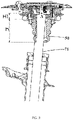
FIG. 1 is a schematic structural view of a strut assembly provided by an embodiment of the present disclosure; -
FIG. 2 is a schematic structural view of the strut assembly when the shock absorber is in a rising compression state; -
FIG. 3 is a schematic structural view of the strut assembly when the shock absorber is in an inclined compression state; -
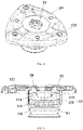
FIG. 4 is a schematic structural view of the upper support of the shock absorber; -
FIG. 5 is a cross-sectional view of the upper support of the shock absorber; -
FIG. 6 is a schematic structural view of the bearing; -
FIG. 7 is a cross-sectional view of the bearing; -
FIG. 8 is a schematic structural view of the first buffer device; -
FIG.9 is a cross-sectional view of the first buffer device; -
FIG. 10 is a schematic structural view of the buffer block; -
FIG. 11 is a schematic structural view of the shock absorber. - In the
figure: 10 - upper support of the shock absorber, 11- first through hole, 12- upper cover, 121- first boss, 13- first recess portion, 131- shock-absorbing rubber, 132- flange, 133- vertical portion, 134-connecting piece, 14-second recess portion, 141-clamping portion, 20-bearing, 21-second through hole, 22--first part, 221-second boss, 2211-first convex ring, 2212-second convex ring, 2213-reinforcing vertical rib, 2214-second convex rib, 23-second part, 24-third part, 241-barb hook, 242-horizontal hook, 30-first buffer device, 31-support frame, 311-bent portion, 32-first convex rib, 40-spring, 50-buffer block, 51-third through hole, 52-groove, 60-dust cover, 70- shock absorber, 71-piston rod of the shock absorber, 711-first rod portion, 722-second rod portion, 72-housing, 80-second buffer device, 90-vehicle body; - I-first channel, II-second channel, III-third channel;
- A-rotation center of the piston rod of the shock absorber;
- h-the height of the buffer block;
- H-the height difference between the lowest portion of the bearing and the lowest portion of the upper support of the shock absorber;
- H1-the distance between the rotation center and the highest point of the buffer block;
- L-the radial width difference between the lowest portion of the bearing and the lowest portion of the bearing on the shock absorber.
- The technical solutions in the embodiments of the present disclosure will be clearly and completely described below with reference to the accompanying drawings in the embodiments of the present disclosure. Obviously, the described embodiments are only some of the embodiments of the present disclosure, rather than all of the embodiments. Based on the embodiments of the present disclosure, all other embodiments obtained by those of ordinary skill in the art without creative work fall within the protection scope of the present disclosure.
- It should be noted that the terms "first", "second" and the like in the description, claims and drawings of the present disclosure are used to distinguish similar objects, and are not necessarily used to describe a relative importance or specific sequence. It is to be understood that the data so used may be interchanged under appropriate circumstances such that the embodiments of the invention described herein can be practiced in sequences other than those illustrated or described herein. In addition, the terms of direction or positional relationship indicated by the terms "middle", "upper", "lower", "inner", "outer" and the like are based on the directional or positional relationship shown in the drawings, which is only for convenience of description, rather than indicating or implying that the device or element must have a particular orientation, or be constructed and operate in a particular orientation, and therefore should not be understood as a limitation of the present disclosure. The terms "comprising" and "having", and any variations thereof, are intended to cover non-exclusive inclusion.
- Referring to
FIGS. 1 to 11 , an embodiment of the present disclosure provides a strut assembly, which includes ashock absorber 70, anupper support 10 of the shock absorber, abearing 20, aspring 40 and abuffer block 50. Theshock absorber 70, theupper support 10 of the shock absorber, thebearing 20, thespring 40 and thebuffer block 50 are coaxially arranged. - The
shock absorber 70 includes apiston rod 71, thepiston rod 71 of the shock absorber is coaxially arranged with theupper support 10 of the shock absorber, and theupper support 10 of the shock absorber is provided with a first through hole 11 (as shown inFIG. 4 ), thebearing 20 is provided with a second through hole 21 (as shown inFIG. 6 ), and a portion of theupper support 10 of the shock absorber is arranged in the second throughhole 21. Thebuffer block 50 is provided with a third through hole 51 (as shown inFIG. 10 ), one end of thepiston rod 71 of the shock absorber is located in the first throughhole 11, and the other end of thepiston rod 71 of the shock absorber passes through the third throughhole 51. - The
buffer block 50 is connected with theupper support 10 of the shock absorber, thespring 40 is sleeved outside thepiston rod 71 of the shock absorber, and thespring 40 is connected with thebearing 20. - As shown in
FIGS. 4 and 5 , in the embodiment of the present disclosure, theupper support 10 of the shock absorber includes anupper cover 12, afirst recess portion 13 with an upward opening and asecond recess portion 14 with a downward opening. Theupper cover 12, thefirst recess portion 13 and thesecond recess portion 14 are connected in sequence, the first throughhole 11 penetrates through theupper cover 12, thefirst recess portion 13 and thesecond recess portion 14, and thebuffer block 50 is connected with thesecond recess portion 14. - An outer diameter of the
upper cover 12 is larger than a diameter of the second throughhole 21. An outer diameter of thefirst recess portion 13 and an outer diameter of thesecond recess portion 14 are smaller than a diameter of the second throughhole 21 of thebearing 20, so that thefirst recess portion 13 is arranged in the second throughhole 21 of thebearing 20, thesecond recess portion 14 can partially protrude out from the second throughhole 21, and theupper cover 12 is blocked outside the second throughhole 21. - A bottom of the
first recess portion 13 is fixedly connected with a top of the second recess portion 14 (as shown inFIG. 5 ). The bottom of thefirst recess portion 13 is provided with a first opening, and the top of thesecond recess portion 14 is provided with a second opening. The first opening is matched with the second opening and both are larger than the size of thepiston rod 71 of the shock absorber, so that thepiston rod 71 of the shock absorber can pass therethrough. - The
first recess portion 13 is further provided with aflange 132, theflange 132 is used for fixed connection with theupper cover 12, the size of theflange 132 is smaller than the size of theupper cover 12. Avertical portion 133 is located between theflange 132 and the bottom of thefirst recess portion 13. - The
second recess portion 14 is provided with a clampingportion 141, thebuffer block 50 is provided with agroove 52, and the clampingportion 141 cooperates with thegroove 52 so that theupper support 10 of the shock absorber and thebuffer block 50 is connected. - As shown in
FIGS. 1 to 3 , the size of thesecond recess portion 14 is larger than that of an end portion of thebuffer block 50, so that the end portion of thebuffer block 50 is accommodated in thesecond recess portion 14. Therefore, a force F3 exerted on thebuffer block 50 reaches thevehicle body 90 sequentially through thesecond recess portion 13, thevertical portion 133 and theupper cover 12, that is, the transmission path of the force F3 exerted on thebuffer block 50 does not pass through thebearing 20. The transmission path of force F3 is shown as the third channel III inFIG. 1 . - The
upper cover 12 is provided with a plurality offirst bosses 121, and thefirst bosses 121 are provided with a plurality of mounting holes. As shown inFIG. 4 , thefirst bosses 121 are provided with three, and the threefirst bosses 121 are evenly distributed on a surface of theupper cover 12. Of course, thefirst bosses 121 may also be provided in other numbers. - It should be noted that since the
upper cover 12 is provided with thefirst boss 121, an upper surface of theupper cover 12 is not a horizontal plane, when theupper support 10 of the shock absorber is installed on thevehicle body 90, thefirst boss 121 contacts with the vehicle body in a small surface, which can avoid abnormal noise caused by collision between the upper support of the shock absorber and the vehicle body. Furthermore, thefirst boss 121 can be formed by stamping, which results low cost as compared with a method of arranging a vulcanized rubber layer for the contact between the upper support of the shock absorber and the vehicle body. - It should be noted that, in the embodiment of the present disclosure, the
flange 132 is also provided with an opening at a position corresponding to the mounting hole, so that the struct assembly provided in the embodiment of the present disclosure is assembled to the vehicle body (or frame) by fasteners (such as screws, etc.), the fasteners pass through the mounting hole of theupper cover 12 and the opening at theflange 132, which not only facilitates the realization of the fixed connection between theupper support 10 of the shock absorber and the vehicle body, and also beneficial to ensure the structural stability of theupper support 10 of the shock absorber. - The
first recess portion 13 is connected with theupper cover 12 to form a cavity, the cavity is provided with a dampingrubber 131 and a connectingpiece 134, and one end of thepiston rod 71 of the shock absorber passes through the dampingrubber 131 and the connectingpiece 134. -
FIG. 11 is a schematic structural view of theshock absorber 70, theshock absorber 70 includes thepiston rod 71 and ahousing 72, and thepiston rod 71 of the shock absorber includes afirst rod portion 711 and asecond rod portion 712. A diameter of thefirst rod portion 711 is smaller than a diameter of thesecond rod portion 712. - A diameter of the through hole of the connecting
piece 134 is larger than a diameter of thefirst rod portion 711 but smaller than a diameter of thesecond rod portion 712, so that the connectingpiece 134 can limit the upward stroke of thepiston rod 71 of the shock absorber, and make thepiston rod 71 of the shock absorber swing around a center of the connectingpiece 134 when it is subjected to a biasing force. Note that the center of the connectingpiece 134 is also a rotation center of thepiston rod 71 of the shock absorber as point A. Since thefirst boss 121 makes the upper surface of the upper cover be a non-planar surface, a distance H1 from the rotation center A to the top surface of thebuffer block 50 is reduced. - The connecting
piece 134 is provided between an upper part and a lower part of the shock-absorbingrubber 131. Therefore, the damping force F1 of theshock absorber 70 reaches thevehicle body 90 through the connectingpiece 134, the dampingrubber 131 and theupper cover 12 in sequence, that is, the transmission path of the damping force F1 of theshock absorber 70 also does not pass through thebearing 20. The transmission path of the force F1 is shown as the first channel I inFIG. 1 . - In the embodiment of the present disclosure, the
first recess portion 13 is provided with a bushing, the bushing is arranged coaxially with thefirst recess portion 13, and the size of the bushing is slightly smaller than that of thevertical portion 133 of thefirst recess portion 13, and the bushing is in clearance fit with thevertical portion 133. The shock-absorbingrubber 131 is connected to the bushing, an upper end of the shock-absorbingrubber 131 is in contact with theupper cover 12, and a lower end of the shock-absorbingrubber 131 is in contact with the bottom of thefirst recess portion 13. - A
first buffer device 30 is provided between the bearing 20 and thespring 40, and thefirst buffer device 30 is arranged coaxially with thebearing 20. Therefore, the force F2 exerted on thespring 40 reaches thevehicle body 90 through thefirst buffer device 30, thebearing 20, thefirst recess portion 13 of the upper support of the shock absorber and theupper cover 12 in sequence, and the transmission of the force F2 is shown as the second channel II inFIG. 1 . Thefirst buffer device 30 can protect thebearing 20, improve the service life of thebearing 20, and avoid abnormal noise caused by the collision between the bearing 20 and thespring 40. An upper surface of thefirst buffer device 30 is connected to thebearing 20, and a lower surface of thefirst buffer device 30 is connected to thespring 40. - As shown in
FIG. 8 and FIG. 9 , asupport frame 31 is provided inside thefirst buffer device 30, and thesupport frame 31 can improve the structural strength of thefirst buffer device 30. Thefirst buffer device 30 and thesupport frame 31 are both annular structures. Thesupport frame 31 includes a horizontal portion and abent portion 311. The horizontal portion and thebent portion 311 are integrated into one single piece. Thebent portion 311 is disposed at an inner ring edge of thesupport frame 31, thebent portion 311 has a smooth surface, and thebent portion 311 can prevent an end of thesupport frame 31 from piercing through thefirst buffer device 30, which is beneficial to improve the service life of thefirst buffer device 30 and avoid damage to thepiston rod 71 of the shock absorber disposed inside thefirst buffer device 30 after thesupport frame 31 pierces through the first buffer device. - A plurality of first
convex ribs 32 are arranged on an inner side wall of thefirst buffer device 30. The plurality of firstconvex ribs 32 are evenly distributed, and the firstconvex ribs 32 are used for interference connection with thebearing 20. - Preferably, the size of the
first buffer device 30 can make thefirst buffer device 30 cover a contact area between thespring 40 and thebearing 20. - As shown in
FIG. 6 and FIG. 7 , in the strut assembly provided in the embodiment of the present disclosure, thebearing 20 is in cylindrical shape, and thebearing 20 includes afirst part 22, asecond part 23 and athird part 24 connected in sequence. The second throughhole 21 penetrates through thefirst part 22, thesecond part 23 and thethird part 24. An upper surface of thefirst buffer device 30 contacts with a bottom surface of thefirst part 22, and the firstconvex rib 32 is in an interference fit with thesecond part 23, so that the firmness of the assembly of thefirst buffer device 30 can be improved. - An upper surface of the
first part 22 is provided with asecond boss 221, thebearing 20 is connected with theupper support 10 of the shock absorber through thesecond boss 221, and thesecond boss 221 is connected to theupper support 10 of the shock absorber in a small contact surface, which is beneficial to reduce or avoid the abnormal sound caused by the collision between the bearing 20 and theupper support 10 of the shock absorber. - Preferably, the
second boss 221 includes a firstconvex ring 2211 and a secondconvex ring 2212, an inner diameter of the firstconvex ring 2211 is larger than an inner diameter of the secondconvex ring 2212, the first convex ring and the second convex ring are concentric rings. - The
second boss 221 further includes a plurality of reinforcingvertical ribs 2213, the reinforcingvertical ribs 2213 connect the firstconvex ring 2211 with the secondconvex ring 2212, and the reinforcingvertical ribs 2213 are evenly distributed along the circumferential direction. - The first convex ring, the second convex ring and the reinforcing vertical ribs form a plurality of "H"-shaped supporting structures with strong supporting capability. The
bearing 20 is in contact with theflange 132 of the first recess portion of theupper support 10 of the shock absorber through the "H"-shaped support structure. Compared with the large-surface contact method adopted in the prior art, it can reduce the abnormal contact noise between the bearing 20 and theupper support 10 of the shock absorber. - A second
convex rib 2214 is provided from the reinforcingvertical rib 2213 toward the center of thebearing 20, the secondconvex rib 2214 is arranged at an inner side wall of the first part, and the secondconvex rib 2214 forms a line-to-surface contact with thepiston rod 71 of the shock absorber inserted into thebearing 20. Compared with the surface-to-surface contact method used in the prior art, it can reduce or even avoid the damage to the bearing caused by the collision between the shockabsorber piston rod 71 and thebearing 20, and further avoid abnormal noise caused by the collision, and improve the NVH (Noise, Vibration, Harshness, Noise, Vibration and Harshness) performance of the vehicle. - A hook is provided at an outer edge of a bottom of the
third part 24. - The strut assembly provided in the embodiment of the present disclosure further includes a
dust cover 60, and thedust cover 60 is sleeved outside thebuffer block 50. Specifically, one end of thedust cover 60 is connected to thebearing 20 through the hook, and the other end of thedust cover 60 is arranged to be connected with thehousing 72 of theshock absorber 70, so that thedust cover 60 can shield the exposed part of thepiston rod 71 of the shock absorber and thebuffer block 50, serves to prevent impurities such as dust, sediment and the like from entering the inside of the strut assembly. - As shown in
FIG. 7 , the hooks include barb hooks 241 andhorizontal hooks 242. Thebarb hook 241 form an included angle with the outer side wall of thebearing 20, and the included angle is an acute angle. The barb hooks 241 can increase the clamping force on thedust cover 60, so that thedust cover 60 is not easy to fall off, and thehorizontal hook 242 can facilitate the assembly and replacement of thedust cover 60. - Optionally, the barb hooks 241 and the
horizontal hooks 242 are symmetrically distributed around the outer wall of thebearing 20. - A plurality of the barb hooks 241 and the
horizontal hooks 242 can be provided. - That is, as shown in
FIG. 2 , an embodiment of the present disclosure provides a strut assembly, wherein the height of the lowest portion of theupper support 10 of the shock absorber is lower than the height of the lowest portion of thebearing 20, and a height difference between the lowest portion of thebearing 20 and the lowest portion of theupper support 10 of the shock absorber is H. An outer diameter of the lowest portion of theupper support 10 of the shock absorber is smaller than an outer diameter of the lowest portion of thebearing 20, and a radial width difference between the lowest portion of thebearing 20 and the lowest portion of theupper support 10 of the shock absorber is L. - When the vehicle passes through the undulating road surface and the wheels are at the upper limit of vertical motion, the
shock absorber 70 presses thebuffer block 50 upwardly. If thebuffer block 50 is compressed to the limit position (as shown inFIG. 2 ), thehousing 72 of the shock absorber can only touch the bottom of theupper support 10 of the shock absorber because there is a height difference H between the bearing 20 and theupper support 10 of the shock absorber. Therefore, under the limit state, thehousing 72 of the shock absorber can only touch theupper support 10 of the shock absorber, but cannot touch thebearing 20, and thebearing 20 will not be damaged under a strong impact, so that thebearing 20 is protected. - When the vehicle is cornering, the change in the direction of the wheel will exert a torque on the strut assembly, causing the
piston rod 71 of the shock absorber to change its angle about its rotation center A (as shown inFIG. 3 ). When thepiston rod 71 of the shock absorber rotates, if thebuffer block 50 is compressed and deformed to the limit position, due to the radial width difference L, thebuffer block 50 will not collide with thebearing 20 and cause damage to it. - Meanwhile, since the distance H1 from the rotation center A to the top surface of the
buffer block 50 is reduced, the swing range of thepiston rod 71 of the shock absorber is greatly restricted when it rotates, so that the amount of interference between thepiston rod 71 of the shock absorber and thebuffer block 50 is reduced, the abnormal noise is reduced and the hard damage to thebuffer block 50 is reduced as well. - The
spring 40 is a coil spring, and the side where thespring 40 meets thebearing 20 is provided with a horizontal portion (i.e., as shown inFIG. 1 , thespring 40 is in the same horizontal planar at a contact portion with the first buffer device 30) to avoid local contact between thespring 40 and thebearing 20, so that the force on thespring 40 can be evenly transmitted to thebearing 20 through thefirst buffer device 30, and thebearing 20 will not be broken due to uneven force. Accordingly, thebearing 20 is symmetrically arranged at the position contact with thefirst part 22, which can also reduce the difficulty of producing and manufacturing thebearing 20. - The strut assembly provided in the embodiment of the present disclosure further includes a spring support bracket, the spring support bracket is arranged at an outer side wall of the housing of the
shock absorber 70, and an end of thespring 40 away from thebearing 20 is connected to the spring support frame through asecond buffer device 80. - The strut assembly provided in the present disclosure can transmit the impact load of the road surface to the vehicle body through three channels, namely:
- The first channel I: the damping force F1 of the
shock absorber 70 reaches the vehicle body through the connectingpiece 134, the shock-absorbingrubber 131 and theupper cover 12 in sequence; - The second channel II: the force F2 exerted on the
spring 40 reaches thevehicle body 90 through thefirst buffer device 30, thebearing 20, thefirst recess portion 13 of the upper support of the shock absorber and theupper cover 12 in sequence; - The third channel III: the force F3 exerted on the
buffer block 50 reaches thevehicle body 90 through thesecond recess portion 13, thevertical portion 133 and theupper cover 12 in sequence; - The first channel I and the third channel III do not pass through the bearing, and the force F3 exerted on the buffer block is relatively large (about 43KN), so the bearing will not be damaged due to the excessive load, and the
bearing 20 does not need to be made of high-performance materials, which helps to reduce costs. - In the strut assembly provided in the embodiment of the present disclosure, there is a height difference H between the bearing 20 and the
upper support 10 of the shock absorber, so that thehousing 72 of the shock absorber only touches theupper support 10 of the shock absorber at the extreme position of the upward movement, but cannot touch thebearing 20, so that thebearing 20 will not be damaged under a strong impact, thus realizing the protection of thebearing 20. - Meanwhile, there is a radial width difference L between the lowest portion of the
bearing 20 and the lowest portion of theupper support 10 of the shock absorber. Therefore, when thebuffer block 50 is compressed to the limit position with the rotation of thepiston rod 71 of the shock absorber, thebuffer block 50 will not collide with thebearing 20 and cause damage to it. - The first boss is provided at the contact position between the
upper support 10 of the shock absorber and the vehicle body, and the first boss forms a small surface contact with the vehicle body, which can prevent the upper support of the shock absorber from colliding with the vehicle body and producing abnormal noise. Thefirst boss 121 can be formed by stamping, and the cost is low as compared with the method of the prior art by arranging a vulcanized rubber layer for the contact between the upper support of the shock absorber and the vehicle body. - The
first buffer device 30 is arranged between the bearing 20 and thespring 40. Thefirst buffer device 30 can protect thebearing 20, improve the service life of thebearing 20, and avoid the abnormal sound caused by the collision between the bearing 20 and thespring 40. - The
second boss 221 is provided at the contact position between the bearing and the upper support of the shock absorber, and the second boss forms a small surface contact with theupper support 10 of the shock absorber, which is beneficial to reduce or avoid the abnormal sound caused by the collision between the bearing 20 and theupper support 10 of the shock absorber. - The
first boss 121 reduces the distance H1 from the rotation center A to the top surface of thebuffer block 50, so that the swing amplitude of thepiston rod 71 of the shock absorber about the rotation center A is reduced, and the amount of interference between thepiston rod 71 of the shock absorber and the buffer blocks 50 is reduced, accordingly, the abnormal noise is reduced, and the hard damage to the buffer blocks 50 is reduced as well. - The load of the
spring 40 can be evenly distributed on thebearing 20, and thebearing 20 will not be broken due to uneven force. - Referring to
FIGS. 1 to 11 , an embodiment of the present disclosure provides a vehicle, which includes avehicle body 90, a wheel hub and the strut assembly described in Embodiment 1. The strut assembly is connected with thevehicle body 90 through thefirst boss 121 of theupper support 10 of the shock absorber, and the strut assembly is connected with the wheel hub through thepiston rod 71 of the shock absorber. - The above descriptions are only preferred embodiments of the present disclosure, and are not intended to limit the present disclosure. For those skilled in the art, it is obvious that the present disclosure is not limited to the details of the above-mentioned exemplary embodiments, and the present disclosure can be implemented in other specific forms without departing from the spirit or essential features of the present disclosure. Therefore, the embodiments are to be regarded in all respects as illustrative and not restrictive, and the scope of the invention is to be defined by the appended claims rather than the foregoing description. It is therefore intended to embrace all changes fallen within the meaning and scope of the equivalents in the scope of the claims of in the present disclosure. Any reference signs in the claims shall not be construed as limiting the involved claim.
Claims (10)
- A strut assembly, characterized by comprising a piston rod (71) of a shock absorber, an upper support (10) of the shock absorber, a bearing (20), a spring (40) and a buffer block (50), which are coaxially arranged;
the upper support (10) of the shock absorber being provided with a first through hole (11), the bearing (20) being provided with a second through hole (21), and a portion of the upper support (10) of the shock absorber being arranged in the second through hole (21), the buffer block (50) being provided with a third through hole (51), and one end of the piston rod (71) of the shock absorber being located in the first through hole (11), the other end of the piston rod (71) of the shock absorber passing through the third through hole (51), the buffer block (50) being connected with the upper support (10) of the shock absorber, the spring (40) being sleeved around the piston rod (71) of the shock absorber, and the spring (40) being connected with the bearing (20). - The strut assembly according to claim 1, wherein the upper support (10) of the shock absorber comprises an upper cover (12), a first recess portion (13) and a second recess portion (14) connected in sequence, the first through hole (11) penetrates the upper cover (12), the first recess portion (13) and the second recess portion (14), the buffer block (50) and the second recess portion (14) are connected, the upper cover (12) is blocked outside the second through hole (21), the first recess portion (13) is located in the second through hole (21), the second recess portion (14) can partially protrude out the second through hole (21).
- The strut assembly according to claim 2, wherein the second recess portion (14) is provided with a clamping portion (141), and the buffer block (50) is provided with a groove (52), the clamping portion (141) cooperates with the groove (52) to connect the upper support (10) of the shock absorber with the buffer block (50).
- The strut assembly according to claim 2, wherein a shock-absorbing rubber (131) and a connecting piece are further provided between the first recess portion (13) and the upper cover (12), the connecting piece is arranged on an outer circumference of the piston rod (71) of the shock absorber, and the connecting piece is located between an upper portion and a lower portion of the shock-absorbing rubber (131).
- The strut assembly according to claim 2, wherein the upper cover (12) is provided with a plurality of first bosses (121), and the first bosses (121) are provided with a plurality of mounting holes.
- The strut assembly according to claim 2, wherein a first buffer device (30) is arranged between the bearing (20) and the spring (40), and the first buffer device (30) is coaxially arranged with the bearing (20).
- The strut assembly according to claim 6, wherein a second boss (22) is provided on a side of the bearing (20) away from the first buffer device (30), the bearing (20) is connected with the first recess portion (13) of the upper support (10) of the shock absorber through the second boss (22).
- The strut assembly according to claim 1, wherein a height of the lowest portion of the upper support (10) of the shock absorber is lower than a height of the lowest portion of the bearing (20), an outer diameter of the lowest portion of the upper support (10) of the shock absorber is smaller than an outer diameter of the lowest portion of the bearing (20).
- The strut assembly according to claim 1, wherein the spring (40) is a coil spring, and a side of the spring (40) close to the bearing (20) is provided with a horizontal portion.
- A vehicle, characterized by comprising a vehicle body (90), a wheel hub and the strut assembly according to any one of claims 1 to 9, the strut assembly being connected with the vehicle body (90) through the first boss (121) of the upper support (10) of the shock absorber, and the strut assembly being connected with the wheel hub through the piston rod (71) of the shock absorber.
Applications Claiming Priority (1)
| Application Number | Priority Date | Filing Date | Title |
|---|---|---|---|
| PCT/CN2020/080021 WO2021184258A1 (en) | 2020-03-18 | 2020-03-18 | Strut assembly and vehicle applying same |
Publications (2)
| Publication Number | Publication Date |
|---|---|
| EP4122725A1 true EP4122725A1 (en) | 2023-01-25 |
| EP4122725A4 EP4122725A4 (en) | 2023-11-15 |
Family
ID=77769935
Family Applications (1)
| Application Number | Title | Priority Date | Filing Date |
|---|---|---|---|
| EP20925496.0A Pending EP4122725A4 (en) | 2020-03-18 | 2020-03-18 | PROP ASSEMBLY AND VEHICLE APPLYING THE SAME |
Country Status (6)
| Country | Link |
|---|---|
| US (1) | US12023975B2 (en) |
| EP (1) | EP4122725A4 (en) |
| JP (1) | JP7471439B2 (en) |
| KR (1) | KR102738162B1 (en) |
| CN (1) | CN115315364B (en) |
| WO (1) | WO2021184258A1 (en) |
Families Citing this family (4)
| Publication number | Priority date | Publication date | Assignee | Title |
|---|---|---|---|---|
| CN116638906A (en) * | 2023-05-30 | 2023-08-25 | 上海众力投资发展有限公司 | An upper support structure for a shock absorber |
| CN116951030A (en) * | 2023-07-27 | 2023-10-27 | 奇瑞新能源汽车股份有限公司 | Buffer block convenient to adjust, using method and sliding column comprising buffer block |
| CN119773656B (en) * | 2024-10-29 | 2025-11-04 | 比亚迪股份有限公司 | Support structure, distribution box, battery pack and electrical equipment |
| CN119058304B (en) * | 2024-11-01 | 2025-04-18 | 徐州美邦电动车科技有限公司 | A shock absorbing structure for electric tricycle |
Family Cites Families (22)
| Publication number | Priority date | Publication date | Assignee | Title |
|---|---|---|---|---|
| JPH08285002A (en) * | 1995-04-13 | 1996-11-01 | Bridgestone Corp | Strut mount structure |
| EP1072450A3 (en) | 1999-07-30 | 2001-11-07 | Firma Carl Freudenberg | Strut support bearing |
| DE10004945A1 (en) * | 2000-02-04 | 2001-08-09 | Volkswagen Ag | Shock absorber |
| FR2809675B1 (en) | 2000-05-30 | 2002-08-16 | Roulements Soc Nouvelle | SUSPENSION STOP DEVICE |
| JP4325198B2 (en) | 2003-01-21 | 2009-09-02 | 三菱自動車工業株式会社 | Synthetic resin sliding bearing and mounting structure of strut suspension using this sliding bearing |
| DE10308193B4 (en) | 2003-02-25 | 2005-02-03 | Zf Sachs Ag | Suspension strut with a stop buffer |
| JP2005054865A (en) * | 2003-08-01 | 2005-03-03 | Showa Corp | Bump rubber support structure of hydraulic shock absorber |
| FR2859513B1 (en) * | 2003-09-04 | 2006-07-21 | Zahnradfabrik Friedrichshafen | SUPPORT FOR AN OSCILLATION SHOCK ABSORBER |
| JP2005188591A (en) | 2003-12-25 | 2005-07-14 | Kayaba Ind Co Ltd | Spring seat |
| KR20060102209A (en) * | 2005-03-23 | 2006-09-27 | 주식회사 만도 | Strut Mount in Car Suspension |
| JP4841923B2 (en) | 2005-10-06 | 2011-12-21 | 株式会社ブリヂストン | Strut mount |
| DE102007024582A1 (en) * | 2007-05-25 | 2008-11-27 | Schaeffler Kg | Suspension strut bearing and strut |
| KR100962835B1 (en) | 2007-07-12 | 2010-06-09 | 현대자동차주식회사 | Suspension Strut Insulator Assembly |
| DE102007059800A1 (en) * | 2007-12-11 | 2009-06-18 | Zf Friedrichshafen Ag | Piston-cylinder unit with a piston rod protection |
| CN202510605U (en) * | 2012-03-29 | 2012-10-31 | 上海通用汽车有限公司 | Coil spring vibration isolator |
| US9193241B2 (en) | 2013-02-28 | 2015-11-24 | GM Global Technology Operations LLC | Systems and methods for damper having jounce shock |
| KR101646443B1 (en) * | 2015-01-30 | 2016-08-05 | 현대자동차주식회사 | Polymer Composite Strut Insulator and Suspension System thereby |
| CN106151345A (en) * | 2015-04-27 | 2016-11-23 | 株式会社万都 | The top installation structure of front damper |
| CN205022321U (en) | 2015-10-12 | 2016-02-10 | 力帆实业(集团)股份有限公司 | Buffer of shock absorber |
| CN206201892U (en) * | 2016-10-08 | 2017-05-31 | 浙江吉利控股集团有限公司 | A kind of upper shock absorber mount device |
| KR102635917B1 (en) * | 2018-08-29 | 2024-02-08 | 현대자동차주식회사 | Apparatus of adjusting vehicle height for suspension |
| FR3117991A1 (en) * | 2020-12-18 | 2022-06-24 | Renault S.A.S. | VEHICLE SUSPENSION STRUT |
-
2020
- 2020-03-18 JP JP2022554636A patent/JP7471439B2/en active Active
- 2020-03-18 EP EP20925496.0A patent/EP4122725A4/en active Pending
- 2020-03-18 WO PCT/CN2020/080021 patent/WO2021184258A1/en not_active Ceased
- 2020-03-18 CN CN202080097835.7A patent/CN115315364B/en active Active
- 2020-03-18 KR KR1020227033986A patent/KR102738162B1/en active Active
- 2020-03-18 US US17/912,060 patent/US12023975B2/en active Active
Also Published As
| Publication number | Publication date |
|---|---|
| CN115315364A (en) | 2022-11-08 |
| JP7471439B2 (en) | 2024-04-19 |
| CN115315364B (en) | 2025-12-23 |
| WO2021184258A1 (en) | 2021-09-23 |
| US20230122959A1 (en) | 2023-04-20 |
| US12023975B2 (en) | 2024-07-02 |
| JP2023517226A (en) | 2023-04-24 |
| KR20220148878A (en) | 2022-11-07 |
| KR102738162B1 (en) | 2024-12-05 |
| EP4122725A4 (en) | 2023-11-15 |
Similar Documents
| Publication | Publication Date | Title |
|---|---|---|
| US12023975B2 (en) | Strut assembly and vehicle applying same | |
| KR101096158B1 (en) | Compressor mounting structure | |
| CN109866568B (en) | Connecting device of rear shock absorber and automobile | |
| CN101445027A (en) | Lower spring seat mounting structure for vehicle suspension | |
| CN206503874U (en) | A kind of magnetic reprimand, spring integrated car damper | |
| US20220235844A1 (en) | Cover cap and insulator for shock absorber including the same | |
| CN209705139U (en) | Shock absorber upper support assembly and shock absorber components | |
| CN116412227B (en) | A linear dual-spring electromagnetic shock absorber for vehicles and a vehicle | |
| KR102647831B1 (en) | Shock absorber | |
| CN118107327A (en) | Suspension device and vehicle | |
| JP2002081503A (en) | Strut mount | |
| KR102563031B1 (en) | strut mount of suspension for vehicle | |
| CN214647411U (en) | An automobile swing arm with shock-absorbing bushing | |
| CN203892432U (en) | Shock absorber and car | |
| CN220168103U (en) | Damping device of automobile compressor and vehicle | |
| JP2006182136A (en) | Soundproof wheels for railway vehicles | |
| CN223720592U (en) | Buffer structure and suspension system | |
| CN224197531U (en) | Shock-resistant wheel steel ring | |
| CN222522809U (en) | Motorcycle shock absorbing device | |
| CN113135169B (en) | A vibration damping block for a vacuum pump and a vacuum pump assembly | |
| CN222910624U (en) | A shock absorber that is easy to install | |
| CN219692118U (en) | Shock absorber and vehicle with same | |
| CN202294124U (en) | Limiting block of vehicle suspension | |
| CN220227634U (en) | Valve seat structure of automobile shock absorber | |
| CN211924789U (en) | A new type of combined spring pad for shock absorber |
Legal Events
| Date | Code | Title | Description |
|---|---|---|---|
| STAA | Information on the status of an ep patent application or granted ep patent |
Free format text: STATUS: THE INTERNATIONAL PUBLICATION HAS BEEN MADE |
|
| PUAI | Public reference made under article 153(3) epc to a published international application that has entered the european phase |
Free format text: ORIGINAL CODE: 0009012 |
|
| STAA | Information on the status of an ep patent application or granted ep patent |
Free format text: STATUS: REQUEST FOR EXAMINATION WAS MADE |
|
| 17P | Request for examination filed |
Effective date: 20220907 |
|
| AK | Designated contracting states |
Kind code of ref document: A1 Designated state(s): AL AT BE BG CH CY CZ DE DK EE ES FI FR GB GR HR HU IE IS IT LI LT LU LV MC MK MT NL NO PL PT RO RS SE SI SK SM TR |
|
| DAV | Request for validation of the european patent (deleted) | ||
| DAX | Request for extension of the european patent (deleted) | ||
| A4 | Supplementary search report drawn up and despatched |
Effective date: 20231017 |
|
| RIC1 | Information provided on ipc code assigned before grant |
Ipc: B60G 15/06 20060101ALI20231011BHEP Ipc: F16F 1/12 20060101ALI20231011BHEP Ipc: F16F 9/54 20060101ALI20231011BHEP Ipc: B60G 13/06 20060101ALI20231011BHEP Ipc: B60G 15/07 20060101AFI20231011BHEP |
|
| STAA | Information on the status of an ep patent application or granted ep patent |
Free format text: STATUS: EXAMINATION IS IN PROGRESS |
|
| 17Q | First examination report despatched |
Effective date: 20250303 |