EP4122695A1 - Verfahren zum herstellen eines verstärkten kernverbundbauteils, insbesondere für luftfahrzeuge, kernverbundbauteil und luftfahrzeug - Google Patents
Verfahren zum herstellen eines verstärkten kernverbundbauteils, insbesondere für luftfahrzeuge, kernverbundbauteil und luftfahrzeug Download PDFInfo
- Publication number
- EP4122695A1 EP4122695A1 EP21186508.4A EP21186508A EP4122695A1 EP 4122695 A1 EP4122695 A1 EP 4122695A1 EP 21186508 A EP21186508 A EP 21186508A EP 4122695 A1 EP4122695 A1 EP 4122695A1
- Authority
- EP
- European Patent Office
- Prior art keywords
- core
- melt
- core structure
- core composite
- composite
- Prior art date
- Legal status (The legal status is an assumption and is not a legal conclusion. Google has not performed a legal analysis and makes no representation as to the accuracy of the status listed.)
- Granted
Links
Images




Classifications
-
- B—PERFORMING OPERATIONS; TRANSPORTING
- B29—WORKING OF PLASTICS; WORKING OF SUBSTANCES IN A PLASTIC STATE IN GENERAL
- B29C—SHAPING OR JOINING OF PLASTICS; SHAPING OF MATERIAL IN A PLASTIC STATE, NOT OTHERWISE PROVIDED FOR; AFTER-TREATMENT OF THE SHAPED PRODUCTS, e.g. REPAIRING
- B29C70/00—Shaping composites, i.e. plastics material comprising reinforcements, fillers or preformed parts, e.g. inserts
- B29C70/04—Shaping composites, i.e. plastics material comprising reinforcements, fillers or preformed parts, e.g. inserts comprising reinforcements only, e.g. self-reinforcing plastics
- B29C70/06—Fibrous reinforcements only
- B29C70/08—Fibrous reinforcements only comprising combinations of different forms of fibrous reinforcements incorporated in matrix material, forming one or more layers, and with or without non-reinforced layers
- B29C70/086—Fibrous reinforcements only comprising combinations of different forms of fibrous reinforcements incorporated in matrix material, forming one or more layers, and with or without non-reinforced layers and with one or more layers of pure plastics material, e.g. foam layers
-
- B—PERFORMING OPERATIONS; TRANSPORTING
- B29—WORKING OF PLASTICS; WORKING OF SUBSTANCES IN A PLASTIC STATE IN GENERAL
- B29C—SHAPING OR JOINING OF PLASTICS; SHAPING OF MATERIAL IN A PLASTIC STATE, NOT OTHERWISE PROVIDED FOR; AFTER-TREATMENT OF THE SHAPED PRODUCTS, e.g. REPAIRING
- B29C65/00—Joining or sealing of preformed parts, e.g. welding of plastics materials; Apparatus therefor
- B29C65/02—Joining or sealing of preformed parts, e.g. welding of plastics materials; Apparatus therefor by heating, with or without pressure
- B29C65/40—Applying molten plastics, e.g. hot melt
-
- B—PERFORMING OPERATIONS; TRANSPORTING
- B29—WORKING OF PLASTICS; WORKING OF SUBSTANCES IN A PLASTIC STATE IN GENERAL
- B29C—SHAPING OR JOINING OF PLASTICS; SHAPING OF MATERIAL IN A PLASTIC STATE, NOT OTHERWISE PROVIDED FOR; AFTER-TREATMENT OF THE SHAPED PRODUCTS, e.g. REPAIRING
- B29C65/00—Joining or sealing of preformed parts, e.g. welding of plastics materials; Apparatus therefor
- B29C65/48—Joining or sealing of preformed parts, e.g. welding of plastics materials; Apparatus therefor using adhesives, i.e. using supplementary joining material; solvent bonding
- B29C65/4805—Joining or sealing of preformed parts, e.g. welding of plastics materials; Apparatus therefor using adhesives, i.e. using supplementary joining material; solvent bonding characterised by the type of adhesives
- B29C65/481—Non-reactive adhesives, e.g. physically hardening adhesives
- B29C65/4815—Hot melt adhesives, e.g. thermoplastic adhesives
-
- B—PERFORMING OPERATIONS; TRANSPORTING
- B29—WORKING OF PLASTICS; WORKING OF SUBSTANCES IN A PLASTIC STATE IN GENERAL
- B29C—SHAPING OR JOINING OF PLASTICS; SHAPING OF MATERIAL IN A PLASTIC STATE, NOT OTHERWISE PROVIDED FOR; AFTER-TREATMENT OF THE SHAPED PRODUCTS, e.g. REPAIRING
- B29C65/00—Joining or sealing of preformed parts, e.g. welding of plastics materials; Apparatus therefor
- B29C65/48—Joining or sealing of preformed parts, e.g. welding of plastics materials; Apparatus therefor using adhesives, i.e. using supplementary joining material; solvent bonding
- B29C65/52—Joining or sealing of preformed parts, e.g. welding of plastics materials; Apparatus therefor using adhesives, i.e. using supplementary joining material; solvent bonding characterised by the way of applying the adhesive
- B29C65/524—Joining or sealing of preformed parts, e.g. welding of plastics materials; Apparatus therefor using adhesives, i.e. using supplementary joining material; solvent bonding characterised by the way of applying the adhesive by applying the adhesive from an outlet device in contact with, or almost in contact with, the surface of the part to be joined
-
- B—PERFORMING OPERATIONS; TRANSPORTING
- B29—WORKING OF PLASTICS; WORKING OF SUBSTANCES IN A PLASTIC STATE IN GENERAL
- B29C—SHAPING OR JOINING OF PLASTICS; SHAPING OF MATERIAL IN A PLASTIC STATE, NOT OTHERWISE PROVIDED FOR; AFTER-TREATMENT OF THE SHAPED PRODUCTS, e.g. REPAIRING
- B29C65/00—Joining or sealing of preformed parts, e.g. welding of plastics materials; Apparatus therefor
- B29C65/48—Joining or sealing of preformed parts, e.g. welding of plastics materials; Apparatus therefor using adhesives, i.e. using supplementary joining material; solvent bonding
- B29C65/52—Joining or sealing of preformed parts, e.g. welding of plastics materials; Apparatus therefor using adhesives, i.e. using supplementary joining material; solvent bonding characterised by the way of applying the adhesive
- B29C65/54—Joining or sealing of preformed parts, e.g. welding of plastics materials; Apparatus therefor using adhesives, i.e. using supplementary joining material; solvent bonding characterised by the way of applying the adhesive between pre-assembled parts
- B29C65/542—Joining or sealing of preformed parts, e.g. welding of plastics materials; Apparatus therefor using adhesives, i.e. using supplementary joining material; solvent bonding characterised by the way of applying the adhesive between pre-assembled parts by injection
-
- B—PERFORMING OPERATIONS; TRANSPORTING
- B29—WORKING OF PLASTICS; WORKING OF SUBSTANCES IN A PLASTIC STATE IN GENERAL
- B29C—SHAPING OR JOINING OF PLASTICS; SHAPING OF MATERIAL IN A PLASTIC STATE, NOT OTHERWISE PROVIDED FOR; AFTER-TREATMENT OF THE SHAPED PRODUCTS, e.g. REPAIRING
- B29C66/00—General aspects of processes or apparatus for joining preformed parts
- B29C66/01—General aspects dealing with the joint area or with the area to be joined
- B29C66/02—Preparation of the material, in the area to be joined, prior to joining or welding
- B29C66/022—Mechanical pre-treatments, e.g. reshaping
- B29C66/0224—Mechanical pre-treatments, e.g. reshaping with removal of material
- B29C66/02241—Cutting, e.g. by using waterjets, or sawing
-
- B—PERFORMING OPERATIONS; TRANSPORTING
- B29—WORKING OF PLASTICS; WORKING OF SUBSTANCES IN A PLASTIC STATE IN GENERAL
- B29C—SHAPING OR JOINING OF PLASTICS; SHAPING OF MATERIAL IN A PLASTIC STATE, NOT OTHERWISE PROVIDED FOR; AFTER-TREATMENT OF THE SHAPED PRODUCTS, e.g. REPAIRING
- B29C66/00—General aspects of processes or apparatus for joining preformed parts
- B29C66/01—General aspects dealing with the joint area or with the area to be joined
- B29C66/05—Particular design of joint configurations
- B29C66/10—Particular design of joint configurations particular design of the joint cross-sections
- B29C66/11—Joint cross-sections comprising a single joint-segment, i.e. one of the parts to be joined comprising a single joint-segment in the joint cross-section
- B29C66/116—Single bevelled joints, i.e. one of the parts to be joined being bevelled in the joint area
- B29C66/1162—Single bevel to bevel joints, e.g. mitre joints
-
- B—PERFORMING OPERATIONS; TRANSPORTING
- B29—WORKING OF PLASTICS; WORKING OF SUBSTANCES IN A PLASTIC STATE IN GENERAL
- B29C—SHAPING OR JOINING OF PLASTICS; SHAPING OF MATERIAL IN A PLASTIC STATE, NOT OTHERWISE PROVIDED FOR; AFTER-TREATMENT OF THE SHAPED PRODUCTS, e.g. REPAIRING
- B29C66/00—General aspects of processes or apparatus for joining preformed parts
- B29C66/01—General aspects dealing with the joint area or with the area to be joined
- B29C66/05—Particular design of joint configurations
- B29C66/10—Particular design of joint configurations particular design of the joint cross-sections
- B29C66/12—Joint cross-sections combining only two joint-segments; Tongue and groove joints; Tenon and mortise joints; Stepped joint cross-sections
- B29C66/122—Joint cross-sections combining only two joint-segments, i.e. one of the parts to be joined comprising only two joint-segments in the joint cross-section
- B29C66/1222—Joint cross-sections combining only two joint-segments, i.e. one of the parts to be joined comprising only two joint-segments in the joint cross-section comprising at least a lapped joint-segment
-
- B—PERFORMING OPERATIONS; TRANSPORTING
- B29—WORKING OF PLASTICS; WORKING OF SUBSTANCES IN A PLASTIC STATE IN GENERAL
- B29C—SHAPING OR JOINING OF PLASTICS; SHAPING OF MATERIAL IN A PLASTIC STATE, NOT OTHERWISE PROVIDED FOR; AFTER-TREATMENT OF THE SHAPED PRODUCTS, e.g. REPAIRING
- B29C66/00—General aspects of processes or apparatus for joining preformed parts
- B29C66/01—General aspects dealing with the joint area or with the area to be joined
- B29C66/05—Particular design of joint configurations
- B29C66/10—Particular design of joint configurations particular design of the joint cross-sections
- B29C66/12—Joint cross-sections combining only two joint-segments; Tongue and groove joints; Tenon and mortise joints; Stepped joint cross-sections
- B29C66/122—Joint cross-sections combining only two joint-segments, i.e. one of the parts to be joined comprising only two joint-segments in the joint cross-section
- B29C66/1224—Joint cross-sections combining only two joint-segments, i.e. one of the parts to be joined comprising only two joint-segments in the joint cross-section comprising at least a butt joint-segment
-
- B—PERFORMING OPERATIONS; TRANSPORTING
- B29—WORKING OF PLASTICS; WORKING OF SUBSTANCES IN A PLASTIC STATE IN GENERAL
- B29C—SHAPING OR JOINING OF PLASTICS; SHAPING OF MATERIAL IN A PLASTIC STATE, NOT OTHERWISE PROVIDED FOR; AFTER-TREATMENT OF THE SHAPED PRODUCTS, e.g. REPAIRING
- B29C66/00—General aspects of processes or apparatus for joining preformed parts
- B29C66/01—General aspects dealing with the joint area or with the area to be joined
- B29C66/05—Particular design of joint configurations
- B29C66/303—Particular design of joint configurations the joint involving an anchoring effect
- B29C66/3032—Particular design of joint configurations the joint involving an anchoring effect making use of protrusions or cavities belonging to at least one of the parts to be joined
- B29C66/30325—Particular design of joint configurations the joint involving an anchoring effect making use of protrusions or cavities belonging to at least one of the parts to be joined making use of cavities belonging to at least one of the parts to be joined
-
- B—PERFORMING OPERATIONS; TRANSPORTING
- B29—WORKING OF PLASTICS; WORKING OF SUBSTANCES IN A PLASTIC STATE IN GENERAL
- B29C—SHAPING OR JOINING OF PLASTICS; SHAPING OF MATERIAL IN A PLASTIC STATE, NOT OTHERWISE PROVIDED FOR; AFTER-TREATMENT OF THE SHAPED PRODUCTS, e.g. REPAIRING
- B29C66/00—General aspects of processes or apparatus for joining preformed parts
- B29C66/01—General aspects dealing with the joint area or with the area to be joined
- B29C66/05—Particular design of joint configurations
- B29C66/303—Particular design of joint configurations the joint involving an anchoring effect
- B29C66/3032—Particular design of joint configurations the joint involving an anchoring effect making use of protrusions or cavities belonging to at least one of the parts to be joined
- B29C66/30325—Particular design of joint configurations the joint involving an anchoring effect making use of protrusions or cavities belonging to at least one of the parts to be joined making use of cavities belonging to at least one of the parts to be joined
- B29C66/30326—Particular design of joint configurations the joint involving an anchoring effect making use of protrusions or cavities belonging to at least one of the parts to be joined making use of cavities belonging to at least one of the parts to be joined in the form of porosity
-
- B—PERFORMING OPERATIONS; TRANSPORTING
- B29—WORKING OF PLASTICS; WORKING OF SUBSTANCES IN A PLASTIC STATE IN GENERAL
- B29C—SHAPING OR JOINING OF PLASTICS; SHAPING OF MATERIAL IN A PLASTIC STATE, NOT OTHERWISE PROVIDED FOR; AFTER-TREATMENT OF THE SHAPED PRODUCTS, e.g. REPAIRING
- B29C66/00—General aspects of processes or apparatus for joining preformed parts
- B29C66/40—General aspects of joining substantially flat articles, e.g. plates, sheets or web-like materials; Making flat seams in tubular or hollow articles; Joining single elements to substantially flat surfaces
- B29C66/41—Joining substantially flat articles ; Making flat seams in tubular or hollow articles
- B29C66/43—Joining a relatively small portion of the surface of said articles
- B29C66/434—Joining substantially flat articles for forming corner connections, fork connections or cross connections
- B29C66/4342—Joining substantially flat articles for forming corner connections, e.g. for making V-shaped pieces
- B29C66/43421—Joining substantially flat articles for forming corner connections, e.g. for making V-shaped pieces with a right angle, e.g. for making L-shaped pieces
-
- B—PERFORMING OPERATIONS; TRANSPORTING
- B29—WORKING OF PLASTICS; WORKING OF SUBSTANCES IN A PLASTIC STATE IN GENERAL
- B29C—SHAPING OR JOINING OF PLASTICS; SHAPING OF MATERIAL IN A PLASTIC STATE, NOT OTHERWISE PROVIDED FOR; AFTER-TREATMENT OF THE SHAPED PRODUCTS, e.g. REPAIRING
- B29C66/00—General aspects of processes or apparatus for joining preformed parts
- B29C66/50—General aspects of joining tubular articles; General aspects of joining long products, i.e. bars or profiled elements; General aspects of joining single elements to tubular articles, hollow articles or bars; General aspects of joining several hollow-preforms to form hollow or tubular articles
- B29C66/51—Joining tubular articles, profiled elements or bars; Joining single elements to tubular articles, hollow articles or bars; Joining several hollow-preforms to form hollow or tubular articles
- B29C66/52—Joining tubular articles, bars or profiled elements
- B29C66/524—Joining profiled elements
-
- B—PERFORMING OPERATIONS; TRANSPORTING
- B29—WORKING OF PLASTICS; WORKING OF SUBSTANCES IN A PLASTIC STATE IN GENERAL
- B29C—SHAPING OR JOINING OF PLASTICS; SHAPING OF MATERIAL IN A PLASTIC STATE, NOT OTHERWISE PROVIDED FOR; AFTER-TREATMENT OF THE SHAPED PRODUCTS, e.g. REPAIRING
- B29C66/00—General aspects of processes or apparatus for joining preformed parts
- B29C66/50—General aspects of joining tubular articles; General aspects of joining long products, i.e. bars or profiled elements; General aspects of joining single elements to tubular articles, hollow articles or bars; General aspects of joining several hollow-preforms to form hollow or tubular articles
- B29C66/61—Joining from or joining on the inside
-
- B—PERFORMING OPERATIONS; TRANSPORTING
- B29—WORKING OF PLASTICS; WORKING OF SUBSTANCES IN A PLASTIC STATE IN GENERAL
- B29C—SHAPING OR JOINING OF PLASTICS; SHAPING OF MATERIAL IN A PLASTIC STATE, NOT OTHERWISE PROVIDED FOR; AFTER-TREATMENT OF THE SHAPED PRODUCTS, e.g. REPAIRING
- B29C66/00—General aspects of processes or apparatus for joining preformed parts
- B29C66/50—General aspects of joining tubular articles; General aspects of joining long products, i.e. bars or profiled elements; General aspects of joining single elements to tubular articles, hollow articles or bars; General aspects of joining several hollow-preforms to form hollow or tubular articles
- B29C66/63—Internally supporting the article during joining
- B29C66/636—Internally supporting the article during joining using a support which remains in the joined object
-
- B—PERFORMING OPERATIONS; TRANSPORTING
- B29—WORKING OF PLASTICS; WORKING OF SUBSTANCES IN A PLASTIC STATE IN GENERAL
- B29C—SHAPING OR JOINING OF PLASTICS; SHAPING OF MATERIAL IN A PLASTIC STATE, NOT OTHERWISE PROVIDED FOR; AFTER-TREATMENT OF THE SHAPED PRODUCTS, e.g. REPAIRING
- B29C66/00—General aspects of processes or apparatus for joining preformed parts
- B29C66/70—General aspects of processes or apparatus for joining preformed parts characterised by the composition, physical properties or the structure of the material of the parts to be joined; Joining with non-plastics material
- B29C66/72—General aspects of processes or apparatus for joining preformed parts characterised by the composition, physical properties or the structure of the material of the parts to be joined; Joining with non-plastics material characterised by the structure of the material of the parts to be joined
- B29C66/723—General aspects of processes or apparatus for joining preformed parts characterised by the composition, physical properties or the structure of the material of the parts to be joined; Joining with non-plastics material characterised by the structure of the material of the parts to be joined being multi-layered
-
- B—PERFORMING OPERATIONS; TRANSPORTING
- B29—WORKING OF PLASTICS; WORKING OF SUBSTANCES IN A PLASTIC STATE IN GENERAL
- B29C—SHAPING OR JOINING OF PLASTICS; SHAPING OF MATERIAL IN A PLASTIC STATE, NOT OTHERWISE PROVIDED FOR; AFTER-TREATMENT OF THE SHAPED PRODUCTS, e.g. REPAIRING
- B29C66/00—General aspects of processes or apparatus for joining preformed parts
- B29C66/70—General aspects of processes or apparatus for joining preformed parts characterised by the composition, physical properties or the structure of the material of the parts to be joined; Joining with non-plastics material
- B29C66/72—General aspects of processes or apparatus for joining preformed parts characterised by the composition, physical properties or the structure of the material of the parts to be joined; Joining with non-plastics material characterised by the structure of the material of the parts to be joined
- B29C66/725—General aspects of processes or apparatus for joining preformed parts characterised by the composition, physical properties or the structure of the material of the parts to be joined; Joining with non-plastics material characterised by the structure of the material of the parts to be joined being hollow-walled or honeycombs
- B29C66/7252—General aspects of processes or apparatus for joining preformed parts characterised by the composition, physical properties or the structure of the material of the parts to be joined; Joining with non-plastics material characterised by the structure of the material of the parts to be joined being hollow-walled or honeycombs hollow-walled
-
- B—PERFORMING OPERATIONS; TRANSPORTING
- B29—WORKING OF PLASTICS; WORKING OF SUBSTANCES IN A PLASTIC STATE IN GENERAL
- B29C—SHAPING OR JOINING OF PLASTICS; SHAPING OF MATERIAL IN A PLASTIC STATE, NOT OTHERWISE PROVIDED FOR; AFTER-TREATMENT OF THE SHAPED PRODUCTS, e.g. REPAIRING
- B29C66/00—General aspects of processes or apparatus for joining preformed parts
- B29C66/70—General aspects of processes or apparatus for joining preformed parts characterised by the composition, physical properties or the structure of the material of the parts to be joined; Joining with non-plastics material
- B29C66/72—General aspects of processes or apparatus for joining preformed parts characterised by the composition, physical properties or the structure of the material of the parts to be joined; Joining with non-plastics material characterised by the structure of the material of the parts to be joined
- B29C66/725—General aspects of processes or apparatus for joining preformed parts characterised by the composition, physical properties or the structure of the material of the parts to be joined; Joining with non-plastics material characterised by the structure of the material of the parts to be joined being hollow-walled or honeycombs
- B29C66/7252—General aspects of processes or apparatus for joining preformed parts characterised by the composition, physical properties or the structure of the material of the parts to be joined; Joining with non-plastics material characterised by the structure of the material of the parts to be joined being hollow-walled or honeycombs hollow-walled
- B29C66/72525—General aspects of processes or apparatus for joining preformed parts characterised by the composition, physical properties or the structure of the material of the parts to be joined; Joining with non-plastics material characterised by the structure of the material of the parts to be joined being hollow-walled or honeycombs hollow-walled comprising honeycomb cores
-
- B—PERFORMING OPERATIONS; TRANSPORTING
- B29—WORKING OF PLASTICS; WORKING OF SUBSTANCES IN A PLASTIC STATE IN GENERAL
- B29C—SHAPING OR JOINING OF PLASTICS; SHAPING OF MATERIAL IN A PLASTIC STATE, NOT OTHERWISE PROVIDED FOR; AFTER-TREATMENT OF THE SHAPED PRODUCTS, e.g. REPAIRING
- B29C66/00—General aspects of processes or apparatus for joining preformed parts
- B29C66/70—General aspects of processes or apparatus for joining preformed parts characterised by the composition, physical properties or the structure of the material of the parts to be joined; Joining with non-plastics material
- B29C66/72—General aspects of processes or apparatus for joining preformed parts characterised by the composition, physical properties or the structure of the material of the parts to be joined; Joining with non-plastics material characterised by the structure of the material of the parts to be joined
- B29C66/727—General aspects of processes or apparatus for joining preformed parts characterised by the composition, physical properties or the structure of the material of the parts to be joined; Joining with non-plastics material characterised by the structure of the material of the parts to be joined being porous, e.g. foam
-
- B—PERFORMING OPERATIONS; TRANSPORTING
- B29—WORKING OF PLASTICS; WORKING OF SUBSTANCES IN A PLASTIC STATE IN GENERAL
- B29C—SHAPING OR JOINING OF PLASTICS; SHAPING OF MATERIAL IN A PLASTIC STATE, NOT OTHERWISE PROVIDED FOR; AFTER-TREATMENT OF THE SHAPED PRODUCTS, e.g. REPAIRING
- B29C66/00—General aspects of processes or apparatus for joining preformed parts
- B29C66/70—General aspects of processes or apparatus for joining preformed parts characterised by the composition, physical properties or the structure of the material of the parts to be joined; Joining with non-plastics material
- B29C66/73—General aspects of processes or apparatus for joining preformed parts characterised by the composition, physical properties or the structure of the material of the parts to be joined; Joining with non-plastics material characterised by the intensive physical properties of the material of the parts to be joined, by the optical properties of the material of the parts to be joined, by the extensive physical properties of the parts to be joined, by the state of the material of the parts to be joined or by the material of the parts to be joined being a thermoplastic or a thermoset
- B29C66/739—General aspects of processes or apparatus for joining preformed parts characterised by the composition, physical properties or the structure of the material of the parts to be joined; Joining with non-plastics material characterised by the intensive physical properties of the material of the parts to be joined, by the optical properties of the material of the parts to be joined, by the extensive physical properties of the parts to be joined, by the state of the material of the parts to be joined or by the material of the parts to be joined being a thermoplastic or a thermoset characterised by the material of the parts to be joined being a thermoplastic or a thermoset
- B29C66/7392—General aspects of processes or apparatus for joining preformed parts characterised by the composition, physical properties or the structure of the material of the parts to be joined; Joining with non-plastics material characterised by the intensive physical properties of the material of the parts to be joined, by the optical properties of the material of the parts to be joined, by the extensive physical properties of the parts to be joined, by the state of the material of the parts to be joined or by the material of the parts to be joined being a thermoplastic or a thermoset characterised by the material of the parts to be joined being a thermoplastic or a thermoset characterised by the material of at least one of the parts being a thermoplastic
- B29C66/73921—General aspects of processes or apparatus for joining preformed parts characterised by the composition, physical properties or the structure of the material of the parts to be joined; Joining with non-plastics material characterised by the intensive physical properties of the material of the parts to be joined, by the optical properties of the material of the parts to be joined, by the extensive physical properties of the parts to be joined, by the state of the material of the parts to be joined or by the material of the parts to be joined being a thermoplastic or a thermoset characterised by the material of the parts to be joined being a thermoplastic or a thermoset characterised by the material of at least one of the parts being a thermoplastic characterised by the materials of both parts being thermoplastics
-
- B—PERFORMING OPERATIONS; TRANSPORTING
- B29—WORKING OF PLASTICS; WORKING OF SUBSTANCES IN A PLASTIC STATE IN GENERAL
- B29C—SHAPING OR JOINING OF PLASTICS; SHAPING OF MATERIAL IN A PLASTIC STATE, NOT OTHERWISE PROVIDED FOR; AFTER-TREATMENT OF THE SHAPED PRODUCTS, e.g. REPAIRING
- B29C70/00—Shaping composites, i.e. plastics material comprising reinforcements, fillers or preformed parts, e.g. inserts
- B29C70/04—Shaping composites, i.e. plastics material comprising reinforcements, fillers or preformed parts, e.g. inserts comprising reinforcements only, e.g. self-reinforcing plastics
- B29C70/28—Shaping operations therefor
- B29C70/54—Component parts, details or accessories; Auxiliary operations, e.g. feeding or storage of prepregs or SMC after impregnation or during ageing
- B29C70/545—Perforating, cutting or machining during or after moulding
-
- B—PERFORMING OPERATIONS; TRANSPORTING
- B29—WORKING OF PLASTICS; WORKING OF SUBSTANCES IN A PLASTIC STATE IN GENERAL
- B29C—SHAPING OR JOINING OF PLASTICS; SHAPING OF MATERIAL IN A PLASTIC STATE, NOT OTHERWISE PROVIDED FOR; AFTER-TREATMENT OF THE SHAPED PRODUCTS, e.g. REPAIRING
- B29C70/00—Shaping composites, i.e. plastics material comprising reinforcements, fillers or preformed parts, e.g. inserts
- B29C70/04—Shaping composites, i.e. plastics material comprising reinforcements, fillers or preformed parts, e.g. inserts comprising reinforcements only, e.g. self-reinforcing plastics
- B29C70/28—Shaping operations therefor
- B29C70/54—Component parts, details or accessories; Auxiliary operations, e.g. feeding or storage of prepregs or SMC after impregnation or during ageing
- B29C70/546—Measures for feeding or distributing the matrix material in the reinforcing structure
-
- B—PERFORMING OPERATIONS; TRANSPORTING
- B29—WORKING OF PLASTICS; WORKING OF SUBSTANCES IN A PLASTIC STATE IN GENERAL
- B29C—SHAPING OR JOINING OF PLASTICS; SHAPING OF MATERIAL IN A PLASTIC STATE, NOT OTHERWISE PROVIDED FOR; AFTER-TREATMENT OF THE SHAPED PRODUCTS, e.g. REPAIRING
- B29C70/00—Shaping composites, i.e. plastics material comprising reinforcements, fillers or preformed parts, e.g. inserts
- B29C70/04—Shaping composites, i.e. plastics material comprising reinforcements, fillers or preformed parts, e.g. inserts comprising reinforcements only, e.g. self-reinforcing plastics
- B29C70/28—Shaping operations therefor
- B29C70/54—Component parts, details or accessories; Auxiliary operations, e.g. feeding or storage of prepregs or SMC after impregnation or during ageing
- B29C70/546—Measures for feeding or distributing the matrix material in the reinforcing structure
- B29C70/547—Measures for feeding or distributing the matrix material in the reinforcing structure using channels or porous distribution layers incorporated in or associated with the product
-
- B—PERFORMING OPERATIONS; TRANSPORTING
- B29—WORKING OF PLASTICS; WORKING OF SUBSTANCES IN A PLASTIC STATE IN GENERAL
- B29C—SHAPING OR JOINING OF PLASTICS; SHAPING OF MATERIAL IN A PLASTIC STATE, NOT OTHERWISE PROVIDED FOR; AFTER-TREATMENT OF THE SHAPED PRODUCTS, e.g. REPAIRING
- B29C70/00—Shaping composites, i.e. plastics material comprising reinforcements, fillers or preformed parts, e.g. inserts
- B29C70/68—Shaping composites, i.e. plastics material comprising reinforcements, fillers or preformed parts, e.g. inserts by incorporating or moulding on preformed parts, e.g. inserts or layers, e.g. foam blocks
- B29C70/74—Moulding material on a relatively small portion of the preformed part, e.g. outsert moulding
- B29C70/745—Filling cavities in the preformed part
-
- B—PERFORMING OPERATIONS; TRANSPORTING
- B29—WORKING OF PLASTICS; WORKING OF SUBSTANCES IN A PLASTIC STATE IN GENERAL
- B29C—SHAPING OR JOINING OF PLASTICS; SHAPING OF MATERIAL IN A PLASTIC STATE, NOT OTHERWISE PROVIDED FOR; AFTER-TREATMENT OF THE SHAPED PRODUCTS, e.g. REPAIRING
- B29C70/00—Shaping composites, i.e. plastics material comprising reinforcements, fillers or preformed parts, e.g. inserts
- B29C70/68—Shaping composites, i.e. plastics material comprising reinforcements, fillers or preformed parts, e.g. inserts by incorporating or moulding on preformed parts, e.g. inserts or layers, e.g. foam blocks
- B29C70/74—Moulding material on a relatively small portion of the preformed part, e.g. outsert moulding
- B29C70/76—Moulding on edges or extremities of the preformed part
-
- B—PERFORMING OPERATIONS; TRANSPORTING
- B29—WORKING OF PLASTICS; WORKING OF SUBSTANCES IN A PLASTIC STATE IN GENERAL
- B29C—SHAPING OR JOINING OF PLASTICS; SHAPING OF MATERIAL IN A PLASTIC STATE, NOT OTHERWISE PROVIDED FOR; AFTER-TREATMENT OF THE SHAPED PRODUCTS, e.g. REPAIRING
- B29C70/00—Shaping composites, i.e. plastics material comprising reinforcements, fillers or preformed parts, e.g. inserts
- B29C70/68—Shaping composites, i.e. plastics material comprising reinforcements, fillers or preformed parts, e.g. inserts by incorporating or moulding on preformed parts, e.g. inserts or layers, e.g. foam blocks
- B29C70/84—Shaping composites, i.e. plastics material comprising reinforcements, fillers or preformed parts, e.g. inserts by incorporating or moulding on preformed parts, e.g. inserts or layers, e.g. foam blocks by moulding material on preformed parts to be joined
- B29C70/845—Shaping composites, i.e. plastics material comprising reinforcements, fillers or preformed parts, e.g. inserts by incorporating or moulding on preformed parts, e.g. inserts or layers, e.g. foam blocks by moulding material on preformed parts to be joined by moulding material on a relative small portion of the preformed parts
-
- B—PERFORMING OPERATIONS; TRANSPORTING
- B32—LAYERED PRODUCTS
- B32B—LAYERED PRODUCTS, i.e. PRODUCTS BUILT-UP OF STRATA OF FLAT OR NON-FLAT, e.g. CELLULAR OR HONEYCOMB, FORM
- B32B3/00—Layered products comprising a layer with external or internal discontinuities or unevennesses, or a layer of non-planar shape; Layered products comprising a layer having particular features of form
- B32B3/10—Layered products comprising a layer with external or internal discontinuities or unevennesses, or a layer of non-planar shape; Layered products comprising a layer having particular features of form characterised by a discontinuous layer, i.e. formed of separate pieces of material
- B32B3/12—Layered products comprising a layer with external or internal discontinuities or unevennesses, or a layer of non-planar shape; Layered products comprising a layer having particular features of form characterised by a discontinuous layer, i.e. formed of separate pieces of material characterised by a layer of regularly- arranged cells, e.g. a honeycomb structure
-
- B—PERFORMING OPERATIONS; TRANSPORTING
- B32—LAYERED PRODUCTS
- B32B—LAYERED PRODUCTS, i.e. PRODUCTS BUILT-UP OF STRATA OF FLAT OR NON-FLAT, e.g. CELLULAR OR HONEYCOMB, FORM
- B32B5/00—Layered products characterised by the non- homogeneity or physical structure, i.e. comprising a fibrous, filamentary, particulate or foam layer; Layered products characterised by having a layer differing constitutionally or physically in different parts
- B32B5/18—Layered products characterised by the non- homogeneity or physical structure, i.e. comprising a fibrous, filamentary, particulate or foam layer; Layered products characterised by having a layer differing constitutionally or physically in different parts characterised by features of a layer of foamed material
-
- B—PERFORMING OPERATIONS; TRANSPORTING
- B29—WORKING OF PLASTICS; WORKING OF SUBSTANCES IN A PLASTIC STATE IN GENERAL
- B29C—SHAPING OR JOINING OF PLASTICS; SHAPING OF MATERIAL IN A PLASTIC STATE, NOT OTHERWISE PROVIDED FOR; AFTER-TREATMENT OF THE SHAPED PRODUCTS, e.g. REPAIRING
- B29C2793/00—Shaping techniques involving a cutting or machining operation
- B29C2793/0081—Shaping techniques involving a cutting or machining operation before shaping
-
- B—PERFORMING OPERATIONS; TRANSPORTING
- B29—WORKING OF PLASTICS; WORKING OF SUBSTANCES IN A PLASTIC STATE IN GENERAL
- B29C—SHAPING OR JOINING OF PLASTICS; SHAPING OF MATERIAL IN A PLASTIC STATE, NOT OTHERWISE PROVIDED FOR; AFTER-TREATMENT OF THE SHAPED PRODUCTS, e.g. REPAIRING
- B29C2793/00—Shaping techniques involving a cutting or machining operation
- B29C2793/009—Shaping techniques involving a cutting or machining operation after shaping
-
- B—PERFORMING OPERATIONS; TRANSPORTING
- B29—WORKING OF PLASTICS; WORKING OF SUBSTANCES IN A PLASTIC STATE IN GENERAL
- B29L—INDEXING SCHEME ASSOCIATED WITH SUBCLASS B29C, RELATING TO PARTICULAR ARTICLES
- B29L2031/00—Other particular articles
- B29L2031/30—Vehicles, e.g. ships or aircraft, or body parts thereof
- B29L2031/3005—Body finishings
- B29L2031/3017—Floor coverings
-
- B—PERFORMING OPERATIONS; TRANSPORTING
- B29—WORKING OF PLASTICS; WORKING OF SUBSTANCES IN A PLASTIC STATE IN GENERAL
- B29L—INDEXING SCHEME ASSOCIATED WITH SUBCLASS B29C, RELATING TO PARTICULAR ARTICLES
- B29L2031/00—Other particular articles
- B29L2031/30—Vehicles, e.g. ships or aircraft, or body parts thereof
- B29L2031/3076—Aircrafts
-
- B—PERFORMING OPERATIONS; TRANSPORTING
- B32—LAYERED PRODUCTS
- B32B—LAYERED PRODUCTS, i.e. PRODUCTS BUILT-UP OF STRATA OF FLAT OR NON-FLAT, e.g. CELLULAR OR HONEYCOMB, FORM
- B32B2260/00—Layered product comprising an impregnated, embedded, or bonded layer wherein the layer comprises an impregnation, embedding, or binder material
- B32B2260/02—Composition of the impregnated, bonded or embedded layer
-
- B—PERFORMING OPERATIONS; TRANSPORTING
- B32—LAYERED PRODUCTS
- B32B—LAYERED PRODUCTS, i.e. PRODUCTS BUILT-UP OF STRATA OF FLAT OR NON-FLAT, e.g. CELLULAR OR HONEYCOMB, FORM
- B32B2260/00—Layered product comprising an impregnated, embedded, or bonded layer wherein the layer comprises an impregnation, embedding, or binder material
- B32B2260/04—Impregnation, embedding, or binder material
- B32B2260/046—Synthetic resin
-
- Y—GENERAL TAGGING OF NEW TECHNOLOGICAL DEVELOPMENTS; GENERAL TAGGING OF CROSS-SECTIONAL TECHNOLOGIES SPANNING OVER SEVERAL SECTIONS OF THE IPC; TECHNICAL SUBJECTS COVERED BY FORMER USPC CROSS-REFERENCE ART COLLECTIONS [XRACs] AND DIGESTS
- Y02—TECHNOLOGIES OR APPLICATIONS FOR MITIGATION OR ADAPTATION AGAINST CLIMATE CHANGE
- Y02T—CLIMATE CHANGE MITIGATION TECHNOLOGIES RELATED TO TRANSPORTATION
- Y02T50/00—Aeronautics or air transport
- Y02T50/40—Weight reduction
Definitions
- the invention relates to a method for producing a reinforced core composite component, in particular for aircraft. Furthermore, the invention relates to a core composite component and an aircraft.
- core composites consist of a core structure of relatively great height or thickness sandwiched between two thin skin layers. If areas are identified in these composites that are exposed to increased stress, this area is locally reinforced. This is done either through the use of core structures or components with a higher density or through the introduction of filling compounds, for example.
- a material with increased viscosity can be introduced locally into open cell structures, which completely fills the volume between the two cover layers.
- the mass is introduced before the application of the cover layers or cover skins and is cured with the skins or cover layers.
- This method can be used on the surface, but also in the area of subsequent cut edges. If you cut in the area of the filled cells, the border or edge is stabilized at the same time.
- This method is used, for example, on floor panels in the cabin area of aircraft to stabilize the edges against damage caused by rolling loads, e.g. from food trolleys.
- the plugs or stoppers are used for connection and power transmission between the plate and the floor structure.
- honeycomb composites are achieved according to the prior art by filling the honeycomb cells or by inserting plugs.
- the latter are also conceivable with foams.
- Due to the closed porosity the introduction of filling compounds is only possible after the prior creation of free volume by mechanical discharge. Furthermore, the methods can only be used before the cover skins are applied. It is therefore not possible to subsequently adapt generic plates using these methods.
- the invention has set itself the task of reducing cycle times in the production of core composite components, increasing flexibility and enabling specific or customer-specific differentiation as late as possible. Furthermore, the number of parts to be kept in stock should be reduced and the degree of automation and the output or the production rate should be increased.
- the invention creates a method for producing a reinforced core composite component according to patent claim 1.
- the invention makes it possible, among other things, to introduce filling compounds even when the porosity of the core structure is closed.
- a foam-based core composite is subsequently provided with local connections and reinforcements.
- the core structure is formed as a foam structure such as foam.
- the melt is preferably introduced under pressure.
- the pressure when introducing the thermoplastic melt is advantageously dimensioned in such a way that it displaces the foam structure in the partial area of the core structure.
- the temperature and the viscosity of the melt are also control parameters when carrying out the method.
- the core structure can also be designed as a honeycomb structure.
- part of the core structure can be removed in order to introduce the melt there.
- the pressure when introducing the melt is preferably reduced in such a way that further advancement of the melt within the core structure is stopped by its incipient cooling and solidification at the front and at the same time shrinkage of the volume of the melt within the core structure is prevented
- At least one opening for introducing the melt into the core structure is preferably made in at least one of the cover layers, the opening being formed, for example, as a bore or a gap and advantageously extending at least partially into or through the core structure.
- the gap can be formed as a groove, for example.
- the opening can be closed thermoplastically by the melt after it has been introduced.
- the opening is produced by drilling or milling in order to form a gap or milling gap, for example.
- a pressing element When introducing the melt, a pressing element preferably presses against the top layer in the region of the opening.
- the heated thermoplastic melt is simultaneously pressed into the gap that is being formed.
- the composite core component is preferably cut in the area of the gap, for example to form an edge reinforcement in the area of the core structure.
- a further composite core element is preferably provided for attachment to the first composite core component, the two composite core elements being positioned in such a way that their core structures are spaced apart from one another and form a joining gap.
- step (b) the heated thermoplastic melt is advantageously pressed into the joint gap in order to press it into at least a partial area of the respective core structure of both core composite elements.
- the core composite element provided is preferably cut from a core composite panel.
- the heated thermoplastic melt is advantageously injected continuously and/or circumferentially along the contour of the composite core element into the core structure in order to form an edge reinforcement.
- Two composite core components produced using the method are preferably connected to one another in the area of their edge reinforcements by thermoplastic welding.
- a protrusion of a load-bearing member is placed in the aperture, compressed, for example, under the action of pressure and temperature within the aperture, and then the heated thermoplastic melt is injected into the aperture with the protrusion therein to thermoplastically bond the core composite to the to connect load-bearing element.
- two or more core composites are spacedly connected to at least one protrusion of the load-bearing member, respectively, to form a reinforced member with the load-bearing member.
- a plurality of openings are preferably formed in the core structure in such a way that they form load paths of a bionic structure after the thermoplastic melt has been introduced and cooled.
- a workpiece that is formed by the core composite element is machined with the method described here.
- the invention creates a core composite component, comprising a core structure that is arranged between relatively thin cover layers, wherein the core structure is designed as a foam structure and/or honeycomb structure, and wherein a thermoplastic melt solidified in the core structure is used in a partial region of the core structure local reinforcement is arranged.
- the core composite component is preferably produced using the method according to the invention.
- the core composite component is a luggage compartment or overhead stowage compartment or a part thereof.
- the invention creates an aircraft which comprises a composite core component which is produced using the method according to the invention and/or comprises a composite core component according to the invention.
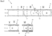
- figure 1 shows the process flow or the steps in the production of a core composite component 10 in different chronologically successive phases I to IV as a sectional view. The different phases are separated from each other in the figure by dashed lines for the sake of clarity.
- a core composite element 11 in the form of a foam-based core composite is subsequently provided with local connections and reinforcements.
- the core composite element 11 is first provided. It comprises a core structure 12 which is arranged between two relatively thin cover layers 13,14.
- the core structure 12 is made of a plastic, for example, and is designed as a foam structure in the form of a foam.
- the core structure 12 with the cover layers 13, 14 forms an undisturbed, finished foam core composite.
- an opening 15 in the form of a bore 16 is made in the top cover layer 13, i. H. into a cover layer side, in this case in the upper cover layer 13.
- the bore 16, which is designed as a hole, extends through the cover layer 13 and in this example through the entire core structure 12 to the opposite cover layer side, which extends through the lower cover layer 14 is formed.
- the bore 16 does not necessarily have to extend through the entire core structure 12 to the opposite side 14 of the cover layer. Depending on the depth of the hole, however, the flow profile will change in the subsequent process step.
- thermoplastic melt 17 is now introduced into the core structure 12 or into a partial area thereof, as indicated by the arrow E.
- An injection nozzle 18 is placed on the bore 16 for this purpose.
- the thermoplastic melt or thermoplastic melt 17, which can also be a thermoplastic hot-melt adhesive, for example, is now pressed through the nozzle 18 with a defined pressure into the foam composite or foam core composite and enters the core structure 12.
- the melt 17 By suitably matching the temperature of the melt 17 with the properties of the foam that forms the core structure 12, the latter is caused to collapse locally. Due to the pressure of the nozzle 18, the melt 17 progressively displaces the foam or the core structure 12 as it is pressed in and, after it has cooled down, will replace it with a thermoplastic or fully thermoplastic plug 19, which is formed by the solidified thermoplastic material
- the plug 19 and the foam 12 optimally connect or stick together at the front 20 of the melt during the process. This process is regulated via the pressure when pressing in the melt 17 in order to achieve an optimal connection or adhesion.
- the pressure or injection pressure is reduced to a holding pressure, as a result of which further advancement of the front 20 of the melt 17 is stopped and at the same time shrinkage of the melt 17 within the core structure 12 is prevented .
- the process pressure increases with the duration of the injection, since the melt 17 at the front 20 is already beginning to cool down.
- the temperature of the melt 17 and its viscosity are further control factors when injecting the melt 17. The necessary adjustments are made such that the melt 17 displaces the foam, which forms the core structure 12, but does not cause an uncontrolled collapse.
- a hold-down device In order to prevent the cover skins 13 or 14 of the composite core element 11 from being detached, it is also possible in the area of the injection, i. H. in the vicinity of the injection nozzle 18, a hold-down device, not shown in the figure, can be provided if this is necessary.
- the hold-down device presses the workpiece or the composite core element 11 against a support surface, similar to the sewing foot of a sewing machine.
- the melt 17 or the workpiece, which is now formed by the core composite element 11 filled with the solidified thermoplastic material has completely cooled down, it can be processed locally and in particular drilled and countersunk, as shown in the figure in phase IV.
- the cooled thermoplastic melt 17 within the core structure 12 now forms a local reinforcement 50 of the core composite element 11, which in this way forms a reinforced core composite component.
- the locally reinforced composite core component 10 is provided with one or more local connections, for example.
- the workpiece can also only be milled flat, for example if only local reinforcement without a connection character is required.
- the hole or borehole 16 as formed in Phase II is thermoplastically plugged.
- FIG. 2 shows schematically successive phases I to VI when carrying out the method according to the invention according to a further example, an edge reinforcement being formed here.
- edge reinforcement being formed here.
- peripheral core composite edges are reinforced.
- cut edges in the composite area also mean instabilities at the same time.
- the process reinforces the outer contours.
- comparable processes and materials are used as in the formation of the local reinforcement in the example described above.
- phase I an undisturbed, finished foam core composite is initially provided as core composite element 11 . This is designed as described above (step 1).
- phase II the first contour milling of the future component takes place.
- the milling cuts only one cover layer, in this example the upper cover layer 13, and in the strongest form the complete core structure 12.
- the rear or lower cover layer 14 remains undisturbed.
- a milling gap or a milling groove 21 is formed as an opening 15, which extends through the cover layer 13 and through the core structure 12 (step 2).
- phase III the hot thermoplastic material 17 is pressed into the milling gap 21 (step 3). Comparable relationships between pressure and temperature for process control apply as they already apply figure 1 have been described. Since it is a circumferential reinforcement that is formed in this example, an advance of the nozzle 18 or the nozzle advance is added as a control variable in the process. The nozzle feed runs in the longitudinal direction of the gap 21, that is perpendicular to the plane of the figure 2 .
- steps 2 and 3 are combined.
- the progressive milling step precedes the injection nozzle 18 . This can prevent a complete preparation of the milled groove 21 leading to a pressure drop when introducing the melt 17, which cannot be compensated for with the given process parameters.
- Step 4 takes place in phase IV, in which the melt 17 is cooled.
- the melt 17 has now been introduced into the core structure 12 and forms a region of solidified thermoplastic material 19, i.e. an injected edge, shown in cross-section in the figure.
- the core composite element 11 becomes a locally reinforced core composite component 10 with a reinforcement 50.
- the profile cross section can also be formed differently. This behavior can also be used to achieve weight-optimized edge reinforcement.
- the reinforced composite core component 10 is cut out of the carrier plate or the locally reinforced composite core component 10 in the area of the solidified thermoplastic material 19 . If necessary, the injection areas are milled beforehand in order to remove protruding thermoplastic residues.
- the composite core component is divided into two separate core composite components, each with local reinforcement 50 . Because of the process, both of their cut edges 22 have an additional edge reinforcement in the area of the core structure 12, which is formed by the hardened thermoplastic material 19 and by the local reinforcement 50, respectively. It can be advantageous to use the thermoplastic area 23 of the injection in the area of the cover skin or cover layer 13 of the composite as additional impact protection.
- the nozzle geometry can be modified in such a way that the thermoplastic is introduced completely, or at least mainly, into a cut edge. This is particularly advantageous if only one side is used later.
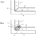
- the components A, B to be joined are positioned and fixed relative to one another in a tool 24, as shown in FIG 3 shown.
- a gap 25 between the components which allows later injection of the thermoplastic "mastic" formed by the thermoplastic melt.
- very precise component tolerances can also be achieved in this way.
- the injection nozzle 18 is brought up to the core composite elements or components 11 and the introduction or injection of the melt 17 in the injection direction E into the gap 25 begins.
- the melt 17 first fills the given gap 25.
- the Melt 17 pressed under the injection pressure in the direction of the flow arrows S in the two individual components A, B.
- the nozzle 18 moves along a joining seam as in a welding process.
- the melt flow in the direction of the gap is optionally controlled by a corresponding configuration of the nozzle 18 is mechanically limited.
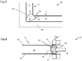
- melt 17 displaces the core structure 12 designed as a foam in the edge regions results from the melt 17 after the latter Cooling a bridge or a hinge 26 from the solidified thermoplastic material 19 between the individual components, as in figure 5 shown.
- the joined core composite elements 11 form a core composite component 10 which is reinforced by the cooled and thus solidified thermoplastic melt 17 or 19 , the reinforcement 50 being formed by the bridge or the hinge 26 .
- the component designed as a core composite element 11 is first cut out of a generic plate and made available.
- a movable injection device 27 is then placed on the edge of the component and moves around the component 11 along the contour of the component. The movement takes place in the direction of arrow V.
- An injection unit 28 is integrated in this device, which injects the heated thermoplastic melt 17 into the core composite element 11 (arrow E). The injection into the component edge takes place during the movement V.
- the thermoplastic material 17 penetrates in the direction of the flow arrow S into the core structure 12, i.e. on a side of the core composite element 11 that is exposed or not covered by one of the cover layers 13, 14 is.
- the core composite component 10 produced by the method can be post-processed, which contains a reinforcement 50 made of solidified thermoplastic material 19 .
- the reinforced core composite component 10 is cut in particular in such a way that the cutting edge 29 in the area of the core structure 12 through the Reinforcement 50 extends, and preferably not through, any remaining portion of core structure 12.
- the reinforcement 50 is formed as a thermoplastic edge reinforcement.
- the core composite component 10 produced can be used for connecting to another core composite component 10 of this type by thermoplastic welding, as in 8 shown.
- This shows the 9 an overhead stowage compartment ( OHSC) 30 or luggage compartment for an aircraft in a schematic spatial representation, which is provided with a load-bearing element 31 according to the invention.
- the load-bearing element 31 serves to harmonize the loads that occur in the luggage compartment or OHSC 30 with the permissible deformations.
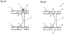
- FIG 10 shows the inserted element 31 between the two core composite elements 11 in an attached but not yet attached state.
- the load-bearing element 31 is designed as a strut, which has a projection 32 in the form on two opposite sides of a pin to attach the element or strut 31 to the opposing core composite elements 11 of the OHSC 30 .
- the composite core elements 11 are designed as described above in the previous exemplary embodiments and are provided for carrying out the method. Then the load-bearing element 31 is inserted between the two core composite elements 11 .
- the pins 32 protrude into through holes 16, which were previously formed as bores in the respective core assembly or core assembly element 11 and extend through it.
- the diameter of the respective pin 32 is smaller than the inner diameter 16 of the respective hole 16.
- the composite core elements 11 each lie on a bearing surface 33 of the element 31.
- the geometry and the number of pins 32 are to be regarded as exemplary.
- the load-bearing element 31 is preferably made of a thermoplastic which is, for example, fiber-reinforced. But it can also be made of another material such as metal.
- the pins 32 in the respective composite core element 11 are pressed flat under the action of pressure and temperature, that is to say deformed.
- the step is comparable to creating a rivet head.
- the pressure is exerted on the respective pin 32 in the direction of the arrows P, so that it is deformed. This state is in 11 shown.
- thermoplastic melt 17 As in 12 shown, is injected in a next heated thermoplastic melt 17 by means of an injection unit 18 in the holes 16 of both core composite elements 11 (arrow E).
- the heated melt 17 penetrates through the inner sides of the holes 16 into adjoining areas of the core structures 12 of the composite core elements 11, as described above for the other exemplary embodiments.
- thermoplastic melt 17 is then cooled, solidifying and forming a solidified thermoplastic region 23 after cooling, as shown in FIG 13 shown.
- the shaped pin 32 is fixed to the respective composite core element 11 and thereby connected to the composite core.
- the solidified thermoplastic area 23 forms a local reinforcement 50.
- the respective core composite element 11 forms a core composite component 10 with its local reinforcement 50, which is locally reinforced in the area where the load-bearing element 31 is connected.
- the geometry of the element 31 can also be in the form of an O-frame or C-frame, for example, with a correspondingly larger number of pins 32 for fixing.
- thermoplastic area 23 does not only have to be selective in order to integrate the strut.
- the thermoplastic can also be introduced as local or linear reinforcement independently of a load-bearing element.
- figure 14 shows a schematic sectional view of a core composite component 70 which, according to a further exemplary embodiment of the method according to the invention, has been provided with a multiplicity of load paths 71 which form reinforcements.
- the core composite component forms a bionic structure.
- a core composite element 11 is provided as described above. It comprises a core structure 12 sandwiched between relatively thin skin layers 13,14.
- the core structure 12 is designed, for example, as a foam structure in the form of a foam.
- the core structure 12 with the cover layers 13, 14 forms an undisturbed, finished foam core composite.
- the load paths 71 are formed by injection paths for the thermoplastic or for the thermoplastic material 17 . After the heated thermoplastic material 17 has been injected into the injection paths, which are designed as holes, by means of injection units 28, the thermoplastic melt 17 in the injection paths is cooled and solidified.
- the load paths 71 When using the described method for generating bionic load paths in core composites, the load paths 71 will be visible on the milled side after completion. The opposite side is undisturbed.
- the process described can also be applied to three-dimensional bodies and structures.
- thermoplastic material When injecting and curing the thermoplastic material, it can be advantageous if the injected thermoplastic material embeds the edges of the cover skins and thickens the component beyond the surface of the respective cover skin.
- the invention achieves the following advantages over the prior art: Only generic disks are required as a starting product. This results in reduced warehousing. Plate production is simplified. The cycle times are reduced because no cross-linking of adhesives is necessary, but the cooling of a melt. Milling out of the structure is also not necessary. Furthermore, the use of various thermoplastic materials is possible, also with fiber reinforcement.
- a Z reinforcement of the foam for example, is not damaged, but the Z pins are integrated into the melt. This also leads to an improved connection. Waste from milling out the honeycomb or core structure can be avoided. In addition, the process can be fully automated. There are no tolerance problems such as with plugs or plugs, since the melt adapts to the component status.
- the method is also applicable to honeycomb structures, for example. This causes the honeycomb to be displaced and the cells to be filled up.
Landscapes
- Engineering & Computer Science (AREA)
- Mechanical Engineering (AREA)
- Chemical & Material Sciences (AREA)
- Composite Materials (AREA)
- Laminated Bodies (AREA)
Abstract
Description
- Die Erfindung betrifft ein Verfahren zum Herstellen eines verstärkten Kernverbundbauteils, insbesondere für Luftfahrzeuge. Weiterhin betrifft die Erfindung ein Kernverbundbauteil und ein Luftfahrzeug.
- Kernverbunde bestehen per Definition aus einer Kernstruktur relativ großer Höhe bzw. Dicke, die zwischen zwei dünnen Decklagen angeordnet ist. Werden in diesen Verbunden Bereiche identifiziert, die einer erhöhten Belastung ausgesetzt sind so wird dieser Bereich lokal verstärkt. Dies erfolgt entweder durch den Einsatz von Kernstrukturen bzw. Bauteilen höherer Dichte oder aber durch das Einbringen von zum Beispiel Füllmassen.
- In offene Zellstrukturen kann nach dem Stand der Technik lokal ein Werkstoff mit erhöhter Viskosität eingebracht werden, der das Volumen zwischen den beiden Decklagen vollständig auffüllt. Die Masse wird vor der Applikation der Decklagen bzw. Deckhäute eingebracht und mit den Häuten oder Decklagen ausgehärtet.
- Diese Methode kann in der Fläche angewendet werden, aber auch im Bereich späterer Schnittkanten. Wird im Bereich der gefüllten Zellen geschnitten, ist der Rand bzw. die Kante gleichzeitig stabilisiert. Diese Methode wird zum Beispiel bei Fußbodenplatten im Kabinenbereich von Flugzeugen angewendet, um die Kanten gegen Schädigung durch Rollenbelastung z.B. von Food Trolleys zu stabilisieren.
- Gerade bei der Fertigung von Fußbodenplatten für Flugzeug wird eine weitere bekannte Methodik zur lokalen Verstärkung und späteren Bauteilanbindung angewendet. Dabei werden vor der Applikation der Deckhäute zylindrische Plugs bzw. Stopfen in die Wabe eingelegt. Im fertigen Verbund werden diese durchbohrt.
- Die Plugs oder Stopfen dienen der Anbindung und Kraftübertragung zwischen Platte und Bodenstruktur.
- Eine weitere bekannte Möglichkeit, um lokal Anbindungen im Kernverbund zu generieren, ist das nachträgliche Einbringen von Inserts bzw. Einlegern. Hierzu wird ein definiertes Loch in den Verbund gebohrt, der dem späteren Insertdurchmesser entspricht. In einem zweiten Bearbeitungsschritt wird die Wabe zum Beispiel auf den 1,5-fachen Bohrungsdurchmesser ausgefräst und so eine Hinterschneidung generiert. Anschließend wird das Insert eingesetzt und die Kavität im Wabeninneren mit Klebstoff gefüllt. Im Gegensatz zu Methoden, bei denen die Füllmasse und der Einleger bzw. das Insert mit dem Aushärten der Deckhäute konsolidiert werden, erfordert das nachträgliche Einkleben von Inserts eine zusätzliche Härtungszeit und möglicherweise eine weitere Temperaturbehandlung in Abhängigkeit von der Werkstoffauswahl.
- Um einen dreidimensionalen Körper herzustellen, ist es erforderlich zugeschnittene Platten zu fügen. Dabei ein Klebstoff erforderlich, um die beiden Teile unabhängig von der Stoßart miteinander kraftschlüssig zu verbinden. Zusätzlich kann die Kante vorab mit der oben beschriebenen Methode mit Füllmasse verstärkt werden.
- Um geforderte Toleranzen zu erfüllen, ist der Einsatz von Werkzeugen erforderlich, die die Einzelteile bis zur vollständigen Vernetzung der Klebstoffe in Position halten. Je nach Standzeit und Produktionsrate ist dazu eine größere Anzahl von Werkzeugen erforderlich. Die Anzahl wiederum spiegelt sich in den NRC-Kosten wider.
- Bei bekannten Technologien zum Erzeugen lokaler Verstärkungen oder Befestigungspunkte in Sandwichkonstruktionen werden diese zumeist vor dem Anbringen beider Decklagen appliziert. Typischerweise werden Stecker oder Vergussteile in den Kern bzw. die Kernstruktur eingesetzt und zusammen mit den Decklagen ausgehärtet. Eine erforderliche individuelle Ausgestaltung der Sandwichkonstruktion bzw. Platte muss deshalb bereits in einem frühen Stadium erfolgen, was zur Folge hat, dass eine große Menge an Teilen vorbereitet und gelagert bzw. vorgehalten werden muss.
- Wie eingangs beschrieben werden lokale Verstärkungen in Wabenverbunden nach dem Stand der Technik durch Auffüllen der Wabenzellen oder durch Einsetzen von Stopfen erreicht. Letztere sind bei Schaumstoffen auch denkbar. Das Einbringen von Füllmassen ist aufgrund der geschlossenen Porosität aber nur nach vorheriger Schaffung von freiem Volumen durch mechanischen Austragt möglich. Weiterhin sind die Methoden nur vor der Applikation der Deckhäute anwendbar. Es ist also nicht möglich generische Platten nach diesen Methoden im Nachgang anzupassen.
- Die Erfindung hat sich zur Aufgabe gestellt, bei der Herstellung von Kernverbundbauteilen die Zykluszeiten zu reduzieren, die Flexibilität zu erhöhen und eine möglichst späte spezifische bzw. kundenspezifische Differenzierung zu ermöglichen. Weiterhin soll die Anzahl der vorzuhaltenden Teile reduziert sowie der Automatisierungsgrad und der Output bzw. die Produktionsrate erhöht werden.
- Zum Lösen dieser Aufgabe schafft die Erfindung Verfahren zum Herstellen eines verstärkten Kernverbundbauteils gemäß Patentanspruch 1.
- Vorteilhafte Ausgestaltungen sind Gegenstand der Unteransprüche.
- Gemäß einem Aspekt schafft die Erfindung ein Verfahren zum Herstellen eines lokal verstärkten Kernverbundbauteils, insbesondere für Luftfahrzeuge, umfassend die Schritte:
- Bereitstellen mindestens eines Kernverbundelements, das eine Kernstruktur umfasst, die zwischen relativ dünnen Decklagen angeordnet ist, wobei die Kernstruktur als eine Schaumstruktur und/oder Wabenstruktur ausgebildet ist;
- Einbringen einer erhitzten thermoplastischen Schmelze in einen oder mehrere Teilbereiche der Kernstruktur;
- Abkühlen der thermoplastischen Schmelze in der Kernstruktur, um ein Kernverbundbauteil mit einer lokalen Verstärkung zu bilden.
- Insbesondere ermöglicht die Erfindung unter anderem das Einbringen von Füllmassen auch bei einer geschlossenen Porosität der Kernstruktur. Nach dem erfindungsgemäßen Verfahren wird zum Beispiel ein schaumbasierter Kernverbund im Nachgang mit lokalen Anbindungen und Verstärkungen versehen.
- Durch die Erfindung werden zudem die Zykluszeitenzeiten reduziert. Weiterhin wird anstatt einer großen Anzahl individueller Teile nur noch eine kleine Anzahl generischer, fertiger Teile bzw. Kernverbundelemente benötigt, die im Nachgang individuell angepasst oder bearbeitet werden. Darüber hinaus wird anstatt manueller Arbeit eine Automatisierung zum Beispiel durch CNC Verfahren ermöglicht. Zudem bleibt in durch Pins oder Stifte verstärkten Schaumstoff-Sandwichbauteilen die Verbindungsfläche für die Pins oder Faserpins intakt.
- Bevorzugt ist die Kernstruktur als eine Schaumstruktur wie zum Beispiel Schaumstoff ausgebildet.
- Bevorzugt erfolgt das Einbringen der Schmelze unter Druck.
- Vorteilhaft ist der Druck beim Einbringen der thermoplastischen Schmelze derart bemessen, dass sie die Schaumstruktur in dem Teilbereich der Kernstruktur verdrängt.
- Beispielsweise sind neben dem Druck auch die Temperatur und die Viskosität der Schmelze Kontrollparameter bei der Durchführung des Verfahrens.
- Die Kernstruktur kann auch als eine Wabenstruktur ausgebildet sein.
- Zum Beispiel kann vor dem Einbringen bzw. Einpressen der Schmelze ein Teil der Kernstruktur entfernt werden, um dort die Schmelze einzubringen.
- Bevorzugt wird der Druck beim Einbringen der Schmelze derart reduziert, dass ein weiterer Vorschub der Schmelze innerhalb der Kernstruktur durch deren beginnende Abkühlung und Verfestigung an der Front gestoppt wird und gleichzeitig ein Schrumpfen des Volumens der Schmelze innerhalb der Kernstruktur verhindert wird
- Bevorzugt wird zumindest in einer der Decklagen mindestens eine Öffnung zum Einbringen der Schmelze in die Kernstruktur eingebracht, wobei die Öffnung als zum Beispiel als Bohrung oder als Spalt ausgebildet wird und sich vorteilhafterweise zumindest teilweise in die Kernstruktur oder durch diese hindurch erstreckt.
- Der Spalt kann zum Beispiel als eine Nut ausgebildet werden.
- Insbesondere kann die Öffnung nach dem Einbringen der Schmelze durch diese thermoplastisch verschlossen werden.
- Beispielsweise wird die Öffnung durch Bohren oder Fräsen erzeugt, um zum Beispiel einen Spalt bzw. Frässpalt zu bilden.
- Bevorzugt drückt beim Einbringen der Schmelze ein Anpresselement im Bereich der Öffnung gegen die Decklage.
- Vorteilhaft wird beim Erzeugen des Spalts durch Fräsen gleichzeitig die erhitzte thermoplastische Schmelze in den sich bildenden Spalt eingepresst.
- Bevorzugt wird das Kernverbundbauteil nach dem Abkühlen und Verfestigen der thermoplastischen Schmelze im Bereich des Spalts geschnitten, um zum Beispiel eine Kantenverstärkung im Bereich der Kernstruktur zu bilden.
- Bevorzugt wird in Schritt (a) ein weiteres Kernverbundelement zum Anfügen an das erste Kernverbundbauteil bereitgestellt, wobei die beiden Kernverbundelemente derart positioniert werden, dass ihre Kernstrukturen voneinander beabstandet nebeneinander liegen und einen Fügespalt bilden.
- Vorteilhaft wird in Schritt (b) die erhitzte thermoplastische Schmelze in den Fügespalt gedrückt, um sie in mindestens einen Teilbereich der jeweiligen Kernstruktur beider Kernverbundelemente einzupressen.
- Bevorzugt wird das bereitgestellte Kernverbundelement aus einer Kernverbundplatte geschnitten.
- Vorteilhaft wird die erhitzte thermoplastische Schmelze fortlaufend und/oder oder umlaufend entlang der Kontur des Kernverbundelements in die Kernstruktur injiziert, um eine Kantenverstärkung zu bilden.
- Bevorzugt werden zwei mit dem Verfahren hergestellte Kernverbundbauteile im Bereich ihrer Kantenverstärkungen durch thermoplastisches Schweißen miteinander verbunden.
- Vorteilhaft wird in der Öffnung ein Vorsprung eines lasttragenden Elements angeordnet, der zum Beispiel unter Einwirkung von Druck und Temperatur innerhalb der Öffnung zusammengepresst wird, und anschließend wird die erhitzte thermoplastische Schmelze in die Öffnung mit dem darin befindlichen Vorsprung injiziert, um das Kernverbundelement thermoplastisch mit dem lasttragenden Element zu verbinden.
- Bevorzugt werden zwei oder mehr Kernverbundelemente beabstandet voneinander mit jeweils mindestens einem Vorsprung des lasttragenden Elements verbunden, um mit dem lasttragenden Element ein verstärktes Bauteil zu bilden.
- Bevorzugt werden mehrere Öffnungen derart in der Kernstruktur ausgebildet, dass sie nach Einbringen und Abkühlen der thermoplastischen Schmelze Lastpfade einer bionischen Struktur bilden.
- Mit dem hier beschriebenen Verfahren wird insbesondere ein Werkstück bearbeitet, das durch das Kernverbundelement gebildet wird.
- Gemäß einem anderen Aspekt schafft die Erfindung ein Kernverbundbauteil, umfassend eine Kernstruktur, die zwischen relativ dünnen Decklagen angeordnet ist, wobei die Kernstruktur als eine Schaumstruktur und/oder Wabenstruktur ausgebildet ist, und wobei in einem Teilbereich der Kernstruktur eine in der Kernstruktur erstarrte thermoplastische Schmelze als lokale Verstärkung angeordnet ist.
- Bevorzugt ist das Kernverbundbauteil mit dem erfindungsgemäßen Verfahren hergestellt.
- Insbesondere ist das Kernverbundbauteil ein Gepäckfach bzw. Overhead Stowage Compartment oder ein Teil davon.
- Gemäß einem weiteren Aspekt schafft die Erfindung ein Luftfahrzeug, das ein Kernverbundbauteil umfasst, das mit dem erfindungsgemäßen Verfahren hergestellt ist und/oder ein erfindungsgemäßes Kernverbundbauteil umfasst.
- Vorteile, Details, und Merkmale, die im Zusammenhang mit dem erfindungsgemäßen Verfahren beschrieben sind, gelten jeweils wechselseitig auch für die anderen Aspekte der Erfindung.
- Ausführungsbeispiele der Erfindung werden im Folgenden anhand der beigefügten Zeichnungen näher erläutert. Darin zeigen:
- Figur 1
- ein Kernverbundelement in schematischer Schnittdarstellung in verschiedenen Phasen des erfindungsgemäßen Verfahrens gemäß einem ersten bevorzugten Ausführungsbeispiel;
- Figur 2
- ein Kernverbundelement in schematischer Schnittdarstellung in verschiedenen Phasen des erfindungsgemäßen Verfahrens gemäß einem zweiten bevorzugten Ausführungsbeispiel;
- Figuren 3 bis 5
- zwei Kernverbundelemente in schematischer Schnittdarstellung, die gemäß einem dritten bevorzugten Ausführungsbeispiel des erfindungsgemäßen Verfahrens aneinander fixiert werden;
- Figur 6
- ein Kernverbundelement in schematischer Schnittdarstellung, das gemäß einem vierten bevorzugten Ausführungsbeispiel des erfindungsgemäßen Verfahrens zur Bauteilfügung vorbereitet wird;
- Figuren 7 und 8
- das in
Figur 6 gezeigte Kernverbundelement vor und nach dem Aneinanderfügen mit einem zweiten derartigen Kernverbundelement; - Figur 9
- ein Gepäckfach bzw. Overhead Stowage Compartment eines Flugzeugs in schematischer räumlicher Darstellung, das erfindungsgemäß mit einem lasttragenden Element versehen ist;
- Figuren 10-13
- verschiedene Schritte der Befestigung eines lasttragenden Elements in zwei gegenüberliegenden Kernverbundelementen des in
Fig. 9 gezeigten Gepäckfachs gemäß einem fünften Ausführungsbeispiel des erfindungsgemäßen Verfahrens; und - Figur 14
- eine schematische Schnittdarstellung eines Kernverbundbauteils, das gemäß einem weiteren Ausführungsbeispiel des erfindungsgemäßen Verfahrens mit Lastpfaden versehen ist und eine bionische Struktur bildet.
- In den Figuren sind gleiche oder einander entsprechende Elemente jeweils mit den gleichen Bezugszeichen bezeichnet und werden daher, sofern es nicht zweckmäßig erscheint, nicht erneut beschrieben. Die in der gesamten Beschreibung enthaltenen Offenbarungen sind sinngemäß auf gleiche Teile mit gleichen Bezugszeichen bzw. gleichen Bauteilbezeichnungen übertragbar. Auch sind die in der Beschreibung gewählten Lageangaben, wie z.B. oben, unten, seitlich usw. auf die unmittelbar beschriebene sowie dargestellte Figur bezogen und sind bei einer Lageänderung sinngemäß auf die neue Lage zu übertragen. Weiterhin können auch Einzelmerkmale oder Merkmalskombinationen aus den gezeigten und beschriebenen unterschiedlichen Ausführungsbeispielen für sich eigenständige, erfinderische oder erfindungsgemäße Lösungen darstellen.
-
Figur 1 zeigt den Prozessablauf bzw. die Schritte bei der Herstellung eines Kernverbundbauteils 10 in verschiedenen zeitlich aufeinanderfolgenden Phasen I bis IV als Schnittansicht. Die verschiedenen Phasen sind zur Veranschaulichung in der Figur durch gestrichelte Linien voneinander getrennt. In diesem Beispiel wird ein Kernverbundelement 11 in Form eines schaumbasierten Kernverbunds im Nachgang mit lokalen Anbindungen und Verstärkungen versehen. - In Phase I wird zunächst das Kernverbundelement 11 bereitgestellt. Es umfasst eine Kernstruktur 12, die zwischen zwei relativ dünnen Decklagen 13, 14 angeordnet ist. Die Kernstruktur 12 ist zum Beispiel aus einem Kunststoff gefertigt und als eine Schaumstruktur in Form eines Schaumstoffs ausgebildet. Die Kernstruktur 12 mit den Decklagen 13, 14 bildet einen ungestörten, fertigen Schaumkernverbund.
- In Phase II wird eine Öffnung 15 in Form einer Bohrung 16 in die obere Decklage 13 eingebracht, d. h. in eine Decklagenseite, in diesem Fall in die obere Decklage 13. Die Bohrung 16, die als ein Loch ausgebildet ist, erstreckt sich durch die Decklage 13 und in diesem Beispiel durch die gesamte Kernstruktur 12 bis zur gegenüberliegenden Decklagenseite, welche durch die untere Decklage 14 gebildet wird. Die Bohrung 16 muss sich jedoch nicht notwendigerweise durch die gesamte Kernstruktur 12 bis zur gegenüberliegenden Decklagenseite 14 erstrecken. Je nach Bohrungstiefe wird sich aber das Strömungsprofil bei dem nachfolgenden Verfahrensschritt verändern.
- In Phase III erfolgt nun das Einbringen einer erhitzten thermoplastischen Schmelze 17 in die Kernstruktur 12 bzw. in einen Teilbereich davon, wie durch den Pfeil E gekennzeichnet. Hierzu wird eine Einspritzdüse 18 auf die Bohrung 16 aufgesetzt. Nun wird durch die Düse 18 mit einem definierten Druck die thermoplastische Schmelze oder Thermoplastschmelze 17, die zum Beispiel auch ein thermoplastischer Heißklebstoff sein kann, in den Schaumverbund bzw. Schaumkernverbund eingepresst und gelangt in die Kernstruktur 12.
- Durch entsprechende Abstimmung der Temperatur der Schmelze 17 mit den Eigenschaften des Schaumstoffs, der die Kernstruktur 12 bildet, wird dieser zum lokalen Kollabieren gebracht. Durch den Druck der Düse 18 verdrängt die Schmelze 17 beim Einpressen fortschreitend den Schaumstoff bzw. die Kernstruktur 12 und wird diesen nach ihrem Abkühlen durch einen thermoplastischen bzw. voll thermoplastischen Stopfen 19 ersetzen, der durch das verfestigte thermoplastische Material gebildet wird
- Der Stopfen 19 und der Schaumstoff 12 verbinden sich während des Verfahrens optimal an der Front 20 der Schmelze bzw. verkleben sich. Dieser Prozess wird über den Druck beim Einpressen der Schmelze 17 geregelt, um eine optimale Verbindung bzw. Verklebung zu erzielen.
- Sobald eine ausreichende Menge an Schmelze 17 in die Kernstruktur 12 eingebracht ist, wird der Druck bzw. Einspritzdruck auf einen Haltedruck reduziert, wodurch ein weiterer Vorschub der Front 20 der Schmelze 17 gestoppt wird und gleichzeitig ein Schrumpfen der Schmelze 17 innerhalb der Kernstruktur 12 verhindert wird. Mit der Einspritzdauer steigt der Prozessdruck an, da die Schmelze 17 an der Front 20 bereits beginnt sich abzukühlen. Neben dem Druck sind auch die Temperatur der Schmelze 17 und deren Viskosität weitere Kontrollfaktoren beim Einpressen der Schmelze 17. Die erforderlichen Einstellungen werden so vorgenommen, dass die Schmelze 17 den Schaumstoff verdrängt, welcher die Kernstruktur 12 bildet, jedoch keinen unkontrollierten Kollaps verursacht.
- Um zu verhindern, dass die Deckhäute 13 bzw. 14 des Kernverbundelements 11 abgelöst werden, kann zusätzlich im Bereich der Einspritzung, d. h. in der Nähe der Einspritzdüse 18, ein in der Figur nicht dargestellter Niederhalter vorgesehen werden, sofern dies erforderlich ist. Der Niederhalter presst in diesem Fall das Werkstück bzw. das Kernverbundelement 11 gegen eine Auflagefläche, ähnlich dem Nähfuß einer Nähmaschine.
- Nach dem vollständigen Abkühlen der Schmelze 17 bzw. des Werkstücks, das nun durch das mit dem erstarrten thermoplastischen Material befüllte Kernverbundelement 11 gebildet wird, kann dieses lokal bearbeitet und insbesondere gebohrt und gesenkt werden, wie in der Figur in Phase IV dargestellt. Die abgekühlte thermoplastische Schmelze 17 innerhalb der Kernstruktur 12 bildet nun eine lokale Verstärkung 50 des Kernverbundelements 11, das auf diese Weise ein verstärktes Kernverbundbauteil bildet. Das lokal verstärkte Kernverbundbauteil 10 wird gemäß dem Verfahren zum Beispiel mit ein oder mehreren lokalen Anbindungen versehen.
- Das Werkstück kann abschließend auch lediglich plan gefräst werden, beispielsweise wenn nur eine lokale Verstärkung ohne Anbindungscharakter erforderlich ist. In diesem Fall ist das Loch oder Bohrloch 16, wie es in Phase II gebildet wurde, thermoplastisch verschlossen.
-
Fig. 2 zeigt schematisch zeitlich aufeinanderfolgende Phasen I bis VI bei der Durchführung des erfindungsgemäßen Verfahrens gemäß einem weiteren Beispiel, wobei hier eine Randverstärkung gebildet wird. Dabei werden in dem gezeigten Beispiel insbesondere umlaufende Kernverbundkanten verstärkt. - Bei Kernverbunden bedeuten Schnittkanten im Verbundbereich auch gleichzeitig Instabilitäten. Durch das Verfahren werden die Außenkonturen verstärkt. In dem nachfolgend beschriebenen Beispiel für das erfindungsgemäße Verfahren kommen vergleichbare Prozesse und Werkstoffe zum Einsatz wie bei der Bildung der lokalen Verstärkung in dem vorhergehend beschriebenen Beispiel.
- In Phase I wird zunächst ein ungestörter, fertiger Schaumkernverbund als Kernverbundelement 11 bereitgestellt. Dieses ist wie oben beschrieben ausgebildet (Schritt 1).
- In Phase II erfolgt ein erstes Konturfräsen des späteren Bauteils. Die Fräsung schneidet im einfachsten Fall nur eine Decklage, in diesem Beispiel die obere Decklage 13, und in der stärksten Ausprägung die komplette Kernstruktur 12. Die rückseitige bzw. untere Decklage 14 bleibt ungestört. Es bildet sich dadurch als Öffnung 15 ein Frässpalt bzw. eine Fräsnut 21, der sich durch die Decklage 13 und durch die Kernstruktur 12 hindurch erstreckt (Schritt 2).
- In Phase III wird der heiße thermoplastische Werkstoff 17 in den Frässpalt 21 eingepresst (Schritt 3). Dabei gelten vergleichbare Zusammenhänge aus Druck und Temperatur zur Prozesssteuerung wie sie bereits zu
Figur 1 beschrieben wurden. Da es sich um eine umlaufende Verstärkung handelt, die in diesem Beispiel gebildet wird, kommt zusätzlich ein Vorschub der Düse 18 bzw. der Düsenvorschub als Steuergröße im Prozess hinzu. Der Düsenvorschub verläuft in Längsrichtung des Spalts 21, das heißt senkrecht zur Zeichenebene derFigur 2 . - Gegebenenfalls werden die Schritte 2 und 3 kombiniert. In diesem Fall läuft der fortschreitende Frässchritt vor der Einspritzdüse 18 her. Dadurch kann verhindert werden, dass eine vollständige Vorbereitung der Fräsnut 21 zu einem Druckabfall beim Einbringen der Schmelze 17 führt, der mit den gegebenen Prozessparametern nicht kompensiert werden kann.
- Die Ausbreitung der Schmelze 17 mit der Front 20 erfolgt wie oben zu
Fig. 1 beschrieben. - In Phase IV erfolgt Schritt 4, in dem die Schmelze 17 abgekühlt wird. Die Schmelze 17 ist nun in die Kernstruktur 12 eingebracht und bildet einen Bereich mit verfestigtem thermoplastischen Material 19, das heißt eine eingespritzte Kante, die in der Figur als Querschnitt dargestellt ist. Auf diese Weise wird aus dem Kernverbundelement 11 ein lokal verstärktes Kernverbundbauteil 10 mit einer Verstärkung 50. Je nach Frästiefe bei der Vorbereitung kann sich der Profilquerschnitt auch andersartig ausbilden. Dieses Verhalten kann auch genutzt werden um eine gewichtsoptimierte Kantenverstärkung zu erreichen.
- In Phase V wird in einem weiteren Schritt das verstärkte Kernverbundbauteil 10 im Bereich des verfestigten thermoplastischen Materials 19 aus der Trägerplatte bzw. dem lokal verstärkten Kernverbundbauteil 10 herausgeschnitten. Gegebenenfalls erfolgt vorab eine Überfräsung der Einspritzbereiche, um überstehende Thermoplastrückstände zu entfernen.
- In Phase VI ist das Kernverbundbauteil in zwei voneinander getrennte Kernverbundbauteile mit jeweils lokaler Verstärkung 50 geteilt. Aufgrund des Verfahrens haben ihre beiden Schnittkanten 22 eine zusätzliche Kantenverstärkung im Bereich der Kernstruktur 12, die durch das verfestigte Thermoplastmaterial 19 bzw. durch die lokale Verstärkung 50 gebildet wird. Es kann dabei von Vorteil sein, den thermoplastischen Bereich 23 der Einspritzung im Bereich der Deckhaut bzw. Decklage 13 des Verbundes als zusätzlichen Stoßschutz zu nutzen.
- Vorteilhaft kann die Düsengeometrie so modifiziert werden, dass der Thermoplast vollständig, oder aber zumindest hauptsächlich in ein Schnittufer eingebracht wird. Das ist vor allem dann vorteilhaft, wenn nur eine Seite später zur Anwendung kommt.
- Anhand der
Figuren 3 bis 5 wird nachfolgend ein weiteres Beispiel des erfindungsgemäßen Verfahrens beschrieben, bei dem zwei Kernverbundelemente 11 aneinandergefügt werden. Beispielsweise erfordert die Herstellung dreidimensionaler Strukturen aus ebenen Bauteilen das Fügen verschiedener Komponenten. - Zunächst werden die zu fügenden Komponenten A, B, die jeweils als ein Kernverbundelement 11 wie oben beschrieben ausgebildet sind, in einem Werkzeug 24 relativ zueinander positioniert und fixiert, wie in
Fig. 3 gezeigt. Idealerweise besteht zwischen den Komponenten ein Spalt 25, der das spätere Einspritzen der thermoplastischen "Fügemasse" ermöglicht, die durch die thermoplastische Schmelze gebildet wird. Je nach Gestaltung des Werkzeugs 24 können so auch sehr präzise Bauteiltoleranzen erreicht werden. - Wie in
Fig. 4 gezeigt wird in einem nächsten Schritt die Einspritzdüse 18 an die Kernverbundelemente oder Bauteile 11 herangeführt und es beginnt das Einbringen bzw. Einspritzen der Schmelze 17 in der Einspritzrichtung E in den Spalt 25. Dabei füllt die Schmelze 17 zunächst den gegebenen Spalt 25. Anschließend wird die Schmelze 17 unter dem Einspritzdruck in Richtung der Strömungspfeile S in die beiden Einzelkomponenten A, B gedrückt. Zur Fügung bewegt sich die Düse 18 entlang einer Fügenaht wie bei einem Schweißvorgang. Um zu verhindern, dass es durch den existierenden Spalt 25 zwischen den Einzelkomponenten A, B zu einem Druckverlust kommt, das heißt zu einem Ausbreiten der Schmelze 17 in Spaltrichtung und nur unzureichend in die Einzelkomponenten A, B, wird der Schmelzefluss in Spaltrichtung gegebenenfalls durch eine entsprechende Ausgestaltung der Düse 18 mechanisch begrenzt. - Dadurch, dass die Schmelze 17 die als Schaumstoff ausgebildete Kernstruktur 12 in den Randbereichen verdrängt, entsteht aus der Schmelze 17 nach deren Abkühlen eine Brücke bzw. ein Scharnier 26 aus dem verfestigten thermoplastischen Material 19 zwischen den Einzelbauteilen, wie in
Fig. 5 gezeigt. Die aneinandergefügten Kernverbundelemente 11 bilden auf diese Weise ein Kernverbundbauteil 10, das durch die abgekühlte und somit verfestigte thermoplastische Schmelze 17 bzw. 19 verstärkt ist, wobei die Verstärkung 50 durch die Brücke bzw. das Scharnier 26 gebildet wird. - Anhand von
Fig. 6 wird nun ein weiteres Ausführungsbeispiel des erfindungsgemäßen Verfahrens erläutert, bei dem eine Kantenvorbereitung zur Fügung von Bauteilen mittels Schweißen erfolgt. - Dabei wird das als Kernverbundelement 11 ausgebildete Bauteil zunächst aus einer generischen Platte ausgeschnitten und bereitgestellt.
- Anschließend wird auf die Bauteilkante eine bewegbare Injektionsvorrichtung 27 aufgesetzt, die sich entlang der Bauteilkontur um das Bauteil 11 herumbewegt. Die Bewegung erfolgt in Richtung des Pfeils V. In dieser Vorrichtung ist eine Injektionseinheit 28 integriert, die die aufgeheizte Thermoplastschmelze 17 in das Kernverbundelement 11 einspritzt (Pfeil E). Die Injektion in die Bauteilkante erfolgt während der Bewegung V. Das thermoplastische Material 17 dringt in Richtung der Strömungspfeile S in die Kernstruktur 12 ein, das heißt an einer Seite des Kernverbundelements 11, die frei liegt bzw. nicht von einer der Decklagen 13, 14 überdeckt ist.
- Nach abgeschlossenem Umlauf der Injektionsvorrichtung 27 und dem Abkühlen der thermoplastischen Schmelze 17 kann eine Nachbearbeitung des durch das Verfahren hergestellten Kernverbundbauteils 10 erfolgen, welches eine Verstärkung 50 aus verfestigtem thermoplastischem Material 19 enthält.
- Beispielsweise erfolgt bei der Nachbearbeitung eine Vorbereitung für die Fügung mit einem weiteren, gleichartig ausgebildeten Kernverbundbauteil 10, wie in
Fig. 7 gezeigt. Dabei wird das verstärkte Kernverbundbauteil 10 insbesondere derart geschnitten, dass die Schnittkante 29 im Bereich der Kernstruktur 12 durch die Verstärkung 50 verläuft, und bevorzugt nicht durch einen übrigen Bereich der Kernstruktur 12. - Auf diese Weise wird die Verstärkung 50 als eine thermoplastische Kantenverstärkung ausgebildet.
- Aufgrund seiner thermoplastischen Kantenverstärkung 50 kann das hergestellte Kernverbundbauteil 10 zum Verbinden mit einem weiteren derartigen Kernverbundbauteil 10 durch thermoplastisches Schweißen verwendet werden, wie in
Fig. 8 gezeigt. Dadurch wird ein aus mehreren verstärkten Kernverbundbauteilen 10 zusammengefügtes, thermoplastisch verschweißtes Kernverbundbauteil 60 geschaffen, das eine Verstärkung 50 aufweist, die durch das verfestigte thermoplastische Material 19 beider Kernverbundbauteile 10 gebildet ist. - Anhand der
Figuren 9 bis 13 wird ein weiteres Anwendungsbeispiel des erfindungsgemäßen Verfahrens beschrieben, bei dem lasttragende Elemente in Kernstrukturen von Kernverbundbauteilen verankert werden. - Hierzu zeigt die
Fig. 9 ein Overhead Stowage Compartment (=OHSC) 30 bzw. Gepäckfach für ein Flugzeug in schematischer räumlicher Darstellung, das erfindungsgemäß mit einem lasttragenden Element 31 versehen ist. Das Lasttragende Element 31 dient dazu, im Gepäckfach bzw. OHSC 30 die auftretenden Lasten und die zulässigen Verformungen in Einklang zu bringen. - Gemäß diesem Ausführungsbeispiel des erfindungsgemäßen Verfahrens sind folgende Schritte vorgesehen, die anhand der
Figuren 10 bis 13 erläutert werden, welche jeweils als schematische Schnittansicht ein exemplarisches lasttragendes Element 31 zwischen zwei sich gegenüberliegenden Kernverbundelementen 11 des OHSC 30 zeigen. -
Figur 10 zeigt das eingesetzte Element 31 zwischen den beiden Kernverbundelementen 11 in einem angefügten, jedoch noch nicht befestigten Zustand. Das lasttragende Element 31 ist als ein Strut bzw. eine Strebe ausgebildet, die an zwei sich gegenüber liegenden Seiten jeweils einen Vorsprung 32 in Form eines Zapfens aufweist, um das Element bzw. den Strut 31 an den sich gegenüberliegenden Kernverbundelementen 11 des OHSC 30 zu befestigen. - Die Kernverbundelemente 11 sind wie oben in den vorhergehenden Ausführungsbeispielen beschrieben ausgebildet und werden zur Durchführung des Verfahrens bereitgestellt. Anschließend wird das lasttragende Element 31 zwischen den beiden Kernverbundelementen 11 eingesetzt.
- Im eingesetzten Zustand ragen die Zapfen 32 in durchgehende Löcher 16, die zuvor als Bohrungen in dem jeweiligen Kernverbund bzw. Kernverbundelement 11 ausgebildet wurden und sich durch dieses hindurch erstrecken. Der Durchmesser des jeweiligen Zapfens 32 ist geringer als der Innendurchmesser 16 des jeweiligen Lochs 16. Die Kernverbundelemente 11 liegen jeweils auf einer Auflagefläche 33 des Elements 31 auf.
- Die Geometrie und die Anzahl der Zapfen 32 sind als exemplarisch zu betrachten. Das lasttragende Element 31 ist vorzugsweise aus einem Thermoplast gefertigt, das zum Beispiel faserverstärkt ist. Es kann aber auch aus einem anderen Material wie zum Beispiel aus Metall gefertigt sein.
- In einem nächsten Schritt werden die Zapfen 32 im jeweiligen Kernverbundelement 11 unter Einwirkung von Druck und Temperatur flach gedrückt, also umgeformt. Der Schritt ist vergleichbar der Erzeugung eines Nietkopfes. Dabei wird der Druck in Richtung der Pfeile P auf den jeweiligen Zapfen 32 ausgeübt, so dass er umgeformt wird. Dieser Zustand ist in
Fig. 11 gezeigt. - Wie in
Fig. 12 dargestellt, wird in einem nächsten erhitzte thermoplastische Schmelze 17 mittels einer Injektionseinheit 18 in die Löcher 16 beider Kernverbundelemente 11 injiziert (Pfeil E). Dabei dringt die erhitzte Schmelze 17 wie oben zu den anderen Ausführungsbeispielen beschrieben in über die Innenseiten der Löcher 16 in angrenzende Bereiche der Kernstrukturen 12 der Kernverbundelemente 11 ein. - Anschließend wird die thermoplastische Schmelze 17 abgekühlt, wobei sie sich verfestigt und nach dem Abkühlen einen verfestigten thermoplastischen Bereich 23 bildet, wie in
Fig. 13 gezeigt. Durch das Injizieren und Abkühlen der thermoplastischen Schmelze 17 wird der umgeformte Zapfen 32 an das jeweilige Kernverbundelement 11fixiert und dadurch an den Kernverbund angebunden. In diesem Zustand bildet der verfestigte thermoplastische Bereich 23 eine lokale Verstärkung 50. Das jeweilige Kernverbundelement 11 bildet auf diese Weise mit seiner lokalen Verstärkung 50 ein Kernverbundbauteil 10, das im Bereich der Anbindung des lasttragenden Elements 31 lokal verstärkt ist. - Die Geometrie des Elements 31 kann zum Beispiel auch in Form eines O-Rahmens oder C-Rahmens ausgebildet sein mit entsprechend mehr Zapfen 32 zur Fixierung.
- Der thermoplastische Bereich 23 muss nicht nur punktuell sein, um den Strut einzubinden. Das Thermoplast kann auch als lokale oder linienförmige Verstärkung unabhängig von einem lasttragenden Element eingebracht werden.
-
Figur 14 zeigt eine schematische Schnittdarstellung eines Kernverbundbauteils 70, das gemäß einem weiteren Ausführungsbeispiel des erfindungsgemäßen Verfahrens mit einer Vielzahl von Lastpfaden 71 versehen wurde, welche Verstärkungen bilden. Das Kernverbundbauteil bildet auf diese Weise eine bionisch ausgelegte Struktur. - Bei der Herstellung wird wie oben beschrieben ein Kernverbundelement 11 bereitgestellt. Es umfasst eine Kernstruktur 12, die zwischen relativ dünnen Decklagen 13, 14 angeordnet ist. Die Kernstruktur 12 ist zum Beispiel als eine Schaumstruktur in Form eines Schaumstoffs ausgebildet. Die Kernstruktur 12 mit den Decklagen 13, 14 bildet einen ungestörten, fertigen Schaumkernverbund.
- Die Lastpfade 71 werden durch Einspritzbahnen für den Thermoplast bzw. für das thermoplastische Material 17 gebildet. Nach dem Einspritzen des erhitzten thermoplastischen Materials 17 in die als Löcher ausgebildeten Einspritzbahnen mittels Injektionseinheiten 28 erfolgt das Abkühlen und Verfestigen der thermoplastischen Schmelze 17 in den Einspritzbahnen.
- Bei Anwendung der beschriebenen Methode zur Erzeugung von bionischen Lastpfaden in Kernverbunden werden nach Fertigstellung die Lastpfade 71 auf der gefrästen Seite sichtbar sein. Die gegenüberliegende Seite ist ungestört. Der beschriebene Prozess kann selbstverständlich auch auf dreidimensionale Körper und Strukturen angewendet werden.
- Beim Einspritzen und Aushärten des thermoplastischen Materials kann es von Vorteil sein, wenn das eingespritzte thermoplastische Material die Ufer der Deckhäute einbettet und über die Oberfläche der jeweiligen Deckhaut hinaus das Bauteil aufdickt.
- Durch die Erfindung werden insbesondere folgende Vorteile gegenüber dem Stand der Technik erzielt:
Es sind nur generische Platten als Ausgangsprodukt erforderlich. Dadurch ergibt sich eine reduzierte Lagerhaltung. Die Plattenfertigung wird vereinfacht. Die Zykluszeiten werden reduziert, da keine Vernetzung von Klebstoffen notwendig ist, sondern das Abkühlen einer Schmelze. Auch ist kein Ausfräsen der Struktur notwendig. Weiterhin ist der Einsatz von verschiedenen Thermoplastwerkstoffen möglich, auch mit Faserverstärkung. - Darüber hinaus wird zum Beispiel eine Z-Verstärkung des Schaumstoffs nicht beschädigt, sondern die Z-Pins werden in die Schmelze eingebunden. Das führt zusätzlich zu einer verbesserten Anbindung. Abfälle durch Ausfräsen der Waben- bzw. Kernstruktur können vermieden werden. Darüber hinaus ist das Verfahren ist voll automatisierbar. Es ergeben sich keine Toleranzprobleme wie beispielsweise bei Plugs oder Stopfen, da sich die Schmelze dem Bauteilstatus anpasst.
- Das Verfahren ist zum Beispiel auch anwendbar auf Wabenstrukturen. Dabei erfolgt ein Verdrängen der Wabe und das Auffüllen der Zellen.
-
- 10
- Kernverbundbauteil
- 11
- Kernverbundelement
- 12
- Kernstruktur
- 13, 14
- Decklagen
- 15
- Öffnung
- 16
- Bohrung, Loch
- 17
- thermoplastischen Schmelze
- 18
- Düse
- 19
- Verfestigtes thermoplastisches Material, Stopfen
- 20
- Front
- 21
- Spalt, Nut
- 22
- Schnittkanten
- 23
- verfestigter thermoplastischer Bereich
- 24
- Werkzeug
- 25
- Spalt, Fügespalt
- 26
- Brücke, Scharnier
- 27
- bewegbare Injektionsvorrichtung
- 28
- Injektionseinheit
- 29
- Schnittkante
- 30
- Gepäckfach / Overhead Stowage Compartment
- 31
- lasttragendes Element
- 32
- Vorsprung / Zapfen
- 33
- Auflagefläche
- 50
- Verstärkung
- 60
- thermoplastisch verschweißtes Kernverbundbauteil
- 70
- Kernverbundbauteil mit Lastpfaden
- 71
- Lastpfade
- A, B
- Komponenten
- E
- Einspritzrichtung
- P
- Druck auf Zapfen
- S
- Strömungsrichtung
- V
- Bewegung der Injektionsvorrichtung
Claims (15)
- Verfahren zum Herstellen eines lokal verstärkten Kernverbundbauteils, insbesondere für Luftfahrzeuge, umfassend die Schritte:a) Bereitstellen mindestens eines Kernverbundelements (11), das eine Kernstruktur (12) umfasst, die zwischen mindestens zwei relativ dünnen Decklagen (13, 14) angeordnet ist, wobei die Kernstruktur (12) als eine Schaumstruktur und/oder Wabenstruktur ausgebildet ist;b) Einbringen einer erhitzten thermoplastischen Schmelze (17) in einen oder mehrere Teilbereiche der Kernstruktur (12);c) Abkühlen der thermoplastischen Schmelze (17) in der Kernstruktur (12), um ein Kernverbundbauteil (10; 60; 70) mit einer lokalen Verstärkung (50; 71) zu bilden.
- Verfahren nach Anspruch 1, dadurch gekennzeichnet, dass das Einbringen der thermoplastischen Schmelze (17) unter Druck erfolgt, wobei der Druck derart bemessen ist, dass sie die Schaumstruktur in dem Teilbereich der Kernstruktur (12) verdrängt.
- Verfahren nach einem der vorhergehenden Ansprüche, dadurch gekennzeichnet, dass beim Einbringen der Schmelze (17) deren Druck derart reduziert wird, dass ein weiterer Vorschub der Schmelze (17) innerhalb der Kernstruktur durch deren beginnende Abkühlung und Verfestigung an ihrer Front (20) gestoppt wird und gleichzeitig ein Schrumpfen des Volumens der Schmelze (17) innerhalb der Kernstruktur (12) verhindert wird
- Verfahren nach einem der vorhergehenden Ansprüche, dadurch gekennzeichnet, dass zumindest in einer der Decklagen (13, 14) mindestens eine Öffnung (15) zum Einbringen der Schmelze (17) in die Kernstruktur (12) eingebracht wird, die als Bohrung (16) oder als Spalt (21) ausgebildet wird und sich zumindest teilweise in die Kernstruktur (12) oder durch diese hindurch erstreckt.
- Verfahren nach Anspruch 4, dadurch gekennzeichnet, dass beim Einbringen der Schmelze (17) ein Anpresselement im Bereich der Öffnung (15) gegen die Decklage (13, 14) drückt.
- Verfahren nach Anspruch 4 oder 5, dadurch gekennzeichnet, dass der Spalt (21) durch Fräsen erzeugt wird, wobei gleichzeitig die erhitzte thermoplastische Schmelze (17) in den sich bildenden Spalt (21) eingepresst wird.
- Verfahren nach Anspruch 6, dadurch gekennzeichnet, dass das Kernverbundbauteil (10) nach dem Abkühlen und Verfestigen der thermoplastischen Schmelze (17) im Bereich des Spalts (21) geschnitten wird, um eine Kantenverstärkung im Bereich der Kernstruktur (12) zu bilden.
- Verfahren nach einem der vorhergehenden Ansprüche, dadurch gekennzeichnet, dass- in Schritt (a) ein weiteres Kernverbundelement (11) zum Anfügen an das Kernverbundelement (11) bereitgestellt wird, wobei die beiden Kernverbundelemente (11) derart positioniert werden, dass ihre Kernstrukturen (12) voneinander beabstandet nebeneinander liegen und einen Fügespalt (25) bilden; und- in Schritt (b) die erhitzte thermoplastische Schmelze (17) in den Fügespalt (25) gedrückt wird, um sie in mindestens einen Teilbereich der jeweiligen Kernstruktur (12) einzupressen.
- Verfahren nach einem der vorhergehenden Ansprüche, dadurch gekennzeichnet, dass das bereitgestellte Kernverbundelement (11) aus einer Kernverbundplatte geschnitten wird, und die erhitzte thermoplastische Schmelze (17) fortlaufend und/oder oder umlaufend entlang der Kontur des Kernverbundelements (11) in die Kernstruktur (12) injiziert wird, um eine Kantenverstärkung zu bilden.
- Verfahren nach Anspruch 9, dadurch gekennzeichnet, dass zwei mit dem Verfahren hergestellte Kernverbundbauteile (10) im Bereich ihrer Kantenverstärkungen durch thermoplastisches Schweißen miteinander verbunden werden.
- Verfahren nach einem Anspruch 4 oder 5, dadurch gekennzeichnet, dass in der Öffnung (15) ein Vorsprung (32) eines lasttragenden Elements (31 angeordnet wird, der unter Einwirkung von Druck und Temperatur innerhalb der Öffnung (15) zusammengepresst wird,
und anschließend die erhitzte thermoplastische Schmelze (17) in die Öffnung (15) mit dem darin befindlichen Vorsprung (32) injiziert wird, um das Kernverbundelement (11) thermoplastisch mit dem lasttragenden Element (31 zu verbinden. - Verfahren nach Anspruch 11, dadurch gekennzeichnet, dass zwei oder mehr Kernverbundelemente (11) beabstandet voneinander mit jeweils mindestens einem Vorsprung (32) des lasttragenden Elements (31) verbunden werden, um mit dem lasttragenden Element (31) ein verstärktes Bauteil (30) zu bilden.
- Verfahren nach Anspruch 4 oder 5, dass mehrere Öffnungen (15) derart in der Kernstruktur (12) ausgebildet werden, dass sie nach Einbringen und Abkühlen der thermoplastischen Schmelze (17) Lastpfade (71) in einer bionischen Struktur (70) bilden.
- Kernverbundbauteil, umfassend
eine Kernstruktur (12), die zwischen mindestens zwei relativ dünnen Decklagen (13, 14) angeordnet ist,
wobei die Kernstruktur (12) als eine Schaumstruktur und/oder Wabenstruktur ausgebildet ist,
und wobei in einem Teilbereich der Kernstruktur (12) eine in der Kernstruktur (12) erstarrte thermoplastischen Schmelze (17) als lokale Verstärkung (50; 71) angeordnet ist. - Luftfahrzeug, dadurch gekennzeichnet, dass es ein Bauteil (30) umfasst, das mit einem Verfahren nach einem der Ansprüche 1 bis 13 hergestellt ist und/oder ein Kernverbundbauteil (10, 60, 70) gemäß Anspruch 14 umfasst.
Priority Applications (2)
| Application Number | Priority Date | Filing Date | Title |
|---|---|---|---|
| EP21186508.4A EP4122695B1 (de) | 2021-07-19 | 2021-07-19 | Verfahren zum herstellen eines verstärkten kernverbundbauteils, insbesondere für luftfahrzeuge, kernverbundbauteil und luftfahrzeug |
| CN202210846556.7A CN115636100A (zh) | 2021-07-19 | 2022-07-19 | 用于制造尤其用于飞行器的加强的芯复合构件的方法,芯复合构件和飞行器 |
Applications Claiming Priority (1)
| Application Number | Priority Date | Filing Date | Title |
|---|---|---|---|
| EP21186508.4A EP4122695B1 (de) | 2021-07-19 | 2021-07-19 | Verfahren zum herstellen eines verstärkten kernverbundbauteils, insbesondere für luftfahrzeuge, kernverbundbauteil und luftfahrzeug |
Publications (2)
| Publication Number | Publication Date |
|---|---|
| EP4122695A1 true EP4122695A1 (de) | 2023-01-25 |
| EP4122695B1 EP4122695B1 (de) | 2025-12-10 |
Family
ID=76971789
Family Applications (1)
| Application Number | Title | Priority Date | Filing Date |
|---|---|---|---|
| EP21186508.4A Active EP4122695B1 (de) | 2021-07-19 | 2021-07-19 | Verfahren zum herstellen eines verstärkten kernverbundbauteils, insbesondere für luftfahrzeuge, kernverbundbauteil und luftfahrzeug |
Country Status (2)
| Country | Link |
|---|---|
| EP (1) | EP4122695B1 (de) |
| CN (1) | CN115636100A (de) |
Cited By (1)
| Publication number | Priority date | Publication date | Assignee | Title |
|---|---|---|---|---|
| WO2025003615A1 (fr) | 2023-06-30 | 2025-01-02 | Safran Nacelles | Installation pour l'assemblage d'une ame d'un panneau et procede associe |
Citations (5)
| Publication number | Priority date | Publication date | Assignee | Title |
|---|---|---|---|---|
| US5192482A (en) * | 1989-02-17 | 1993-03-09 | Schreiner Luchtvaart Groep B.V. | Method of producing a local reinforcement in a sandwich structure |
| DE69008745T2 (de) * | 1989-02-17 | 1994-08-25 | Airex Ag | Sandwichplatte und Verfahren zur örtlichen Verstärkung einer Sandwichstruktur. |
| US20020157785A1 (en) * | 1997-12-23 | 2002-10-31 | The Boeing Company | Composite panel having a thermoplastic seam weld |
| FR2927012A1 (fr) * | 2008-02-06 | 2009-08-07 | Renault Sas | Methode de realisation d'une structure alveolaire |
| WO2011088871A2 (de) * | 2010-01-22 | 2011-07-28 | Daimler Ag | Sandwichbauteil und verfahren zu dessen herstellung |
-
2021
- 2021-07-19 EP EP21186508.4A patent/EP4122695B1/de active Active
-
2022
- 2022-07-19 CN CN202210846556.7A patent/CN115636100A/zh active Pending
Patent Citations (5)
| Publication number | Priority date | Publication date | Assignee | Title |
|---|---|---|---|---|
| US5192482A (en) * | 1989-02-17 | 1993-03-09 | Schreiner Luchtvaart Groep B.V. | Method of producing a local reinforcement in a sandwich structure |
| DE69008745T2 (de) * | 1989-02-17 | 1994-08-25 | Airex Ag | Sandwichplatte und Verfahren zur örtlichen Verstärkung einer Sandwichstruktur. |
| US20020157785A1 (en) * | 1997-12-23 | 2002-10-31 | The Boeing Company | Composite panel having a thermoplastic seam weld |
| FR2927012A1 (fr) * | 2008-02-06 | 2009-08-07 | Renault Sas | Methode de realisation d'une structure alveolaire |
| WO2011088871A2 (de) * | 2010-01-22 | 2011-07-28 | Daimler Ag | Sandwichbauteil und verfahren zu dessen herstellung |
Cited By (2)
| Publication number | Priority date | Publication date | Assignee | Title |
|---|---|---|---|---|
| WO2025003615A1 (fr) | 2023-06-30 | 2025-01-02 | Safran Nacelles | Installation pour l'assemblage d'une ame d'un panneau et procede associe |
| FR3150459A1 (fr) * | 2023-06-30 | 2025-01-03 | Safran Nacelles | Installation pour l’assemblage d’une ame d’un panneau et procede associe |
Also Published As
| Publication number | Publication date |
|---|---|
| CN115636100A (zh) | 2023-01-24 |
| EP4122695B1 (de) | 2025-12-10 |
Similar Documents
| Publication | Publication Date | Title |
|---|---|---|
| DE102017112881B4 (de) | Verfahren zum Verbinden von unterschiedlichen Materialwerkstücken | |
| DE3811427C2 (de) | ||
| DE102008001498B3 (de) | Verfahren und Umformvorrichtung zur Herstellung eines Faserverbundbauteils für die Luft- und Raumfahrt | |
| DE69822483T3 (de) | Lasttragendes fahrzeugdach und verfahren zu seiner herstellung | |
| EP2424716A2 (de) | Verfahren zur herstellung eines faserverbundbauteils für die luft- und raumfahrt | |
| DE10112635A1 (de) | Verfahren und Vorrichtung zum Zusammenformen eines thermoplastischen Materials mit einem thermoplastischen Sandwich-Material und dadurch hergestellte Artikel | |
| WO1993012344A1 (de) | Verfahren zum befestigen eines halteteils in einer ausnehmung eines bauteils | |
| DE60017833T2 (de) | SANDWICHPLATTE und Verfahren zu deren Herstellung | |
| DE102012016309A1 (de) | Verfahren zur Herstellung einer Kernschicht eines Leichtbauelementes sowie Leichtbauelement | |
| WO2012045476A1 (de) | Verfahren zur herstellung eines dekorteiles und ein solches dekorteil | |
| DE102008062020A1 (de) | Fahrradkurbel und Verfahren zu ihrer Herstellung | |
| EP2098317A1 (de) | Verfahren und Vorrichtung zum Herstellen eines Presslings aus Metallpulver | |
| DE102013109995A1 (de) | Verfahren zur Herstellung eines Bauteils aus einem Faserverbundwerkstoff mit einem Loch | |
| EP4122695B1 (de) | Verfahren zum herstellen eines verstärkten kernverbundbauteils, insbesondere für luftfahrzeuge, kernverbundbauteil und luftfahrzeug | |
| EP2993030B1 (de) | Faserverbundbauteil, klebeanordnung für faserverbundbauteile, sowie verfahren zur herstellung eines faserverbundbauteils und einer klebeanordnung | |
| DE102013021396B3 (de) | Fahrzeugbauteil mit einer Mehrschichtstruktur | |
| EP1144177B1 (de) | Spritzgiessvorrichtung zum hinterspritzen eines obermaterials mit kunststoff und verfahren | |
| DE102016210079B4 (de) | Verfahren zum Herstellen eines Rumpfabschnitts, Rumpfabschnitt und Luft- oder Raumfahrzeug | |
| EP4399990A2 (de) | Zehenkappe sowie verfahren zur herstellung einer solchen | |
| EP1626852B1 (de) | Verbundbauteil und verfahren zu dessen herstellung | |
| DE10338109B4 (de) | Verfahren zur Herstellung eines Verbundbauteils | |
| DE10024814A1 (de) | Herstellverfahren für ein Kunststoff-Sandwichbauteil | |
| EP3778179A1 (de) | Verfahren und vorrichtung zur herstellung eines bauteils | |
| DE102015212416B4 (de) | Gehäuse für ein Airbagmodul und Verfahren zur Herstellung eines solchen Gehäuses | |
| DE102006014313A1 (de) | Verfahren zur Herstellung eines Formteils |
Legal Events
| Date | Code | Title | Description |
|---|---|---|---|
| PUAI | Public reference made under article 153(3) epc to a published international application that has entered the european phase |
Free format text: ORIGINAL CODE: 0009012 |
|
| STAA | Information on the status of an ep patent application or granted ep patent |
Free format text: STATUS: THE APPLICATION HAS BEEN PUBLISHED |
|
| AK | Designated contracting states |
Kind code of ref document: A1 Designated state(s): AL AT BE BG CH CY CZ DE DK EE ES FI FR GB GR HR HU IE IS IT LI LT LU LV MC MK MT NL NO PL PT RO RS SE SI SK SM TR |
|
| STAA | Information on the status of an ep patent application or granted ep patent |
Free format text: STATUS: REQUEST FOR EXAMINATION WAS MADE |
|
| 17P | Request for examination filed |
Effective date: 20230725 |
|
| RBV | Designated contracting states (corrected) |
Designated state(s): AL AT BE BG CH CY CZ DE DK EE ES FI FR GB GR HR HU IE IS IT LI LT LU LV MC MK MT NL NO PL PT RO RS SE SI SK SM TR |
|
| GRAP | Despatch of communication of intention to grant a patent |
Free format text: ORIGINAL CODE: EPIDOSNIGR1 |
|
| STAA | Information on the status of an ep patent application or granted ep patent |
Free format text: STATUS: GRANT OF PATENT IS INTENDED |
|
| RIC1 | Information provided on ipc code assigned before grant |
Ipc: B32B 5/18 20060101AFI20250605BHEP Ipc: B32B 27/12 20060101ALI20250605BHEP Ipc: B32B 3/12 20060101ALI20250605BHEP Ipc: B29C 70/08 20060101ALI20250605BHEP Ipc: B29C 70/84 20060101ALI20250605BHEP Ipc: B29C 70/74 20060101ALI20250605BHEP Ipc: B29C 70/76 20060101ALI20250605BHEP Ipc: B29C 70/54 20060101ALI20250605BHEP Ipc: B29C 67/20 20060101ALI20250605BHEP Ipc: B32B 5/28 20060101ALI20250605BHEP Ipc: B29C 65/00 20060101ALI20250605BHEP Ipc: B29C 65/18 20060101ALI20250605BHEP Ipc: B29L 31/30 20060101ALN20250605BHEP |
|
| INTG | Intention to grant announced |
Effective date: 20250708 |
|
| GRAS | Grant fee paid |
Free format text: ORIGINAL CODE: EPIDOSNIGR3 |
|
| GRAA | (expected) grant |
Free format text: ORIGINAL CODE: 0009210 |
|
| STAA | Information on the status of an ep patent application or granted ep patent |
Free format text: STATUS: THE PATENT HAS BEEN GRANTED |
|
| AK | Designated contracting states |
Kind code of ref document: B1 Designated state(s): AL AT BE BG CH CY CZ DE DK EE ES FI FR GB GR HR HU IE IS IT LI LT LU LV MC MK MT NL NO PL PT RO RS SE SI SK SM TR |
|
| REG | Reference to a national code |
Ref country code: CH Ref legal event code: F10 Free format text: ST27 STATUS EVENT CODE: U-0-0-F10-F00 (AS PROVIDED BY THE NATIONAL OFFICE) Effective date: 20251210 Ref country code: GB Ref legal event code: FG4D Free format text: NOT ENGLISH |
|
| REG | Reference to a national code |
Ref country code: DE Ref legal event code: R096 Ref document number: 502021009376 Country of ref document: DE |
|
| REG | Reference to a national code |
Ref country code: IE Ref legal event code: FG4D Free format text: LANGUAGE OF EP DOCUMENT: GERMAN |
|
| PG25 | Lapsed in a contracting state [announced via postgrant information from national office to epo] |
Ref country code: ES Free format text: LAPSE BECAUSE OF FAILURE TO SUBMIT A TRANSLATION OF THE DESCRIPTION OR TO PAY THE FEE WITHIN THE PRESCRIBED TIME-LIMIT Effective date: 20251210 |
|
| REG | Reference to a national code |
Ref country code: LT Ref legal event code: MG9D |
|
| PG25 | Lapsed in a contracting state [announced via postgrant information from national office to epo] |
Ref country code: NO Free format text: LAPSE BECAUSE OF FAILURE TO SUBMIT A TRANSLATION OF THE DESCRIPTION OR TO PAY THE FEE WITHIN THE PRESCRIBED TIME-LIMIT Effective date: 20260310 |
|
| PG25 | Lapsed in a contracting state [announced via postgrant information from national office to epo] |
Ref country code: HR Free format text: LAPSE BECAUSE OF FAILURE TO SUBMIT A TRANSLATION OF THE DESCRIPTION OR TO PAY THE FEE WITHIN THE PRESCRIBED TIME-LIMIT Effective date: 20251210 Ref country code: FI Free format text: LAPSE BECAUSE OF FAILURE TO SUBMIT A TRANSLATION OF THE DESCRIPTION OR TO PAY THE FEE WITHIN THE PRESCRIBED TIME-LIMIT Effective date: 20251210 |
|
| REG | Reference to a national code |
Ref country code: NL Ref legal event code: MP Effective date: 20251210 |
|
| PG25 | Lapsed in a contracting state [announced via postgrant information from national office to epo] |
Ref country code: RS Free format text: LAPSE BECAUSE OF FAILURE TO SUBMIT A TRANSLATION OF THE DESCRIPTION OR TO PAY THE FEE WITHIN THE PRESCRIBED TIME-LIMIT Effective date: 20260310 |
|
| PG25 | Lapsed in a contracting state [announced via postgrant information from national office to epo] |
Ref country code: LV Free format text: LAPSE BECAUSE OF FAILURE TO SUBMIT A TRANSLATION OF THE DESCRIPTION OR TO PAY THE FEE WITHIN THE PRESCRIBED TIME-LIMIT Effective date: 20251210 |
|
| PG25 | Lapsed in a contracting state [announced via postgrant information from national office to epo] |
Ref country code: BG Free format text: LAPSE BECAUSE OF FAILURE TO SUBMIT A TRANSLATION OF THE DESCRIPTION OR TO PAY THE FEE WITHIN THE PRESCRIBED TIME-LIMIT Effective date: 20251210 |