EP4122658A1 - Control device, inspection system, control method, program, and storage medium - Google Patents
Control device, inspection system, control method, program, and storage medium Download PDFInfo
- Publication number
- EP4122658A1 EP4122658A1 EP21771279.3A EP21771279A EP4122658A1 EP 4122658 A1 EP4122658 A1 EP 4122658A1 EP 21771279 A EP21771279 A EP 21771279A EP 4122658 A1 EP4122658 A1 EP 4122658A1
- Authority
- EP
- European Patent Office
- Prior art keywords
- robot
- posture
- data
- control device
- posture data
- Prior art date
- Legal status (The legal status is an assumption and is not a legal conclusion. Google has not performed a legal analysis and makes no representation as to the accuracy of the status listed.)
- Pending
Links
Images





Classifications
-
- B—PERFORMING OPERATIONS; TRANSPORTING
- B25—HAND TOOLS; PORTABLE POWER-DRIVEN TOOLS; MANIPULATORS
- B25J—MANIPULATORS; CHAMBERS PROVIDED WITH MANIPULATION DEVICES
- B25J9/00—Program-controlled manipulators
- B25J9/16—Program controls
- B25J9/1656—Program controls characterised by programming, planning systems for manipulators
- B25J9/1664—Program controls characterised by programming, planning systems for manipulators characterised by motion, path, trajectory planning
-
- G—PHYSICS
- G01—MEASURING; TESTING
- G01N—INVESTIGATING OR ANALYSING MATERIALS BY DETERMINING THEIR CHEMICAL OR PHYSICAL PROPERTIES
- G01N29/00—Investigating or analysing materials by the use of ultrasonic, sonic or infrasonic waves; Visualisation of the interior of objects by transmitting ultrasonic or sonic waves through the object
- G01N29/04—Analysing solids
- G01N29/11—Analysing solids by measuring attenuation of acoustic waves
-
- B—PERFORMING OPERATIONS; TRANSPORTING
- B25—HAND TOOLS; PORTABLE POWER-DRIVEN TOOLS; MANIPULATORS
- B25J—MANIPULATORS; CHAMBERS PROVIDED WITH MANIPULATION DEVICES
- B25J9/00—Program-controlled manipulators
- B25J9/16—Program controls
- B25J9/1628—Program controls characterised by the control loop
- B25J9/1653—Program controls characterised by the control loop parameters identification, estimation, stiffness, accuracy, error analysis
-
- B—PERFORMING OPERATIONS; TRANSPORTING
- B25—HAND TOOLS; PORTABLE POWER-DRIVEN TOOLS; MANIPULATORS
- B25J—MANIPULATORS; CHAMBERS PROVIDED WITH MANIPULATION DEVICES
- B25J9/00—Program-controlled manipulators
- B25J9/16—Program controls
- B25J9/1656—Program controls characterised by programming, planning systems for manipulators
-
- B—PERFORMING OPERATIONS; TRANSPORTING
- B25—HAND TOOLS; PORTABLE POWER-DRIVEN TOOLS; MANIPULATORS
- B25J—MANIPULATORS; CHAMBERS PROVIDED WITH MANIPULATION DEVICES
- B25J9/00—Program-controlled manipulators
- B25J9/16—Program controls
- B25J9/1679—Program controls characterised by the tasks executed
-
- G—PHYSICS
- G01—MEASURING; TESTING
- G01N—INVESTIGATING OR ANALYSING MATERIALS BY DETERMINING THEIR CHEMICAL OR PHYSICAL PROPERTIES
- G01N29/00—Investigating or analysing materials by the use of ultrasonic, sonic or infrasonic waves; Visualisation of the interior of objects by transmitting ultrasonic or sonic waves through the object
- G01N29/22—Details, e.g. general constructional or apparatus details
- G01N29/225—Supports, positioning or alignment in moving situation
-
- G—PHYSICS
- G01—MEASURING; TESTING
- G01N—INVESTIGATING OR ANALYSING MATERIALS BY DETERMINING THEIR CHEMICAL OR PHYSICAL PROPERTIES
- G01N29/00—Investigating or analysing materials by the use of ultrasonic, sonic or infrasonic waves; Visualisation of the interior of objects by transmitting ultrasonic or sonic waves through the object
- G01N29/22—Details, e.g. general constructional or apparatus details
- G01N29/26—Arrangements for orientation or scanning by relative movement of the head and the sensor
- G01N29/265—Arrangements for orientation or scanning by relative movement of the head and the sensor by moving the sensor relative to a stationary material
-
- G—PHYSICS
- G05—CONTROLLING; REGULATING
- G05B—CONTROL OR REGULATING SYSTEMS IN GENERAL; FUNCTIONAL ELEMENTS OF SUCH SYSTEMS; MONITORING OR TESTING ARRANGEMENTS FOR SUCH SYSTEMS OR ELEMENTS
- G05B19/00—Program-control systems
- G05B19/02—Program-control systems electric
- G05B19/42—Recording and playback systems, i.e. in which the program is recorded from a cycle of operations, e.g. the cycle of operations being manually controlled, after which this record is played back on the same machine
-
- G—PHYSICS
- G01—MEASURING; TESTING
- G01N—INVESTIGATING OR ANALYSING MATERIALS BY DETERMINING THEIR CHEMICAL OR PHYSICAL PROPERTIES
- G01N2291/00—Indexing codes associated with group G01N29/00
- G01N2291/04—Wave modes and trajectories
- G01N2291/044—Internal reflections (echoes), e.g. on walls or defects
-
- G—PHYSICS
- G01—MEASURING; TESTING
- G01N—INVESTIGATING OR ANALYSING MATERIALS BY DETERMINING THEIR CHEMICAL OR PHYSICAL PROPERTIES
- G01N2291/00—Indexing codes associated with group G01N29/00
- G01N2291/26—Scanned objects
- G01N2291/267—Welds
-
- G—PHYSICS
- G05—CONTROLLING; REGULATING
- G05B—CONTROL OR REGULATING SYSTEMS IN GENERAL; FUNCTIONAL ELEMENTS OF SUCH SYSTEMS; MONITORING OR TESTING ARRANGEMENTS FOR SUCH SYSTEMS OR ELEMENTS
- G05B2219/00—Program-control systems
- G05B2219/30—Nc systems
- G05B2219/37—Measurements
- G05B2219/37206—Inspection of surface
-
- G—PHYSICS
- G05—CONTROLLING; REGULATING
- G05B—CONTROL OR REGULATING SYSTEMS IN GENERAL; FUNCTIONAL ELEMENTS OF SUCH SYSTEMS; MONITORING OR TESTING ARRANGEMENTS FOR SUCH SYSTEMS OR ELEMENTS
- G05B2219/00—Program-control systems
- G05B2219/30—Nc systems
- G05B2219/45—Nc applications
- G05B2219/45066—Inspection robot
-
- G—PHYSICS
- G05—CONTROLLING; REGULATING
- G05B—CONTROL OR REGULATING SYSTEMS IN GENERAL; FUNCTIONAL ELEMENTS OF SUCH SYSTEMS; MONITORING OR TESTING ARRANGEMENTS FOR SUCH SYSTEMS OR ELEMENTS
- G05B2219/00—Program-control systems
- G05B2219/30—Nc systems
- G05B2219/45—Nc applications
- G05B2219/45104—Lasrobot, welding robot
Definitions
- FIG. 1 is a schematic view illustrating a production system to which a robot system according to an embodiment is applied.
- the first manipulator 111 includes six joints J1a to J1f and six links L1a to L1f that are alternately linked.
- the joints J1a to J1f are driven by not-illustrated drivers.
- the control device 120 drives the joints J1a to J1f, thereby adjusting the posture of the control point of the first robot 110.
- the transfer device T transfers the first member 10 to the position at which the first robot 110 is installed.
- the transfer device T stops at a position preset for the first task.
- the first robot 110 acquires information related to the first and second parts P1 and P2 of the first member 10.
- the first manipulator 111 operates so that the coating device 112b faces the first part P1.
- the coating device 112b coats a couplant onto the first part P1.
- the first manipulator 111 operates so that the tip of the detector 112a contacts the first part P1.
- the detector 112a transmits an ultrasonic wave that detects a reflected wave of the ultrasonic wave.
- three-dimensional data of the intensity distribution of the reflected wave is acquired.
- the state of the first part P1 is reflected in the data.
- the first robot 110 performs a similar operation on the second part P2 as well.
- the first posture data is generated using the second posture data.
- the first posture data is generated by the processing device 230.
- the processing device 230 refers to the second posture data, first structure data, and second structure data when generating the first posture data.
- the distal part of the second manipulator 211 corresponds to the part of the second manipulator 211 of which the posture is calculated using the angles ( ⁇ J2a , ⁇ J2b , ⁇ J2c , ⁇ J2d , ⁇ J2e , and ⁇ J2f ) of the joints J2a to J2f and the lengths ( ⁇ L2a , ⁇ L2b , ⁇ L2c , ⁇ L2d , ⁇ L2e , and ⁇ L2f ) of the links L2a to L2f.
Landscapes
- Engineering & Computer Science (AREA)
- Physics & Mathematics (AREA)
- Robotics (AREA)
- Mechanical Engineering (AREA)
- General Physics & Mathematics (AREA)
- Biochemistry (AREA)
- Chemical & Material Sciences (AREA)
- Analytical Chemistry (AREA)
- Life Sciences & Earth Sciences (AREA)
- General Health & Medical Sciences (AREA)
- Health & Medical Sciences (AREA)
- Immunology (AREA)
- Pathology (AREA)
- Automation & Control Theory (AREA)
- Acoustics & Sound (AREA)
- Numerical Control (AREA)
- Manipulator (AREA)
Abstract
Description
- Embodiments of the invention relate to a control device, an inspection system, a control method, a program, and a storage medium.
- Various industrial robots are used in a production site. The posture in a task is taught to a robot before the robot is applied to a production line. It is desirable to reduce the time necessary for the teaching.
- Patent Document 1:
JP-A 2019-90727 - A problem to be solved by the invention is to provide a control device, an inspection system, a control method, a program, and a storage medium that can reduce the time necessary for teaching.
- A control device according to an embodiment receives first posture data of a posture of a first robot. The first robot includes a first manipulator and a first end effector. Furthermore, the control device sets the posture of the first robot based on the first posture data and causes the first robot to perform a first task on a first member. The first posture data is generated based on second posture data. The second posture data is of a posture when a second robot that includes a second manipulator and a second end effector performs a second task on the first member.
-
- [
FIG. 1 ]
FIG. 1 is a schematic view illustrating a production system to which a robot system according to an embodiment is applied. - [
FIG. 2 ]
FIG. 2 is a perspective view illustrating a first robot. - [
FIG. 3 ]
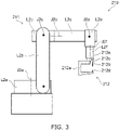
FIG. 3 is a schematic view illustrating a second robot. - [
FIG. 4 ]
FIGS. 4A and 4B are schematic views illustrating operations of a production system according to the embodiment. - [
FIG. 5 ]
FIGS. 5A and 5B are an example of data stored in a memory device. - [
FIG. 6 ]
FIGS. 6A and 6B are flowcharts illustrating processing of the production system according to the embodiment. - [
FIG. 7 ]
FIG. 7 is a perspective view illustrating the internal structure of a detector tip. - [
FIG. 8 ]
FIGS. 8A to 8C are schematic views for describing an inspection method. - [
FIG. 9 ]
FIG. 9 is a flowchart illustrating a specific example of a first task. - [
FIG. 10 ]
FIG. 10 is a drawing for describing a calculation method of the tilt of the detector. - [
FIG. 11 ]
FIG. 11 is an example of an image of detected information. - [
FIG. 12 ]
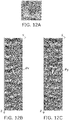
FIGS. 12A to 12C are examples of images of the detected information. - [
FIG. 13 ]
FIG. 13 is a drawing illustrating a configuration example of a processing device and a control device. - Embodiments of the invention will now be described with reference to the drawings.
- The drawings are schematic or conceptual; and the relationships between the thickness and width of portions, proportions of sizes among portions, etc., are not necessarily the same as the actual values. The dimensions and proportions may be illustrated differently among drawings, even when the same portion is illustrated.
- In the specification and drawings, components similar to those already described are marked with the same reference numerals; and a detailed description is omitted as appropriate.
-
FIG. 1 is a schematic view illustrating a production system to which a robot system according to an embodiment is applied. - The
robot system 100 according to the embodiment includes afirst robot 110, acontrol device 120, and aprocessing device 130. Theproduction system 300 includes therobot system 100 and arobot system 200. Therobot system 200 includes asecond robot 210, acontrol device 220, and aprocessing device 230. In the example, theproduction system 300 further includes amemory device 310, ateaching device 320, and amemory device 330. - The
first robot 110 includes afirst manipulator 111 and afirst end effector 112. For example, thefirst end effector 112 is mounted to the distal part of thefirst manipulator 111. Thefirst manipulator 111 is, for example, vertical articulated, horizontal articulated, or parallel link. Thefirst manipulator 111 may be a combination of at least two manipulators selected from vertical articulated, horizontal articulated, and parallel link. Thefirst robot 110 performs a first task corresponding to a function of thefirst end effector 112. - The
control device 120 controls thefirst robot 110 by transmitting a command to thefirst robot 110. For example, thecontrol device 120 controls the posture of thefirst robot 110 by operating a driver included in thefirst manipulator 111. Or, thecontrol device 120 causes thefirst robot 110 to perform a first task by operating thefirst end effector 112. - Here, posture refers to the position and orientation corresponding to degrees of freedom of the robot. For example, the posture of a robot having six degrees of freedom is represented by the positions in three mutually-orthogonal directions (an X-direction, a Y-direction, and a Z-direction) and the angles (rolling, pitting, and yawing) around the directions.
- The
processing device 130 transmits data used in the control of thefirst robot 110 to thecontrol device 120. Or, theprocessing device 130 receives data based on information acquired by thefirst robot 110 from thecontrol device 120. Theprocessing device 130 processes various data as appropriate. - The
second robot 210 includes asecond manipulator 211 and asecond end effector 212. For example, thesecond end effector 212 is mounted to the distal part of thesecond manipulator 211. Thesecond manipulator 211 is, for example, vertical articulated, horizontal articulated, or parallel link. Thesecond manipulator 211 may be a combination of at least two manipulators selected from vertical articulated, horizontal articulated, and parallel link. - The
second robot 210 performs a second task corresponding to a function of thesecond end effector 212. The function of thesecond end effector 212 is different from the function of thefirst end effector 112. Therefore, the second task that is performed by thesecond robot 210 is different from the first task. - The
control device 220 controls thesecond robot 210 by transmitting a command to thesecond robot 210. For example, thecontrol device 220 controls the posture of thesecond robot 210 by operating a driver included in thesecond manipulator 211. Or, thecontrol device 220 operates thesecond end effector 212 to cause thesecond robot 210 to perform the first task. - The
processing device 230 transmits data used in the control of thesecond robot 210 to thecontrol device 220. Or, theprocessing device 230 receives data acquired by thesecond robot 210 from thecontrol device 220. Theprocessing device 230 processes various data as appropriate. - The
memory device 310 stores data related to therobot systems processing device 130 accesses thememory device 310 and acquires data related to the first task, data of the member that is the object of the first task, etc. Similarly, theprocessing device 230 accesses thememory device 310 and acquires data related to the second task, data of the member that is the object of the second task, etc. Theprocessing device 130 stores data related to thefirst robot 110 and the first task transmitted from thecontrol device 120 in thememory device 310. Theprocessing device 230 stores data related to thesecond robot 210 and the second task transmitted from thecontrol device 220 in thememory device 310. - The
first robot 110 and thesecond robot 210 respectively perform the first task and the second task on the same member. For example, thesecond robot 210 performs the second task on a first member. Subsequently, thefirst robot 110 performs the first task on the same first member. - The
memory device 330 stores design data related to the first member. The design data includes, for example, computer-aided design (CAD) data. For example, theteaching device 320 generates the operation program of thesecond robot 210 by referring to the design data. Theteaching device 320 performs a confirmation of the robot operation, a confirmation of interference, etc., by causing the generated operation program to operate in a simulator. - The operation program includes data related to the posture of the
second robot 210. The data shows the posture of a control point of thesecond robot 210 when thesecond robot 210 performs the second task. Hereinafter, the data of the posture of the control point of thesecond robot 210 generated based on the design data is called the design posture data. Theteaching device 320 stores the generated design posture data in thememory device 310. - When the
second robot 210 performs the second task, theprocessing device 230 accesses thememory device 310 and acquires second posture data of the posture of thesecond robot 210. For example, the design posture data is used as the second posture data. Or, the second posture data may be data of a posture taught using thesecond robot 210. - For example, in a workplace in which the second task is actually performed, a worker verifies whether or not problems occur in the workplace when the posture of the
second robot 210 is set based on the design posture data. Specifically, it is confirmed whether or not there is a possibility that thesecond robot 210 may interfere with an article of the workplace or contact a worker when the posture of thesecond robot 210 is set based on the design posture data. When a problem may occur, the worker uses thesecond robot 210 to teach the posture of thesecond robot 210 to eliminate the problem. In such a case, the posture that is taught is stored in thememory device 310 as the second posture data. - The
processing device 130 acquires the second posture data and generates first posture data. The first posture data is of the posture when thefirst robot 110 performs the first task. Theprocessing device 130 stores the first posture data that is generated in thememory device 310. Or, theprocessing device 130 transmits the first posture data that is generated to thecontrol device 120. Thecontrol device 120 sets the posture of thefirst robot 110 based on the first posture data and causes thefirst robot 110 to perform the first task. - The generation of the first posture data may be performed by the
processing device 230. In such a case, the first posture data that is generated is stored in thememory device 310 or transmitted to theprocessing device 130 by theprocessing device 230. - When the first task and the second task are performed on multiple spots of one first member, multiple sets of first posture data and multiple sets of second posture data that correspond to the multiple spots are prepared. The multiple sets of first posture data are generated respectively based on the multiple sets of second posture data. At least a portion of the multiple sets of second posture data is generated based on the design posture data. Other than using the design posture data, at least a portion of the multiple sets of second posture data may be generated based on actual teaching. For example, a portion of the multiple sets of second posture data is generated based on the design posture data; and another portion of the multiple sets of second posture data is generated based on actual teaching.
- The components of the
production system 300 are connected to each other via wired communication, wireless communication, or a network. - Effects of the embodiment will now be described.
- In the
robot system 100 according to the embodiment, thecontrol device 120 receives the first posture data. Then, thecontrol device 120 sets the posture of thefirst robot 110 based on the first posture data and causes thefirst robot 110 to perform the first task. The first posture data is automatically generated by theprocessing device second robot 210 performs the second task. It is therefore unnecessary for a human to teach the posture when thefirst robot 110 performs the first task. According to thecontrol device 120, the time necessary for the human to teach thefirst robot 110 can be reduced. - For example, in a production site, one product is produced by passing through multiple processes. In a production line that uses robots, different types of robots are used in each process. According to the production line, there are cases where one robot in one process performs a task on a specific spot of one member, and then another robot in another process performs a task on the same spot of the same member. By applying the invention according to the embodiment to such a production line, it is unnecessary to teach the posture in the task of the other robot. For example, the time necessary for teaching can be reduced, and the operation of the production line can be faster.
- As a reference example, there is a method in which the first posture data is generated based on the design data. For example, the
teaching device 320 generates the operation program of thefirst robot 110 based on the design data. This method is effective when the second posture data corresponds to the design posture data. By using the first posture data based on the design data, the other robot can perform the task on the same spot as the task performed by the one robot. - However, in practice, as described above, there are also cases where the design posture data is not employed, and the posture is taught in the workplace. In such a case, when the first posture data is generated based on the design posture data, the other robot cannot perform the task on the same spot as the task performed by the one robot. It is therefore favorable to generate the first posture data based on the second posture data. According to the embodiment, even when second posture data that is different from the design posture data is used, the other robot can perform the task on the same spot as the task performed by the one robot.
- Specific examples of the embodiment will now be described.
-
FIG. 2 is a perspective view illustrating the first robot.FIG. 3 is a schematic view illustrating the second robot. - Here, a case is described where the
first manipulator 111 and thesecond manipulator 211 are vertical articulated with six degrees of freedom. - As illustrated in
FIG. 2 , thefirst manipulator 111 includes six joints J1a to J1f and six links L1a to L1f that are alternately linked. The joints J1a to J1f are driven by not-illustrated drivers. Thecontrol device 120 drives the joints J1a to J1f, thereby adjusting the posture of the control point of thefirst robot 110. - As illustrated in
FIG. 3 , thesecond manipulator 211 includes six joints J2a to J2f and the six links L2a to L2f that are alternately linked. The joints J2a to J2f are driven by not-illustrated drivers. Thecontrol device 220 drives the joints J2a to J2f, thereby adjusting the posture of the control point of thesecond robot 210. - The control point is the point of which the posture is controlled by the
control device first robot 110" also is called simply "the posture of thefirst robot 110". Similarly, "the posture of the control point of thesecond robot 210" also is called "the posture of thesecond robot 210". - As one specific example, the
first end effector 112 includes adetector 112a and acoating device 112b as illustrated inFIG. 2 . Thesecond end effector 212 includes a welding device. As illustrated inFIG. 3 , the welding device includes awelding gun 212a, anupper electrode 212b, a raising/loweringpart 212c, alower electrode 212d, and acurrent supply part 212e. - The
second end effector 212 performs spot welding on the first member. In other words, the second task is spot welding. Thefirst end effector 112 transmits an ultrasonic wave toward the spot-welded weld portion and detects a reflected wave of the ultrasonic wave. In other words, the first task acquires information related to the weld portion. -
FIGS. 4A and 4B are schematic views illustrating operations of the production system according to the embodiment. - For example, the first task and the second task are performed on a
first member 10 illustrated inFIG. 4A by therobot systems first member 10 includessteel plates - For example, as illustrated in
FIG. 4A , a transfer device T transfers thefirst member 10 to a position at which thesecond robot 210 is installed. The transfer device T stops at a preset position related to the second task. Thesecond robot 210 performs spot welding of a first part P1 and a second part P2 of thefirst member 10. Specifically, thesecond manipulator 211 operates so that the first part P1 or the second part P2 is positioned between theupper electrode 212b and thelower electrode 212d. The raising/loweringpart 212c operates and moves theupper electrode 212b toward thelower electrode 212d. Thefirst member 10 is clamped by theupper electrode 212b and thelower electrode 212d. Thecurrent supply part 212e intermittently supplies a current between theupper electrode 212b and thelower electrode 212d. Thesteel plates - The posture when the
second robot 210 performs the spot welding is set based on the second posture data. For example, the second posture data includes the coordinates (PX2 , PY2 , and PZ2 ) of the part at which thesecond robot 210 spot-welds and the angles (αJ2a , αJ2b , αJ2c , αJ2d , αJ2e , and αJ2f ) of the joints J2a to J2f. When spot-welding the first part P1, thecontrol device 220 refers to the second posture data of the posture when spot-welding the first part P1. When spot-welding the second part P2, thecontrol device 220 refers to the second posture data of the posture when spot-welding the second part P2. For each spot weld, thecontrol device 220 sets the posture of thesecond robot 210 based on the second posture data that is referred to. - When the spot welding is completed, the transfer device T transfers the
first member 10 to the position at which thefirst robot 110 is installed. The transfer device T stops at a position preset for the first task. As illustrated inFIG. 4B , thefirst robot 110 acquires information related to the first and second parts P1 and P2 of thefirst member 10. Specifically, thefirst manipulator 111 operates so that thecoating device 112b faces the first part P1. Thecoating device 112b coats a couplant onto the first part P1. Then, thefirst manipulator 111 operates so that the tip of thedetector 112a contacts the first part P1. Thedetector 112a transmits an ultrasonic wave that detects a reflected wave of the ultrasonic wave. For example, three-dimensional data of the intensity distribution of the reflected wave is acquired. The state of the first part P1 is reflected in the data. Thefirst robot 110 performs a similar operation on the second part P2 as well. - The posture when the
first robot 110 acquires the data is set based on the first posture data. Similarly to the second posture data, the first posture data includes the coordinates (PX1 , PY1 , and PZ1 ) of the part for which thefirst robot 110 acquires the data and the angles (αJ1a , αJ1b , αJ1c , αJ1d , αJ1e , and αJ1f ) of the joints J1a to J1f. - When the
first end effector 112 includes multiple devices, the first posture data is prepared for each of the devices. For example, when acquiring the information of the first part P1, thecontrol device 120 refers to the first posture data of the posture when coating the couplant onto the first part P1 and the first posture data of the posture when acquiring the information of the first part P1. This is similar when acquiring the information of the second part P2. When acquiring the information of the parts, thecontrol device 120 sets the posture of thefirst robot 110 based on the first posture data that is referred to. - The first posture data is generated using the second posture data. For example, the first posture data is generated by the
processing device 230. Theprocessing device 230 refers to the second posture data, first structure data, and second structure data when generating the first posture data. - The first structure data includes data of the structure of the
first manipulator 111. The first structure data further includes data of the relationship between the posture of thefirst robot 110 and the posture of the distal part of thefirst manipulator 111. The data of the structure of thefirst manipulator 111 shows the lengths (βL1a , βL1b , βL1c , βL1d , βL1e , and βL1f ) of the links L1a to L1f included in thefirst manipulator 111. The distal part of thefirst manipulator 111 corresponds to the part of thefirst manipulator 111 for which the posture is calculated using the angles (αJ1a , αJ1b , αJ1c , αJ1d , αJ1e , and αJ1f ) of the joints J1a to J1f and the lengths (βL1a , βL1b , βL1c , βL1d , βL1e , and βL1f ) of the links L1a to L1f. - For example, the positional relationship is represented by the displacement of the posture of the control point of the
first robot 110 with respect to the posture of the distal part of thefirst manipulator 111. Specifically, the positional relationship is represented by the displacements (DX1 , DY1 , and DZ1 ) of the positions in the X-direction, the Y-direction, and the Z-direction and the displacements (Dθ1 , Dφ1 , and Dψ1 ) of the angles around the directions. - The second structure data includes data of the positional relationship between the control point of the
second robot 210 and the distal part of thesecond manipulator 211. - The second structure data includes data of the structure of the
second manipulator 211. The second structure data further includes data of the relationship between the posture of thesecond robot 210 and the posture of the distal part of thesecond manipulator 211. The data of the structure of thesecond manipulator 211 is of the lengths (βL2a , βL2b , βL2c , βL2d , βL2e , and βL2f ) of links L2a to L2f included in thesecond manipulator 211. The distal part of thesecond manipulator 211 corresponds to the part of thesecond manipulator 211 of which the posture is calculated using the angles (αJ2a , αJ2b , αJ2c , αJ2d , αJ2e , and αJ2f ) of the joints J2a to J2f and the lengths (βL2a , βL2b , βL2c , βL2d , βL2e , and βL2f ) of the links L2a to L2f. - For example, the positional relationship is represented by the displacement of the posture of the distal part of the
second manipulator 211 with respect to the posture of the control point of thesecond robot 210. Specifically, the positional relationship is represented by the displacements (DX2 , DY2 , and DZ2 ) of the positions in the X-direction, the Y-direction, and the Z-direction and the displacements (Dθ2 , Dφ2 , and Dψ2 ) of the angles around the directions. - First, the
processing device 230 uses the second posture data and the second structure data to calculate the posture of thesecond robot 210 when spot-welding a designated part. Then, theprocessing device 230 uses the first structure data and the calculated posture to calculate the posture of the distal part of thefirst manipulator 111 when positioning the tip of thefirst end effector 112 at the part to be spot-welded. Theprocessing device 230 uses the calculated posture of the distal part of thefirst manipulator 111 and the lengths (βL1a , βL1b , βL1c , βL1d , βL1e , and βL1f ) of the links L1a to L1f to calculate the angles (αJ1a , αJ1b , αJ1c , αJ1d , αJ1e , and αJ1f ) of the joints J1a to J1f by an inverse kinematics calculation. Thus, the first posture data is generated. The first posture data includes the angles of the joints J1a to J1f when the information of the spot-welded part is acquired. Theprocessing device 230 stores the generated first posture data in thememory device 310. - The coordinates included in the first posture data and the coordinates included in the second posture data may be included in mutually-different coordinate systems or may be included in the same one coordinate system. A correction that corresponds to the different coordinate systems may be applied as appropriate when generating the coordinates of the second posture data based on the coordinates of the first posture data.
- The calculations described above may be omitted when the following conditions are satisfied. A first condition is that the lengths of the links L1a to L1f of the
first manipulator 111 are respectively equal to the lengths of the links L2a to L2f of thesecond manipulator 211. A second condition is that the positional relationship between thefirst robot 110 and thefirst member 10 in the first task is the same as the positional relationship between thesecond robot 210 and thefirst member 10 in the second task. A third condition is that the relationship between the posture of thefirst robot 110 and the posture of the distal part of thefirst manipulator 111 is the same as the relationship between the posture of thesecond robot 210 and the posture of the distal part of thesecond manipulator 211. When these conditions are satisfied, theprocessing device 230 may generate the second posture data as-is as the first posture data and may store the first posture data in thememory device 310. - When the
first end effector 112 includes multiple devices, the first structure data is prepared for each of the devices. The first structure data of each device is used to generate the first posture data when the task is performed using each device. - The transfer device T includes, for example, at least one of a belt conveyor, a roller conveyor, an automated guided vehicle (AGV), or a raising/lowering device. The transfer device T may include multiple transfer mechanisms. For example, a transfer mechanism that transports the member to the position at which the
first robot 110 is installed and another transfer mechanism that transports the member to the position at which thesecond robot 210 is installed may be included. - The operation of the transfer device T may be controlled by the
processing device processing devices -
FIG. 5 is an example of data stored in the memory device. For example, thememory device 310 stores the tables illustrated inFIGS. 5A and 5B. FIG. 5A illustrates a table (a first table) including data related to the first task.FIG. 5B illustrates a table (a second table) including data related to the second task. - Each table includes the process ID, process name, previous process ID, member ID, member name, robot ID, robot name, coordinate, and joint angle. The coordinate indicates the coordinate of the control point of the robot when performing the process. The joint angle indicates the angles of the joints of the robot when performing the process. In the table illustrated in
FIG. 5A , the combination of one coordinate and one joint angle corresponds to one set of first posture data. In the table illustrated inFIG. 5B , the combination of one coordinate and one joint angle corresponds to one set of second posture data. - The
processing device 230 refers to the first table when generating the first posture data. For each process, theprocessing device 230 extracts the previous process ID and refers to the second table. Theprocessing device 230 searches for the process ID in the second table corresponding to the extracted previous process ID and extracts the second posture data associated with the process ID of the second table. Theprocessing device 230 generates the first posture data based on the extracted second posture data. The generated first posture data is associated with the process ID corresponding to the extracted previous process ID and stored in the first table by theprocessing device 230. - When the
first robot 110 performs the first task, theprocessing device 130 appropriately extracts the first posture data from thememory device 310 and transmits the first posture data to thecontrol device 120. Thecontrol device 120 sets the posture of thefirst robot 110 based on the received first posture data and causes the first task to be performed. -
FIGS. 6A and 6B are flowcharts illustrating processing of the production system according to the embodiment. -
FIG. 6A illustrates processing performed before operating the production line.FIG. 6B illustrates processing performed when operating the production line. - As illustrated in
FIG. 6A , based on the design data, theteaching device 320 generates the design posture data when thesecond robot 210 performs the second task (step S1). The second posture data is generated based on the design posture data (step S2). As described above, the second posture data may be generated based on the design posture data and may be generated separately from the design posture data. - As illustrated in
FIG. 6B , thesecond robot 210 performs the second task in the posture indicated by the second posture data (step S3). Theprocessing device 230 generates the first posture data based on the second posture data (step S4). Thefirst robot 110 performs the first task in the posture indicated by the first posture data (step S5). Step S4 may be performed before operating the production line after step S2. -
FIG. 7 is a perspective view illustrating the internal structure of a detector tip. - Operations of the
robot system 100 will now be described in detail. Here, an example is described in which therobot system 100 is used as an inspection system inspecting a spot-welded weld portion. - A
matrix sensor 401 illustrated inFIG. 7 is located inside thedetector 112a tip. Thematrix sensor 401 includes multipleultrasonic sensors 402. Theultrasonic sensors 402 are, for example, transducers. The multipleultrasonic sensors 402 are arranged along two directions (the X-direction and the Y-direction) that cross each other. In the example, the X-direction and the Y-direction are orthogonal. The X-direction and the Y-direction in which the multipleultrasonic sensors 402 are arranged may or may not correspond to the X-direction and the Y-direction of the coordinate system of the position of the control point. -
FIG. 7 illustrates a state of inspecting thefirst member 10. Thefirst member 10 is made by spot-welding asteel plate 11 and asteel plate 12 at aweld portion 13. A solidifiedportion 14 is formed at theweld portion 13 by a portion of thesteel plate 11 and a portion of thesteel plate 12 melting, mixing, and solidifying. Each of theultrasonic sensors 402 transmits an ultrasonic wave US toward thefirst member 10 coated with acouplant 15 and detects (receives) a reflected wave RW from thefirst member 10. - In a more specific example as illustrated in
FIG. 7 , oneultrasonic sensor 402 transmits the ultrasonic wave US toward theweld portion 13. A portion of the ultrasonic wave US is reflected by the upper or lower surface of thefirst member 10, etc. Each of the multipleultrasonic sensors 402 detects the reflected wave RW. Theultrasonic sensors 402 sequentially transmit the ultrasonic wave US; and each reflected wave RW is detected by the multipleultrasonic sensors 402. - Each of the
ultrasonic sensors 402 transmits a signal (a current) toward thecontrol device 120 when detecting the reflected wave. The intensity of the signal corresponds to the intensity of the reflected wave. Thecontrol device 120 transmits data of the received signal intensity to theprocessing device 130. Theprocessing device 130 inspects theweld portion 13 based on the received data. -
FIG. 8 is schematic views for describing an inspection method. - As illustrated in
FIG. 8A , a portion of the ultrasonic wave US is reflected by anupper surface 10a of thesteel plate 11 or anupper surface 10b of theweld portion 13. Another portion of the ultrasonic wave US enters thefirst member 10 and is reflected by alower surface 10c of thesteel plate 11 or alower surface 10d of theweld portion 13. - The Z-direction positions of the
upper surface 10a, theupper surface 10b, thelower surface 10c, and thelower surface 10d are different from each other. In other words, the distances in the Z-direction between theultrasonic sensor 402 and these surfaces are different from each other. The peak of the intensity of the reflected wave is detected when theultrasonic sensor 402 receives the reflected wave from these surfaces. Which surface reflected the ultrasonic wave US can be verified by calculating the time until each peak is detected after transmitting the ultrasonic wave US. -
FIGS. 8B and 8C are graphs illustrating the relationship between the time after transmitting the ultrasonic wave US and the intensity of the reflected wave RW. Here, the intensity of the reflected wave RW is illustrated as an absolute value. The graph ofFIG. 8B illustrates the reception result of the reflected wave RW from theupper surface 10a and thelower surface 10c of thesteel plate 11. The graph ofFIG. 8C illustrates the reception result of the reflected wave RW from theupper surface 10b and thelower surface 10d of theweld portion 13. - In the graph of
FIG. 8B , a peak Pe1 occurring first is based on the reflected wave RW from theupper surface 10a. A peak Pe2 occurring second is based on the reflected wave RW from thelower surface 10c. The times at which the peak Pe1 and the peak Pe2 are detected correspond respectively to the Z-direction positions of theupper surface 10a and thelower surface 10c of thesteel plate 11. A time difference TD1 between the time at which the peak Pe1 is detected and the time at which the peak Pe2 is detected corresponds to a distance Di1 in the Z-direction between theupper surface 10a and thelower surface 10c. - Similarly, in the graph of
FIG. 8C , a peak Pe3 occurring first is based on the reflected wave RW from theupper surface 10b. A peak Pe4 occurring second is based on the reflected wave RW from thelower surface 10d. The times at which the peak Pe3 and the peak Pe4 are detected correspond respectively to the Z-direction positions of theupper surface 10b and thelower surface 10d of theweld portion 13. A time difference TD2 between the time at which the peak Pe3 is detected and the time at which the peak Pe4 is detected correspond to a distance Di2 in the Z-direction between theupper surface 10b and thelower surface 10d. - The
processing device 130 inspects whether or not multiple points at theweld portion 13 vicinity are welded based on the time difference of the adjacent peaks. There are cases where theupper surface 10b and thelower surface 10d of theweld portion 13 are tilted with respect to theupper surface 10a of thesteel plate 11. This is due to theweld portion 13 including the solidifiedportion 14, shape deformation in the welding process, etc. In such a case, it is desirable for the ultrasonic waves US to be transmitted along a direction that is, on average, perpendicular to theupper surface 10b or thelower surface 10d. Thereby, the ultrasonic wave can be reflected more intensely at theupper surface 10b and thelower surface 10d, and the accuracy of the inspection can be increased. -
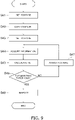
FIG. 9 is a flowchart illustrating a specific example of the first task. - First, the
control device 120 refers to the first posture data of the posture of thefirst robot 110 when the couplant is coated using thecoating device 112b. Thecontrol device 120 sets the posture of thefirst robot 110 based on the first posture data (step S41). Thecontrol device 120 causes the couplant to be coated onto thefirst member 10 from thecoating device 112b (step S42). Thecontrol device 120 refers to the first posture data of the posture of thefirst robot 110 when the information is acquired using thedetector 112a. Thecontrol device 120 sets the posture of thefirst robot 110 based on the first posture data (step S43). Thecontrol device 120 uses thedetector 112a to acquire information of the spot-welded weld portion (step S44). - The
control device 120 transmits the acquired information to theprocessing device 130. Theprocessing device 130 processes the information and calculates the tilt of thedetector 112a with respect to the first member 10 (step S45). Theprocessing device 130 determines whether or not the tilt is less than a prescribed threshold (step S46). When the tilt is greater than the threshold, thecontrol device 120 adjusts the posture of thefirst robot 110 to reduce the tilt (step S47). After the adjustment of the posture, step S44 is re-performed. - When the tilt is less than the threshold, the
processing device 130 inspects the weld portion by using the information acquired in step S44 directly before (step S48). Specifically, it is determined whether or not thefirst member 10 is appropriately welded at the weld portion. For example, theprocessing device 130 stores the inspection result in thememory device 310. - One specific example of a method for calculating the tilt will now be described.
-
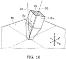
FIG. 10 is a drawing for describing the calculation method of the tilt of the detector. -
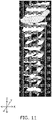
FIGS. 11 and12 are examples of images of the detected information. -
FIG. 11 is three-dimensional volume data depicted based on the detection result of the reflected wave.FIG. 12A illustrates the surface of theweld portion 13 in the volume data illustrated inFIG. 11 .FIG. 12B illustrates a Y-Z cross section at theweld portion 13 vicinity in the volume data illustrated inFIG. 11 .FIG. 12C illustrates an X-Z cross section at theweld portion 13 vicinity in the volume data illustrated inFIG. 11 . InFIGS. 12B and 12C , the upper side is the surface of theweld portion 13; and the data in the depth direction is shown downward. Parts of high luminance are parts of high ultrasonic wave reflection intensity. The ultrasonic wave is intensely reflected by the bottom surface of theweld portion 13, the surfaces between the unjoined members, etc. - The tilt of the
detector 112a corresponds to the angle between a direction D1 perpendicular to theweld portion 13 and a direction D2 of thedetector 112a illustrated inFIG. 10 . This angle is represented by an angle θx around the X-direction and an angle θy around the Y-direction. The direction D2 is perpendicular to the arrangement direction of theultrasonic sensors 402. - As illustrated in
FIG. 12B , the angle θx is calculated based on the detection result in the Y-Z cross section. As illustrated inFIG. 12C , the angle θy is calculated based on the detection result in the X-Z cross section. Theprocessing device 130 calculates the average of the three-dimensional luminance gradient of each cross section as the angles θx and θy. Theprocessing device 130 stores the calculated angles θx and θy in thememory device 310 as the tilt of thedetector 112a. -
FIG. 13 is a drawing illustrating a configuration example of the processing device and the control device. - The
control device 120, theprocessing device 130, thecontrol device 220, and theprocessing device 230 each include, for example, a central processing unit (CPU) 501,main memory 502,nonvolatile memory 503, an I/O interface 504, and abus 505 as illustrated inFIG. 13 . - The
bus 505 connects theCPU 501, themain memory 502, thenonvolatile memory 503, and the I/O interface 504 to each other. - The
main memory 502 is accessible more quickly than thenonvolatile memory 503. Themain memory 502 includes, for example, random access memory (RAM). Thenonvolatile memory 503 is used as a storage region of various data. Thenonvolatile memory 503 includes, for example, read only memory (ROM), flash memory, an optical disk, a magnetic disk, a detachable memory device, or a combination of such memory. The I/O interface 504 is an interface device for connecting to other devices. - Programs necessary for the processing of the
control device 120, theprocessing device 130, thecontrol device 220, or theprocessing device 230 are stored in thenonvolatile memory 503. For example, firmware programs and robot programs for causing thecontrol device first robot 110 or thesecond robot 210 are stored. The operation procedures of the robots are described in the robot programs. For example, in thecontrol device CPU 501 loads the firmware program from thenonvolatile memory 503 into themain memory 502. TheCPU 501 executes the robot program based on the loaded firmware program. TheCPU 501 interprets the robot program and calculates the drive command for the driver of the first orsecond robot O interface 504. - The
control device 120, theprocessing device 130, thecontrol device 220, and theprocessing device 230 each may have the configuration illustrated inFIG. 13 , or one device that has the configuration illustrated inFIG. 13 may function as at least two selected from thecontrol device 120, theprocessing device 130, thecontrol device 220, and theprocessing device 230. For example, one control device may function as thecontrol devices processing devices - The configuration illustrated in
FIG. 13 is applicable to theteaching device 320 as well. - The time necessary for a human to teach the first robot can be reduced by using the control method performed by the
control device 120, therobot system 100, the inspection system, theproduction system 300, or thecontrol device 120 described above. Similar effects can be obtained by using a program that causes the control device of the robot system to perform the control method described above. - The processing of the various data described above may be recorded, as a program that can be executed by a computer, in a magnetic disk (a flexible disk, a hard disk, etc.), an optical disk (CD-ROM, CD-R, CD-RW, DVD-ROM, DVD±R, DVD±RW, etc.), semiconductor memory, or another recording medium.
- For example, the data that is recorded in the recording medium can be read by the computer (or an embedded system). The recording format (the storage format) of the recording medium is arbitrary. For example, the computer reads the program from the recording medium and causes a CPU to execute the instructions recited in the program based on the program. In the computer, the acquisition (or the reading) of the program may be performed via a network.
- While certain embodiments of the inventions have been illustrated, these embodiments have been presented by way of example only, and are not intended to limit the scope of the inventions. These novel embodiments may be embodied in a variety of other forms; and various omissions, substitutions, modifications, etc., can be made without departing from the spirit of the inventions. These embodiments and their modifications are within the scope and spirit of the inventions, and are within the scope of the inventions described in the claims and their equivalents. The embodiments described above can be implemented in combination with each other.
Claims (12)
- A control device (120),the control device (120) receiving first posture data of a posture of a first robot (110), the first robot (110) including a first manipulator (111) and a first end effector (112),the control device (120) setting the posture of the first robot (110) based on the first posture data and causing the first robot (110) to perform a first task on a first member,the first posture data being generated based on second posture data of a posture when a second robot (210) performs a second task on the first member,the second robot (210) including a second manipulator (211) and a second end effector (212).
- The control device (120) according to claim 1, whereinthe control device (120) receives a plurality of sets of the first posture data,the control device (110) sequentially sets the posture of the first robot (110) based on the plurality of sets of first posture data, andthe control device (120) causes the first robot (110) to perform the first task at each of the postures.
- The control device (120) according to claim 2, whereinthe plurality of sets of first posture data is generated respectively based on a plurality of sets of the second posture data,a portion of the plurality of sets of second posture data is generated based on design posture data generated from design data of the first member, andan other portion of the plurality of sets of second posture data is generated based on teaching to the second robot (210).
- The control device (120) according to claim 1, whereinthe first posture data is generated using the second posture data, first structure data, and second structure data,the first structure data is of a relationship between a structure of the first manipulator (111), a posture of a distal part of the first manipulator (111) and the posture of the first robot (110), andthe second structure data is of a relationship between a structure of the second manipulator (211), a posture of a distal part of the second manipulator (211), and the posture of the second robot (210).
- The control device (120) according to any one of claims 1 to 4, whereinthe first end effector (112) includes a detector (112a), an ultrasonic sensor (402) is included in the detector (112a),the second end effector (212) includes a welding device performing spot welding, andin the first task, the first robot (110) is caused to use the detector (112a) to acquire information of a weld portion (13) that was spot-welded.
- An inspection system, comprising:the control device (120) according to claim 5; anda processing device (130),the information including a reflected wave intensity of an ultrasonic wave from the weld portion (13),the processing device (130) using the information to perform an inspection of the weld portion (13) of a calculation of a tilt of the detector (112a) with respect to the weld portion (13).
- The inspection system according to claim 6, further comprising:
the first robot (110). - A control method, comprising:receiving first posture data of a posture of a first robot (110), the first robot (110) including a first manipulator (111) and a first end effector (112); andsetting the posture of the first robot (110) based on the first posture data and causing the first robot (110) to perform a first task on a first member,the first posture data being generated based on second posture data of a posture when a second robot (210) performs a second task on the first member,the second robot (210) including a second manipulator (211) and a second end effector (212).
- The control method according to claim 8, whereinthe first end effector (112) includes a detector (112a),an ultrasonic sensor (402) is included in the detector (112a),the second end effector (212) includes a welding device performing spot welding, andin the first task, the first robot (110) is caused to use the detector (112a) to acquire information of a weld portion (13) that was spot-welded.
- A program causing a computer to function as a control device (120),the control device (120) receiving first posture data of a posture of a first robot (110),the first robot (110) including a first manipulator (111) and a first end effector (112),the control device (120) setting the posture of the first robot (110) based on the first posture data and causing the first robot (110) to perform a first task on a first member,the first posture data being generated based on second posture data of a posture when a second robot (210) performs a second task on the first member,the second robot (210) including a second manipulator (211) and a second end effector (212).
- The program according to claim 10, whereinthe first end effector (112) includes a detector (112a),an ultrasonic sensor (402) is included in the detector (112a),the second end effector (212) includes a welding device performing spot welding, andin the first task, the control device (120) causes the first robot (110) to use the detector (112a) to acquire information of a weld portion (13) that was spot-welded.
- A storage medium,
the storage medium storing the program according to claim 10 or 11.
Applications Claiming Priority (2)
| Application Number | Priority Date | Filing Date | Title |
|---|---|---|---|
| JP2020047852A JP7620391B2 (en) | 2020-03-18 | 2020-03-18 | CONTROL DEVICE, INSPECTION SYSTEM, CONTROL METHOD, PROGRAM, AND STORAGE MEDIUM |
| PCT/JP2021/005498 WO2021186981A1 (en) | 2020-03-18 | 2021-02-15 | Control device, inspection system, control method, program, and storage medium |
Publications (2)
| Publication Number | Publication Date |
|---|---|
| EP4122658A1 true EP4122658A1 (en) | 2023-01-25 |
| EP4122658A4 EP4122658A4 (en) | 2024-02-14 |
Family
ID=77768084
Family Applications (1)
| Application Number | Title | Priority Date | Filing Date |
|---|---|---|---|
| EP21771279.3A Pending EP4122658A4 (en) | 2020-03-18 | 2021-02-15 | CONTROL DEVICE, INSPECTION SYSTEM, CONTROL METHOD, PROGRAM AND STORAGE MEDIUM |
Country Status (5)
| Country | Link |
|---|---|
| US (1) | US20230001582A1 (en) |
| EP (1) | EP4122658A4 (en) |
| JP (1) | JP7620391B2 (en) |
| CN (1) | CN115315340A (en) |
| WO (1) | WO2021186981A1 (en) |
Families Citing this family (1)
| Publication number | Priority date | Publication date | Assignee | Title |
|---|---|---|---|---|
| JP7332821B1 (en) * | 2021-11-19 | 2023-08-23 | 株式会社日立製作所 | WELD INSPECTION METHOD AND INSPECTION DEVICE |
Family Cites Families (15)
| Publication number | Priority date | Publication date | Assignee | Title |
|---|---|---|---|---|
| JPH0643917A (en) * | 1992-07-23 | 1994-02-18 | Toyota Motor Corp | Robot group control method |
| JPH06265529A (en) * | 1993-03-15 | 1994-09-22 | Hitachi Ltd | Method and apparatus for evaluating spot-welded part |
| US5495410A (en) * | 1994-08-12 | 1996-02-27 | Minnesota Mining And Manufacturing Company | Lead-through robot programming system |
| JP3218553B2 (en) * | 1995-03-28 | 2001-10-15 | 日本電信電話株式会社 | Robot system control method and device |
| US20020169586A1 (en) * | 2001-03-20 | 2002-11-14 | Rankin James Stewart | Automated CAD guided sensor planning process |
| JP2005334945A (en) * | 2004-05-27 | 2005-12-08 | Fanuc Ltd | Spot welding equipment |
| JP2006236031A (en) * | 2005-02-25 | 2006-09-07 | Seiko Epson Corp | Robot trajectory control method and apparatus, and program for robot trajectory control method |
| JP5179981B2 (en) * | 2008-07-14 | 2013-04-10 | 日野自動車株式会社 | Automatic welding / inspection method and automatic welding / inspection system |
| JP5715809B2 (en) * | 2010-03-29 | 2015-05-13 | 株式会社ダイヘン | Robot work program creation method, robot work program creation device, and robot control system |
| JP5850958B2 (en) * | 2014-01-24 | 2016-02-03 | ファナック株式会社 | Robot programming device for creating a robot program for imaging a workpiece |
| JP6661925B2 (en) * | 2015-09-07 | 2020-03-11 | セイコーエプソン株式会社 | Control devices, robots and robot systems |
| JP6570600B2 (en) | 2017-11-15 | 2019-09-04 | 株式会社東芝 | Inspection system, control device, angle adjustment method, program, and storage medium |
| JP2019171506A (en) * | 2018-03-28 | 2019-10-10 | Ntn株式会社 | Complex working device using link operation device |
| US10821603B2 (en) * | 2018-09-05 | 2020-11-03 | The Boeing Company | Methods and apparatus for robot control |
| JP7214589B2 (en) * | 2019-07-30 | 2023-01-30 | 株式会社東芝 | Inspection system, angle adjustment method, program, and storage medium |
-
2020
- 2020-03-18 JP JP2020047852A patent/JP7620391B2/en active Active
-
2021
- 2021-02-15 CN CN202180021121.2A patent/CN115315340A/en active Pending
- 2021-02-15 WO PCT/JP2021/005498 patent/WO2021186981A1/en not_active Ceased
- 2021-02-15 EP EP21771279.3A patent/EP4122658A4/en active Pending
-
2022
- 2022-09-13 US US17/931,759 patent/US20230001582A1/en active Pending
Also Published As
| Publication number | Publication date |
|---|---|
| US20230001582A1 (en) | 2023-01-05 |
| CN115315340A (en) | 2022-11-08 |
| WO2021186981A1 (en) | 2021-09-23 |
| EP4122658A4 (en) | 2024-02-14 |
| JP2021146437A (en) | 2021-09-27 |
| JP7620391B2 (en) | 2025-01-23 |
Similar Documents
| Publication | Publication Date | Title |
|---|---|---|
| US8606402B2 (en) | Manipulator and control method thereof | |
| US12330308B2 (en) | Robot system, parallel link mechanism, control method, control device, and storage medium | |
| JP6841206B2 (en) | Robot system and robot control method | |
| KR100311663B1 (en) | Apparatus and method for tracking the appearance of an object using a spare shaft | |
| US8948904B2 (en) | Work picking system | |
| US20120277898A1 (en) | Processing system and processing method | |
| US20080027580A1 (en) | Robot programming method and apparatus with both vision and force | |
| US20230256615A1 (en) | Robot device controller for controlling position of robot | |
| JP2025511612A (en) | Autonomous Assembly Robot | |
| CN114714029A (en) | Automatic arc welding method and device for aluminium alloy | |
| CN104227722A (en) | Robot system and robot control method | |
| JP2010142910A (en) | Robot system | |
| JP2008279524A (en) | Multiple robot collision detection method and robot apparatus | |
| CN107214692A (en) | The automatic calibration method of robot system | |
| CN108858182B (en) | Robot control device, robot control method, and robot system | |
| Debus et al. | Cooperative human and machine perception in teleoperated assembly | |
| US11247288B2 (en) | Welding position detection device, welding position detection method, and welding robot system | |
| US20230001582A1 (en) | Control device, inspection system, control method, and storage medium | |
| KR102904385B1 (en) | Method and apparatus for generating moving path of robot, robot system, and program | |
| CN111318782B (en) | Method for calibrating robot welding gun and laser weld tracking sensor of marine pipe welding machine | |
| JP7105223B2 (en) | robot system | |
| US20210146542A1 (en) | Control method for robot system | |
| US20240109196A1 (en) | Workstation and Operating Method Therefore | |
| JP6367702B2 (en) | Positioning system and welding system | |
| CN109986238B (en) | Robot linear flexible operation vision fuzzy profiling control method |
Legal Events
| Date | Code | Title | Description |
|---|---|---|---|
| STAA | Information on the status of an ep patent application or granted ep patent |
Free format text: STATUS: THE INTERNATIONAL PUBLICATION HAS BEEN MADE |
|
| PUAI | Public reference made under article 153(3) epc to a published international application that has entered the european phase |
Free format text: ORIGINAL CODE: 0009012 |
|
| STAA | Information on the status of an ep patent application or granted ep patent |
Free format text: STATUS: REQUEST FOR EXAMINATION WAS MADE |
|
| 17P | Request for examination filed |
Effective date: 20220913 |
|
| AK | Designated contracting states |
Kind code of ref document: A1 Designated state(s): AL AT BE BG CH CY CZ DE DK EE ES FI FR GB GR HR HU IE IS IT LI LT LU LV MC MK MT NL NO PL PT RO RS SE SI SK SM TR |
|
| DAV | Request for validation of the european patent (deleted) | ||
| DAX | Request for extension of the european patent (deleted) | ||
| A4 | Supplementary search report drawn up and despatched |
Effective date: 20240115 |
|
| RIC1 | Information provided on ipc code assigned before grant |
Ipc: G05B 19/42 20060101ALI20240109BHEP Ipc: G01N 29/26 20060101ALI20240109BHEP Ipc: B25J 9/22 20060101AFI20240109BHEP |
|
| STAA | Information on the status of an ep patent application or granted ep patent |
Free format text: STATUS: EXAMINATION IS IN PROGRESS |
|
| 17Q | First examination report despatched |
Effective date: 20250728 |