EP4122632A1 - Joined body and method for manufacturing joined body - Google Patents
Joined body and method for manufacturing joined body Download PDFInfo
- Publication number
- EP4122632A1 EP4122632A1 EP21772247.9A EP21772247A EP4122632A1 EP 4122632 A1 EP4122632 A1 EP 4122632A1 EP 21772247 A EP21772247 A EP 21772247A EP 4122632 A1 EP4122632 A1 EP 4122632A1
- Authority
- EP
- European Patent Office
- Prior art keywords
- metal member
- protruded
- recessed portion
- bonded body
- bonded
- Prior art date
- Legal status (The legal status is an assumption and is not a legal conclusion. Google has not performed a legal analysis and makes no representation as to the accuracy of the status listed.)
- Withdrawn
Links
- 238000000034 method Methods 0.000 title claims description 21
- 238000004519 manufacturing process Methods 0.000 title claims description 16
- 229910052751 metal Inorganic materials 0.000 claims abstract description 222
- 239000002184 metal Substances 0.000 claims abstract description 222
- 239000000463 material Substances 0.000 claims abstract description 35
- 239000011347 resin Substances 0.000 claims abstract description 29
- 229920005989 resin Polymers 0.000 claims abstract description 29
- 238000010438 heat treatment Methods 0.000 claims description 16
- 235000019589 hardness Nutrition 0.000 description 27
- 229910052782 aluminium Inorganic materials 0.000 description 8
- XAGFODPZIPBFFR-UHFFFAOYSA-N aluminium Chemical compound [Al] XAGFODPZIPBFFR-UHFFFAOYSA-N 0.000 description 8
- 238000012360 testing method Methods 0.000 description 7
- RYGMFSIKBFXOCR-UHFFFAOYSA-N Copper Chemical compound [Cu] RYGMFSIKBFXOCR-UHFFFAOYSA-N 0.000 description 6
- 229910052802 copper Inorganic materials 0.000 description 6
- 239000010949 copper Substances 0.000 description 6
- 150000002739 metals Chemical class 0.000 description 6
- 229910000737 Duralumin Inorganic materials 0.000 description 4
- 238000011156 evaluation Methods 0.000 description 4
- 230000008595 infiltration Effects 0.000 description 4
- 238000001764 infiltration Methods 0.000 description 4
- 229910000838 Al alloy Inorganic materials 0.000 description 3
- 238000000137 annealing Methods 0.000 description 3
- 230000007797 corrosion Effects 0.000 description 3
- 238000005260 corrosion Methods 0.000 description 3
- 238000009792 diffusion process Methods 0.000 description 3
- 229910000765 intermetallic Inorganic materials 0.000 description 3
- 229920006358 Fluon Polymers 0.000 description 2
- 239000000853 adhesive Substances 0.000 description 2
- 230000001070 adhesive effect Effects 0.000 description 2
- 230000000694 effects Effects 0.000 description 2
- 230000002349 favourable effect Effects 0.000 description 2
- 238000012545 processing Methods 0.000 description 2
- 239000010935 stainless steel Substances 0.000 description 2
- 229910001220 stainless steel Inorganic materials 0.000 description 2
- 239000004952 Polyamide Substances 0.000 description 1
- 239000004642 Polyimide Substances 0.000 description 1
- 229910000831 Steel Inorganic materials 0.000 description 1
- 238000007545 Vickers hardness test Methods 0.000 description 1
- HCHKCACWOHOZIP-UHFFFAOYSA-N Zinc Chemical compound [Zn] HCHKCACWOHOZIP-UHFFFAOYSA-N 0.000 description 1
- 238000005452 bending Methods 0.000 description 1
- 238000012790 confirmation Methods 0.000 description 1
- 230000006866 deterioration Effects 0.000 description 1
- 238000002474 experimental method Methods 0.000 description 1
- 238000005259 measurement Methods 0.000 description 1
- -1 or the like) Inorganic materials 0.000 description 1
- 229920002647 polyamide Polymers 0.000 description 1
- 229920001721 polyimide Polymers 0.000 description 1
- 238000003825 pressing Methods 0.000 description 1
- 239000010959 steel Substances 0.000 description 1
- 239000011701 zinc Substances 0.000 description 1
- 229910052725 zinc Inorganic materials 0.000 description 1
Images
Classifications
-
- B—PERFORMING OPERATIONS; TRANSPORTING
- B23—MACHINE TOOLS; METAL-WORKING NOT OTHERWISE PROVIDED FOR
- B23K—SOLDERING OR UNSOLDERING; WELDING; CLADDING OR PLATING BY SOLDERING OR WELDING; CUTTING BY APPLYING HEAT LOCALLY, e.g. FLAME CUTTING; WORKING BY LASER BEAM
- B23K20/00—Non-electric welding by applying impact or other pressure, with or without the application of heat, e.g. cladding or plating
- B23K20/02—Non-electric welding by applying impact or other pressure, with or without the application of heat, e.g. cladding or plating by means of a press ; Diffusion bonding
-
- B—PERFORMING OPERATIONS; TRANSPORTING
- B32—LAYERED PRODUCTS
- B32B—LAYERED PRODUCTS, i.e. PRODUCTS BUILT-UP OF STRATA OF FLAT OR NON-FLAT, e.g. CELLULAR OR HONEYCOMB, FORM
- B32B3/00—Layered products comprising a layer with external or internal discontinuities or unevennesses, or a layer of non-planar shape; Layered products comprising a layer having particular features of form
- B32B3/26—Layered products comprising a layer with external or internal discontinuities or unevennesses, or a layer of non-planar shape; Layered products comprising a layer having particular features of form characterised by a particular shape of the outline of the cross-section of a continuous layer; characterised by a layer with cavities or internal voids ; characterised by an apertured layer
- B32B3/30—Layered products comprising a layer with external or internal discontinuities or unevennesses, or a layer of non-planar shape; Layered products comprising a layer having particular features of form characterised by a particular shape of the outline of the cross-section of a continuous layer; characterised by a layer with cavities or internal voids ; characterised by an apertured layer characterised by a layer formed with recesses or projections, e.g. hollows, grooves, protuberances, ribs
-
- B—PERFORMING OPERATIONS; TRANSPORTING
- B23—MACHINE TOOLS; METAL-WORKING NOT OTHERWISE PROVIDED FOR
- B23K—SOLDERING OR UNSOLDERING; WELDING; CLADDING OR PLATING BY SOLDERING OR WELDING; CUTTING BY APPLYING HEAT LOCALLY, e.g. FLAME CUTTING; WORKING BY LASER BEAM
- B23K20/00—Non-electric welding by applying impact or other pressure, with or without the application of heat, e.g. cladding or plating
- B23K20/002—Non-electric welding by applying impact or other pressure, with or without the application of heat, e.g. cladding or plating specially adapted for particular articles or work
-
- B—PERFORMING OPERATIONS; TRANSPORTING
- B23—MACHINE TOOLS; METAL-WORKING NOT OTHERWISE PROVIDED FOR
- B23K—SOLDERING OR UNSOLDERING; WELDING; CLADDING OR PLATING BY SOLDERING OR WELDING; CUTTING BY APPLYING HEAT LOCALLY, e.g. FLAME CUTTING; WORKING BY LASER BEAM
- B23K20/00—Non-electric welding by applying impact or other pressure, with or without the application of heat, e.g. cladding or plating
- B23K20/22—Non-electric welding by applying impact or other pressure, with or without the application of heat, e.g. cladding or plating taking account of the properties of the materials to be welded
-
- B—PERFORMING OPERATIONS; TRANSPORTING
- B23—MACHINE TOOLS; METAL-WORKING NOT OTHERWISE PROVIDED FOR
- B23K—SOLDERING OR UNSOLDERING; WELDING; CLADDING OR PLATING BY SOLDERING OR WELDING; CUTTING BY APPLYING HEAT LOCALLY, e.g. FLAME CUTTING; WORKING BY LASER BEAM
- B23K20/00—Non-electric welding by applying impact or other pressure, with or without the application of heat, e.g. cladding or plating
- B23K20/22—Non-electric welding by applying impact or other pressure, with or without the application of heat, e.g. cladding or plating taking account of the properties of the materials to be welded
- B23K20/233—Non-electric welding by applying impact or other pressure, with or without the application of heat, e.g. cladding or plating taking account of the properties of the materials to be welded without ferrous layer
-
- B—PERFORMING OPERATIONS; TRANSPORTING
- B23—MACHINE TOOLS; METAL-WORKING NOT OTHERWISE PROVIDED FOR
- B23K—SOLDERING OR UNSOLDERING; WELDING; CLADDING OR PLATING BY SOLDERING OR WELDING; CUTTING BY APPLYING HEAT LOCALLY, e.g. FLAME CUTTING; WORKING BY LASER BEAM
- B23K20/00—Non-electric welding by applying impact or other pressure, with or without the application of heat, e.g. cladding or plating
- B23K20/24—Preliminary treatment
-
- B—PERFORMING OPERATIONS; TRANSPORTING
- B32—LAYERED PRODUCTS
- B32B—LAYERED PRODUCTS, i.e. PRODUCTS BUILT-UP OF STRATA OF FLAT OR NON-FLAT, e.g. CELLULAR OR HONEYCOMB, FORM
- B32B15/00—Layered products comprising a layer of metal
- B32B15/04—Layered products comprising a layer of metal comprising metal as the main or only constituent of a layer, which is next to another layer of the same or of a different material
- B32B15/043—Layered products comprising a layer of metal comprising metal as the main or only constituent of a layer, which is next to another layer of the same or of a different material of metal
-
- B—PERFORMING OPERATIONS; TRANSPORTING
- B32—LAYERED PRODUCTS
- B32B—LAYERED PRODUCTS, i.e. PRODUCTS BUILT-UP OF STRATA OF FLAT OR NON-FLAT, e.g. CELLULAR OR HONEYCOMB, FORM
- B32B7/00—Layered products characterised by the relation between layers; Layered products characterised by the relative orientation of features between layers, or by the relative values of a measurable parameter between layers, i.e. products comprising layers having different physical, chemical or physicochemical properties; Layered products characterised by the interconnection of layers
- B32B7/02—Physical, chemical or physicochemical properties
- B32B7/022—Mechanical properties
-
- B—PERFORMING OPERATIONS; TRANSPORTING
- B23—MACHINE TOOLS; METAL-WORKING NOT OTHERWISE PROVIDED FOR
- B23K—SOLDERING OR UNSOLDERING; WELDING; CLADDING OR PLATING BY SOLDERING OR WELDING; CUTTING BY APPLYING HEAT LOCALLY, e.g. FLAME CUTTING; WORKING BY LASER BEAM
- B23K2103/00—Materials to be soldered, welded or cut
- B23K2103/08—Non-ferrous metals or alloys
- B23K2103/10—Aluminium or alloys thereof
-
- B—PERFORMING OPERATIONS; TRANSPORTING
- B23—MACHINE TOOLS; METAL-WORKING NOT OTHERWISE PROVIDED FOR
- B23K—SOLDERING OR UNSOLDERING; WELDING; CLADDING OR PLATING BY SOLDERING OR WELDING; CUTTING BY APPLYING HEAT LOCALLY, e.g. FLAME CUTTING; WORKING BY LASER BEAM
- B23K2103/00—Materials to be soldered, welded or cut
- B23K2103/08—Non-ferrous metals or alloys
- B23K2103/12—Copper or alloys thereof
-
- B—PERFORMING OPERATIONS; TRANSPORTING
- B23—MACHINE TOOLS; METAL-WORKING NOT OTHERWISE PROVIDED FOR
- B23K—SOLDERING OR UNSOLDERING; WELDING; CLADDING OR PLATING BY SOLDERING OR WELDING; CUTTING BY APPLYING HEAT LOCALLY, e.g. FLAME CUTTING; WORKING BY LASER BEAM
- B23K2103/00—Materials to be soldered, welded or cut
- B23K2103/18—Dissimilar materials
-
- B—PERFORMING OPERATIONS; TRANSPORTING
- B32—LAYERED PRODUCTS
- B32B—LAYERED PRODUCTS, i.e. PRODUCTS BUILT-UP OF STRATA OF FLAT OR NON-FLAT, e.g. CELLULAR OR HONEYCOMB, FORM
- B32B15/00—Layered products comprising a layer of metal
- B32B15/04—Layered products comprising a layer of metal comprising metal as the main or only constituent of a layer, which is next to another layer of the same or of a different material
- B32B15/08—Layered products comprising a layer of metal comprising metal as the main or only constituent of a layer, which is next to another layer of the same or of a different material of synthetic resin
- B32B15/088—Layered products comprising a layer of metal comprising metal as the main or only constituent of a layer, which is next to another layer of the same or of a different material of synthetic resin comprising polyamides
-
- B—PERFORMING OPERATIONS; TRANSPORTING
- B32—LAYERED PRODUCTS
- B32B—LAYERED PRODUCTS, i.e. PRODUCTS BUILT-UP OF STRATA OF FLAT OR NON-FLAT, e.g. CELLULAR OR HONEYCOMB, FORM
- B32B15/00—Layered products comprising a layer of metal
- B32B15/20—Layered products comprising a layer of metal comprising aluminium or copper
-
- B—PERFORMING OPERATIONS; TRANSPORTING
- B32—LAYERED PRODUCTS
- B32B—LAYERED PRODUCTS, i.e. PRODUCTS BUILT-UP OF STRATA OF FLAT OR NON-FLAT, e.g. CELLULAR OR HONEYCOMB, FORM
- B32B2307/00—Properties of the layers or laminate
- B32B2307/20—Properties of the layers or laminate having particular electrical or magnetic properties, e.g. piezoelectric
- B32B2307/202—Conductive
-
- B—PERFORMING OPERATIONS; TRANSPORTING
- B32—LAYERED PRODUCTS
- B32B—LAYERED PRODUCTS, i.e. PRODUCTS BUILT-UP OF STRATA OF FLAT OR NON-FLAT, e.g. CELLULAR OR HONEYCOMB, FORM
- B32B2307/00—Properties of the layers or laminate
- B32B2307/50—Properties of the layers or laminate having particular mechanical properties
- B32B2307/536—Hardness
-
- B—PERFORMING OPERATIONS; TRANSPORTING
- B32—LAYERED PRODUCTS
- B32B—LAYERED PRODUCTS, i.e. PRODUCTS BUILT-UP OF STRATA OF FLAT OR NON-FLAT, e.g. CELLULAR OR HONEYCOMB, FORM
- B32B2307/00—Properties of the layers or laminate
- B32B2307/50—Properties of the layers or laminate having particular mechanical properties
- B32B2307/542—Shear strength
-
- B—PERFORMING OPERATIONS; TRANSPORTING
- B32—LAYERED PRODUCTS
- B32B—LAYERED PRODUCTS, i.e. PRODUCTS BUILT-UP OF STRATA OF FLAT OR NON-FLAT, e.g. CELLULAR OR HONEYCOMB, FORM
- B32B27/00—Layered products comprising a layer of synthetic resin
- B32B27/28—Layered products comprising a layer of synthetic resin comprising synthetic resins not wholly covered by any one of the sub-groups B32B27/30 - B32B27/42
- B32B27/281—Layered products comprising a layer of synthetic resin comprising synthetic resins not wholly covered by any one of the sub-groups B32B27/30 - B32B27/42 comprising polyimides
-
- B—PERFORMING OPERATIONS; TRANSPORTING
- B32—LAYERED PRODUCTS
- B32B—LAYERED PRODUCTS, i.e. PRODUCTS BUILT-UP OF STRATA OF FLAT OR NON-FLAT, e.g. CELLULAR OR HONEYCOMB, FORM
- B32B27/00—Layered products comprising a layer of synthetic resin
- B32B27/34—Layered products comprising a layer of synthetic resin comprising polyamides
-
- B—PERFORMING OPERATIONS; TRANSPORTING
- B32—LAYERED PRODUCTS
- B32B—LAYERED PRODUCTS, i.e. PRODUCTS BUILT-UP OF STRATA OF FLAT OR NON-FLAT, e.g. CELLULAR OR HONEYCOMB, FORM
- B32B7/00—Layered products characterised by the relation between layers; Layered products characterised by the relative orientation of features between layers, or by the relative values of a measurable parameter between layers, i.e. products comprising layers having different physical, chemical or physicochemical properties; Layered products characterised by the interconnection of layers
- B32B7/04—Interconnection of layers
- B32B7/12—Interconnection of layers using interposed adhesives or interposed materials with bonding properties
Definitions
- the present invention relates to a bonded body in which a first metal member and a second metal member, which are made of metals different from each other, are bonded to each other, and a method for manufacturing the bonded body.
- diffusion bonding may be applied, for example, as disclosed in Patent Document 1.
- the bonding is carried out under relatively high temperature conditions, and there is concern that an intermetallic compound may be generated at the bonding interface, which causes brittle fracture.
- diffusion since diffusion is used, there is a problem that applicable metal combinations are limited.
- Patent Document 1 proposes a method for bonding different kinds of metal plates, in which a first metal plate and a second metal plate are overlapped and bonded by utilizing frictional heat.
- the first metal plate and the second metal plate are softened and deformed by pressing a processing tool having a bending part while rotating it, and these are bonded to each other to form a structure.
- Patent Document 2 proposes a bonded product in which a zinc-based plated steel sheet and an aluminum alloy plate are bonded by an adhesive.
- the first metal plate and the second metal plate are deformed with a processing tool; however, there is concern that a gap may be generated between the first metal plate and the second metal plate. In a case where moisture or the like infiltrates into this gap, deterioration such as corrosion is caused.
- An object of the prevent invention is to provide a bonded body in which metal members made of metals different from each other are reliably bonded to each other, which has excellent electrical conductivity and thermal conductivity, and can suppress the infiltration of moisture and the like into the gap between the metal members, and a method for manufacturing a bonded body.
- the bonded body of the present invention is characterized by being a bonded body in which a first metal member is bonded to a second metal member, where the first metal member is formed of a material having a hardness higher than that of the second metal member, the bonded body has a structure in which the second metal member is inserted into a protruded and recessed portion formed on a bonding surface of the first metal member, the bonded body has a region in which the first metal member is in direct contact with the second metal member, and a gap between the first metal member and the second metal member is filled with a resin material.
- the first metal member is formed of a material having a hardness higher than that of the second metal member, and the bonded body has a structure in which the second metal member is inserted into a protruded and recessed portion formed on a bonding surface of the first metal member, the first metal member is reliably bonded to the second metal member.
- the bonding interface does not become a major obstacle to electrical conductivity and thermal conductivity, whereby the bonded body has excellent electrical conductivity and thermal conductivity.
- the gap between the first metal member and the second metal member is filled with a resin material, moisture or the like does not infiltrate into the gap, whereby corrosion or the like can be prevented.
- the method for manufacturing a bonded body of the present invention is characterized by being a method for manufacturing a bonded body in which a first metal member is bonded to a second metal member, the method including:
- a protruded and recessed portion is formed on a bonding surface of the first metal member formed of a material having a hardness higher than that of the second metal member, and the second metal member is stacked on this bonding surface, via a resin material, and pressurized in a stacking direction.
- the second metal member is deformed and inserted into the protruded and recessed portion of the first metal member, and the gap between the first metal member and the second metal member is filled with a resin material, whereby it is possible to manufacture a bonded body that has excellent electrical conductivity and thermal conductivity and can suppress the infiltration of moisture and the like into the gap between the metal members.
- a bonded body in which metal members made of metals different from each other are reliably bonded to each other, which has excellent electrical conductivity and thermal conductivity, and can suppress the infiltration of moisture and the like into the gap between the metal members, and a method for manufacturing a bonded body.
- a bonded body 1 has a structure in which a first metal member 10 and a second metal member 20, which are formed of metals different from each other, are bonded to each other.
- the first metal member 10 is formed of a material having a hardness higher than a hardness of the second metal member 20.
- the ratio H1/H2 of the hardness H1 of the first metal member 10 to the hardness H2 of the second metal member 20 is preferably in a range of 1.3 or more, and more preferably in a range of 1.5 or more.
- the H1/H2 is preferably in a range of 1.3 or more. In a case where the first metal member 10 is formed of a metal that has not been subjected to an annealing treatment or the like, the H1/H2 is preferably in a range of 1.5 or more.
- the bonded body 1 having an H1/H2 of 1.5 or more obtained in a bonding step S03 may be subjected to an annealing treatment to obtain the bonded body 1 having an H1/H2 of 1.3 or more, or the bonded body 1 having an H1/H2 of 1.3 or more may be obtained by being formed of a metal that is annealed by the bonding temperature.
- the upper limit of the H1/H2 is preferably 110.
- the first metal member 10 is formed of a copper plate made of oxygen-free copper (hardness: 55 Hv)
- the second metal member 20 is formed of an aluminum plate made of 4N aluminum having a purity of 99.99% by mass or more (hardness: 29 Hv).
- the hardness (Hv) indicated in the present embodiment is the Vickers hardness obtained according to a Vickers hardness test.
- the first metal member 10 is not particularly limited as long as the relationship between the hardness H1 of the first metal member 10 and the hardness H2 of the second metal member 20 is within the above range; however, it is favorable to use a member made of oxygen-free copper, an aluminum alloy (A6063, duralumin, or the like), or stainless steel (SUS).
- the second metal member 20 is not particularly limited as long as the relationship between the hardness H1 of the first metal member 10 and the hardness H2 of the second metal member 20 is within the above range; however, it is favorable to use a member made of 4N aluminum having a purity of 99.99% by mass or more or 1000 series aluminum (pure aluminum having a purity of 99.00% by mass or more).
- the bonded body has a structure in which at the bonding interface between the first metal member 10 and the second metal member 20, as shown in Fig. 1(b) , the second metal member 20 is inserted into a protruded and recessed portion 12 formed on the bonding surface of the first metal member 10, and the bonded body has a region in which the first metal member 10 is in direct contact with the second metal member 20.
- the bonded body has a structure in which the second metal member 20 having low hardness is deformed and inserted into the protruded and recessed portion 12 formed on the bonding surface of the first metal member 10.
- the protruded and recessed portion 12 is composed of a plurality of grooves that extend in parallel in one direction, and the cross section orthogonal to the extending direction has a substantially triangular shape. At the side surface portion of this groove, the first metal member 10 is in direct contact with the second metal member 20.
- the height from the bottom part to the apex part of the protruded and recessed portion 12 is within a range of 0.1 mm or more and 5 mm or less.
- the spacing between grooves is set within a range of 0.1 mm or more and 5 mm or less.
- the region in which the first metal member 10 is in direct contact with the second metal member 20 (that is, the region in which the second metal member 20 is inserted into the protruded and recessed portion 12) is set in a range of 50% or more of the height from the bottom part to the apex part of the protruded and recessed portion 12.
- the bottom part of the recessed portion of the protruded and recessed portion 12 formed on the bonding surface of the first metal member 10 is filled with a resin material 30.
- the resin material 30 with which the first metal member 10 is filled is preferably a resin having adhesiveness, where the main component of the resin material is preferably those having thermoplasticity and heat resistance, for example, fluororesin, polyimide, and polyamide.
- the resin material 30 with which the recessed portion of the protruded and recessed portion 12 is filled is formed of fluororesin.
- the protruded and recessed portion 12 is formed on the bonding surface of the first metal member 10.
- the method for forming the protruded and recessed portion 12 is not particularly limited, and various existing methods can be applied.
- the bonding surface of the first metal member 10 is subjected to knurling to form the protruded and recessed portion 12 composed of a plurality of grooves that extend in parallel in one direction.
- the second metal member 20 is stacked on the bonding surface of the first metal member 10 on which the protruded and recessed portion 12 is formed, via a resin material.
- a resin sheet 31 using a fluororesin Fluon + EA-2000 manufactured by AGC Inc. is disposed as the resin material.
- the thickness of the resin sheet 31 is preferably in a range of 1 ⁇ m or more and 100 ⁇ m or less.
- the first metal member 10 and the second metal member 20 stacked by via the resin sheet 31 are heated and bonded while being pressurized in the stacking direction.
- the second metal member 20 having low hardness is deformed and inserted into the protruded and recessed portion 12 of the first metal member 10. Further, the resin sheet 31 is cut due to pressurization and inserted into the protruded and recessed portion 12 together with the second metal member 20, whereby the gap between the first metal member 10 and the second metal member 20 is filled with the resin material 30.
- the pressurizing pressure in the bonding step S03 is preferably set in a range of 10 MPa or more and 100 MPa or less.
- the second metal member 20 can be sufficiently inserted into the protruded and recessed portion 12 of the first metal member 10, and thus the bonding strength can be ensured.
- the pressurizing pressure is set to 60 MPa or less, it is possible to suppress that the second metal member 20 is deformed more than necessary, and thus it is possible to maintain the shape of the bonded body 1.
- the lower limit of the pressurizing pressure in the bonding step S03 is preferably set to 10 MPa or more, and more preferably 30 MPa or more. Further, the upper limit of the pressurizing pressure in the bonding step S03 is preferably set to 100 MPa or less, and more preferably 60 MPa or less.
- the heating temperature in the bonding step S03 is preferably set in a range of 100°C or higher and 450°C or lower.
- the heating temperature is set to 300°C or higher, the second metal member 20 can be softened to be sufficiently inserted into the protruded and recessed portion 12 of the first metal member 10, and thus the bonding strength can be ensured.
- the heating temperature is set to 450°C or lower, it is possible to suppress the generation of an intermetallic compound between the first metal member 10 and the second metal member 20.
- the lower limit of the heating temperature in the bonding step S03 is preferably set to 100°C or higher, and more preferably 300°C or higher. Further, the upper limit of the heating temperature in the bonding step S03 is preferably set to 450°C or lower, and more preferably 400°C or lower.
- the holding time at the heating temperature in the bonding step S03 is preferably set in a range of 1 minute or more and 60 minutes or less.
- the second metal member 20 can be softened to be sufficiently inserted into the protruded and recessed portion 12 of the first metal member 10, and thus the bonding strength can be ensured.
- the holding time at the heating temperature is set to 60 minutes or less, it is possible to suppress the generation of an intermetallic compound between the first metal member 10 and the second metal member 20.
- the lower limit of the holding time at the heating temperature in the bonding step S03 is preferably set to 1 minute or more, and more preferably 5 minutes or more. Further, the lower limit of the holding time at the heating temperature in the bonding step S03 is preferably set to 60 minute or less, and more preferably 30 minutes or less.
- the bonded body 1 according to the present embodiment is manufactured according to the protruded and recessed portion forming step S01, the stacking step S02, and the bonding step S03.
- the first metal member 10 is formed of a material having a hardness higher than that of the second metal member 20, and the bonded body has a structure in which the second metal member 20 is inserted into a protruded and recessed portion 12 formed on a bonding surface of the first metal member 10, the first metal member 10 is reliably bonded to the second metal member 20.
- the bonding interface does not become a major obstacle to electrical conductivity and thermal conductivity, whereby the bonded body has excellent electrical conductivity and thermal conductivity.
- the height from the bottom part to the apex part of the protruded and recessed portion 12 is set within a range of 0.1 mm or more and 5 mm or less, the region in which the first metal member 10 is in direct contact with the second metal member 20 (that is, the region in which the second metal member 20 is inserted into the protruded and recessed portion 12) has sufficient bonding strength and is particularly excellent in electrical conductivity and thermal conductivity in a case where it is set in a range of 50% or more of the height from the bottom part to the apex part of the protruded and recessed portion 12.
- the gap between the first metal member 10 and the second metal member 20 is filled with the resin material 30, moisture or the like does not infiltrate into the gap, whereby corrosion or the like can be prevented.
- the resin material 30 in a case where the resin material 30 is formed of fluororesin, the resin material 30 itself has adhesiveness, and thus the bonding strength between the first metal member 10 and the second metal member 20 is can be further improved.
- the second metal member 20 is deformed and inserted into the protruded and recessed portion 12 of the first metal member 10, and the gap between the first metal member 10 and the second metal member 20 is filled with the resin material 30. This makes it possible to manufacture the bonded body 1 according to the present embodiment.
- the present embodiment is not limited thereto, and the first metal member and the second metal member may be combined with another metal as long as they differ in hardness from each other.
- the protruded and recessed portion is composed of a plurality of grooves that extend in parallel in one direction
- the present embodiment is not limited to this shape, and a protruded and recessed portion having another shape may be good.
- the second metal member was stacked on the bonding surface of the first metal member, on which the protruded and recessed portion had been formed, via a fluororesin Fluon + EA-2000 film manufactured by AGC Inc. having a thickness of 12 ⁇ m. At this time, the arrangement position was adjusted so that the first metal member was arranged at the center of the second metal member.
- the stacked first metal member and second metal member were pressurized in the stacking direction and heated to bond the first metal member to the second metal member.
- Table 1 shows the pressurizing pressure, the heating temperature, and the holding time at the heating temperature in the bonding step.
- the hardness H1 of the oxygen-free copper was 55 Hv
- the hardness H1 of the aluminum alloy (A6063) was 60 Hv
- the hardness H1 of duralumin was 170 Hv
- the hardness H1 of stainless steel (SUS) was 200 Hv
- the hardness H2 of the 4N aluminum used as the second metal member was 29 Hv.
- the ratio H1/H2 was calculated from these hardnesses and is shown in Table 1.
- the shear strength, conductivity, and bonded state of the obtained bonded body were evaluated as follows. The evaluation results are shown in Table 1.
- the second metal member was fixed horizontally, in a state where the first metal member faced up, and it was pushed at a position of 50 ⁇ m above the first metal member horizontally from the side with a shear tool, and then the strength at the time when the first metal member and the second metal member were peeled off from each other was measured.
- a tester (TY720, manufactured by Yokogawa Test & Measurement Corporation) was applied between the first metal member and the second metal member, and then a case of less than 500 ⁇ in the conduction check mode was evaluated as "A”, and a case where conduction was not confirmed was evaluated as "B".
- the shear strength was sufficiently high in all of the bonded bodies and the bonded bodies are reliably bonded.
- the evaluation of the conductivity is "A”
- the first metal member is in direct contact with the second metal member, and the conductivity is excellent.
- the region in which the first metal member is in direct contact with the second metal member is in a range of 50% or more of the height from the bottom part to the apex part of the protruded and recessed portion, and the bonded state is excellent.
Landscapes
- Engineering & Computer Science (AREA)
- Mechanical Engineering (AREA)
- Pressure Welding/Diffusion-Bonding (AREA)
Abstract
Description
- The present invention relates to a bonded body in which a first metal member and a second metal member, which are made of metals different from each other, are bonded to each other, and a method for manufacturing the bonded body.
- Priority is claimed on
Japanese Patent Application No. 2020-047794, filed March 18, 2020 - In the related art, in a case of bonding members made of metals different from each other, diffusion bonding may be applied, for example, as disclosed in Patent Document 1. In a case where such diffusion bonding is carried out, the bonding is carried out under relatively high temperature conditions, and there is concern that an intermetallic compound may be generated at the bonding interface, which causes brittle fracture. In addition, since diffusion is used, there is a problem that applicable metal combinations are limited.
- Here, for example, Patent Document 1 proposes a method for bonding different kinds of metal plates, in which a first metal plate and a second metal plate are overlapped and bonded by utilizing frictional heat. In the method of Patent Document 1, the first metal plate and the second metal plate are softened and deformed by pressing a processing tool having a bending part while rotating it, and these are bonded to each other to form a structure.
- Further,
Patent Document 2 proposes a bonded product in which a zinc-based plated steel sheet and an aluminum alloy plate are bonded by an adhesive. -
- [Patent Document 1]
Japanese Patent No. 5854451 - [Patent Document 2]
Japanese Patent No. 6393592 - By the way, in the method disclosed in Patent Document 1, the first metal plate and the second metal plate are deformed with a processing tool; however, there is concern that a gap may be generated between the first metal plate and the second metal plate. In a case where moisture or the like infiltrates into this gap, deterioration such as corrosion is caused.
- Further, in the method disclosed in
Patent Document 2, an adhesive is interposed between the metal members, and there is concern that the conductivity and the thermal conductivity are greatly deteriorated. - The present invention has been made in consideration of the above-described circumstances, An object of the prevent invention is to provide a bonded body in which metal members made of metals different from each other are reliably bonded to each other, which has excellent electrical conductivity and thermal conductivity, and can suppress the infiltration of moisture and the like into the gap between the metal members, and a method for manufacturing a bonded body.
- In order to solve the above problems, the bonded body of the present invention is characterized by being a bonded body in which a first metal member is bonded to a second metal member, where the first metal member is formed of a material having a hardness higher than that of the second metal member, the bonded body has a structure in which the second metal member is inserted into a protruded and recessed portion formed on a bonding surface of the first metal member, the bonded body has a region in which the first metal member is in direct contact with the second metal member, and a gap between the first metal member and the second metal member is filled with a resin material.
- According to the bonded body of the present invention, since the first metal member is formed of a material having a hardness higher than that of the second metal member, and the bonded body has a structure in which the second metal member is inserted into a protruded and recessed portion formed on a bonding surface of the first metal member, the first metal member is reliably bonded to the second metal member.
- In addition, since the bonded body has a region in which the first metal member is in direct contact with the second metal member, the bonding interface does not become a major obstacle to electrical conductivity and thermal conductivity, whereby the bonded body has excellent electrical conductivity and thermal conductivity.
- Further, since the gap between the first metal member and the second metal member is filled with a resin material, moisture or the like does not infiltrate into the gap, whereby corrosion or the like can be prevented.
- The method for manufacturing a bonded body of the present invention is characterized by being a method for manufacturing a bonded body in which a first metal member is bonded to a second metal member, the method including:
- a protruded and recessed portion forming step of forming a protruded and recessed portion on a bonding surface of the first metal member formed of a material having a hardness higher than that of the second metal member;
- a stacking step of stacking the second metal member on the bonding surface of the first metal member on which the protruded and recessed portion is formed, via a resin material; and
- a bonding step of heating and bonding the first metal member and the second metal member while pressurizing the first metal member and the second metal member in a stacking direction,
- in which in the bonding step, the second metal member is inserted into the protruded and recessed portion of the first metal member, and
- a gap between the first metal member and the second metal member is filled with the resin material.
- According to the method for manufacturing a bonded body having this configuration, a protruded and recessed portion is formed on a bonding surface of the first metal member formed of a material having a hardness higher than that of the second metal member, and the second metal member is stacked on this bonding surface, via a resin material, and pressurized in a stacking direction. As a result, the second metal member is deformed and inserted into the protruded and recessed portion of the first metal member, and the gap between the first metal member and the second metal member is filled with a resin material, whereby it is possible to manufacture a bonded body that has excellent electrical conductivity and thermal conductivity and can suppress the infiltration of moisture and the like into the gap between the metal members.
- According to the present invention, it is possible to provide a bonded body in which metal members made of metals different from each other are reliably bonded to each other, which has excellent electrical conductivity and thermal conductivity, and can suppress the infiltration of moisture and the like into the gap between the metal members, and a method for manufacturing a bonded body.
-
-
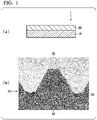
Fig. 1 is a schematic explanatory view of a bonded body according to an embodiment of the present invention.Fig. 1(a) is a schematic cross-sectional view, andFig. 1(b) is an enlarged explanatory view of a bonding interface. -
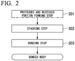
Fig. 2 is a flow chart of a method for manufacturing a bonded body according to an embodiment of the present invention. -
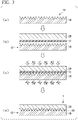
Fig. 3 is a schematic explanatory view of the method for manufacturing a bonded body according to the embodiment of the present invention.Fig. 3(a) shows a protruded and recessed portion forming step,Fig. 3(b) shows a stacking step,Fig. 3(c) shows a bonding step, andFig. 3(d) shows an obtained bonded body. - Hereinafter, embodiments of the present invention will be described with reference to the accompanying drawings. Each embodiment to be described below is specifically described for a better understanding of the gist of the invention and does not limit the present invention unless otherwise specified. In addition, in the drawings used in the following description, for convenience, a portion that is a main part may be enlarged in some cases in order to make the features of the present invention easy to understand, and the dimensional ratio or the like of each component is not always the same as the actual one.
- As shown in
Fig. 1 , a bonded body 1 according to the present embodiment has a structure in which afirst metal member 10 and asecond metal member 20, which are formed of metals different from each other, are bonded to each other. - Here, the
first metal member 10 is formed of a material having a hardness higher than a hardness of thesecond metal member 20. The ratio H1/H2 of the hardness H1 of thefirst metal member 10 to the hardness H2 of thesecond metal member 20 is preferably in a range of 1.3 or more, and more preferably in a range of 1.5 or more. - More specifically, in a case where the
first metal member 10 is formed of a metal that has been subjected to an annealing treatment, the H1/H2 is preferably in a range of 1.3 or more. In a case where thefirst metal member 10 is formed of a metal that has not been subjected to an annealing treatment or the like, the H1/H2 is preferably in a range of 1.5 or more. - In the manufacturing method described later, the bonded body 1 having an H1/H2 of 1.5 or more obtained in a bonding step S03 may be subjected to an annealing treatment to obtain the bonded body 1 having an H1/H2 of 1.3 or more, or the bonded body 1 having an H1/H2 of 1.3 or more may be obtained by being formed of a metal that is annealed by the bonding temperature.
- Further, the upper limit of the H1/H2 is preferably 110.
- In the present embodiment, the
first metal member 10 is formed of a copper plate made of oxygen-free copper (hardness: 55 Hv), and thesecond metal member 20 is formed of an aluminum plate made of 4N aluminum having a purity of 99.99% by mass or more (hardness: 29 Hv). - The hardness (Hv) indicated in the present embodiment is the Vickers hardness obtained according to a Vickers hardness test.
- The
first metal member 10 is not particularly limited as long as the relationship between the hardness H1 of thefirst metal member 10 and the hardness H2 of thesecond metal member 20 is within the above range; however, it is favorable to use a member made of oxygen-free copper, an aluminum alloy (A6063, duralumin, or the like), or stainless steel (SUS). - The
second metal member 20 is not particularly limited as long as the relationship between the hardness H1 of thefirst metal member 10 and the hardness H2 of thesecond metal member 20 is within the above range; however, it is favorable to use a member made of 4N aluminum having a purity of 99.99% by mass or more or 1000 series aluminum (pure aluminum having a purity of 99.00% by mass or more). - The bonded body has a structure in which at the bonding interface between the
first metal member 10 and thesecond metal member 20, as shown inFig. 1(b) , thesecond metal member 20 is inserted into a protruded andrecessed portion 12 formed on the bonding surface of thefirst metal member 10, and the bonded body has a region in which thefirst metal member 10 is in direct contact with thesecond metal member 20. - That is, the bonded body has a structure in which the
second metal member 20 having low hardness is deformed and inserted into the protruded and recessedportion 12 formed on the bonding surface of thefirst metal member 10. - Here, in the present embodiment, the protruded and
recessed portion 12 is composed of a plurality of grooves that extend in parallel in one direction, and the cross section orthogonal to the extending direction has a substantially triangular shape. At the side surface portion of this groove, thefirst metal member 10 is in direct contact with thesecond metal member 20. - The height from the bottom part to the apex part of the protruded and
recessed portion 12 is within a range of 0.1 mm or more and 5 mm or less. In addition, the spacing between grooves is set within a range of 0.1 mm or more and 5 mm or less. - Further, the region in which the
first metal member 10 is in direct contact with the second metal member 20 (that is, the region in which thesecond metal member 20 is inserted into the protruded and recessed portion 12) is set in a range of 50% or more of the height from the bottom part to the apex part of the protruded and recessedportion 12. - In addition, the bottom part of the recessed portion of the protruded and
recessed portion 12 formed on the bonding surface of thefirst metal member 10 is filled with aresin material 30. - Here, the
resin material 30 with which thefirst metal member 10 is filled is preferably a resin having adhesiveness, where the main component of the resin material is preferably those having thermoplasticity and heat resistance, for example, fluororesin, polyimide, and polyamide. In the present embodiment, theresin material 30 with which the recessed portion of the protruded and recessedportion 12 is filled is formed of fluororesin. - Hereinafter, a method for manufacturing a bonded body 1 according to the present embodiment having the above-described configuration will be described with reference to
Fig. 2 andFig. 3 . - First, as shown in
Fig. 3(a) , the protruded and recessedportion 12 is formed on the bonding surface of thefirst metal member 10. The method for forming the protruded and recessedportion 12 is not particularly limited, and various existing methods can be applied. - In the present embodiment, the bonding surface of the
first metal member 10 is subjected to knurling to form the protruded and recessedportion 12 composed of a plurality of grooves that extend in parallel in one direction. - Next, as shown in
Fig. 3(b) , thesecond metal member 20 is stacked on the bonding surface of thefirst metal member 10 on which the protruded and recessedportion 12 is formed, via a resin material. - Here, in the present embodiment, a
resin sheet 31 using a fluororesin Fluon + EA-2000 manufactured by AGC Inc. is disposed as the resin material. The thickness of theresin sheet 31 is preferably in a range of 1 µm or more and 100 µm or less. - Next, as shown in
Fig. 3(c) , thefirst metal member 10 and thesecond metal member 20 stacked by via theresin sheet 31 are heated and bonded while being pressurized in the stacking direction. - As a result, the
second metal member 20 having low hardness is deformed and inserted into the protruded and recessedportion 12 of thefirst metal member 10. Further, theresin sheet 31 is cut due to pressurization and inserted into the protruded and recessedportion 12 together with thesecond metal member 20, whereby the gap between thefirst metal member 10 and thesecond metal member 20 is filled with theresin material 30. - Here, the pressurizing pressure in the bonding step S03 is preferably set in a range of 10 MPa or more and 100 MPa or less.
- In a case where the pressurizing pressure is set to 20 MPa or more, the
second metal member 20 can be sufficiently inserted into the protruded and recessedportion 12 of thefirst metal member 10, and thus the bonding strength can be ensured. On the other hand, in a case where the pressurizing pressure is set to 60 MPa or less, it is possible to suppress that thesecond metal member 20 is deformed more than necessary, and thus it is possible to maintain the shape of the bonded body 1. - The lower limit of the pressurizing pressure in the bonding step S03 is preferably set to 10 MPa or more, and more preferably 30 MPa or more. Further, the upper limit of the pressurizing pressure in the bonding step S03 is preferably set to 100 MPa or less, and more preferably 60 MPa or less.
- Further, the heating temperature in the bonding step S03 is preferably set in a range of 100°C or higher and 450°C or lower.
- In a case where the heating temperature is set to 300°C or higher, the
second metal member 20 can be softened to be sufficiently inserted into the protruded and recessedportion 12 of thefirst metal member 10, and thus the bonding strength can be ensured. On the other hand, in a case where the heating temperature is set to 450°C or lower, it is possible to suppress the generation of an intermetallic compound between thefirst metal member 10 and thesecond metal member 20. - The lower limit of the heating temperature in the bonding step S03 is preferably set to 100°C or higher, and more preferably 300°C or higher. Further, the upper limit of the heating temperature in the bonding step S03 is preferably set to 450°C or lower, and more preferably 400°C or lower.
- Further, the holding time at the heating temperature in the bonding step S03 is preferably set in a range of 1 minute or more and 60 minutes or less.
- In a case where the holding time at the heating temperature is set to 1 minute or more, the
second metal member 20 can be softened to be sufficiently inserted into the protruded and recessedportion 12 of thefirst metal member 10, and thus the bonding strength can be ensured. On the other hand, in a case where the holding time at the heating temperature is set to 60 minutes or less, it is possible to suppress the generation of an intermetallic compound between thefirst metal member 10 and thesecond metal member 20. - The lower limit of the holding time at the heating temperature in the bonding step S03 is preferably set to 1 minute or more, and more preferably 5 minutes or more. Further, the lower limit of the holding time at the heating temperature in the bonding step S03 is preferably set to 60 minute or less, and more preferably 30 minutes or less.
- As described above, the bonded body 1 according to the present embodiment is manufactured according to the protruded and recessed portion forming step S01, the stacking step S02, and the bonding step S03.
- According to the bonded body 1 of the present embodiment having such a configuration as described above, since the
first metal member 10 is formed of a material having a hardness higher than that of thesecond metal member 20, and the bonded body has a structure in which thesecond metal member 20 is inserted into a protruded and recessedportion 12 formed on a bonding surface of thefirst metal member 10, thefirst metal member 10 is reliably bonded to thesecond metal member 20. - In addition, since the bonded body has a region in which the
first metal member 10 is in direct contact with thesecond metal member 20, the bonding interface does not become a major obstacle to electrical conductivity and thermal conductivity, whereby the bonded body has excellent electrical conductivity and thermal conductivity. - In the present embodiment, the height from the bottom part to the apex part of the protruded and recessed
portion 12 is set within a range of 0.1 mm or more and 5 mm or less, the region in which thefirst metal member 10 is in direct contact with the second metal member 20 (that is, the region in which thesecond metal member 20 is inserted into the protruded and recessed portion 12) has sufficient bonding strength and is particularly excellent in electrical conductivity and thermal conductivity in a case where it is set in a range of 50% or more of the height from the bottom part to the apex part of the protruded and recessedportion 12. - Further, since the gap between the
first metal member 10 and thesecond metal member 20 is filled with theresin material 30, moisture or the like does not infiltrate into the gap, whereby corrosion or the like can be prevented. - In the present embodiment, in a case where the
resin material 30 is formed of fluororesin, theresin material 30 itself has adhesiveness, and thus the bonding strength between thefirst metal member 10 and thesecond metal member 20 is can be further improved. - Further, according to the method for manufacturing the bonded body 1 according to the present embodiment, a protruded and recessed portion forming step S01 of forming the protruded and recessed
portion 12 on a bonding surface of thefirst metal member 10 made of a material having a hardness higher than that of thesecond metal member 20, a stacking step S02 of stacking thesecond metal member 20 on the bonding surface of thefirst metal member 10 by via theresin sheet 31, and a bonding step S03 of heating and bonding thefirst metal member 10 and thesecond metal member 20 while pressurizing them in a stacking direction are provided. As a result, thesecond metal member 20 is deformed and inserted into the protruded and recessedportion 12 of thefirst metal member 10, and the gap between thefirst metal member 10 and thesecond metal member 20 is filled with theresin material 30. This makes it possible to manufacture the bonded body 1 according to the present embodiment. - Although the embodiment of the present invention has been described above, the present invention is not limited thereto and can be appropriately modified without departing from the technical idea of the invention.
- For example, in the present embodiment, the description has been made by assuming that the first metal member is a copper plate and the second metal member is an aluminum plate. However, the present embodiment is not limited thereto, and the first metal member and the second metal member may be combined with another metal as long as they differ in hardness from each other.
- In addition, although the description has been made assuming that a fluororesin is used as the resin material, the present embodiment is not limited thereto, and another resin material may be used.
- Further, in the present embodiment, although the description has been made by assuming that the protruded and recessed portion is composed of a plurality of grooves that extend in parallel in one direction, the present embodiment is not limited to this shape, and a protruded and recessed portion having another shape may be good.
- Hereinafter, the results of the confirmation experiment carried out to confirm the effect of the present invention will be described.
- First, as the first metal member (10 mm □), a metal having the material and thickness shown in Table 1 was prepared.
- As the second metal member, 4N aluminum (30 mm □, thickness:1.6 mm) was prepared.
- Then, the bonding surface of the first metal member was subjected to knurling to form a protruded and recessed portion having the shape shown in Table 1.
- The second metal member was stacked on the bonding surface of the first metal member, on which the protruded and recessed portion had been formed, via a fluororesin Fluon + EA-2000 film manufactured by AGC Inc. having a thickness of 12 µm. At this time, the arrangement position was adjusted so that the first metal member was arranged at the center of the second metal member.
- The stacked first metal member and second metal member were pressurized in the stacking direction and heated to bond the first metal member to the second metal member. Table 1 shows the pressurizing pressure, the heating temperature, and the holding time at the heating temperature in the bonding step.
- Regarding those used as the first metal member, the hardness H1 of the oxygen-free copper was 55 Hv, the hardness H1 of the aluminum alloy (A6063) was 60 Hv, the hardness H1 of duralumin was 170 Hv, and the hardness H1 of stainless steel (SUS) was 200 Hv. The hardness H2 of the 4N aluminum used as the second metal member was 29 Hv. The ratio H1/H2 was calculated from these hardnesses and is shown in Table 1.
- The shear strength, conductivity, and bonded state of the obtained bonded body were evaluated as follows. The evaluation results are shown in Table 1.
- Using a shear strength evaluation tester, the second metal member was fixed horizontally, in a state where the first metal member faced up, and it was pushed at a position of 50 µm above the first metal member horizontally from the side with a shear tool, and then the strength at the time when the first metal member and the second metal member were peeled off from each other was measured.
- A tester (TY720, manufactured by Yokogawa Test & Measurement Corporation) was applied between the first metal member and the second metal member, and then a case of less than 500 Ω in the conduction check mode was evaluated as "A", and a case where conduction was not confirmed was evaluated as "B".
- Five points in a region in which the first metal member was in direct contact with the second metal member in the cross section of the obtained bonded body were observed using a laser microscope (VK X-200, manufactured by KEYENCE Corporation). At each observation point, the proportion of a region in which the first metal member was in direct contact with the second metal member with respect to the height from the bottom part to the apex part of the protruded and recessed portion was calculated, and then a case where the average value thereof was 50% or more was evaluated as "A", and a case where it was less than 50% was evaluated as "B".
[Table 1] First metal member Ratio Protruded and recessed portion Bonding condition Evaluation Material Thickness (mm) H1/H2 Shape Depth (mm) Pitch (mm) Pressurization load (MPa) Heating temperature (°C) Holding time (min) Shear strength (MPa) Conductivity Bonded state Test No. 1 Oxygen-free copper 10.0 1.9 V-shaped groove 0.6 0.9 50 330 5 1.5 A A Test No. 2 A6063 10.0 2.1 V-shaped groove 0.6 0.9 50 330 5 2.5 A A Test No. 3 Duralumin 10.0 5.9 V-shaped groove 0.6 0.9 50 330 5 3.9 A A Test No. 4 SUS 10.0 6.9 V-shaped groove 0.6 0.9 50 330 5 1.7 A A Test No. 5 A6063 10.0 2.1 V-shaped groove 0.6 0.9 30 330 5 2.0 A A Test No. 6 Duralumin 10.0 5.9 V-shaped groove 0.6 0.9 30 330 5 2.2 A A - It was confirmed that the shear strength was sufficiently high in all of the bonded bodies and the bonded bodies are reliably bonded. In addition, it was confirmed that the evaluation of the conductivity is "A", the first metal member is in direct contact with the second metal member, and the conductivity is excellent. Further, it was confirmed that in any one of the bonded bodies, the region in which the first metal member is in direct contact with the second metal member (that is, the region in which the second metal member is inserted into the protruded and recessed portion) is in a range of 50% or more of the height from the bottom part to the apex part of the protruded and recessed portion, and the bonded state is excellent.
- From the results of the above, according to the example of the present invention, it was confirmed that it is possible to provide a bonded body in which metal members made of metals different from each other are reliably bonded to each other, which has excellent electrical conductivity and thermal conductivity, and can suppress the infiltration of moisture and the like into the gap between the metal members, and a method for manufacturing a bonded body.
-
- 1: Bonded body
- 10: First metal member
- 12: Protruded and recessed portion
- 20: Second metal member
Claims (2)
- A bonded body comprising a first metal member and a second metal member,wherein the first metal member is bonded to the second metal memberthe first metal member is formed of a material having a hardness higher than that of the second metal member,the bonded body has a structure in which the second metal member is inserted into a protruded and recessed portion formed on a bonding surface of the first metal member,the bonded body has a region in which the first metal member is in direct contact with the second metal member, anda gap between the first metal member and the second metal member is filled with a resin material.
- A method for manufacturing a bonded body in which a first metal member is bonded to a second metal member, the method comprising:a protruded and recessed portion forming step of forming a protruded and recessed portion on a bonding surface of the first metal member formed of a material having a hardness higher than that of the second metal member;a stacking step of stacking the second metal member on the bonding surface of the first metal member on which the protruded and recessed portion is formed, via a resin material; anda bonding step of heating and bonding the first metal member and the second metal member while pressurizing the first metal member and the second metal member in a stacking direction,wherein in the bonding step, the second metal member is inserted into the protruded and recessed portion of the first metal member, anda gap between the first metal member and the second metal member is filled with the resin material.
Applications Claiming Priority (2)
| Application Number | Priority Date | Filing Date | Title |
|---|---|---|---|
| JP2020047794A JP2021146359A (en) | 2020-03-18 | 2020-03-18 | Joined body and method for manufacturing joined body |
| PCT/JP2021/009225 WO2021187227A1 (en) | 2020-03-18 | 2021-03-09 | Joined body and method for manufacturing joined body |
Publications (1)
| Publication Number | Publication Date |
|---|---|
| EP4122632A1 true EP4122632A1 (en) | 2023-01-25 |
Family
ID=77771219
Family Applications (1)
| Application Number | Title | Priority Date | Filing Date |
|---|---|---|---|
| EP21772247.9A Withdrawn EP4122632A1 (en) | 2020-03-18 | 2021-03-09 | Joined body and method for manufacturing joined body |
Country Status (6)
| Country | Link |
|---|---|
| US (1) | US20230099179A1 (en) |
| EP (1) | EP4122632A1 (en) |
| JP (1) | JP2021146359A (en) |
| KR (1) | KR20220153009A (en) |
| CN (1) | CN115297987A (en) |
| WO (1) | WO2021187227A1 (en) |
Families Citing this family (1)
| Publication number | Priority date | Publication date | Assignee | Title |
|---|---|---|---|---|
| WO2025040453A1 (en) * | 2023-08-21 | 2025-02-27 | Strunk Connect automated solutions GmbH & Co. KG | Method and device for producing a metallurgical joint |
Family Cites Families (19)
| Publication number | Priority date | Publication date | Assignee | Title |
|---|---|---|---|---|
| JPS5854451B2 (en) | 1978-08-23 | 1983-12-05 | オムロン株式会社 | Recessed circuit breaker |
| JPS61174280A (en) * | 1985-01-29 | 1986-08-05 | Inoue Japax Res Inc | Joining of members |
| US5230459A (en) * | 1992-03-18 | 1993-07-27 | Tosoh Smd, Inc. | Method of bonding a sputter target-backing plate assembly assemblies produced thereby |
| JP2000135574A (en) * | 1998-10-29 | 2000-05-16 | Asahi Chem Ind Co Ltd | Dissimilar material joint |
| DE60027976T2 (en) * | 1999-09-22 | 2007-06-06 | Hitachi Metals, Ltd. | Laminated tape and method and apparatus for its manufacture |
| EP1349698B1 (en) * | 2000-12-15 | 2009-12-23 | Tosoh Smd, Inc. | Friction fit target assembly for high power sputtering operation |
| JP4614868B2 (en) * | 2004-11-22 | 2011-01-19 | 日本碍子株式会社 | CONNECTED BODY AND METHOD FOR PRODUCING THE SAME |
| JP5191629B2 (en) * | 2005-04-27 | 2013-05-08 | ナグシステム株式会社 | Welding method |
| JP4976688B2 (en) * | 2005-12-15 | 2012-07-18 | 富士電機株式会社 | Joining method between heat spreader and metal plate |
| JP5854451B2 (en) | 2011-02-18 | 2016-02-09 | 広島県 | Dissimilar metal plate joining method |
| JP2013176782A (en) * | 2012-02-28 | 2013-09-09 | Nissan Motor Co Ltd | Joining method of metal material |
| WO2013146900A1 (en) * | 2012-03-29 | 2013-10-03 | 帝人株式会社 | Method for manufacturing joint member, and joint member |
| JP6393592B2 (en) | 2014-11-13 | 2018-09-19 | 新日鐵住金株式会社 | Dissimilar metal joint and dissimilar metal joining method |
| US10183358B2 (en) * | 2014-12-27 | 2019-01-22 | Cooler Master Co., Ltd. | Bonded functionally graded material structure for heat transfer |
| JP2016175389A (en) * | 2015-03-23 | 2016-10-06 | 株式会社Fts | Joined body of metal and resin, and joining method therefor |
| CN108608105A (en) * | 2016-12-09 | 2018-10-02 | 宁波江丰电子材料股份有限公司 | The forming method of target material assembly |
| JP6807585B2 (en) * | 2017-05-25 | 2021-01-06 | 株式会社新川 | Structure manufacturing method and structure |
| JP6984820B2 (en) * | 2017-09-04 | 2021-12-22 | 一般財団法人生産技術研究奨励会 | Manufacturing method of the joint |
| JP6937283B2 (en) | 2018-09-19 | 2021-09-22 | 株式会社東芝 | Manufacturing method of semiconductor devices |
-
2020
- 2020-03-18 JP JP2020047794A patent/JP2021146359A/en active Pending
-
2021
- 2021-03-09 WO PCT/JP2021/009225 patent/WO2021187227A1/en not_active Ceased
- 2021-03-09 CN CN202180020865.2A patent/CN115297987A/en active Pending
- 2021-03-09 KR KR1020227029664A patent/KR20220153009A/en not_active Withdrawn
- 2021-03-09 EP EP21772247.9A patent/EP4122632A1/en not_active Withdrawn
- 2021-03-09 US US17/911,010 patent/US20230099179A1/en not_active Abandoned
Also Published As
| Publication number | Publication date |
|---|---|
| US20230099179A1 (en) | 2023-03-30 |
| WO2021187227A1 (en) | 2021-09-23 |
| JP2021146359A (en) | 2021-09-27 |
| CN115297987A (en) | 2022-11-04 |
| KR20220153009A (en) | 2022-11-17 |
Similar Documents
| Publication | Publication Date | Title |
|---|---|---|
| CN115295523B (en) | Ceramic copper circuit substrate and semiconductor device using the same | |
| EP3492441B1 (en) | Joined body, circuit board and semiconductor device | |
| CN102047413B (en) | Substrate for power module, power module, and manufacturing method of substrate for power module | |
| US11646243B2 (en) | Heat sink and method for manufacturing same | |
| KR102300413B1 (en) | Bonded body, substrate for power modules, power module and method for producing bonded body | |
| EP3509100A1 (en) | Heat sink and method for manufacturing same | |
| CN100482035C (en) | Method for manufacturing heat conductive substrate | |
| US9272361B2 (en) | Method for joining metal materials | |
| EP3598485A2 (en) | Bonded substrate and method for manufacturing bonded substrate | |
| US20230360897A1 (en) | Sputtering target-backing plate assembly, manufacturing method therefor, and recovery method for sputtering target | |
| EP4019483A1 (en) | Copper/ceramic assembly, insulated circuit board, method for producing copper/ceramic assembly, and method for producing insulated circuit board | |
| EP4131356B1 (en) | Insulated circuit board manufacturing method | |
| EP2800129A1 (en) | Junction structure | |
| WO2019188885A1 (en) | Method of manufacturing bonded body for insulating circuit board, and bonded body for insulating circuit board | |
| KR20180063066A (en) | Metal laminate and manufacturing method thereof | |
| US20230099179A1 (en) | Bonded body and method for manufacturing bonded body | |
| EP3279936A1 (en) | Method for manufacturing substrate for power module with heat sink | |
| JP2016072563A (en) | Manufacturing method of power module substrate with heat sink | |
| CN115136299B (en) | Methods for manufacturing the bonding agent and the insulating circuit board | |
| EP3761764A1 (en) | Insulating circuit board | |
| EP3335828B1 (en) | Manufacturing method of bonded body and bonded body obtained by the same | |
| KR102341058B1 (en) | Heat sink material with nikel diffusion layers and method of manufacturing the same | |
| WO2024014532A1 (en) | Multilayer assembly, semiconductor device using same, and method for manufacturing same | |
| JP7156117B2 (en) | Method for manufacturing joined body and method for manufacturing insulated circuit board | |
| JP6522952B2 (en) | Bonding body and method for manufacturing the same |
Legal Events
| Date | Code | Title | Description |
|---|---|---|---|
| STAA | Information on the status of an ep patent application or granted ep patent |
Free format text: STATUS: THE INTERNATIONAL PUBLICATION HAS BEEN MADE |
|
| PUAI | Public reference made under article 153(3) epc to a published international application that has entered the european phase |
Free format text: ORIGINAL CODE: 0009012 |
|
| STAA | Information on the status of an ep patent application or granted ep patent |
Free format text: STATUS: REQUEST FOR EXAMINATION WAS MADE |
|
| 17P | Request for examination filed |
Effective date: 20220913 |
|
| AK | Designated contracting states |
Kind code of ref document: A1 Designated state(s): AL AT BE BG CH CY CZ DE DK EE ES FI FR GB GR HR HU IE IS IT LI LT LU LV MC MK MT NL NO PL PT RO RS SE SI SK SM TR |
|
| DAV | Request for validation of the european patent (deleted) | ||
| DAX | Request for extension of the european patent (deleted) | ||
| STAA | Information on the status of an ep patent application or granted ep patent |
Free format text: STATUS: THE APPLICATION HAS BEEN WITHDRAWN |
|
| 18W | Application withdrawn |
Effective date: 20230906 |