EP4122396B1 - Bildverarbeitungsvorrichtung, -verfahren und -programm - Google Patents
Bildverarbeitungsvorrichtung, -verfahren und -programm Download PDFInfo
- Publication number
- EP4122396B1 EP4122396B1 EP21771277.7A EP21771277A EP4122396B1 EP 4122396 B1 EP4122396 B1 EP 4122396B1 EP 21771277 A EP21771277 A EP 21771277A EP 4122396 B1 EP4122396 B1 EP 4122396B1
- Authority
- EP
- European Patent Office
- Prior art keywords
- band
- composite
- image
- interest
- dimensional image
- Prior art date
- Legal status (The legal status is an assumption and is not a legal conclusion. Google has not performed a legal analysis and makes no representation as to the accuracy of the status listed.)
- Active
Links
Images











Classifications
-
- G—PHYSICS
- G06—COMPUTING OR CALCULATING; COUNTING
- G06T—IMAGE DATA PROCESSING OR GENERATION, IN GENERAL
- G06T7/00—Image analysis
- G06T7/0002—Inspection of images, e.g. flaw detection
- G06T7/0012—Biomedical image inspection
-
- A—HUMAN NECESSITIES
- A61—MEDICAL OR VETERINARY SCIENCE; HYGIENE
- A61B—DIAGNOSIS; SURGERY; IDENTIFICATION
- A61B6/00—Apparatus or devices for radiation diagnosis; Apparatus or devices for radiation diagnosis combined with radiation therapy equipment
- A61B6/02—Arrangements for diagnosis sequentially in different planes; Stereoscopic radiation diagnosis
- A61B6/025—Tomosynthesis
-
- A—HUMAN NECESSITIES
- A61—MEDICAL OR VETERINARY SCIENCE; HYGIENE
- A61B—DIAGNOSIS; SURGERY; IDENTIFICATION
- A61B6/00—Apparatus or devices for radiation diagnosis; Apparatus or devices for radiation diagnosis combined with radiation therapy equipment
- A61B6/02—Arrangements for diagnosis sequentially in different planes; Stereoscopic radiation diagnosis
- A61B6/03—Computed tomography [CT]
- A61B6/032—Transmission computed tomography [CT]
-
- A—HUMAN NECESSITIES
- A61—MEDICAL OR VETERINARY SCIENCE; HYGIENE
- A61B—DIAGNOSIS; SURGERY; IDENTIFICATION
- A61B6/00—Apparatus or devices for radiation diagnosis; Apparatus or devices for radiation diagnosis combined with radiation therapy equipment
- A61B6/52—Devices using data or image processing specially adapted for radiation diagnosis
- A61B6/5205—Devices using data or image processing specially adapted for radiation diagnosis involving processing of raw data to produce diagnostic data
-
- G—PHYSICS
- G06—COMPUTING OR CALCULATING; COUNTING
- G06T—IMAGE DATA PROCESSING OR GENERATION, IN GENERAL
- G06T1/00—General purpose image data processing
-
- G—PHYSICS
- G06—COMPUTING OR CALCULATING; COUNTING
- G06T—IMAGE DATA PROCESSING OR GENERATION, IN GENERAL
- G06T12/00—Tomographic reconstruction from projections
- G06T12/30—Image post-processing, e.g. metal artefact correction
-
- A—HUMAN NECESSITIES
- A61—MEDICAL OR VETERINARY SCIENCE; HYGIENE
- A61B—DIAGNOSIS; SURGERY; IDENTIFICATION
- A61B6/00—Apparatus or devices for radiation diagnosis; Apparatus or devices for radiation diagnosis combined with radiation therapy equipment
- A61B6/50—Apparatus or devices for radiation diagnosis; Apparatus or devices for radiation diagnosis combined with radiation therapy equipment specially adapted for specific body parts; specially adapted for specific clinical applications
- A61B6/502—Apparatus or devices for radiation diagnosis; Apparatus or devices for radiation diagnosis combined with radiation therapy equipment specially adapted for specific body parts; specially adapted for specific clinical applications for diagnosis of breast, i.e. mammography
-
- G—PHYSICS
- G06—COMPUTING OR CALCULATING; COUNTING
- G06T—IMAGE DATA PROCESSING OR GENERATION, IN GENERAL
- G06T2207/00—Indexing scheme for image analysis or image enhancement
- G06T2207/10—Image acquisition modality
- G06T2207/10072—Tomographic images
- G06T2207/10112—Digital tomosynthesis [DTS]
-
- G—PHYSICS
- G06—COMPUTING OR CALCULATING; COUNTING
- G06T—IMAGE DATA PROCESSING OR GENERATION, IN GENERAL
- G06T2207/00—Indexing scheme for image analysis or image enhancement
- G06T2207/30—Subject of image; Context of image processing
- G06T2207/30004—Biomedical image processing
- G06T2207/30096—Tumor; Lesion
-
- G—PHYSICS
- G06—COMPUTING OR CALCULATING; COUNTING
- G06T—IMAGE DATA PROCESSING OR GENERATION, IN GENERAL
- G06T2211/00—Image generation
- G06T2211/40—Computed tomography
- G06T2211/436—Limited angle
Definitions
- the present disclosure relates to an image processing device, an image processing method, and an image processing program.
- mammography radiography apparatus
- tomosynthesis imaging which moves a radiation source, irradiates the breast with radiation at a plurality of radiation source positions to acquire a plurality of projection images, and reconstructs the plurality of acquired projection images to generate tomographic images in which desired tomographic planes have been highlighted.
- the radiation source is moved in parallel to a radiation detector or is moved so as to draw a circular or elliptical arc according to the characteristics of an imaging apparatus and the required tomographic image, and imaging is performed on the breast at a plurality of radiation source positions to acquire a plurality of projection images.
- the projection images are reconstructed using, for example, a back projection method, such as a simple back projection method or a filtered back projection method, or a sequential reconstruction method to generate tomographic images.
- the tomographic images are generated in a plurality of tomographic planes of the breast, which makes it possible to separate structures that overlap each other in a depth direction in which the tomographic planes are arranged in the breast. Therefore, it is possible to find an abnormal part such as a lesion that has been difficult to detect in a two-dimensional image (hereinafter, referred to as a simple two-dimensional image) acquired by simple imaging according to the related art which irradiates an object with radiation in a predetermined direction.
- a two-dimensional image hereinafter, referred to as a simple two-dimensional image
- a technique which combines a plurality of tomographic images having different distances (positions in a height direction) from a detection surface of a radiation detector to a radiation source, which have been acquired by tomosynthesis imaging, using, for example, an addition method, an averaging method, a maximum intensity projection method, or a minimum intensity projection method to generate a pseudo two-dimensional image (hereinafter, referred to as a composite two-dimensional image) corresponding to the simple two-dimensional image (see JP2014-128716A ).
- CAD computer aided diagnosis
- a method has been proposed which, in a case in which a composite two-dimensional image is generated from a plurality of tomographic images acquired by performing the tomosynthesis imaging on the breast, detects a region of interest including a structure using the CAD and combines the detected region of interest on, for example, a projection image or a two-dimensional image acquired by simple imaging to generate a composite two-dimensional image (see the specification of US8983156B ). Further, a method has been proposed which averages and combines tomographic images including only the structure detected by the CAD to generate a composite two-dimensional image (see the specification of US9792703B ). Another example of an image processing device is shown in US-2018/055459 A1 , which shows detecting structures of interest in tomographic images and generating composite images.
- the structure of interest combined with the two-dimensional image is only the structure of interest acquired from one tomographic image. Therefore, in a case in which the structure of interest is present across a plurality of tomographic images, it is not possible to reflect a state in which the structure of interest is present in a depth direction in which the tomographic images are arranged in the composite two-dimensional image.
- the method disclosed in the specification of US9792703B averages the structures of interest included in a plurality of tomographic images. Therefore, for example, a fine structure of interest, such as a calcification, and a linear structure, such as spicula, included in the breast are faint and difficult to see.
- the present invention has been made in view of the above circumstances, and an object of the present invention is to make it easy to see a structure of interest in a depth direction and a fine structure of interest included in an object in a composite two-dimensional image.
- An image processing device comprises at least one processor.
- the processor is configured to detect a structure of interest from a plurality of tomographic images indicating a plurality of tomographic planes of an object, to select a tomographic image from a plurality of tomographic images according to a frequency band in a region in which a structure of interest has been detected and to generate a composite two-dimensional image using a selected tomographic image in the region in which the structure of interest has been detected and using a predetermined tomographic image in a region in which the structure of interest has not been detected.
- the processor may be configured to perform frequency decomposition on the plurality of tomographic images to derive a plurality of band tomographic images for each of a plurality of frequency bands, to select a band tomographic image corresponding to the tomographic image in which the structure of interest has been detected for each pixel, which corresponds to a pixel of the composite two-dimensional image, in the plurality of band tomographic images according to the frequency band, and to generate the composite two-dimensional image using the selected band tomographic image in the region in which the structure of interest has been detected.
- the processor may be configured to select different numbers of band tomographic images corresponding to the tomographic images in which the structure of interest has been detected from the plurality of band tomographic images according to the frequency band. Furthermore, the different numbers may be 0. That is, the band tomographic image may not be selected in a certain frequency band.
- the plurality of frequency bands may include a first frequency band and a second frequency band lower than the first frequency band, and the processor may be configured to select a smaller number of band tomographic images in the first frequency band than that in the second frequency band.
- the processor may be configured to select all of the band tomographic images including the structure of interest for each pixel, which corresponds to a pixel of the composite two-dimensional image, in the plurality of band tomographic images in the second frequency band.
- the processor may be configured to select one band tomographic image that best represents the structure of interest for each pixel, which corresponds to a pixel of the composite two-dimensional image, in the plurality of band tomographic images in the second frequency band.
- the processor may be configured to select one band tomographic image that best represents the structure of interest for each pixel position, which corresponds to a pixel position of the composite two-dimensional image, in the plurality of band tomographic images in the first frequency band.
- the one band tomographic image that best represents the structure of interest may be a band tomographic image having a largest structure of interest or a band tomographic image having a highest likelihood in a case in which the structure of interest is detected.
- the processor may further select the band tomographic image according to a type of the structure of interest.
- the structure of interest may be a tumor, a spicula, and a calcification.
- the processor may be configured to generate a composite band two-dimensional image for each frequency band using the selected band tomographic image in a pixel of the band tomographic image corresponding to the structure of interest and to perform frequency synthesis on the composite band two-dimensional images to generate the composite two-dimensional image.
- the processor may be configured to generate the composite band two-dimensional image that has a pixel value of a band tomographic image determined on the basis of a predetermined priority of the structure of interest in a case in which a plurality of the band tomographic images are selected in pixels, which correspond to a pixel of the composite band two-dimensional image, in the plurality of band tomographic images.
- the processor may be configured to combine the plurality of tomographic images to generate a first composite two-dimensional image, to generate a composite band two-dimensional image for each frequency band using the band tomographic image selected for each type of the structure of interest in a pixel of the band tomographic image corresponding to the structure of interest, to perform frequency synthesis on the composite band two-dimensional images to generate a second composite two-dimensional image for each type of the structure of interest, and to combine the second composite two-dimensional image generated for each type of the structure of interest with the first composite two-dimensional image to generate the composite two-dimensional image.
- the processor may be configured to replace a pixel value of the structure of interest in the first composite two-dimensional image with a pixel value of the structure of interest in the second composite two-dimensional image to combine the second composite two-dimensional image with the first composite two-dimensional image.
- the processor may be configured to generate the composite two-dimensional image having a pixel value of the second composite two-dimensional image determined on the basis of a predetermined priority of the structure of interest in a case in which a plurality of types of the structures of interest are included in corresponding pixels of the plurality of second composite two-dimensional images.
- the processor may be configured to combine the plurality of tomographic images to generate a first composite two-dimensional image, to extract a region of a predetermined specific type of structure of interest from the first composite two-dimensional image, to generate a composite band two-dimensional image for each frequency band, using the band tomographic image selected for each of types of structures of interest other than the specific type of structure of interest, in pixels of the band tomographic image which correspond to the other structures of interest, to perform frequency synthesis on the composite band two-dimensional images to generate a second composite two-dimensional image for each type of the other structures of interest, to combine the second composite two-dimensional images for the other structures of interest with the first composite two-dimensional image, and to combine the region of the specific type of structure of interest with the first composite two-dimensional image, with which the second composite two-dimensional images have been combined, to generate the composite two-dimensional image.
- the specific structure of interest may be a calcification
- the other structures of interest may be a tumor and a spicula.
- the processor may be configured to replace a pixel value of the structure of interest in the first composite two-dimensional image with a pixel value of the structure of interest in the second composite two-dimensional image to combine the second composite two-dimensional image with the first composite two-dimensional image.
- the processor may be configured to generate the composite two-dimensional image having a pixel value of the second composite two-dimensional image determined on the basis of a predetermined priority of the structure of interest in a case in which a plurality of types of the other structures of interest are included in corresponding pixels of the plurality of second composite two-dimensional images.
- the processor may be configured to replace a pixel value of the structure of interest in the first composite two-dimensional image, with which the second composite two-dimensional image has been combined, with a pixel value of the region of the specific type of structure of interest to combine the region of the specific type of structure of interest with the first composite two-dimensional image with which the second composite two-dimensional image has been combined.
- An image processing method comprise: detecting a structure of interest from a plurality of tomographic images indicating a plurality of tomographic planes of an object; selecting a tomographic image from the plurality of tomographic images according to a frequency band in a region in which the structure of interest has been detected; and generating a composite two-dimensional image using the selected tomographic image in the region in which the structure of interest has been detected and using a predetermined tomographic image in a region in which the structure of interest has not been detected.
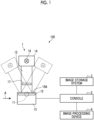
- Fig. 1 is a diagram schematically illustrating a configuration of a radiography system to which an image processing device according to an embodiment of the present disclosure is applied
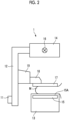
- Fig. 2 is a diagram illustrating a mammography apparatus in the radiography system as viewed from a direction of an arrow A in Fig. 1
- a radiography system 100 images a breast M, which is an object, at a plurality of radiation source positions and acquires a plurality of radiographic images, that is, a plurality of projection images, in order to perform tomosynthesis imaging on the breast to generate tomographic images.
- the radiography system 100 comprises a mammography apparatus 1, a console 2, an image storage system 3, and an image processing device 4.
- the mammography apparatus 1 comprises an arm portion 12 that is connected to a base (not illustrated) by a rotation shaft 11.
- An imaging table 13 is attached to one end of the arm portion 12, and a radiation emitting unit 14 is attached to the other end of the arm portion 12 so as to face the imaging table 13.
- the arm portion 12 is configured such that only the end to which the radiation emitting unit 14 is attached can be rotated. Therefore, the imaging table 13 is fixed, and only the radiation emitting unit 14 can be rotated.
- the radiation detector 15 has a detection surface 15A for radiation.
- a circuit substrate including a charge amplifier that converts a charge signal read from the radiation detector 15 into a voltage signal, a correlated double sampling circuit that samples the voltage signal output from the charge amplifier, and an analog-digital (AD) conversion unit that converts the voltage signal into a digital signal is provided in the imaging table 13.
- AD analog-digital
- a radiation source 16 is accommodated in the radiation emitting unit 14.
- the radiation source 16 emits, for example, X-rays as the radiation.
- the console 2 controls the timing when the radiation source 16 emits the radiation and the radiation generation conditions of the radiation source 16, that is, the selection of target and filter materials, a tube voltage, an irradiation time, and the like.
- the arm portion 12 is provided with a compression plate 17 that is disposed above the imaging table 13 and presses and compresses the breast M, a support portion 18 that supports the compression plate 17, and a movement mechanism 19 that moves the support portion 18 in an up-down direction in Figs. 1 and 2 .
- a compression thickness is input to the console 2.
- the console 2 has a function of controlling the mammography apparatus 1 using, for example, an imaging order and various kinds of information acquired from a radiology information system (RIS) (not illustrated) or the like through a network, such as a wireless communication local area network (LAN), and instructions or the like directly issued by a radiology technician or the like.
- RIS radiology information system
- LAN wireless communication local area network
- the console 2 directs the mammography apparatus 1 to perform the tomosynthesis imaging on the breast M, acquires a plurality of projection images as described below, and reconstructs the plurality of projection images to generate a plurality of tomographic images.
- a server computer is used as the console 2.
- the image storage system 3 is a system that stores image data such as radiographic images and tomographic images captured by the mammography apparatus 1.
- the image storage system 3 extracts an image corresponding to a request from, for example, the console 2 and the image processing device 4 from the stored images and transmits the image to a device that is the source of the request.
- a specific example of the image storage system 3 is a picture archiving and communication system (PACS).
- PACS picture archiving and communication system
- the image processing device 4 is a computer, such as a workstation, a server computer, or a personal computer, and comprises a central processing unit (CPU) 21, a non-volatile storage 23, and a memory 26 as a temporary storage area.
- the image processing device 4 comprises a display 24, such as a liquid crystal display, an input device 25, such as a keyboard and a mouse, and a network interface (I/F) 27 that is connected to a network (not illustrated).
- the CPU 21, the storage 23, the display 24, the input device 25, the memory 26, and the network I/F 27 are connected to a bus 28.
- the CPU 21 is an example of a processor according to the present disclosure.
- the storage 23 is implemented by, for example, a hard disk drive (HDD), a solid state drive (SSD), and a flash memory.
- An image processing program 22 installed in the image processing device 4 is stored in the storage 23 as a storage medium.
- the CPU 21 reads out the image processing program 22 from the storage 23, expands the image processing program 22 in the memory 26, and executes the expanded image processing program 22.
- the image processing program 22 is stored in a storage device of a server computer connected to the network or a network storage in a state in which it can be accessed from the outside and is downloaded and installed in the computer constituting the image processing device 4 as required.
- the programs are recorded on a recording medium, such as a digital versatile disc (DVD) or a compact disc read only memory (CD-ROM), are distributed, and are installed in the computer constituting the image processing device 4 from the recording medium.
- Fig. 4 is a diagram illustrating the functional configuration of the image processing device according to the first embodiment.
- the image processing device 4 comprises an image acquisition unit 30, a structure-of-interest detection unit 31, a frequency decomposition unit 32, a selection unit 33, a combination unit 34, and a display control unit 35.
- the CPU 21 executes the image processing program 22 to function as the image acquisition unit 30, the structure-of-interest detection unit 31, the frequency decomposition unit 32, the selection unit 33, the combination unit 34, and the display control unit 35.
- the image acquisition unit 30 acquires the tomographic image acquired by the imaging performed by the mammography apparatus 1 under the control of the console 2.
- the image acquisition unit 30 acquires the tomographic image from the console 2 or the image storage system 3 through the network I/F 27.
- Fig. 5 is a diagram illustrating the acquisition of the projection images Gi.
- the radiation source 16 is moved to each of radiation source positions S1, S2, ⁇ , and Sn.
- the radiation source 16 is driven at each radiation source position to irradiate the breast M with radiation.
- the radiation detector 15 detects the radiation transmitted through the breast M to acquire projection images G1, G2, ⁇ , and Gn corresponding to the radiation source positions S1 to Sn, respectively.
- the breast M is irradiated with the same dose of radiation.
- a radiation source position Sc is a radiation source position where an optical axis X0 of the radiation emitted from the radiation source 16 is orthogonal to the detection surface 15A of the radiation detector 15. It is assumed that the radiation source position Sc is referred to as a reference radiation source position Sc.
- a known back projection method such as a simple back projection method or a filtered back projection method
- a three-dimensional coordinate position in a three-dimensional space including the breast M is set, the pixel values of the corresponding pixels in the plurality of projection images Gi are reconstructed for the set three-dimensional coordinate position, and pixel values at the coordinate positions of the pixels are calculated.
- the console 2 directly transmits the generated tomographic images Dj to the image processing device 4 or transmits the generated tomographic images Dj to the image storage system 3.
- the structure-of-interest detection unit 31 detects a structure of interest from the plurality of tomographic images Dj.
- a tumor, a spicula, and a calcification included in the breast M are detected as the structures of interest.
- Fig. 7 is a diagram illustrating the detection of the structures of interest.
- the tomographic image D1 includes a calcification K13.
- the tomographic image D2 includes a tumor K21.
- the tomographic image D3 includes a tumor K31 which is contiguous with the tumor K21 in the tomographic image D2 in the breast M and a spicula K32.
- the tomographic image D4 includes a tumor K41a which is contiguous with the tumor K21 in the tomographic image D2 and the tumor K31 in the tomographic image D3 in the breast M, a tumor K41b which is present only in the tomographic image D4, and a spicula K42.
- the tomographic image D5 includes a spicula K52.
- the tomographic image D6 includes a calcification K63.
- the structure-of-interest detection unit 31 detects the structure of interest from the tomographic images Dj using a known computer-aided diagnosis (that is, CAD) algorithm.
- CAD computer-aided diagnosis
- the probability (likelihood) that the pixel in the tomographic images Dj will be the structure of interest is derived, and a pixel having a probability equal to or greater than a predetermined threshold value is detected as the structure of interest.
- the CAD algorithm is prepared for each type of structure of interest. In this embodiment, a CAD algorithm for detecting a tumor, a CAD algorithm for detecting a spicula, and a CAD algorithm for detecting a calcification are prepared.
- the detection of the structure of interest is not limited to the method using the CAD.
- the structure of interest may be detected from the tomographic images Dj by a filtering process using a filter for detecting the structure of interest, a detection model which has been subjected to machine learning by deep learning and the like to detect the structure of interest, and the like.
- the structure-of-interest detection unit 31 detects the tumor, the spicula, and the calcification as the structures of interest from the tomographic images D1 to D6 illustrated in Fig. 7 and derives a detection result R1 of the tumor, a detection result R2 of the spicula, and a detection result R3 of the calcification as illustrated in Fig. 8 .
- the detection result R1 of the tumor the tumor is detected in the tomographic images D2 to D4.
- the detection result R2 of the spicula the spicula is detected in the tomographic images D3 to D5.
- the detection result R3 of the calcification the calcification is detected in the tomographic images D1 and D6.
- the frequency decomposition unit 32 performs frequency decomposition on each of the plurality of tomographic images Dj to derive a plurality of band tomographic images indicating frequency components in each of a plurality of frequency bands for each of the plurality of tomographic images Dj.
- any known methods such as wavelet transform and Fourier transform, can be used as a frequency decomposition method, in addition to a method for performing multiple resolution transformation on a radiographic image.
- the number of bands obtained by frequency decomposition may be two or more.
- a low frequency band, a medium frequency band, and a high frequency band are described as the frequency bands.
- the high frequency band includes the largest number of frequency components, followed by the medium frequency band and the low frequency band in this order.
- the low frequency band, the medium frequency band, and the high frequency band can be set in any manner.
- the number of bands obtained by the frequency decomposition is two, it is assumed that the lower frequency band is referred to as a medium-low frequency band and the higher frequency band is referred to as a high frequency band.
- the low frequency band and the medium frequency band may be collectively referred to as the medium-low frequency band.
- Fig. 9 is a diagram illustrating band tomographic images.
- a medium-low frequency band MLf and a high frequency band Hf are illustrated as a plurality of frequency bands.
- the high frequency band Hf corresponds to a first frequency band according to the present disclosure
- the medium-low frequency band MLf corresponds to a second frequency band according to the present disclosure.
- the band tomographic images in the medium-low frequency band MLf are represented by DML1 to DML6 and the band tomographic images in the high frequency band Hf are represented by DH1 to DH6.
- the band tomographic images DML1 to DML6 in the medium-low frequency band MLf include only the tumor having a relatively large structure among the tumor, the spicula, and the calcification included in the tomographic images D1 to D6.
- the band tomographic images DH1 to DH6 in the high frequency band include the spicula and the calcification having a fine structure and the tumor having a fine structure.
- the selection unit 33 selects a tomographic image from the plurality of tomographic images Dj according to the type of the structure of interest and the frequency band. Specifically, in the first embodiment, the selection unit 33 selects a band tomographic image corresponding to the tomographic image, in which the structure of interest has been detected, from the plurality of band tomographic images for each pixel, which corresponds to the pixels of a composite two-dimensional image CG0 which will be described below, in the plurality of band tomographic images according to the type of the structure of interest and the frequency band.
- the selection unit 33 associates the position of the structure of interest in the tomographic images Dj with the positions of the band tomographic images DMLj and DHj for each type of structure of interest detected by the structure-of-interest detection unit 31.
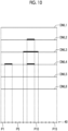
- Fig. 10 is a diagram illustrating the selection of the band tomographic image for the tumor in the medium-low frequency band.
- Fig. 11 is a diagram illustrating the selection of the band tomographic image for the tumor in the high frequency band.
- Fig. 12 is a diagram illustrating the selection of the band tomographic image for the spicula in the high frequency band.
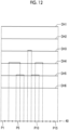
- Fig. 13 is a diagram illustrating the selection of the band tomographic image for the calcification in the high frequency band.
- Figs. 10 to 13 schematically illustrate the tomographic images one-dimensionally. Further, in Figs.
- an index 40 for showing a correspondence relationship between the pixels of the band tomographic image and the pixels of the composite two-dimensional image CG0 is one-dimensionally illustrated.
- the pixel of the detected structure of interest is illustrated to be thicker than the pixels other than the structure of interest.
- the pixel of the tumor is painted black.
- the pixel of the spicula is painted white.
- the pixel of the calcification is vertically hatched.
- 15 pixels P1 to P15 corresponding to the pixels of the composite two-dimensional image CG0 are illustrated.
- the selection unit 33 selects all of the band tomographic images including the tumor for each pixel, which corresponds to the pixels of the composite two-dimensional image CG0, in a plurality of band tomographic images in the medium-low frequency band MLf. As illustrated in Fig. 10 , in the pixels P1, P4 to P6, and P11 to P15 of the band tomographic images DMLj in the medium-low frequency band MLf, no tumor is detected in all of the band tomographic images DMLj. Therefore, for the tumor, the selection unit 33 does not select any band tomographic image for the pixels P1, P4 to P6, and P11 to P15.
- the selection unit 33 selects the band tomographic image DML4 for the pixels P2 and P3.
- the tumor is detected only in the band tomographic image DML3. Therefore, the selection unit 33 selects the band tomographic image DML3 for the pixels P7 and P10.
- the selection unit 33 selects all of the band tomographic images DML2 to DML4 in which the tumor has been detected for the pixels P8 and P9.
- the selection unit 33 selects one band tomographic image that best represents the tumor for each pixel, which corresponds to the pixels of the composite two-dimensional image CG0, in the plurality of band tomographic images.
- the selection unit 33 does not select any band tomographic image for the pixels P1, P4 to P6, and P11 to P15. Further, in the pixels P2 and P3, the tumor is detected only in the band tomographic image DH4.
- the selection unit 33 selects the band tomographic image DH4 for the pixels P2 and P3.
- the tumor is detected only in the band tomographic image DH3. Therefore, the selection unit 33 selects the band tomographic image DH3 for the pixels P7 and P10.
- the tumor is detected in the band tomographic images DH2 to DH4.
- the tumor detected in the band tomographic images DH3 is the largest, and the band tomographic image DH3 among the band tomographic images DH2 to DH4 best represents the tumor.
- the selection unit 33 selects the band tomographic image DH3 for the pixels P8 and P9. Moreover, instead of the largest tumor, a band tomographic image including the tumor having the highest probability (likelihood) derived by the structure-of-interest detection unit 31 at the time of detection may be selected.
- the selection unit 33 selects one band tomographic image that best represents the spicula for each pixel, which corresponds to the pixels of the composite two-dimensional image CG0, in the plurality of band tomographic images only in the high frequency band Hf. As illustrated in Fig. 12 , in the pixels P1, P2, P7, and P12 to P15, no spicula is detected in all of the band tomographic images DHj.
- the selection unit 33 does not select any band tomographic image DHj for the pixels P1, P2, P7, and P12 to P15.
- the spicula is detected only in the band tomographic image DH4. Therefore, the selection unit 33 selects the band tomographic image DH4 for the pixels P3, P4, and P11. Further, in the pixels P5 and P10, the spicula is detected in the band tomographic images DH4 and DH5.
- the selection unit 33 selects the band tomographic image DH4 for the pixels P5 and P10.
- a tomographic image including the spicula having the highest probability (likelihood) derived by the structure-of-interest detection unit 31 at the time of detection may be selected.
- the selection unit 33 selects the band tomographic image DH5 for the pixels P6 and P9. Further, in the pixel P8, the spicula is detected in the band tomographic image DH3. Therefore, the selection unit 33 selects the band tomographic image DH3 for the pixel P8.
- the selection unit 33 selects one band tomographic image that best represents the calcification for each pixel, which corresponds to the pixels of the composite two-dimensional image CG0, in the plurality of band tomographic images only in the high frequency band Hf. As illustrated in Fig. 13 , in the pixels P1 to P11, P13, and P15, the calcification is not detected in all of the band tomographic images DHj. Therefore, for the calcification, the selection unit 33 does not select any band tomographic image for the pixels P1 to P11, P13, and P15.
- the selection unit 33 selects the band tomographic image DH1 for the pixel P12.
- the calcification is detected only in the band tomographic image DH6. Therefore, the selection unit 33 selects the band tomographic image DH6 for the pixel P14.
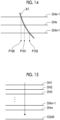
- one spicula K7 spreads two-dimensionally in a direction orthogonal to the tomographic plane and is present across a plurality of band tomographic images DHk-1, DHk, and DHk+1.
- the spicula is detected in a pixel P100 for the band tomographic image DHk-1, is detected in a pixel P101 for the band tomographic image DHk, and is detected in a pixel P102 for the band tomographic image DHk+1. Therefore, in a case in which the spicula K7 is present in the breast M as illustrated in Fig. 14 and the band tomographic image DHk illustrated in Fig.
- a plurality of band tomographic images DHk-1 and DHk+1 which are above and below the band tomographic image DHk and to which the spicula K7 included in the band tomographic image DHk is connected, are also selected.
- the combination unit 34 generates a composite two-dimensional image using the band tomographic images selected for each type of structure of interest by the selection unit 33 according to the frequency band. Specifically, the combination unit 34 generates a composite band two-dimensional image for each frequency band using the selected band tomographic images in the pixels of the band tomographic images, which correspond to the structure of interest, and performs frequency synthesis on the composite band two-dimensional images to generate a composite two-dimensional image.
- the composite two-dimensional image is a pseudo two-dimensional image corresponding to a simple two-dimensional image that is captured by irradiating the breast M with radiation emitted at the reference radiation source position Sc. In this embodiment, as illustrated in Fig.
- the combination unit 34 generates a composite band two-dimensional image CGHO by combining the pixel values of the corresponding pixels in each of the band tomographic images DHj along a viewing direction from the reference radiation source position Sc to the radiation detector 15, that is, along the optical axis X0 illustrated in Fig. 5 in a state in which the plurality of band tomographic images (only DHj is illustrated in Fig. 15 ) are stacked.
- the generation of the composite band two-dimensional image or the composite two-dimensional image will be described.
- Fig. 16 is a diagram illustrating the generation of the composite band two-dimensional image in the medium-low frequency band MLf.
- the combination unit 34 derives the added average value of the pixel values of all of the band tomographic images DML1 to DML6 and sets the added average value as the pixel values of the pixels P1, P4 to P6, and P11 to P15 of the composite band two-dimensional image CGMLO in the medium-low frequency band MLf.
- all of the band tomographic images are predetermined tomographic images according to the present disclosure.
- the combination unit 34 sets the pixel values of the pixels P2 and P3 of the band tomographic image DML4 as the pixel values of the pixels P2 and P3 of the composite band two-dimensional image CGMLO. Since the band tomographic image DML3 is selected for the pixels P7 and P10 of the band tomographic image DMLj, the combination unit 34 sets the pixel values of the pixels P7 and P10 of the band tomographic image DML3 as the pixel values of the pixels P7 and P10 of the composite band two-dimensional image CGMLO.
- the combination unit 34 sets the added value of the pixel values of the pixels P8 and P9 of the band tomographic images DML2 to DML4 as the pixel values of the pixels P8 and P9 of the composite band two-dimensional image CGMLO.
- a weighted added value, a weighted average value, or the like may be used instead of the added value.
- a weight for the band tomographic image DML3 may be larger than those for the band tomographic images DML2 and DML4.
- Fig. 17 is a diagram illustrating the generation of the composite band two-dimensional image in the high frequency band Hf.
- the band tomographic images DH3 and DH4 include both the tumor and the spicula. Therefore, in Fig. 17 , band tomographic images DH3-1 and DH4-1 including the detection result of only the tumor and band tomographic images DH3-2 and DH4-2 including the detection result of only the spicula are virtually illustrated side by side. Further, in the following description, the same figures as Fig. 17 are illustrated in the same manner as Fig. 17 .
- the combination unit 34 derives the added average value of the pixel values of all of the band tomographic images DH1 to DH6 and sets the added average value as the pixel values of the pixels P1, P13, and P15 of the composite band two-dimensional image CGHO in the high frequency band Hf. Since the band tomographic image DH4 in which the tumor has been detected is selected for the pixel P2, the combination unit 34 sets the pixel value of the pixel P2 of the band tomographic image DH4 as the pixel value of the pixel P2 of the composite band two-dimensional image CGHO.
- the combination unit 34 sets the pixel value of the pixel P3 of the band tomographic image DH4 as the pixel value of the pixel P3 of the composite band two-dimensional image CGHO. Since the band tomographic image DH4 in which the spicula has been detected is selected for the pixels P4 and P5, the combination unit 34 sets the pixel values of the pixels P4 and P5 of the band tomographic image DH4 as the pixel values of the pixels P4 and P5 of the composite band two-dimensional image CGHO.
- the combination unit 34 sets the pixel value of the pixel P6 of the band tomographic image DH5 as the pixel value of the pixel P6 of the composite band two-dimensional image CGHO. Since the band tomographic image DH3 in which the tumor has been detected is selected for the pixel P7, the combination unit 34 sets the pixel value of the pixel P7 of the band tomographic image DH3 as the pixel value of the pixel P7 of the composite band two-dimensional image CGHO.
- the combination unit 34 sets the pixel value of the pixel P8 of the band tomographic image DH3 as the pixel value of the pixel P8 of the composite band two-dimensional image CGHO.
- the band tomographic image DH3 in which the tumor has been detected and the band tomographic image DH5 in which the spicula has been detected are selected.
- the pixel values of the band tomographic images determined on the basis of priority given in the order of the tumor, the spicula, and the calcification are assigned. Therefore, the combination unit 34 sets the pixel value of the pixel P9 of the band tomographic image DH5 in which the spicula has been detected as the pixel value of the pixel P9 of the composite band two-dimensional image CGHO.
- the combination unit 34 sets the pixel value of the pixel P10 of the band tomographic image DH4 in which the spicula has been detected as the pixel value of the pixel P10 of the composite band two-dimensional image CGHO.
- the combination unit 34 sets the pixel value of the pixel P11 of the band tomographic image DH4 as the pixel value of the pixel P11 of the composite band two-dimensional image CGHO. Since the band tomographic image DH1 in which the calcification has been detected is selected for the pixel P12, the combination unit 34 sets the pixel value of the pixel P12 of the band tomographic image DH1 as the pixel value of the pixel P12 of the composite band two-dimensional image CGHO.
- the combination unit 34 sets the pixel value of the pixel P14 of the band tomographic image DH6 as the pixel value of the pixel P14 of the composite band two-dimensional image CGHO.
- the combination unit 34 performs frequency synthesis on the composite band two-dimensional image CGMLO in the medium-low frequency band MLf and the composite band two-dimensional image CGHO in the high frequency band Hf to generate a composite band two-dimensional image CG.
- a method corresponding to the frequency decomposition performed by the frequency decomposition unit 32 may be used as a frequency synthesis method.
- the frequency synthesis may be performed by inverse wavelet transform.
- the display control unit 35 displays the composite two-dimensional image CG0 generated by the combination unit 34 on the display 24.
- Fig. 18 is a diagram illustrating a composite two-dimensional image display screen. As illustrated in Fig. 18 , the composite two-dimensional image CG0 is displayed on a display screen 50 of the display 24. In addition, the composite two-dimensional image CG0 illustrated in Fig. 18 is generated from the tomographic images D1 to D6 illustrated in Fig. 7 . The composite two-dimensional image CG0 illustrated in Fig.
- the 18 clearly includes the calcification K13 included in the tomographic image D1, the tumor K31 included in the tomographic image D3, the tumor K41b included in the tomographic image D4, the calcification K63 included in the tomographic image D6, and the spiculae K32, K42, and K52 included in the tomographic images D3 to D5. Further, the illustration of the spiculae K32, K42, and K52 is omitted. The spiculae K32, K42, and K52 partially overlap the tumor K31, and the pixel values of the tumor K31 are replaced with the pixel values of the spiculae K42 and K52 included in the tomographic images D4 and D5.
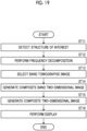
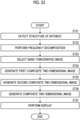
- Fig. 19 is a flowchart illustrating the process performed in the first embodiment.
- the plurality of tomographic images Dj are acquired in advance and stored in the storage 23.
- the process is started in a case in which the input device 25 receives a process start instruction from the operator, and the structure-of-interest detection unit 31 detects the structure of interest from each of the plurality of tomographic images Dj (Step ST11).
- the frequency decomposition unit 32 performs frequency decomposition on each of the plurality of tomographic images Dj to derive a plurality of band tomographic images indicating frequency components in each of a plurality of frequency bands for each of the plurality of tomographic images Dj (Step ST12).
- the selection unit 33 selects a band tomographic image corresponding to the tomographic image, in which the structure of interest has been detected, for each corresponding pixel in the plurality of band tomographic images from the plurality of band tomographic images according to the type of the structure of interest and the frequency band (Step ST13).
- the combination unit 34 generates the composite band two-dimensional images CGMLO and CGHO using the selected band tomographic images (Step ST14) and performs frequency synthesis on the composite band two-dimensional images CGMLO and CGHO to generate the composite two-dimensional image CG0 (Step ST15). Then, the display control unit 35 displays the composite two-dimensional image CG0 on the display 24 (Step ST16). Then, the process ends.
- frequency band decomposition is performed on the tomographic image, and a band tomographic image including the structure of interest is selected from a plurality of band tomographic images DMLj and DHj according to the type of the structure of interest and the frequency band. Then, in the region in which the structure of interest has been detected, the composite two-dimensional image CG0 is generated using the selected band tomographic image. Therefore, the composite two-dimensional image CG0 is generated using a smaller number of tomographic images in the region of the structure of interest, as compared to a case in which the composite two-dimensional image is generated by weighting and averaging all of the tomographic images as in the method disclosed in US9792703B .
- a fine structure of interest is not blurred.
- one band tomographic image that best represents the structure of interest is selected for each corresponding pixel in the plurality of band tomographic images. Therefore, it is possible to reduce the blurring of a fine structure of interest in the composite two-dimensional image CG0.
- the composite two-dimensional image CG0 is generated using a plurality of selected band tomographic images, which makes it possible to reflect the state of the structure of interest in the depth direction in the composite two-dimensional image CG0.
- one band tomographic image that best represents the structure of interest is selected for each pixel, which corresponds to the pixels of the composite two-dimensional image CG0, in the plurality of band tomographic images. Therefore, even in a case in which one structure of interest spreads in the direction in which the band tomographic images are arranged, that is, in the depth direction of the breast M while two-dimensionally spreading in a direction orthogonal to the optical axis X0 of radiation, a plurality of band tomographic images are selected for the structure of interest.
- the composite two-dimensional image CG0 is generated using a plurality of selected band tomographic images, which makes it possible to reflect the state of the structure of interest, which spreads in the depth direction while spreading two-dimensionally, in the composite two-dimensional image CG0.
- the pixel values of the band tomographic images determined on the basis of priority given in the order of the tumor, the spicula, and the calcification are assigned.
- the tumor has the highest degree of malignancy, followed by the spicula and the calcification in this order. Therefore, the selection of the band tomographic image based on the above-mentioned priority makes it possible to generate the composite two-dimensional image CG0 such that the structure of interest having a higher degree of malignancy is more conspicuous.
- the combination unit 34 combines a plurality of tomographic images Dj to generate a first composite two-dimensional image CG1.
- the combination unit 34 For each of the structures of interest, the combination unit 34 generates a composite band two-dimensional image for each frequency band using the selected band tomographic image in the pixel of the band tomographic image corresponding to the structure of interest and performs frequency synthesis on the composite band two-dimensional images to generate second composite two-dimensional images CG21, CG22, and CG23 for each of the structures of interest. Further, the combination unit 34 combines the second composite two-dimensional images CG21, CG22, and CG23 for each of the structures of interest with the first composite two-dimensional image CG1 to generate a composite two-dimensional image CG0.
- the combination unit 34 combines the plurality of tomographic images Dj to generate the first composite two-dimensional image CG1.
- the first composite two-dimensional image CG1 is generated by, for example, adding and averaging the pixel values of the corresponding pixels in the plurality of tomographic images Dj .
- the combination unit 34 generates the second composite two-dimensional images CG21, CG22, and CG23 according to the type of the structure of interest and the frequency band. That is, the second composite two-dimensional image CG21 for the tumor, the second composite two-dimensional image CG22 for the spicula, and the second composite two-dimensional image CG23 for the calcification are generated. First, the generation of the second composite two-dimensional image CG21 for the tumor will be described.
- the selection unit 33 selects the band tomographic image for each frequency band for each of the tumor, the spicula, and the calcification as in the first embodiment.
- the combination unit 34 generates a second composite band two-dimensional image CGML21 using only the selected band tomographic image only in the pixel in which the tumor has been detected.
- the generation of the second composite band two-dimensional image CGML21 in the medium-low frequency band MLf will be described.
- band tomographic images DML2 to DML4 are selected in the medium-low frequency band MLf.
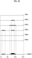
- Fig. 20 is a diagram illustrating the generation of the second composite band two-dimensional image in the medium-low frequency band for the tumor.
- the combination unit 34 derives the added average value of the pixel values of the band tomographic images DML1 to DML6 and sets the added average value as the pixel values of the pixels P1, P4 to P6, and P11 to P15 of the second composite band two-dimensional image CGML21 in the medium-low frequency band MLf. Since the band tomographic image DML4 is selected for the pixels P2 and P3, the combination unit 34 sets the pixel values of the pixels P2 and P3 of the band tomographic image DML4 as the pixel values of the pixels P2 and P3 of the second composite band two-dimensional image CGML21.
- the combination unit 34 sets the pixel values of the pixels P7 and P10 of the band tomographic image DML3 as the pixel values of the pixels P7 and P10 of the second composite band two-dimensional image CGMI,21. Since the band tomographic images DML2 to DML4 are selected for the pixels P8 and P9 of the band tomographic images DMLj, the combination unit 34 sets the added value of the pixel values of the pixels P8 and P9 of the band tomographic images DML2 to DML4 as the pixel values of the pixels P8 and P9 of the second composite band two-dimensional image CGMI,21.
- a weighted added value, a weighted average value, or the like may be used instead of the added value.
- a weight for the band tomographic image DML3 may be larger than those for the band tomographic images DML2 and DML4.
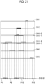
- Fig. 21 is a diagram illustrating the generation of the second composite band two-dimensional image in the high frequency band for the tumor.
- the combination unit 34 derives the added average value of the pixel values of the band tomographic images DH1 to DH6 and sets the added average value as the pixel values of the pixels P1, P4 to P6, and P11 to P15 of the second composite band two-dimensional image CGH21 in the high frequency band Hf.
- the combination unit 34 sets the pixel values of the pixels P2 and P3 of the band tomographic image DH4 as the pixel values of the pixels P2 and P3 of the second composite band two-dimensional image CGH21. Since the band tomographic image DH3 is selected for the pixels P7 to P10 of the band tomographic images DHj, the combination unit 34 sets the pixel values of the pixels P7 to P10 of the band tomographic image DH3 as the pixel values of the pixels P7 to P10 of the second composite band two-dimensional image CGH21.
- the combination unit 34 performs frequency synthesis on the second composite band two-dimensional image CGML21 in the medium-low frequency band MLf and the second composite band two-dimensional image CGH2 in the high frequency band Hf for the tumor to generate the second composite two-dimensional image CG21 for the tumor.
- the combination unit 34 generates the second composite band two-dimensional image CG22 using only the selected band tomographic image only in the pixel in which the spicula has been detected.
- the structure of the spicula is included only in the band tomographic images DHj in the high frequency band Hf.
- the combination unit 34 sets the added average value of the pixel values of all of the pixels P1 to P15 as the pixel values of the pixels P1 to P15 of a second composite band two-dimensional image CGMI,22 in the medium-low frequency band MLf.
- Fig. 22 is a diagram illustrating the generation of the second composite band two-dimensional image in the high frequency band for the spicula.
- the combination unit 34 derives the added average value of the pixel values of the band tomographic images DH1 to DH6 and sets the added average value as the pixel values of the pixels P1, P2, P7, and P12 to P15 of a second composite band two-dimensional image CGH22 in the high frequency band Hf.
- the combination unit 34 sets the pixel values of the pixels P3 to P5, P10, and P11 of the band tomographic image DH4 as the pixel values of the pixels P3 to P5, P10, and P11 of the second composite band two-dimensional image CGH22. Since the band tomographic image DH5 is selected for the pixels P6 and P9, the combination unit 34 sets the pixel values of the pixels P6 and P9 of the band tomographic image DH5 as the pixel values of the pixels P6 and P9 of the second composite band two-dimensional image CGH22.
- the combination unit 34 uses the pixel value of the pixel P8 of the band tomographic image DH3 as the pixel value of the pixel P8 of the second composite band two-dimensional image CGH22.
- the combination unit 34 performs frequency synthesis on the second composite band two-dimensional image CGMI,22 in the medium-low frequency band MLf and the second composite band two-dimensional image CGH22 in the high frequency band Hf for the spicula to generate the second composite two-dimensional image CG22 for the spicula.
- the combination unit 34 generates the second composite band two-dimensional image CG23 using only the selected band tomographic image only in the pixel in which the calcification has been detected.
- the structure of the calcification is included only in the band tomographic images DHj in the high frequency band Hf.
- the combination unit 34 sets the added average value of the pixel values of all of the pixels P1 to P15 as the pixel values of the pixels P1 to P15 of a second composite band two-dimensional image CGML23 in the medium-low frequency band MLf.
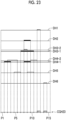
- Fig. 23 is a diagram illustrating the generation of the second composite band two-dimensional image in the high frequency band for the calcification.
- the combination unit 34 derives the added average value of the pixel values of the band tomographic images DH1 to DH6 and sets the added average value as the pixel values of the pixels P1 to P11, P13, and P15 of a second composite band two-dimensional image CGH23 in the high frequency band Hf.
- the combination unit 34 sets the pixel value of the pixel P12 of the band tomographic image DH1 in the high frequency band Hf as the pixel value of the pixel P12 of the second composite band two-dimensional image CGH23. Since the band tomographic image DH6 is selected for the pixel P14, the combination unit 34 sets the pixel value of the pixel P14 of the band tomographic image DH6 as the pixel value of the pixel P14 of the second composite band two-dimensional image CGH23.
- the combination unit 34 performs frequency synthesis on the second composite band two-dimensional image CGMI,23 in the medium-low frequency band MLf and the second composite band two-dimensional image CGH23 in the high frequency band Hf for the calcification to generates the second composite two-dimensional image CG23 for the calcification.
- the combination unit 34 sequentially combines the second composite two-dimensional image CG21 for the tumor, the second composite two-dimensional image CG22 for the spicula, and the second composite two-dimensional image CG23 for the calcification generated as described above with the first composite two-dimensional image CG1 to generate the composite two-dimensional image CG0.
- Fig. 24 is a diagram illustrating the generation of the composite two-dimensional image CG0 in the second embodiment. As illustrated in Fig. 24 , first, the combination unit 34 replaces the region of the tumor in the first composite two-dimensional image CG1 with the region of the tumor in the second composite two-dimensional image CG21 for the tumor to combine the second composite two-dimensional image CG21 for the tumor with the first composite two-dimensional image CG1. As a result, an intermediate composite two-dimensional image CG11 is generated.
- the combination unit 34 replaces the region of the spicula in the intermediate composite two-dimensional image CG11 with the region of the spicula in the second composite two-dimensional image CG22 for the spicula to combine the second composite two-dimensional image CG22 for the spicula with the intermediate composite two-dimensional image CG11.
- an intermediate composite two-dimensional image CG12 is generated.
- the combination unit 34 replaces the region of the calcification in the intermediate composite two-dimensional image CG12 with the region of the calcification in the second composite two-dimensional image CG23 for the calcification to combine the second composite two-dimensional image CG23 for the calcification with the intermediate composite two-dimensional image CG12.
- the composite two-dimensional image CG0 according to the second embodiment is generated.
- Fig. 25 is a flowchart illustrating the process performed in the second embodiment.
- the plurality of tomographic images Dj are acquired in advance and stored in the storage 23.
- the process is started in a case in which the input device 25 receives a process start instruction from the operator, and the structure-of-interest detection unit 31 detects the structure of interest from the plurality of tomographic images Dj (Step ST21).
- the frequency decomposition unit 32 performs frequency decomposition on each of the plurality of tomographic images Dj to derive a plurality of band tomographic images indicating frequency components in each of a plurality of frequency bands for each of the plurality of tomographic images Dj (Step ST22).
- the selection unit 33 selects a band tomographic image corresponding to the tomographic image, in which the structure of interest has been detected, from the plurality of band tomographic images for each corresponding pixel of the plurality of band tomographic images according to the type of the structure of interest and the frequency band (Step ST23).
- the combination unit 34 generates the first composite two-dimensional image CG1 from the plurality of tomographic images Dj (Step ST24).
- the process in Step ST24 may be performed before each of the processes in Steps ST21 to ST23 or may be performed in parallel to these processes.
- the combination unit 34 generates the second composite two-dimensional images CG21, CG22, and CG23 for the tumor, the spicula, and the calcification, respectively (Step ST25).
- the combination unit 34 sequentially combines the second composite two-dimensional images CG21, CG22, and CG23 for the tumor, the spicula, and the calcification with the first composite two-dimensional image CG1 to generate the composite two-dimensional image CG0 (Step ST26). Then, the display control unit 35 displays the composite two-dimensional image CG0 on the display 24 (Step ST27). Then, the process ends.
- the combination unit 34 combines the plurality of tomographic images Dj to generate the first composite two-dimensional image CG1.
- the combination unit 34 generates a composite band two-dimensional image for each frequency band using the selected band tomographic image in the pixels of the composite two-dimensional image CGO which correspond to the tumor and the spicula among the tumor, the spicula, and the calcification and performs frequency synthesis on the composite band two-dimensional images to generate the second composite two-dimensional images CG21 and CG22. Meanwhile, the combination unit 34 extracts the region of the calcification as a calcification region from the first composite two-dimensional image CG1. Further, the combination unit 34 combines the second composite two-dimensional images CG21 and G22 for the tumor and the spicula with the first composite two-dimensional image CG1 and further combines the calcification region to generate the composite two-dimensional image CG0.
- the generation of the first composite two-dimensional image CG1, the generation of the second composite band two-dimensional image CG21 for the tumor, and the generation of the second composite two-dimensional image CG22 for the spicula are performed by the combination unit 34 in the same manner as in the second embodiment.
- Fig. 26 is a diagram illustrating the extraction of the calcification region from the first composite two-dimensional image CG1.
- the combination unit 34 extracts regions corresponding to the calcification regions detected from each of the tomographic images Dj by the structure-of-interest detection unit 31 as calcification regions 42A and 42B from the first composite two-dimensional image CG1.
- Fig. 27 is a diagram illustrating the generation of the composite two-dimensional image CG0 in the third embodiment.
- the combination unit 34 replaces the region of the tumor in the first composite two-dimensional image CG1 with the region of the tumor in the second composite two-dimensional image CG21 for the tumor to combine the second composite two-dimensional image CG21 for the tumor with the first composite two-dimensional image CG1.
- an intermediate composite two-dimensional image CG1 1 is generated.
- the combination unit 34 replaces the region of the spicula in the intermediate composite two-dimensional image CG11 with the region of the spicula in the second composite two-dimensional image CG22 for the spicula to combine the second composite two-dimensional image CG22 for the spicula with the intermediate composite two-dimensional image CG11.
- an intermediate composite two-dimensional image CG12 is generated.
- the combination unit 34 replaces the calcification region of the intermediate composite two-dimensional image CG12 with the calcification regions 42A and 42B to combine the calcification regions 42A and 42B with the intermediate composite two-dimensional image CG12.
- the composite two-dimensional image CG0 according to the third embodiment is generated.
- Fig. 28 is a flowchart illustrating the process performed in the third embodiment.
- the plurality of tomographic images Dj are acquired in advance and stored in the storage 23.
- the process is started in a case in which the input device 25 receives a process start instruction from the operator, and the structure-of-interest detection unit 31 detects the structure of interest from each of the plurality of tomographic images Dj (Step ST31).
- the frequency decomposition unit 32 performs frequency decomposition on each of the plurality of tomographic images Dj to derive a plurality of band tomographic images indicating frequency components in each of a plurality of frequency bands for each of the plurality of tomographic images Dj (Step ST32).
- the selection unit 33 selects a band tomographic image corresponding to the tomographic image, in which the structure of interest has been detected, from the plurality of band tomographic images for each corresponding pixel of the plurality of band tomographic images according to the type of the structure of interest and the frequency band (Step ST33).
- the combination unit 34 generates the first composite two-dimensional image CG1 from the plurality of tomographic images Dj (Step ST34).
- the process in Step ST34 may be performed before each of the processes in Steps ST31 to ST33 or may be performed in parallel to these processes.
- the combination unit 34 generates the second composite two-dimensional images CG21 and CG22 for the tumor and the spicula, respectively (Step ST35).
- the combination unit 34 extracts the calcification regions 42A and 42B from the first composite two-dimensional image CG1 (Step ST36).
- the process in Step ST36 may be performed before any process after the first composite two-dimensional image CG1 is generated or may be performed in parallel to any process.
- the combination unit 34 sequentially combines the second composite two-dimensional images CG21 and CG22 for the tumor and the spicula with the first composite two-dimensional image CG1 to generate the intermediate composite two-dimensional image CG12 (Step ST37). Then, the combination unit 34 combines the calcification regions 42A and 42B with the intermediate composite two-dimensional image CG12 to generate the composite two-dimensional image CG0 (Step ST38). Further, the display control unit 35 displays the composite two-dimensional image CG0 on the display 24 (Step ST39). Then, the process ends.
- the selection of the band tomographic image is not limited thereto.
- all of the band tomographic images including the tumor may be selected for each pixel, which corresponds to the pixels of the composite two-dimensional image CG0, in the plurality of band tomographic images.
- this will be described as a fourth embodiment.
- the combination unit 34 In a case in which the band tomographic image is selected as in the fourth embodiment and the process according to the first embodiment is performed, the combination unit 34 generates the composite band two-dimensional image CGMLO in the medium-low frequency band MLf as in the first embodiment.
- the band tomographic image for the tumor is not selected in the high frequency band Hf. Therefore, the band tomographic images DH2 and DH3-1 are not selected even for the pixels P2 and P7 illustrated in Fig. 17 .
- the combination unit 34 derives the added average value of the pixel values of the pixels P2 and P7 in all of the band tomographic images DH1 to DH6 and sets the added average value as the pixel values of the pixels P2 and P7 of the composite band two-dimensional image CGHO in the high frequency band Hf as illustrated in Fig. 29 , similarly to the pixels P1, P13, and P15.
- the combination unit 34 generates the composite band two-dimensional image CGML21 in the medium-low frequency band MLf for the tumor as in the second embodiment.
- the band tomographic image for the tumor is not selected in the high frequency band Hf. Therefore, the band tomographic images DH2 and DH3-1 are not selected even for the pixels P2 and P7 illustrated in Fig. 21 .
- the combination unit 34 derives the added average value of the pixel values of the pixels P2 and P7 in all of the band tomographic images DH1 to DH6 and sets the added average value as the pixel values of the pixels P2 and P7 of the second composite band two-dimensional image CGH21 in the high frequency band Hf for the tumor as illustrated in Fig. 30 , similarly to the pixels P1, P4 to P6, and P11 to P15.
- one band tomographic image that best represents the tumor may be selected for each pixel, which corresponds to the pixels of the composite two-dimensional image CG0, in the plurality of band tomographic images.
- this will be described as a fifth embodiment.
- the selection unit 33 selects one band tomographic image that best represents the tumor for each pixel which corresponds to the pixels of the composite two-dimensional image CG0 in the medium-low frequency band MLf for the tumor. Specifically, the selection unit 33 selects the band tomographic image DML4 for the pixel P2 and P3 illustrated in Fig. 10 and selects the band tomographic image DML3 for the pixels P7 to P10. Further, in the fifth embodiment, the band tomographic images DML2 and DML4 illustrated in Fig. 10 are not selected for the pixels P8 and P9. In the high frequency band Hf, the band tomographic image is selected in the same manner as in each of the above-described embodiments.
- the combination unit 34 In a case in which the band tomographic image is selected as in the fifth embodiment and the process according to the first embodiment is performed, the combination unit 34 generates the composite band two-dimensional image CGHO in the high frequency band Hf as in the first embodiment. Meanwhile, in the fifth embodiment, for the tumor, even in the medium-low frequency band MLf, one band tomographic image that best represents the tumor is selected for each pixel, which corresponds to the pixels of the composite two-dimensional image CG0, in the plurality of band tomographic images. Therefore, only one band tomographic image DML3 is selected even for the pixels P8 and P9 illustrated in Fig. 16 .
- the combination unit 34 sets the pixel values of the pixels P8 and P9 of the band tomographic image DML3 as the pixel values of the pixels P8 and P9 of the composite band two-dimensional image CGMLO in the medium-low frequency band MLf as illustrated in Fig. 31 .
- the combination unit 34 generates the second composite band two-dimensional image CGH21 in the high frequency band Hf for the tumor as in the second embodiment.
- the combination unit 34 even in the medium-low frequency band MLf, one band tomographic image that best represents the tumor is selected for each pixel, which corresponds to the pixels of the composite two-dimensional image CG0, in the plurality of band tomographic images. Therefore, only one band tomographic image DML3 is selected even for the pixels P8 and P9 illustrated in Fig. 20 .
- the combination unit 34 sets the pixel values of the pixels P8 and P9 of the band tomographic image DML3 as the pixel values of the pixels P8 and P9 of the composite band two-dimensional image CGML21 in the medium-low frequency band MLf for the tumor as illustrated in Fig. 32 .
- one band tomographic image that best represents the tumor may be selected for each pixel, which corresponds to the pixels of the composite two-dimensional image CG0, in the plurality of band tomographic images.
- this will be described as a sixth embodiment.
- the selection unit 33 selects one band tomographic image that best represents the tumor for each pixel, which corresponds to the pixels of the composite two-dimensional image CG0, only in the medium-low frequency band MLf for the tumor. Specifically, the selection unit 33 selects the band tomographic image DML4 for the pixel P2 and P3 illustrated in Fig. 10 and selects the band tomographic image DML3 for the pixels P7 to P10. Meanwhile, in the sixth embodiment, the band tomographic image is not selected in the high frequency band Hf for the tumor.
- the combination unit 34 In a case in which the band tomographic image is selected as in the sixth embodiment and the process according to the first embodiment is performed, the combination unit 34 generates the composite band two-dimensional image CGHO in the high frequency band Hf as in the fourth embodiment. Meanwhile, in the medium-low frequency band MLf, the combination unit 34 generates the composite band two-dimensional image CGMLO in the medium-low frequency band MLf as in the fifth embodiment.
- the combination unit 34 in a case in which the band tomographic image is selected as in the sixth embodiment and the process according to the second embodiment is performed, the combination unit 34 generates the second composite band two-dimensional image CGH21 in the high frequency band Hf for the tumor as in the fourth embodiment. Meanwhile, in the medium-low frequency band MLf, the combination unit 34 generates the composite band two-dimensional image CGML21 in the medium-low frequency band MLf for the tumor as in the fifth embodiment.
- the added average value of the corresponding pixels of the band tomographic images is set as the pixel values of the composite band two-dimensional image.
- the present disclosure is not limited thereto.
- the added average value of the pixel values of the corresponding pixels of the tomographic image Dj is used as the pixel values of the first composite two-dimensional image CG1.
- the present disclosure is not limited thereto.
- the added average value of the pixel values of the corresponding pixels of the band tomographic images DMLj is set as the pixel values of the second composite band two-dimensional image CGML22.
- the present disclosure is not limited thereto.
- other known techniques that use a weighted average value, a median value, or the like as the pixel value can be applied.
- a minimum intensity projection method using the minimum value of the corresponding pixels in each band tomographic image or each tomographic image or a maximum intensity projection method using the maximum value may be used.
- a band tomographic image or a tomographic image including a pixel having the minimum value or the maximum value is a predetermined tomographic image according to the present disclosure.
- the average value of the corresponding pixels in each band tomographic image or each tomographic image may be derived, a pixel having a value whose difference from the average value is smaller than a predetermined set value may be regarded as a noise pixel that is greatly affected by noise, and the pixel values of the composite band two-dimensional image or the composite two-dimensional image may be derived excluding the noise pixel.
- a variance value of pixel values in a predetermined region including the pixels may be derived, a pixel having a variance value that is smaller than a predetermined set value may be regarded as a noise pixel, and the pixel values of the composite band two-dimensional image or the composite two-dimensional image may be derived excluding the noise pixel.
- a band tomographic image or a tomographic image having pixels that are not the noise pixel is the predetermined tomographic image according to the present disclosure.
- a process that detects the edge of a structure included in each band tomographic image or each tomographic image may be performed.
- the pixel values of the pixels including the edge may be used as the pixel values of the composite band two-dimensional image or the composite two-dimensional image.
- a band tomographic image or a tomographic image having the pixels including the edge is the predetermined tomographic image according to the present disclosure.
- the present invention is not limited thereto.
- the technology of the present disclosure can be applied even in a case in which at least one type of structure of interest among the tumor, the spicula, and the calcification is detected.
- the band tomographic image may be selected according to only the frequency band.
- the radiation in each of the above-described embodiments is not particularly limited.
- ⁇ -rays or ⁇ -rays can be applied in addition to the X-rays.
- the following various processors can be used as a hardware structure of processing units performing various processes, such as the image acquisition unit 30, the structure-of-interest detection unit 31, the frequency decomposition unit 32, the selection unit 33, the combination unit 34, and the display control unit 35.
- the various processors include, for example, a CPU which is a general-purpose processor executing software (program) to function as various processing units as described above, a programmable logic device (PLD), such as a field programmable gate array (FPGA), which is a processor whose circuit configuration can be changed after manufacture, and a dedicated electric circuit, such as an application specific integrated circuit (ASIC), which is a processor having a dedicated circuit configuration designed to perform a specific process.
- PLD programmable logic device
- FPGA field programmable gate array
- ASIC application specific integrated circuit
- One processing unit may be configured by one of the various processors or a combination of two or more processors of the same type or different types (for example, a combination of a plurality of FPGAs or a combination of a CPU and an FPGA).
- a plurality of processing units may be configured by one processor.
- a first example of the configuration in which a plurality of processing units are configured by one processor is an aspect in which one processor is configured by a combination of one or more CPUs and software and functions as a plurality of processing units.
- a representative example of this aspect is a client computer or a server computer.
- a second example of the configuration is an aspect in which a processor that implements the functions of the entire system including a plurality of processing units using one integrated circuit (IC) chip is used.
- IC integrated circuit
- a representative example of this aspect is a system-on-chip (SoC).
- SoC system-on-chip
- various processing units are configured by using one or more of the various processors as a hardware structure.
- an electric circuit obtained by combining circuit elements, such as semiconductor elements, can be used as the hardware structure of the various processors.
Landscapes
- Engineering & Computer Science (AREA)
- Health & Medical Sciences (AREA)
- Life Sciences & Earth Sciences (AREA)
- Physics & Mathematics (AREA)
- Medical Informatics (AREA)
- Theoretical Computer Science (AREA)
- Nuclear Medicine, Radiotherapy & Molecular Imaging (AREA)
- General Physics & Mathematics (AREA)
- General Health & Medical Sciences (AREA)
- Radiology & Medical Imaging (AREA)
- Pathology (AREA)
- Surgery (AREA)
- High Energy & Nuclear Physics (AREA)
- Biophysics (AREA)
- Biomedical Technology (AREA)
- Heart & Thoracic Surgery (AREA)
- Molecular Biology (AREA)
- Optics & Photonics (AREA)
- Animal Behavior & Ethology (AREA)
- Veterinary Medicine (AREA)
- Public Health (AREA)
- Computer Vision & Pattern Recognition (AREA)
- Quality & Reliability (AREA)
- Pulmonology (AREA)
- Apparatus For Radiation Diagnosis (AREA)
Claims (15)
- Vorrichtung zur Bildverarbeitung, die zumindest einen Prozessor (21) umfasst,
wobei der Prozessor dazu konfiguriert ist:eine interessierende Struktur aus einer Vielzahl von tomographischen Bildern zu detektieren, die eine Vielzahl von tomographischen Ebenen eines Objekts anzeigen;ein tomographisches Bild aus der Vielzahl von tomographischen Bildern gemäß einem Frequenzband in einem Bereich auszuwählen, in dem die interessierende Struktur detektiert worden ist; undein zusammengesetztes zweidimensionales Bild zu erzeugen, unter Verwendung des ausgewählten tomographischen Bildes in dem Bereich, in dem die interessierende Struktur detektiert worden ist, und unter Verwendung eines vorbestimmten tomographischen Bildes in einem Bereich, in dem die interessierende Struktur nicht detektiert worden ist. - Vorrichtung zur Bildverarbeitung nach Anspruch 1,wobei der Prozessor dazu konfiguriert ist, eine Frequenzzerlegung an der Vielzahl von tomographischen Bildern durchzuführen, um eine Vielzahl von bandtomographischen Bildern für jedes einer Vielzahl von Frequenzbändern abzuleiten, um ein bandtomographisches Bild auszuwählen, das dem tomographischen Bild entspricht, in dem die interessierende Struktur für jedes Pixel detektiert wurde, das einem Pixel des zusammengesetzten zweidimensionalen Bildes entspricht, in der Vielzahl von bandtomographischen Bildern gemäß dem Frequenzband; unddas zusammengesetzte zweidimensionale Bild unter Verwendung des ausgewählten bandtomographischen Bildes in dem Bereich zu erzeugen, in dem die interessierende Struktur detektiert wurde.
- Vorrichtung zur Bildverarbeitung nach Anspruch 2,
wobei der Prozessor dazu konfiguriert ist, unterschiedliche Anzahlen von bandtomographischen Bildern, die den tomographischen Bildern, in denen die interessierende Struktur detektiert wurde, entsprechen, aus der Vielzahl von bandtomographischen Bildern entsprechend dem Frequenzband auszuwählen. - Vorrichtung zur Bildverarbeitung nach Anspruch 2 oder 3,wobei die Vielzahl von Frequenzbändern ein erstes Frequenzband und ein zweites Frequenzband, das niedriger als das erste Frequenzband ist, umfasst undder Prozessor dazu konfiguriert ist, eine kleinere Anzahl von bandtomographischen Bildern in dem ersten Frequenzband als in dem zweiten Frequenzband auszuwählen.
- Vorrichtung zur Bildverarbeitung nach Anspruch 4,wobei der Prozessor dazu konfiguriert ist, alle bandtomographischen Bilder mit der interessierenden Struktur für jedes Pixel, das einem Pixel des zusammengesetzten zweidimensionalen Bildes entspricht, in der Vielzahl von bandtomographischen Bildern in dem zweiten Frequenzband auszuwählen, oderwobei der Prozessor dazu konfiguriert ist, ein bandtomographisches Bild auszuwählen, das die interessierende Struktur für jedes Pixel, das einem Pixel des zusammengesetzten zweidimensionalen Bildes entspricht, in der Vielzahl von bandtomographischen Bildern in dem zweiten Frequenzband am besten repräsentiert, und/oder wobei der Prozessor dazu konfiguriert ist, ein bandtomographisches Bild in der Vielzahl von bandtomographischen Bildern in dem ersten Frequenzband, das die interessierende Struktur für jede Pixelposition, die einer Pixelposition des zusammengesetzten zweidimensionalen Bildes entspricht, am besten repräsentiert, auszuwählen, und optional wobei das eine bandtomographische Bild, das die interessierende Struktur am besten repräsentiert, ein bandtomographisches Bild mit einer größten interessierenden Struktur oder ein bandtomographisches Bild mit einer höchsten Wahrscheinlichkeit in einem Fall, in dem die interessierende Struktur detektiert wird, ist.
- Vorrichtung zur Bildverarbeitung nach einem der Ansprüche 2 bis 5,
wobei der Prozessor ferner das bandtomographische Bild nach einem Typ der interessierenden Struktur auswählt, und wobei die interessierende Struktur optional ein Tumor, eine Spicula und eine Verkalkung ist. - Vorrichtung zur Bildverarbeitung nach einem der Ansprüche 2 bis 6,
wobei der Prozessor dazu konfiguriert ist, ein zusammengesetztes zweidimensionales Bandbild für jedes Frequenzband unter Verwendung des ausgewählten bandtomographischen Bildes in einem Pixel des bandtomographischen Bildes, das der interessierenden Struktur entspricht, zu erzeugen und eine Frequenzsynthese an den zusammengesetzten zweidimensionalen Bandbildern durchzuführen, um das zusammengesetzte zweidimensionale Bild zu erzeugen. - Vorrichtung zur Bildverarbeitung nach Anspruch 7,
wobei der Prozessor dazu konfiguriert ist, das zusammengesetzte zweidimensionale Bandbild zu erzeugen, das einen Pixelwert eines bandtomographischen Bildes aufweist, das auf der Grundlage einer vorbestimmten Priorität der interessierenden Struktur in einem Fall ermittelt wird, in dem eine Vielzahl der bandtomographischen Bilder in Pixeln ausgewählt wird, die einem Pixel des zusammengesetzten zweidimensionalen Bandbildes in der Vielzahl der bandtomographischen Bilder entsprechen. - Vorrichtung zur Bildverarbeitung nach Anspruch 6,wobei der Prozessor dazu konfiguriert ist, die Vielzahl von tomographischen Bildern zu kombinieren, um ein erstes zusammengesetztes zweidimensionales Bild zu erzeugen, ein zusammengesetztes zweidimensionales Bandbild für jedes Frequenzband unter Verwendung des bandtomographischen Bildes zu erzeugen, das für jeden Typ der interessierenden Struktur von Interesse in einem Pixel des bandtomographischen Bildes, das der Struktur von Interesse entspricht, ausgewählt wird, eine Frequenzsynthese an den zusammengesetzten zweidimensionalen Bandbildern durchzuführen, um ein zweites zusammengesetztes zweidimensionales Bild für jeden Typ der Struktur von Interesse zu erzeugen; unddas zweite zusammengesetzte zweidimensionale Bild, das für jeden Typ der Struktur von Interesse erzeugt wird, mit dem ersten zusammengesetzten zweidimensionalen Bild zu kombinieren, um das zusammengesetzte zweidimensionale Bild zu erzeugen.
- Vorrichtung zur Bildverarbeitung nach Anspruch 9,
wobei der Prozessor dazu konfiguriert ist, einen Pixelwert der interessierenden Struktur in dem ersten zusammengesetzten zweidimensionalen Bild durch einen Pixelwert der interessierenden Struktur in dem zweiten zusammengesetzten zweidimensionalen Bild zu ersetzen, um das zweite zusammengesetzte zweidimensionale Bild mit dem ersten zusammengesetzten zweidimensionalen Bild zu kombinieren. - Vorrichtung zur Bildverarbeitung nach Anspruch 10,
wobei der Prozessor dazu konfiguriert ist, das zusammengesetzte zweidimensionale Bild mit einem Pixelwert des zweiten zusammengesetzten zweidimensionalen Bildes zu erzeugen, der auf der Grundlage einer vorbestimmten Priorität der interessierenden Struktur in einem Fall ermittelt wird, in dem eine Vielzahl von Typen der interessierenden Strukturen in entsprechenden Pixeln der Vielzahl von zweiten zusammengesetzten zweidimensionalen Bildern enthalten sind. - Vorrichtung zur Bildverarbeitung nach Anspruch 6,wobei der Prozessor dazu konfiguriert ist, die Vielzahl tomographischer Bilder zu kombinieren, um ein erstes zusammengesetztes zweidimensionales Bild zu erzeugen;einen Bereich eines vorbestimmten spezifischen Typs einer interessierenden Struktur aus dem ersten zusammengesetzten zweidimensionalen Bild zu extrahieren; und ein zusammengesetztes zweidimensionales Bandbild für jedes Frequenzband zu erzeugen, wobei das bandtomographische Bild verwendet wird, das für jeden Typ interessierender Strukturen außer dem spezifischen Typ der interessierenden Struktur ausgewählt wird, und zwar in Pixeln des bandtomographischen Bildes, die den anderen interessierenden Strukturen entsprechen, um eine Frequenzsynthese an den zusammengesetzten zweidimensionalen Bandbildern durchzuführen, um ein zweites zusammengesetztes zweidimensionales Bild für jeden Typ der anderen Strukturen zu erzeugen , in Pixeln des bandtomographischen Bildes, die den anderen interessierenden Strukturen entsprechen, um eine Frequenzsynthese an den zusammengesetzten zweidimensionalen Bandbildern durchzuführen, um ein zweites zusammengesetztes zweidimensionales Bild für jeden Typ der anderen interessierenden Strukturen zu erzeugen, um die zweiten zusammengesetzten zweidimensionalen Bilder für die anderen interessierenden Strukturen mit dem ersten zusammengesetzten zweidimensionalen Bild zu kombinieren und den Bereich des spezifischen Typs der interessierenden Struktur mit dem ersten zusammengesetzten zweidimensionalen Bild zu kombinieren, mit dem die zweiten zusammengesetzten zweidimensionalen Bilder kombiniert wurden, um das zusammengesetzte zweidimensionale Bild zu erzeugen, und wobei optional die spezifische interessierende Struktur eine Verkalkung ist und die anderen interessierenden Strukturen ein Tumor und eine Spicula sind.
- Vorrichtung zur Bildverarbeitung nach Anspruch 12,
wobei der Prozessor dazu konfiguriert ist, einen Pixelwert der interessierenden Struktur in dem ersten zusammengesetzten zweidimensionalen Bild durch einen Pixelwert der interessierenden Struktur in dem zweiten zusammengesetzten zweidimensionalen Bild zu ersetzen, um das zweite zusammengesetzte zweidimensionale Bild mit dem ersten zusammengesetzten zweidimensionalen Bild zu kombinieren, und wobei der Prozessor optional dazu konfiguriert ist, das zusammengesetzte zweidimensionale Bild mit einem Pixelwert des zweiten zusammengesetzten zweidimensionalen Bildes zu erzeugen, der auf der Grundlage einer vorbestimmten Priorität der interessierenden Struktur in einem Fall ermittelt wurde, in dem eine Vielzahl von Typen der anderen interessierenden Strukturen in entsprechenden Pixeln der Vielzahl von zweiten zusammengesetzten zweidimensionalen Bildern enthalten sind, und optional wobei der Prozessor dazu konfiguriert ist, einen Pixelwert der interessierenden Struktur in dem ersten zusammengesetzten zweidimensionalen Bild, mit dem das zweite zusammengesetzte zweidimensionale Bild kombiniert wurde, durch einen Pixelwert des Bereichs des spezifischen Typs der interessierenden Struktur zu ersetzen, um den Bereich des spezifischen Typs der interessierenden Struktur mit dem ersten zusammengesetzten zweidimensionalen Bild zu kombinieren, mit dem das zweite zusammengesetzte zweidimensionale Bild kombiniert wurde. - Verfahren zur Bildverarbeitung, umfassend:Detektieren einer interessierenden Struktur aus einer Vielzahl von tomographischen Bildern, die eine Vielzahl von tomographischen Ebenen eines Objekts anzeigen;Auswählen eines tomographischen Bildes aus der Vielzahl von tomographischen Bildern gemäß einem Frequenzband in einem Bereich, in dem die interessierende Struktur detektiert wurde; undErzeugen eines zusammengesetzten zweidimensionalen Bildes unter Verwendung des ausgewählten tomographischen Bildes in dem Bereich, in dem die interessierende Struktur detektiert worden ist, und unter Verwendung eines vorbestimmten tomographischen Bildes in einem Bereich, in dem die interessierende Struktur nicht detektiert worden ist.
- Computerlesbares Speichermedium, das ein Bildverarbeitungsprogramm speichert, das einen Computer veranlasst, Folgendes auszuführen:eine Prozedur zum Detektieren einer interessierenden Struktur aus einer Vielzahl von tomographischen Bildern, die eine Vielzahl von tomographischen Ebenen eines Objekts anzeigen;eine Prozedur zum Auswählen eines tomographischen Bildes aus der Vielzahl von tomographischen Bildern gemäß einem Frequenzband in einem Bereich, in dem die interessierende Struktur detektiert wurde; undeine Prozedur zum Erzeugen eines zusammengesetzten zweidimensionalen Bildes unter Verwendung des ausgewählten tomographischen Bildes in dem Bereich, in dem die interessierende Struktur detektiert worden ist, und unter Verwendung eines vorbestimmten tomographischen Bildes in einem Bereich, in dem die interessierende Struktur nicht detektiert worden ist.
Applications Claiming Priority (2)
| Application Number | Priority Date | Filing Date | Title |
|---|---|---|---|
| JP2020047342 | 2020-03-18 | ||
| PCT/JP2021/004848 WO2021186956A1 (ja) | 2020-03-18 | 2021-02-09 | 画像処理装置、方法およびプログラム |
Publications (3)
| Publication Number | Publication Date |
|---|---|
| EP4122396A1 EP4122396A1 (de) | 2023-01-25 |
| EP4122396A4 EP4122396A4 (de) | 2023-08-23 |
| EP4122396B1 true EP4122396B1 (de) | 2024-12-11 |
Family
ID=77770838
Family Applications (1)
| Application Number | Title | Priority Date | Filing Date |
|---|---|---|---|
| EP21771277.7A Active EP4122396B1 (de) | 2020-03-18 | 2021-02-09 | Bildverarbeitungsvorrichtung, -verfahren und -programm |
Country Status (5)
| Country | Link |
|---|---|
| US (1) | US12307664B2 (de) |
| EP (1) | EP4122396B1 (de) |
| JP (1) | JP7321359B2 (de) |
| CN (1) | CN115297778B (de) |
| WO (1) | WO2021186956A1 (de) |
Family Cites Families (23)
| Publication number | Priority date | Publication date | Assignee | Title |
|---|---|---|---|---|
| US7831296B2 (en) | 2002-11-27 | 2010-11-09 | Hologic, Inc. | X-ray mammography with tomosynthesis |
| US10638994B2 (en) | 2002-11-27 | 2020-05-05 | Hologic, Inc. | X-ray mammography with tomosynthesis |
| US7616801B2 (en) | 2002-11-27 | 2009-11-10 | Hologic, Inc. | Image handling and display in x-ray mammography and tomosynthesis |
| US7123684B2 (en) | 2002-11-27 | 2006-10-17 | Hologic, Inc. | Full field mammography with tissue exposure control, tomosynthesis, and dynamic field of view processing |
| US8565372B2 (en) | 2003-11-26 | 2013-10-22 | Hologic, Inc | System and method for low dose tomosynthesis |
| US7760924B2 (en) | 2002-11-27 | 2010-07-20 | Hologic, Inc. | System and method for generating a 2D image from a tomosynthesis data set |
| US7577282B2 (en) | 2002-11-27 | 2009-08-18 | Hologic, Inc. | Image handling and display in X-ray mammography and tomosynthesis |
| US8571289B2 (en) | 2002-11-27 | 2013-10-29 | Hologic, Inc. | System and method for generating a 2D image from a tomosynthesis data set |
| US8768026B2 (en) | 2003-11-26 | 2014-07-01 | Hologic, Inc. | X-ray imaging with x-ray markers that provide adjunct information but preserve image quality |
| EP2602743B1 (de) | 2004-11-15 | 2014-11-05 | Hologic, Inc. | Erzeugung und Anzeige mit übereinstimmenden Geometrie von Mammogrammen und Tomosynthesebildern |
| EP3106094B1 (de) | 2004-11-26 | 2021-09-08 | Hologic, Inc. | Integriertes multimodus-mammographie-/tomosynthese-röntgensystem |
| US10008184B2 (en) * | 2005-11-10 | 2018-06-26 | Hologic, Inc. | System and method for generating a 2D image using mammography and/or tomosynthesis image data |
| JP2013000370A (ja) | 2011-06-17 | 2013-01-07 | Fujifilm Corp | 放射線画像撮影装置および方法 |
| JP2014534042A (ja) | 2011-11-27 | 2014-12-18 | ホロジック, インコーポレイテッドHologic, Inc. | マンモグラフィーおよび/またはトモシンセシス画像データを使用して2d画像を生成するためのシステムおよび方法 |
| US9805507B2 (en) | 2012-02-13 | 2017-10-31 | Hologic, Inc | System and method for navigating a tomosynthesis stack using synthesized image data |
| US8983156B2 (en) | 2012-11-23 | 2015-03-17 | Icad, Inc. | System and method for improving workflow efficiences in reading tomosynthesis medical image data |
| CA2899571A1 (en) | 2013-01-30 | 2014-08-07 | Japan Science And Technology Agency | Digital filter for image processing, image processing apparatus, printing medium, recording medium, image processing method, and program |
| EP2967473B1 (de) | 2013-03-15 | 2020-02-19 | Hologic, Inc. | System und verfahren zum navigieren eines tomosynthesestapels mit automatischer fokussierung |
| WO2016078958A1 (en) * | 2014-11-20 | 2016-05-26 | Koninklijke Philips N.V. | Method for generation of synthetic mammograms from tomosynthesis data |
| US9792703B2 (en) | 2015-07-06 | 2017-10-17 | Siemens Healthcare Gmbh | Generating a synthetic two-dimensional mammogram |
| EP3429474B1 (de) | 2016-06-07 | 2019-07-10 | Koninklijke Philips N.V. | Verbesserte präzision und auflösung von quantitativer bildgebung durch kombination von spektraler und nichtsprektraler materialzersetzung |
| JP6639357B2 (ja) * | 2016-08-24 | 2020-02-05 | 富士フイルム株式会社 | 画像処理装置、方法およびプログラム |
| JP6590773B2 (ja) * | 2016-09-08 | 2019-10-16 | 富士フイルム株式会社 | 画像処理装置、方法およびプログラム |
-
2021
- 2021-02-09 WO PCT/JP2021/004848 patent/WO2021186956A1/ja not_active Ceased
- 2021-02-09 JP JP2022508132A patent/JP7321359B2/ja active Active
- 2021-02-09 EP EP21771277.7A patent/EP4122396B1/de active Active
- 2021-02-09 CN CN202180021255.4A patent/CN115297778B/zh active Active
-
2022
- 2022-08-17 US US17/820,247 patent/US12307664B2/en active Active
Also Published As
| Publication number | Publication date |
|---|---|
| US20220392064A1 (en) | 2022-12-08 |
| CN115297778A (zh) | 2022-11-04 |
| JPWO2021186956A1 (de) | 2021-09-23 |
| US12307664B2 (en) | 2025-05-20 |
| WO2021186956A1 (ja) | 2021-09-23 |
| CN115297778B (zh) | 2025-08-08 |
| EP4122396A1 (de) | 2023-01-25 |
| JP7321359B2 (ja) | 2023-08-04 |
| EP4122396A4 (de) | 2023-08-23 |
Similar Documents
| Publication | Publication Date | Title |
|---|---|---|
| US11587215B2 (en) | Image processing device, image processing method, image processing program, image display device, image display method, and image display program | |
| US12417565B2 (en) | Image generation device, image generation program, learning device, learning program, image processing device, and image processing program | |
| US12488423B2 (en) | Image processing device, method for operating image processing device, and program for operating image processing device | |
| US20230206397A1 (en) | Image processing device, method for operating image processing device, and program for operating image processing device | |
| EP4122397B1 (de) | Bildverarbeitungsvorrichtung, -verfahren und -programm | |
| EP4122396B1 (de) | Bildverarbeitungsvorrichtung, -verfahren und -programm | |
| JP7209599B2 (ja) | 画像処理装置、方法およびプログラム | |
| US12327352B2 (en) | Image setting device, image setting method, and image setting program | |
| US20220343500A1 (en) | Image setting device, image setting method, and image setting program | |
| US12536649B2 (en) | Image processing device, image processing method, and image processing program for facilitating image diagnosis using mammography apparatus to generate composite two-dimensional tomographic image using selected tomographic image slices corresponding to detected spicula regions | |
| US20230146430A1 (en) | Image processing device, image processing method, and image processing program | |
| US12597126B2 (en) | Image setting device, image setting method, and image setting program | |
| US12419590B2 (en) | Image processing device, image processing method, and image processing program | |
| US11224397B2 (en) | Imaging control device, imaging control method, and imaging control program | |
| US12112479B2 (en) | Image processing device, image processing method, and image processing program |
Legal Events
| Date | Code | Title | Description |
|---|---|---|---|
| STAA | Information on the status of an ep patent application or granted ep patent |
Free format text: STATUS: THE INTERNATIONAL PUBLICATION HAS BEEN MADE |
|
| PUAI | Public reference made under article 153(3) epc to a published international application that has entered the european phase |
Free format text: ORIGINAL CODE: 0009012 |
|
| STAA | Information on the status of an ep patent application or granted ep patent |
Free format text: STATUS: REQUEST FOR EXAMINATION WAS MADE |
|
| 17P | Request for examination filed |
Effective date: 20220914 |
|
| AK | Designated contracting states |
Kind code of ref document: A1 Designated state(s): AL AT BE BG CH CY CZ DE DK EE ES FI FR GB GR HR HU IE IS IT LI LT LU LV MC MK MT NL NO PL PT RO RS SE SI SK SM TR |
|
| DAV | Request for validation of the european patent (deleted) | ||
| DAX | Request for extension of the european patent (deleted) | ||
| A4 | Supplementary search report drawn up and despatched |
Effective date: 20230720 |
|
| RIC1 | Information provided on ipc code assigned before grant |
Ipc: G06T 11/00 20060101ALI20230714BHEP Ipc: G06T 1/00 20060101ALI20230714BHEP Ipc: A61B 6/03 20060101ALI20230714BHEP Ipc: A61B 6/02 20060101ALI20230714BHEP Ipc: A61B 6/00 20060101AFI20230714BHEP |
|
| GRAP | Despatch of communication of intention to grant a patent |
Free format text: ORIGINAL CODE: EPIDOSNIGR1 |
|
| STAA | Information on the status of an ep patent application or granted ep patent |
Free format text: STATUS: GRANT OF PATENT IS INTENDED |
|
| INTG | Intention to grant announced |
Effective date: 20240708 |
|
| GRAS | Grant fee paid |
Free format text: ORIGINAL CODE: EPIDOSNIGR3 |
|
| GRAA | (expected) grant |
Free format text: ORIGINAL CODE: 0009210 |
|
| STAA | Information on the status of an ep patent application or granted ep patent |
Free format text: STATUS: THE PATENT HAS BEEN GRANTED |
|
| P01 | Opt-out of the competence of the unified patent court (upc) registered |
Free format text: CASE NUMBER: APP_56347/2024 Effective date: 20241015 |
|
| AK | Designated contracting states |
Kind code of ref document: B1 Designated state(s): AL AT BE BG CH CY CZ DE DK EE ES FI FR GB GR HR HU IE IS IT LI LT LU LV MC MK MT NL NO PL PT RO RS SE SI SK SM TR |
|
| REG | Reference to a national code |
Ref country code: GB Ref legal event code: FG4D |
|
| REG | Reference to a national code |
Ref country code: CH Ref legal event code: EP |
|
| REG | Reference to a national code |
Ref country code: DE Ref legal event code: R096 Ref document number: 602021023314 Country of ref document: DE |
|
| REG | Reference to a national code |
Ref country code: IE Ref legal event code: FG4D |
|
| REG | Reference to a national code |
Ref country code: LT Ref legal event code: MG9D |
|
| PG25 | Lapsed in a contracting state [announced via postgrant information from national office to epo] |
Ref country code: HR Free format text: LAPSE BECAUSE OF FAILURE TO SUBMIT A TRANSLATION OF THE DESCRIPTION OR TO PAY THE FEE WITHIN THE PRESCRIBED TIME-LIMIT Effective date: 20241211 |
|
| PG25 | Lapsed in a contracting state [announced via postgrant information from national office to epo] |
Ref country code: FI Free format text: LAPSE BECAUSE OF FAILURE TO SUBMIT A TRANSLATION OF THE DESCRIPTION OR TO PAY THE FEE WITHIN THE PRESCRIBED TIME-LIMIT Effective date: 20241211 |
|
| PG25 | Lapsed in a contracting state [announced via postgrant information from national office to epo] |
Ref country code: BG Free format text: LAPSE BECAUSE OF FAILURE TO SUBMIT A TRANSLATION OF THE DESCRIPTION OR TO PAY THE FEE WITHIN THE PRESCRIBED TIME-LIMIT Effective date: 20241211 |
|
| REG | Reference to a national code |
Ref country code: NL Ref legal event code: MP Effective date: 20241211 |
|
| PG25 | Lapsed in a contracting state [announced via postgrant information from national office to epo] |
Ref country code: ES Free format text: LAPSE BECAUSE OF FAILURE TO SUBMIT A TRANSLATION OF THE DESCRIPTION OR TO PAY THE FEE WITHIN THE PRESCRIBED TIME-LIMIT Effective date: 20241211 |
|
| PG25 | Lapsed in a contracting state [announced via postgrant information from national office to epo] |
Ref country code: NO Free format text: LAPSE BECAUSE OF FAILURE TO SUBMIT A TRANSLATION OF THE DESCRIPTION OR TO PAY THE FEE WITHIN THE PRESCRIBED TIME-LIMIT Effective date: 20250311 |
|
| PG25 | Lapsed in a contracting state [announced via postgrant information from national office to epo] |
Ref country code: GR Free format text: LAPSE BECAUSE OF FAILURE TO SUBMIT A TRANSLATION OF THE DESCRIPTION OR TO PAY THE FEE WITHIN THE PRESCRIBED TIME-LIMIT Effective date: 20250312 Ref country code: LV Free format text: LAPSE BECAUSE OF FAILURE TO SUBMIT A TRANSLATION OF THE DESCRIPTION OR TO PAY THE FEE WITHIN THE PRESCRIBED TIME-LIMIT Effective date: 20241211 |
|
| PG25 | Lapsed in a contracting state [announced via postgrant information from national office to epo] |
Ref country code: RS Free format text: LAPSE BECAUSE OF FAILURE TO SUBMIT A TRANSLATION OF THE DESCRIPTION OR TO PAY THE FEE WITHIN THE PRESCRIBED TIME-LIMIT Effective date: 20250311 |
|
| PG25 | Lapsed in a contracting state [announced via postgrant information from national office to epo] |
Ref country code: NL Free format text: LAPSE BECAUSE OF FAILURE TO SUBMIT A TRANSLATION OF THE DESCRIPTION OR TO PAY THE FEE WITHIN THE PRESCRIBED TIME-LIMIT Effective date: 20241211 |
|
| REG | Reference to a national code |
Ref country code: AT Ref legal event code: MK05 Ref document number: 1749709 Country of ref document: AT Kind code of ref document: T Effective date: 20241211 |
|
| PG25 | Lapsed in a contracting state [announced via postgrant information from national office to epo] |
Ref country code: SM Free format text: LAPSE BECAUSE OF FAILURE TO SUBMIT A TRANSLATION OF THE DESCRIPTION OR TO PAY THE FEE WITHIN THE PRESCRIBED TIME-LIMIT Effective date: 20241211 |
|
| PG25 | Lapsed in a contracting state [announced via postgrant information from national office to epo] |
Ref country code: PL Free format text: LAPSE BECAUSE OF FAILURE TO SUBMIT A TRANSLATION OF THE DESCRIPTION OR TO PAY THE FEE WITHIN THE PRESCRIBED TIME-LIMIT Effective date: 20241211 |
|
| PG25 | Lapsed in a contracting state [announced via postgrant information from national office to epo] |
Ref country code: IS Free format text: LAPSE BECAUSE OF FAILURE TO SUBMIT A TRANSLATION OF THE DESCRIPTION OR TO PAY THE FEE WITHIN THE PRESCRIBED TIME-LIMIT Effective date: 20250411 |
|
| PG25 | Lapsed in a contracting state [announced via postgrant information from national office to epo] |
Ref country code: PT Free format text: LAPSE BECAUSE OF FAILURE TO SUBMIT A TRANSLATION OF THE DESCRIPTION OR TO PAY THE FEE WITHIN THE PRESCRIBED TIME-LIMIT Effective date: 20250411 |
|
| PG25 | Lapsed in a contracting state [announced via postgrant information from national office to epo] |
Ref country code: EE Free format text: LAPSE BECAUSE OF FAILURE TO SUBMIT A TRANSLATION OF THE DESCRIPTION OR TO PAY THE FEE WITHIN THE PRESCRIBED TIME-LIMIT Effective date: 20241211 |
|
| PG25 | Lapsed in a contracting state [announced via postgrant information from national office to epo] |
Ref country code: AT Free format text: LAPSE BECAUSE OF FAILURE TO SUBMIT A TRANSLATION OF THE DESCRIPTION OR TO PAY THE FEE WITHIN THE PRESCRIBED TIME-LIMIT Effective date: 20241211 Ref country code: RO Free format text: LAPSE BECAUSE OF FAILURE TO SUBMIT A TRANSLATION OF THE DESCRIPTION OR TO PAY THE FEE WITHIN THE PRESCRIBED TIME-LIMIT Effective date: 20241211 |
|
| PG25 | Lapsed in a contracting state [announced via postgrant information from national office to epo] |
Ref country code: SK Free format text: LAPSE BECAUSE OF FAILURE TO SUBMIT A TRANSLATION OF THE DESCRIPTION OR TO PAY THE FEE WITHIN THE PRESCRIBED TIME-LIMIT Effective date: 20241211 |
|
| PG25 | Lapsed in a contracting state [announced via postgrant information from national office to epo] |
Ref country code: CZ Free format text: LAPSE BECAUSE OF FAILURE TO SUBMIT A TRANSLATION OF THE DESCRIPTION OR TO PAY THE FEE WITHIN THE PRESCRIBED TIME-LIMIT Effective date: 20241211 |
|
| PG25 | Lapsed in a contracting state [announced via postgrant information from national office to epo] |
Ref country code: IT Free format text: LAPSE BECAUSE OF FAILURE TO SUBMIT A TRANSLATION OF THE DESCRIPTION OR TO PAY THE FEE WITHIN THE PRESCRIBED TIME-LIMIT Effective date: 20241211 |
|
| PG25 | Lapsed in a contracting state [announced via postgrant information from national office to epo] |
Ref country code: SE Free format text: LAPSE BECAUSE OF FAILURE TO SUBMIT A TRANSLATION OF THE DESCRIPTION OR TO PAY THE FEE WITHIN THE PRESCRIBED TIME-LIMIT Effective date: 20241211 |
|
| REG | Reference to a national code |
Ref country code: DE Ref legal event code: R097 Ref document number: 602021023314 Country of ref document: DE |
|
| PG25 | Lapsed in a contracting state [announced via postgrant information from national office to epo] |
Ref country code: MC Free format text: LAPSE BECAUSE OF FAILURE TO SUBMIT A TRANSLATION OF THE DESCRIPTION OR TO PAY THE FEE WITHIN THE PRESCRIBED TIME-LIMIT Effective date: 20241211 |
|
| REG | Reference to a national code |
Ref country code: CH Ref legal event code: PL |
|
| PG25 | Lapsed in a contracting state [announced via postgrant information from national office to epo] |
Ref country code: DK Free format text: LAPSE BECAUSE OF FAILURE TO SUBMIT A TRANSLATION OF THE DESCRIPTION OR TO PAY THE FEE WITHIN THE PRESCRIBED TIME-LIMIT Effective date: 20241211 |
|
| PG25 | Lapsed in a contracting state [announced via postgrant information from national office to epo] |
Ref country code: LU Free format text: LAPSE BECAUSE OF NON-PAYMENT OF DUE FEES Effective date: 20250209 |
|
| PLBE | No opposition filed within time limit |
Free format text: ORIGINAL CODE: 0009261 |
|
| STAA | Information on the status of an ep patent application or granted ep patent |
Free format text: STATUS: NO OPPOSITION FILED WITHIN TIME LIMIT |
|
| PG25 | Lapsed in a contracting state [announced via postgrant information from national office to epo] |
Ref country code: CH Free format text: LAPSE BECAUSE OF NON-PAYMENT OF DUE FEES Effective date: 20250228 |
|
| 26N | No opposition filed |
Effective date: 20250912 |
|
| GBPC | Gb: european patent ceased through non-payment of renewal fee |
Effective date: 20250311 |
|
| REG | Reference to a national code |
Ref country code: BE Ref legal event code: MM Effective date: 20250228 |
|
| PG25 | Lapsed in a contracting state [announced via postgrant information from national office to epo] |
Ref country code: GB Free format text: LAPSE BECAUSE OF NON-PAYMENT OF DUE FEES Effective date: 20250311 |
|
| PGFP | Annual fee paid to national office [announced via postgrant information from national office to epo] |
Ref country code: FR Payment date: 20251231 Year of fee payment: 6 |
|
| PG25 | Lapsed in a contracting state [announced via postgrant information from national office to epo] |
Ref country code: BE Free format text: LAPSE BECAUSE OF NON-PAYMENT OF DUE FEES Effective date: 20250228 |
|
| PG25 | Lapsed in a contracting state [announced via postgrant information from national office to epo] |
Ref country code: IE Free format text: LAPSE BECAUSE OF NON-PAYMENT OF DUE FEES Effective date: 20250209 |
|
| PGFP | Annual fee paid to national office [announced via postgrant information from national office to epo] |
Ref country code: DE Payment date: 20251230 Year of fee payment: 6 |