EP4122389A1 - Breath sampling mask and system - Google Patents
Breath sampling mask and system Download PDFInfo
- Publication number
- EP4122389A1 EP4122389A1 EP22189298.7A EP22189298A EP4122389A1 EP 4122389 A1 EP4122389 A1 EP 4122389A1 EP 22189298 A EP22189298 A EP 22189298A EP 4122389 A1 EP4122389 A1 EP 4122389A1
- Authority
- EP
- European Patent Office
- Prior art keywords
- mask
- breath sampling
- breath
- sampling mask
- chamber
- Prior art date
- Legal status (The legal status is an assumption and is not a legal conclusion. Google has not performed a legal analysis and makes no representation as to the accuracy of the status listed.)
- Withdrawn
Links
Images





Classifications
-
- A—HUMAN NECESSITIES
- A61—MEDICAL OR VETERINARY SCIENCE; HYGIENE
- A61B—DIAGNOSIS; SURGERY; IDENTIFICATION
- A61B5/00—Measuring for diagnostic purposes; Identification of persons
- A61B5/02—Detecting, measuring or recording for evaluating the cardiovascular system, e.g. pulse, heart rate, blood pressure or blood flow
- A61B5/0205—Simultaneously evaluating both cardiovascular conditions and different types of body conditions, e.g. heart and respiratory condition
- A61B5/02055—Simultaneously evaluating both cardiovascular condition and temperature
-
- A—HUMAN NECESSITIES
- A61—MEDICAL OR VETERINARY SCIENCE; HYGIENE
- A61B—DIAGNOSIS; SURGERY; IDENTIFICATION
- A61B5/00—Measuring for diagnostic purposes; Identification of persons
- A61B5/08—Measuring devices for evaluating the respiratory organs
- A61B5/082—Evaluation by breath analysis, e.g. determination of the chemical composition of exhaled breath
-
- A—HUMAN NECESSITIES
- A61—MEDICAL OR VETERINARY SCIENCE; HYGIENE
- A61B—DIAGNOSIS; SURGERY; IDENTIFICATION
- A61B5/00—Measuring for diagnostic purposes; Identification of persons
- A61B5/68—Arrangements of detecting, measuring or recording means, e.g. sensors, in relation to patient
- A61B5/6801—Arrangements of detecting, measuring or recording means, e.g. sensors, in relation to patient specially adapted to be attached to or worn on the body surface
- A61B5/6802—Sensor mounted on worn items
- A61B5/6803—Head-worn items, e.g. helmets, masks, headphones or goggles
-
- A—HUMAN NECESSITIES
- A61—MEDICAL OR VETERINARY SCIENCE; HYGIENE
- A61B—DIAGNOSIS; SURGERY; IDENTIFICATION
- A61B2560/00—Constructional details of operational features of apparatus; Accessories for medical measuring apparatus
- A61B2560/02—Operational features
- A61B2560/0242—Operational features adapted to measure environmental factors, e.g. temperature, pollution
-
- A—HUMAN NECESSITIES
- A61—MEDICAL OR VETERINARY SCIENCE; HYGIENE
- A61B—DIAGNOSIS; SURGERY; IDENTIFICATION
- A61B5/00—Measuring for diagnostic purposes; Identification of persons
- A61B5/02—Detecting, measuring or recording for evaluating the cardiovascular system, e.g. pulse, heart rate, blood pressure or blood flow
- A61B5/021—Measuring pressure in heart or blood vessels
-
- A—HUMAN NECESSITIES
- A61—MEDICAL OR VETERINARY SCIENCE; HYGIENE
- A61B—DIAGNOSIS; SURGERY; IDENTIFICATION
- A61B5/00—Measuring for diagnostic purposes; Identification of persons
- A61B5/02—Detecting, measuring or recording for evaluating the cardiovascular system, e.g. pulse, heart rate, blood pressure or blood flow
- A61B5/024—Measuring pulse rate or heart rate
- A61B5/02438—Measuring pulse rate or heart rate with portable devices, e.g. worn by the patient
-
- A—HUMAN NECESSITIES
- A61—MEDICAL OR VETERINARY SCIENCE; HYGIENE
- A61B—DIAGNOSIS; SURGERY; IDENTIFICATION
- A61B5/00—Measuring for diagnostic purposes; Identification of persons
- A61B5/08—Measuring devices for evaluating the respiratory organs
- A61B5/097—Devices for facilitating collection of breath or for directing breath into or through measuring devices
Definitions
- the present application relates to a breath sampling mask and systems and methods related to the same.
- the accurate detection of diseases can allow clinicians to provide appropriate therapeutic interventions.
- the early detection of diseases can lead to better treatment outcomes.
- Diseases can be detected using many different techniques including analyzing tissue samples, analyzing various bodily fluids, diagnostic scans, genetic sequencing, and the like.
- VOCs volatile organic compounds
- the breath of a patient provides an ideal gas for diagnostic sampling purposes.
- air is drawn in through the nose and/or mouth and into the lungs.
- the inspired air is warmed, humidified, and picks up volatile organic compounds. This air is then expired out through the nose and/or mouth.
- a breath sensing system can include a breath sampling mask.
- the breath sampling mask can include a mask housing configured to cover a portion of the face of a patient, the mask housing defining a breath receiving chamber.
- the breath sampling system can also include a chemical sensor element in fluid communication with the breath sampling mask.
- the chemical sensor element can include a plurality of discrete binding detectors.
- the chemical sensor element can be configured to interface with a breath sample collected through the breath sampling mask.
- the breath sensing system can include circuitry for generating signals from the discrete binding detectors.
- the breath sensing system can include a breath sampling mask including a nose clip for helping to secure the breath sampling mask to the face of a patient.
- the breath sensing system can include a sensor such as one or more of a temperature sensor, a heart rate sensor, and a blood pressure sensor.
- the breath sensing system can include a sensor such as one or more of an ambient temperature sensor, an ambient humidity sensor, an internal temperature sensor, and an internal humidity sensor.
- the breath sensing system can include a removable breath sample container disposed within the mouth chamber.
- the breath sensing system can include a gas outflow conduit in fluid communication with the breath receiving chamber.
- the breath sensing system can include a chemical sensor holder configured to allow removable mounting of a chemical sensor element.
- the chemical sensor holder can be disposed within the breath receiving chamber.
- the breath sensing system can include a chemical sensor holder housing in fluid communication with the breath receiving chamber, wherein the chemical sensor element can be disposed within the chemical sensor holder housing.
- the breath sensing system can include a filter in fluid communication with the one-way airflow valve.
- a breath sampling mask in addition to one or more of the preceding or following aspects, or in the alternative to some aspects, is included.
- the breath sampling mask can include a mask housing configured to cover a portion of the face of a patient.
- the mask housing can define a chamber.
- the mask configured to remove volatile organic compounds from air drawn in through the mask housing.
- the breath sampling mask can include a sensor such as one or more of a temperature sensor, a heart rate sensor, and a blood pressure sensor.
- the breath sampling mask can include a nose clip member for helping to secure the breath sampling mask to the patient.
- a sensor in addition to one or more of the preceding or following aspects, or in the alternative to some aspects, a sensor can be attached to a nose clip member.
- the mask housing of the breath sampling mask can include a dividing wall isolating the chamber into a nasal chamber and a mouth chamber.
- the breath sampling mask can include a one-way airflow valve in fluid communication with the nasal chamber and an area outside of the mask housing, where the one-way airflow valve only allows a flow of air from the area outside of the mask housing into the nasal chamber.
- the breath sampling mask can include a chemical sensor holder configured to allow removable mounting of a chemical sensor element.
- the chemical sensor holder can be disposed within the mouth chamber of the breath sampling mask.
- the breath sampling mask can include a sensor such as one or more of an ambient temperature sensor, an ambient humidity sensor, an internal temperature sensor, and an internal humidity sensor.
- a method of determining the presence of one or more disease states of a patient is included.
- the method can include putting a breath sampling mask on a patient; alerting the patient to breathe in and out to generate a breath sample; contacting the breath sample with a chemical sensor element, the chemical sensor element including a plurality of discrete binding detectors; using a measurement circuit to generate signals from the discrete binding detectors; and evaluating the signals by comparing them to previously obtained sets of signals or signal patterns.
- the breath of a patient provides an ideal gas for diagnostic sampling purposes.
- air is drawn in through the nose and/or mouth and into the lungs.
- the inspired air is warmed, humidified, and picks up volatile organic compounds (VOCs). This air is then expired out through the nose and/or mouth.
- VOCs volatile organic compounds
- the VOCs present in exhaled breath can be hallmarks of certain diseases, including but not limited to cancers, including lung cancer, blood-borne cancers, prostate cancer, rectal cancer, breast cancer, liver cancer, pancreatic cancer, or to other disorders such as chronic obstructive pulmonary disease, diabetes, heart failure, and the like. Detection of VOCs in the breath of a patient directly from the gaseous form can provide an accurate mechanism for determining one or more diseased states.
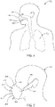
- FIG. 1 a schematic view is shown of a patient 100 showing portions of respiratory pathways.
- Air can be inspired through the nose 108 and into nasal passages 104 or through the mouth 110 and into oral passages 106 eventually reaching the lungs 102.
- the inspired air is warmed, humidified, and picks up volatile organic compounds during its passage to the lungs, while it remains in the lungs, and further during expiration on its way back out of the lungs.
- the air is then expired through the nasal passages 104 and out the nose 108 and/or through oral passages 106 and out the mouth 110.
- a breath sampling mask is included which can aid in one or more of: capturing breath samples, controlling how the breath samples are generated and treated, and providing additional data regarding the patient and/or their current physiological state.
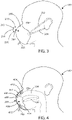
- FIG. 2 is a schematic view of a breath sampling mask 200 as worn by a patient 100 in accordance with various embodiments herein.
- the breath sampling mask 200 can include one or more elastic members 202, 204 configured to secure the breath sampling mask 200 to the patient's face.
- the pressure of the breath sampling mask 200 on the face can aid in forming an air tight connection of the breath sampling mask 200 to the patient's face.
- the breath sampling mask 200 when the patient creates a negative pressure inside the breath sampling mask 200, air can be drawn from the ambient environment into the breath sampling mask 200 through the exterior surface of breath sampling mask 200 (or a portion thereof), as indicated in FIG. 2 by air inflow arrows 210, 212, 214, and 216.
- the breath sampling mask 200, or portions thereof can be made of a porous material (one or more layers of material) to allow air to be drawn in, in this way.
- Porous materials can include, but are not limited to, woven and nonwoven fibrous materials, porous cellulosic materials, porous polymers, porous or non-porous materials assuming porous structures such as grids, weaves, sieves, and the like.
- the breath sampling mask 200 can be made of a non-porous material.
- Non-porous materials can include, but are not limited to, polymers, metals, cellulosic materials, composites, metals, ceramics, and the like.
- breath sampling mask 200 can include filters or conditioned surfaces to treat the incoming air such that it can do one or more of: filtering particulate matter from the air, providing humidity control, providing a filter for organic or inorganic matter, and providing for adsorption of compounds and/or particulates in the ambient environment.
- a carbon surface can be included on the exterior to filter out environmental particulates and/or environmental volatile organic compounds (VOCs).
- VOCs environmental volatile organic compounds
- a carbon material can be sprayed on, or otherwise applied to, an outer surface of the breath sampling mask 200.
- the breath sampling mask 200 can include a carbon layer disposed within the mask itself.
- a carbon material can be integrated into a material layer used to make the breath sampling mask 200 and/or sandwiched in between layers of material used to make the breath sampling mask 200.
- Carbon herein can be specifically be carbon that can absorb significant amounts of VOCs through high surface area such as activated carbon or activated charcoal (in some cases one gram of activated carbon has a surface area in excess of 3,000 m 2 or more) and/or through the use of chemical treatments to enhance absorption properties.
- the breath sampling mask 200 can include various ports or conduits in and out of the breath sampling mask 200, some of which may be in fluid communication with valves or other components or portions of the breath sampling mask 200.
- the breath sampling mask 200 can include one or more conduits 206, which can serve as a passageway for breath samples, exhaust air, wires, or the like.
- FIG. 3 is a schematic view of a breath sampling mask 200 as worn by a patient 100 in accordance with various embodiments herein.
- the breath sampling mask 200 can include one or more elastic members 202, 204 configured to secure the breath sampling mask 200 to the patient's face.
- the breath sampling mask 200 can include various ports or conduits in and out of the breath sampling mask 200, some of which may be in fluid communication with valves or other components or portions of the breath sampling mask 200.
- the breath sampling mask 200 can include an air intake port 308.
- the breath sampling mask 200 can also include one or more conduits 206, which can serve as a passageway for breath samples, exhaust air, wires, or the like.
- a preconditioning unit (not shown) can be connected to an air intake port 308 via a suitable connector, such as a bayonet connector.
- Pre-conditioning and/or filtering the inhaled air can include, but not be limited to, providing humidity control, providing temperature control, filtering particulate matter from the air, filtering organic or inorganic matter, including VOCs, by providing for adsorption and/or absorption of compounds and/or particulates from the ambient environment.
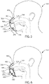
- the breath sampling mask 200 includes a mask housing 402 that is configured to cover a portion of the face of the patient 100.
- the mask housing 402 can define an interior chamber 406, which can be a breath receiving chamber.
- the breath sampling mask 200 can also include a nose clip member 404 connected to the mask housing 402 for helping to secure the breath sampling mask 200 to the patient 100.
- the nose clip member 404 can work in collaboration with the elastic members 202, 204, to form an air tight connection of the breath sampling mask 200 against the patient's face.
- breath sampling mask 200 can include a gas outflow conduit 206 in fluid communication with the breath receiving chamber.
- the nose clip member 404 can take on various forms and be make of various materials.
- the nose clip member 404 can include a U-shaped or V-shaped member which can exert at least some pressure on a patient's nose from two-directions that are at least partially opposed.
- the nose clip member 404 can include a spring-like element which can expand under applied force to allow the nose clip member to fit over a patient's nose, but then exert pressure on the nose when the applied force is released.
- Materials used to form the nose clip member 404 can include, but are not limited to, polymers, metals, composites, and the like.
- the breath sampling mask 200 can include a one-way airflow valve 408.
- the one-way airflow valve 408 can be in fluid communication between the air intake port 308 and the interior chamber 406, the one-way airflow valve 408 only allowing a flow of air from the area outside of the mask housing 402 into the interior chamber 406.
- a filter can be placed in fluid communication with one-way airflow valve 408 such that it can remove particulate or chemical impurities from the environmental air prior to being inhaled by patient 100.
- the filter can be integrated with the valve 408 structure.
- the filter can do one or more of filter out particulate matter from inspired air, provide humidity control, provide a filter for organic or inorganic matter, and/or provide for adsorption of compounds and/or particulates in the ambient environment.
- the filter can include a carbon material, such as those described above, to filter out environmental particulates and/or environmental volatile organic compounds (VOCs).
- the breath sampling mask 200 can include a sensor 410 that can be connected to the nose clip member 404.
- the sensor 410 can be configured to contact the skin of the patient 100 when the mask housing 402 is worn by the patient 100.
- the sensor 410 can be selected from a group including a temperature sensor, a heart rate sensor, and a blood pressure sensor.
- the sensor 410 in FIG. 4 is shown as being connected to the nose clip member 404 and in contact with the skin of the patient, other embodiments for the sensor 410 can be contemplated.
- the sensor 410 can include an ear clip sensor, a fingertip sensor, a carotid artery sensor, or a galvanic skin sensor that is not integral with the mask, but connected to the mask housing via a wired or wireless connection.
- the sensor 410 can include non-contact sensors (e.g., that does not contact the skin), such as those used in electromagnetic-based, laser-based, and image-based sensor systems.
- the breath sampling mask 200 can also include additional sensors 412, 414, which can be on the outside of the breath sampling mask 200 or on the inside of the breath sampling mask 200.
- Exemplary sensors can include an ambient temperature sensor, an ambient humidity sensor, an internal temperature sensor, and an internal humidity sensor.
- FIG. 4 shows a single chamber inside the mask
- other embodiments of masks herein can include multiple chambers that are isolated from one another.
- the mask can be configured to allow air and breath samples to move through the chambers of the mask in only a particular way or direction.
- FIG. 5 is a schematic cutaway view of a breath sampling mask 200 as worn by a patient in accordance with various embodiments herein.
- the breath receiving chamber includes dividing wall 506 to isolate breath receiving chamber into a nasal chamber 502 and a mouth chamber 504, as defined by the mask housing 402.
- the nasal chamber 502 and the mouth chamber 504 can be separated from one another when the breath sampling mask 200 comes into contact with the face of patient during usage.
- the one-way airflow valve 408 only allows a flow of air from the area outside of the mask housing 402 into the nasal chamber 502 through air intake port 308.
- another one-way airflow valve 508 only allows a flow of air from the mouth chamber 504 out through conduit 206. In this manner, air only moves through the chambers of the breath sampling mask 200 in one direction.
- breath sampling mask 200 can include a gas outflow conduit 206 in fluid communication with the nasal chamber 502, the mouth chamber 504, or both.
- a container can be used to hold a breath sample, and the container itself can be disposed in the breath sampling mask 200 or otherwise in fluid communication with the breath sampling mask 200.
- FIG. 6 a schematic cutaway view of a breath sampling mask 200 as worn by a patient 100 is shown in accordance with various embodiments herein.
- a breath sample container 602 is disposed within the mouth chamber 504.
- the breath sample container 602 can define an interior volume 604 in order to hold and retain a breath sample. It will be appreciated that while the breath sample container 602 shown in FIG. 6 is removable, in another embodiment, breath sample container 602 could be an integral part of the breath sampling mask 200.
- Breath sampling masks in accordance with embodiments herein can form parts of breath sampling systems.
- breath sampling systems can include a breath sampling mask along with other components such as chemical sensors including sensing elements and circuitry for generating signals based on electrical properties of the sensing elements.
- FIG. 7 a schematic view is shown of a breath sampling system 700 in accordance with various embodiments herein.
- the breath sampling system 700 can include breath sampling mask 200, which can be worn by a patient 100.
- breath sampling mask 200 can be worn by a patient 100.
- air can be inspired into a nasal chamber 502 and into the lungs of the patient 100. This air can then be expired out into a mouth chamber 504 before passing out through conduit 206 and on to a gaseous analyte sensing device 702 for analysis.
- the gaseous analyte sensing device 702 can include a housing 718.
- the gaseous analyte sensing device 702 can be connected to breath sampling mask 200 via conduit 206, through which a patient's gaseous breath sample can travel to be evaluated at gaseous analyte sensing device 702.
- the patient's gaseous breath sample can pass through an evaluation sample (patient sample) input port 704.
- the gaseous analyte sensing device 702 can also include a control sample (environment) input port 706.
- the gaseous analyte sensing device 702 can also include a chemical sensor element chamber 708, into which a chemical sensor element can be placed.
- the gaseous analyte sensing device 702 can also include a display screen 710 and a user input device 712, such as a keyboard.
- the gaseous analyte sensing device 702 can also include a gas outflow port 714.
- the gaseous analyte sensing device 702 can also include flow sensors in fluid communication with the gas flow associated with one or more of the evaluation sample input port 704 and control sample input port 706. It will be appreciated that many different types of flow sensors can be used.
- a hot-wire anemometer can be used to measure the flow of air.
- the gaseous analyte sensing device 702 can include a CO 2 sensor in fluid communication with the gas flow associated with one or more of the evaluation sample input port 704 and control sample input port 706.
- the gaseous analyte sensing device 702 can also include other functional components.
- the gaseous analyte sensing device 702 can include a humidity control module 716 and/or a temperature control module 720.
- the humidity control module 716 can be in fluid communication with the gas flow associated with one or more of the evaluation sample input port 704 and control sample input port 706 in order to adjust the humidity of one or both gas flow streams in order to make the relative humidity of the two streams substantially the same in order to prevent an adverse impact on the readings obtained by the system.
- the temperature control module 720 can be in fluid communication with the gas flow associated with one or more of the evaluation sample input port 704 and control sample input port 706 in order to adjust the temperature of one or both gas flow streams in order to make the temperature of the two streams substantially the same in order to prevent an adverse impact on the readings obtained by the system.
- the air flowing into the control sample input port can be brought up to 37 degrees Celsius in order to match the temperature of air coming from a patient.
- the humidity control module and the temperature control module can be upstream from the input ports, within the input ports, or downstream from the input ports in the housing 718 of the gaseous analyte sensing device 702. In some embodiments, the humidity control module 716 and the temperature control module 720 can be integrated.
- breath samples can be put into contact with a chemical sensor element in the mask itself or in a structure directly attached to the mask.
- One or more components of the gaseous analyte sensing device 702 shown in reference to FIG. 7 can be integrated into the breath sampling mask 200. As such, in some embodiments, a separate gaseous analyte sensing device may not be needed in a breath sensing system.
- FIG. 8 a schematic view is shown of a breath sampling system 800 in accordance with various embodiments herein.
- the breath sampling system 800 can include a breath sampling mask 200 including a nasal chamber 502 and a mouth chamber 504.
- a chemical sensor holder 802 can be disposed within a breath receiving chamber, such as mouth chamber 504.
- the chemical sensor holder 802 can be configured to allow removable mounting of a chemical sensor element.
- the chemical sensor element can interface with a breath sample collected through the breath sampling mask 200 when the patient 100 exhales into the breath sampling mask 200. Exemplary chemical sensor elements will be described more fully below in reference to FIGS. 18-21 .
- Sample gas can optionally pass through a structure 806 such as a filter or valve and into the chemical sensor holder 802. After entering the chemical sensor holder 802, the gas can then pass out of the system through an exhaust port 804.
- Measurement circuitry (not shown in this view) can be associated with the chemical sensor holder 802 in order to generate a signal based on an electrical property of the chemical sensor element.
- the signal(s) can be conveyed to an analysis device 810 through a data conduit 808. It will be appreciated, however, that signals can also be conveyed wirelessly.
- FIG. 9 a schematic view is shown of a breath sampling system 900 in accordance with various embodiments herein.
- the breath sampling system 900 includes communication circuitry and an antenna 902 in order to generate wireless signals that can be received by an analysis device 810.
- the chemical sensor holder 802 can be housed in a separate structure that can be attached (removably or not) to the breath sampling mask 200.
- FIG. 10 a schematic view is shown of a breath sampling system 1000 in accordance with various embodiments herein.
- a chemical sensor holder housing 1002 is included.
- the chemical sensor holder housing can be in fluid communication with the breath receiving chamber.
- Sample gas can pass from the mouth chamber 504 into chemical sensor holder housing 1002 and, specifically, into the chemical sensor holder 802 located within the chemical sensor holder housing 1002. Sample gas can pass over chemical sensor element (not shown), secured by chemical sensor holder 802, and out exhaust port 804.
- the breath sampling system 1100 can include breath sampling mask 200, which can be worn by a patient 100.
- Breath sampling mask 200 can include nose clip member 404 for helping to secure the breath sampling mask 200 to the patient 100.
- air can be inspired into the mask and into the lungs of the patient 100. This air can then be expired out into a mouth chamber before passing out through conduit 206 and on to a gaseous analyte sensing device 702.
- the breath sampling mask 200 and gaseous analyte sensing device 702 can be connected directly via a data conduit, such as data conduit 808 shown in FIG. 8 . In other embodiments, the breath sampling mask 200 and gaseous analyte sensing device 702 can be connected wirelessly.
- Breath sampling mask 200 can include air intake port 308 that can be in fluid communication with a one-way airflow valve on the interior (not shown) of the breath sampling mask 200.
- the breath sampling mask 200 can include one or more elastic members 202 and 204 configured to secure the breath sampling mask 200 to the patient's face.
- the breath sampling mask 200 can include various ports or conduits in and out of the breath sampling mask 200, some of which may be in fluid communication with valves, filters, or other components or portions of the breath sampling mask 200.
- the breath sampling mask 200 can include one or more conduits 206, which can serve as a passageway for breath samples, exhaust air, wires, or the like.
- conduits 206 can serve as a passageway for breath samples, exhaust air, wires, or the like.
- Like structures of breath sampling mask 200 are shown in a schematic isometric view in FIG. 13 and in a schematic top plan view in FIG. 14 .
- Breath sampling mask 200 can include nose clip member 404 attached to mask housing 402.
- one or more sensors 410 can be connected to the nose clip member 404, the one or more sensors 410 configured to contact the skin of the patient 100 when the breath sampling mask 200 is worn by the patient 100.
- the sensor 410 can be selected from a group including a temperature sensor, a heart rate sensor, and a blood pressure sensor.
- Breath sampling mask 200 can also include a nasal chamber 502 and a mouth chamber 504.
- Nasal chamber 502 and mouth chamber 504 can be separated by a dividing wall 506. It will be appreciated that in some embodiments the nasal chamber 502 defines the breath receiving chamber, while in other embodiments the mouth chamber can define the breath receiving chamber. In some embodiments, both the nasal chamber 502 and the mouth chamber can define the breath receiving chamber. In some embodiments, breath sampling mask 200 does not have a dividing wall 506.
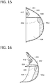
- Mouth chamber 504 can include a dividing member 1502 that can span at least a portion of mouth chamber 504 without completely dividing mouth chamber 504 into more than one section. Attached to dividing member 1502 can be a chemical sensor holder 802. Chemical sensor holder 802 can serve as an anchor point to secure a chemical sensor element (not shown) within the interior, or patient-facing side, of breath sampling mask 200.
- breath sampling mask 200 can include a one-way airflow valve 408 that can be in fluid communication with a one-way airflow valve on the exterior (not shown) of the breath sampling mask 200.
- the chemical sensor element 1800 can include a substrate 1802.
- the substrate can be formed from many different materials.
- the substrate can be formed from polymers, metals, glasses, ceramics, cellulosic materials, composites, metal oxides, and the like.
- the thickness of the substrate can vary.
- the substrate has sufficient structural integrity to be handled without undue flexure that could damage components thereon.
- the substrate can have a thickness of about 0.05 mm to about 5 mm.
- the length and width of the substrate can also vary.
- the length (or major axis) can be from about 0.2 cm to about 10 cm. In some embodiments, the width (perpendicular to the major axis) can be from about 0.2 cm to about 8 cm.
- the chemical sensor element can be disposable. In some embodiments, the chemical sensor element can be reusable.
- the chemical sensor element can include a first measurement zone 1804 disposed on the substrate 1802.
- the first measurement zone 1804 can define a portion of a first gas flow path.
- the first measurement zone (or breath sample zone) 1804 can include a plurality of discrete binding detectors that can sense analytes in a gaseous sample, such as a breath sample.
- a second measurement zone (or environment sample zone) 1806, separate from the first measurement zone 1804, can also be disposed on the substrate 1802.
- the second measurement zone 1806 can also include a plurality of discrete binding detectors.
- the second measurement zone 1806 can include the same (in type and/or number) discrete binding detectors that are within the first measurement zone 1804.
- the second measurement zone 1806 can include only a subset of the discrete binding detectors that are within the first measurement zone 1804.
- the data gathered from the first measurement zone which can be reflective of the gaseous sample analyzed, can be corrected or normalized based on the data gathered from the second measurement zone, which can be reflective of analytes present in the environment.
- both a first and second measurement zone can reflect the breath sample analyzed.
- a second measurement zone is not included.
- a third measurement zone (drift control or witness zone) 1808 can also be disposed on the substrate.
- the third measurement zone 1808 can include a plurality of discrete binding detectors.
- the third measurement zone 1808 can include the same (in type and/or number) discrete binding detectors that are within the first measurement zone 1804.
- the third measurement zone 1808 can include only a subset of the discrete binding detectors that are within the first measurement zone 1804.
- the third measurement zone 1808 can include discrete binding detectors that are different than those of the first measurement zone 1804 and the second measurement zone 1806.
- a third measurement zone 1808 is not included. Aspects of the third measurement zone are described in greater detail below.
- the first measurement zone, the second measurement zone, and the third measurement zone can be the same size or can be of different sizes.
- the chemical sensor element 1800 can also include a component 1810 to store reference data.
- the component 1810 to store reference data can be an electronic data storage device, an optical data storage device, a printed data storage device (such as a printed code), or the like.
- the reference data can include, but is not limited to, data regarding the third measurement zone.
- chemical sensor elements embodied herein can include electrical contacts (not shown) that can be used to provide power to components on the chemical sensor element 1800 and/or can be used to read data regarding the measurement zones and/or data from the stored in component 1810. However, in other embodiments there are no external electrical contacts on the chemical sensor element 1800.
- Chemical sensor element 1800 can be configured to fit within chemical sensor holder 802, shown in FIGS. 8-10 and 15-17 . Further aspects of exemplary chemical sensor elements can be found in U.S. App. No. 14/883,895 , the content of which is herein incorporated by reference in its entirety.
- circuits can be used to gather data from chemical sensor elements. It will be appreciated that the chemical sensor elements embodied herein can include those that are compatible with passive wireless sensing techniques.
- One example of a passive sensor circuit 2202 and a portion of a reading circuit 2222 is illustrated schematically in FIG. 22 and discussed in more detail below, however, many other circuits are contemplated herein.
- a plurality of discrete binding detectors 1902 can be disposed within the measurement zone 1900 in an array.
- a chemical sensor element can include a plurality of discrete binding detectors configured in an array within a measurement zone.
- the plurality of discrete binding detectors can be identical, while in other embodiments the plurality of discrete binding detectors can be different from one another.
- the discrete binding detectors can be heterogeneous in that they are all different from one another in terms of their binding behavior or specificity with regard a particular analyte. In some embodiments, some discrete binding detectors can be duplicated for validation purposes, but are otherwise heterogeneous from other discrete binding detectors. Yet in other embodiments, the discrete binding detectors can be homogeneous. While the discrete binding detectors 1902 of FIG.
- the discrete binding detectors can take on many different shapes (including, but not limited to, various polygons, circles, ovals, irregular shapes, and the like) and, in turn, the groups of discrete binding detectors can be arranged into many different patterns (including, but not limited to, star patterns, zig-zag patterns, radial patterns, symbolic patterns, and the like).
- the order of specific discrete binding detectors 1902 across the length 1912 and width 1914 of the measurement zone can be substantially random. In other embodiments, the order can be specific. For example, in some embodiments, a measurement zone can be ordered so that the specific discrete binding detectors 1902 for analytes having a lower molecular weight are located farther away from the incoming gas flow relative to specific discrete binding detectors 1902 for analytes having a higher molecular weight which are located closer to the incoming gas flow. As such, chromatographic effects which may serve to provide separation between chemical compounds of different molecular weight can be taken advantage of to provide for optimal binding of chemical compounds to corresponding discrete binding detectors.
- the number of discrete binding detectors within a particular measurement zone can be from about 1 to about 100,000. In some embodiments, the number of discrete binding detectors can be from about 1 to about 10,000. In some embodiments, the number of discrete binding detectors can be from about 1 to about 1,000. In some embodiments, the number of discrete binding detectors can be from about 2 to about 500. In some embodiments, the number of discrete binding detectors can be from about 10 to about 500. In some embodiments, the number of discrete binding detectors can be from about 50 to about 500. In some embodiments, the number of discrete binding detectors can be from about 1 to about 250. In some embodiments, the number of discrete binding detectors can be from about 1 to about 50.
- each of the discrete binding detectors suitable for use herein can include at least a portion of one or more electrical circuits.
- each of the discrete binding detectors can include one or more passive electrical circuits.
- the graphene varactors can be included such that they are integrated directly on an electronic circuit.
- the graphene varactors can be included such that they are wafer bonded to the circuit.
- the graphene varactors can include integrated readout electronics, such as a readout integrated circuit (ROIC).
- ROIC readout integrated circuit
- the discrete binding detectors embodied herein can include graphene-based variable capacitors (or graphene varactors).
- graphene-based variable capacitors or graphene varactors.
- FIG. 20 a schematic view of a graphene varactor 2000 is shown in accordance with the embodiments herein. It will be appreciated that graphene varactors can be prepared in various ways with various geometries, and that the graphene varactor shown in FIG. 20 is just one example in accordance with the embodiments herein.
- Graphene varactor 2000 can include an insulator layer 2002, a gate electrode 2004 (or "gate contact"), a dielectric layer (not shown in FIG. 20 ), one or more graphene layers, such as graphene layers 2008 a and 2008b, and a contact electrode 2010 (or "graphene contact”).
- the graphene layer(s) 2008 a-b can be contiguous, while in other embodiments the graphene layer(s) 2008 a-b can be non-contiguous.
- Gate electrode 2004 can be deposited within one or more depressions formed in insulator layer 2002.
- Insulator layer 2002 can be formed from an insulative material such as silicon dioxide, formed on a silicon substrate (wafer), and the like.
- Gate electrode 2004 can be formed by an electrically conductive material such as chromium, copper, gold, silver, tungsten, aluminum, titanium, palladium, platinum, iridium, and any combinations or alloys thereof, which can be deposited on top of or embedded within the insulator layer 2002.
- the dielectric layer can be disposed on a surface of the insulator layer 2002 and the gate electrode 2004.
- the graphene layer(s) 2008 a-b can be disposed on the dielectric layer. The dielectric layer will be discussed in more detail below in reference to FIG. 21 .
- Graphene varactor 2000 includes eight gate electrode fingers 2006 a -2006 h . It will be appreciated that while graphene varactor 2000 shows eight gate electrode fingers 2006 a -2006 h , any number of gate electrode finger configurations can be contemplated. In some embodiments, an individual graphene varactor can include fewer than eight gate electrode fingers. In some embodiments, an individual graphene varactor can include more than eight gate electrode fingers. In other embodiments, an individual graphene varactor can include two gate electrode fingers. In some embodiments, an individual graphene varactor can include 1, 2, 3, 4, 5, 6, 7, 8, 9, 10, or more gate electrode fingers.
- Graphene varactor 2000 can include one or more contact electrodes 2010 disposed on portions of the graphene layers 2008 a and 2008b.
- Contact electrode 2010 can be formed from an electrically conductive material such as chromium, copper, gold, silver, tungsten, aluminum, titanium, palladium, platinum, iridium, and any combinations or alloys thereof. Further aspects of exemplary graphene varactors can be found in U.S. Pat. No. 9,513,244 , the content of which is herein incorporated by reference in its entirety.
- the graphene varactor 2100 can include an insulator layer 2002 and a gate electrode 2004 recessed into the insulator layer 2002.
- the gate electrode 2004 can be formed by depositing an electrically conductive material in the depression in the insulator layer 2002, as discussed above in reference to FIG. 20 .
- a dielectric layer 2102 can be formed on a surface of the insulator layer 2002 and the gate electrode 2004.
- the dielectric layer 2102 can be formed of a material, such as, silicon dioxide, aluminum oxide, hafnium dioxide, zirconium dioxide, hafnium silicate, or zirconium silicate.
- the graphene varactor 2100 can include a single graphene layer 2104 that can be disposed on a surface of the dielectric layer 2102.
- the graphene layer 2104 can be surface-modified with a modification layer 2106. It will be appreciated that in some embodiments, the graphene layer 2104 is not surface-modified.
- the breath sensing systems described herein can include circuitry for generating signals from the discrete binding detectors. Such circuitry can include active and passive sensing circuits. Such circuitry can implement wired (direct electrical contact) or wireless sensing techniques.
- FIG. 22 a schematic diagram of a passive sensor circuit 2202 and a portion of a reading circuit 2222 is shown in accordance with various aspects herein.
- the passive sensor circuit 2202 can include a metal-oxide-graphene varactor 2204 (wherein RS represents the series resistance and CG represents the varactor capacitor) coupled to an inductor 2210.
- the reading circuit 2222 can include a reading coil having a resistance 2224 and an inductance 2226.
- FIG. 22 are merely one approach. Many different approaches are contemplated herein.
- a method of determining the presence of one or more disease states in a patient is included.
- the method can include putting a breath sampling mask on a patient and alerting the patient to breathe in and out to generate a breath sample.
- the method can include contacting the breath sample with a chemical sensor element.
- the method can further include collecting data from chemical sensor element comprising a plurality of discrete binding detectors.
- the method can further include using a measurement circuit to generate signals from the discrete binding detectors.
- the method can further include evaluating the signals by comparing them to previously obtained sets of signals or signal patterns.
- the method can include alerting the patient to breathe in through the nose and out through the mouth to generate a breath sample. In some embodiments, the method can include instructing the patient to breathe in through the mouth and out through the mouth. In some embodiments, the method can include instructing the patient to breathe in through the mouth and out through the nose. In yet other embodiments, the method can include instructing the patient to breathe in through the nose and out through the nose.
- the method can include evaluating the signals by comparing them to previously obtained sets of signals or patterns for patients in a non-diseased or diseased state.
- the diseased state can include, but not be limited to cancer, including lung cancer, blood-borne cancers, prostate cancer, rectal cancer, breast cancer, liver cancer, pancreatic cancer, chronic obstructive pulmonary disease, diabetes, heart failure, and the like.
- the comparison can include detecting patterns of differentiation between non-diseased and diseased states.
- the method can include detecting one or more volatile organic compounds in the breath of a patient.
- the phrase “configured” describes a system, apparatus, or other structure that is constructed or configured to perform a particular task or adopt a particular configuration to.
- the phrase “configured” can be used interchangeably with other similar phrases such as arranged and configured, constructed and arranged, constructed, manufactured and arranged, and the like.
Landscapes
- Health & Medical Sciences (AREA)
- Life Sciences & Earth Sciences (AREA)
- Surgery (AREA)
- Animal Behavior & Ethology (AREA)
- Pathology (AREA)
- Engineering & Computer Science (AREA)
- Biomedical Technology (AREA)
- Heart & Thoracic Surgery (AREA)
- Medical Informatics (AREA)
- Molecular Biology (AREA)
- Physics & Mathematics (AREA)
- Biophysics (AREA)
- General Health & Medical Sciences (AREA)
- Public Health (AREA)
- Veterinary Medicine (AREA)
- Physiology (AREA)
- Cardiology (AREA)
- Pulmonology (AREA)
- Investigating Or Analysing Biological Materials (AREA)
- Sampling And Sample Adjustment (AREA)
Abstract
Description
- This application is being filed as a PCT International Patent application on February 20, 2019, in the name of the REGENTS OF THE UNIVERSITY OF MINNESOTA, applicant for the designation of all countries and Arthur Guy Erdman, a U.S. Citizen, and Gregory Kermit Peterson, a U.S. Citizen, inventors for the designation of all countries. This application is also being filed as PCT International Patent application in the name of Boston Scientific Scimed, Inc., a U.S. national corporation, applicant for the designation of all countries and Gregory J. Sherwood, a U.S. Citizen, Justin Theodore Nelson, a U.S. Citizen and Michael Mathias Freking, a U.S. Citizen, inventors for the designation of all countries. This application claims priority to
U.S. Provisional Application No. 62/632,552 filed February 20, 2018 - The present application relates to a breath sampling mask and systems and methods related to the same.
- The accurate detection of diseases can allow clinicians to provide appropriate therapeutic interventions. The early detection of diseases can lead to better treatment outcomes. Diseases can be detected using many different techniques including analyzing tissue samples, analyzing various bodily fluids, diagnostic scans, genetic sequencing, and the like.
- Some disease states result in the production of specific chemical compounds. In some cases, volatile organic compounds (VOCs) released into a gaseous sample of a patient can be hallmarks of certain diseases. The detection of these compounds or differential sensing of the same can allow for the early detection of particular disease states.
- The breath of a patient provides an ideal gas for diagnostic sampling purposes. As a part of tidal respiration, air is drawn in through the nose and/or mouth and into the lungs. By its presence in close contact with moist internal tissues, the inspired air is warmed, humidified, and picks up volatile organic compounds. This air is then expired out through the nose and/or mouth.
- In a first aspect, a breath sensing system is included. The breath sampling system can include a breath sampling mask. The breath sampling mask can include a mask housing configured to cover a portion of the face of a patient, the mask housing defining a breath receiving chamber. The breath sampling system can also include a chemical sensor element in fluid communication with the breath sampling mask. The chemical sensor element can include a plurality of discrete binding detectors. The chemical sensor element can be configured to interface with a breath sample collected through the breath sampling mask.
- In a second aspect, in addition to one or more of the preceding or following aspects, or in the alternative to some aspects, the breath sensing system can include circuitry for generating signals from the discrete binding detectors.
- In a third aspect, in addition to one or more of the preceding or following aspects, or in the alternative to some aspects, the breath sensing system can include a breath sampling mask including a nose clip for helping to secure the breath sampling mask to the face of a patient.
- In a fourth aspect, in addition to one or more of the preceding or following aspects, or in the alternative to some aspects, the breath sensing system can include a sensor such as one or more of a temperature sensor, a heart rate sensor, and a blood pressure sensor.
- In a fifth aspect, in addition to one or more of the preceding or following aspects, or in the alternative to some aspects, the breath sensing system can include a sensor such as one or more of an ambient temperature sensor, an ambient humidity sensor, an internal temperature sensor, and an internal humidity sensor.
- In a sixth aspect, in addition to one or more of the preceding or following aspects, or in the alternative to some aspects, the breath sensing system can include a removable breath sample container disposed within the mouth chamber.
- In a seventh aspect, in addition to one or more of the preceding or following aspects, or in the alternative to some aspects, the breath sensing system can include a gas outflow conduit in fluid communication with the breath receiving chamber.
- In an eighth aspect, in addition to one or more of the preceding or following aspects, or in the alternative to some aspects, the breath sensing system can include a chemical sensor holder configured to allow removable mounting of a chemical sensor element.
- In a ninth aspect, in addition to one or more of the preceding or following aspects, or in the alternative to some aspects, the chemical sensor holder can be disposed within the breath receiving chamber.
- In a tenth aspect, in addition to one or more of the preceding or following aspects, or in the alternative to some aspects, the breath sensing system can include a chemical sensor holder housing in fluid communication with the breath receiving chamber, wherein the chemical sensor element can be disposed within the chemical sensor holder housing.
- In an eleventh aspect, in addition to one or more of the preceding or following aspects, or in the alternative to some aspects, the breath sensing system can include a filter in fluid communication with the one-way airflow valve.
- In a twelfth aspect, in addition to one or more of the preceding or following aspects, or in the alternative to some aspects, a breath sampling mask is included. The breath sampling mask can include a mask housing configured to cover a portion of the face of a patient. The mask housing can define a chamber. The mask configured to remove volatile organic compounds from air drawn in through the mask housing.
- In a thirteenth aspect, in addition to one or more of the preceding or following aspects, or in the alternative to some aspects, the breath sampling mask can include a sensor such as one or more of a temperature sensor, a heart rate sensor, and a blood pressure sensor.
- In a fourteenth aspect, in addition to one or more of the preceding or following aspects, or in the alternative to some aspects, the breath sampling mask can include a nose clip member for helping to secure the breath sampling mask to the patient.
- In a fifteenth aspect, in addition to one or more of the preceding or following aspects, or in the alternative to some aspects, a sensor can be attached to a nose clip member.
- In a sixteenth aspect, in addition to one or more of the preceding or following aspects, or in the alternative to some aspects, the mask housing of the breath sampling mask can include a dividing wall isolating the chamber into a nasal chamber and a mouth chamber.
- In a seventeenth aspect, in addition to one or more of the preceding or following aspects, or in the alternative to some aspects, the breath sampling mask can include a one-way airflow valve in fluid communication with the nasal chamber and an area outside of the mask housing, where the one-way airflow valve only allows a flow of air from the area outside of the mask housing into the nasal chamber.
- In an eighteenth aspect, in addition to one or more of the preceding or following aspects, or in the alternative to some aspects, the breath sampling mask can include a chemical sensor holder configured to allow removable mounting of a chemical sensor element. The chemical sensor holder can be disposed within the mouth chamber of the breath sampling mask.
- In a nineteenth aspect, in addition to one or more of the preceding or following aspects, or in the alternative to some aspects, the breath sampling mask can include a sensor such as one or more of an ambient temperature sensor, an ambient humidity sensor, an internal temperature sensor, and an internal humidity sensor.
- In a twentieth aspect, in addition to one or more of the preceding or following aspects, or in the alternative to some aspects, a method of determining the presence of one or more disease states of a patient is included. The method can include putting a breath sampling mask on a patient; alerting the patient to breathe in and out to generate a breath sample; contacting the breath sample with a chemical sensor element, the chemical sensor element including a plurality of discrete binding detectors; using a measurement circuit to generate signals from the discrete binding detectors; and evaluating the signals by comparing them to previously obtained sets of signals or signal patterns.
- This summary is an overview of some of the teachings of the present application and is not intended to be an exclusive or exhaustive treatment of the present subject matter. Further details are found in the detailed description and appended claims. Other aspects will be apparent to persons skilled in the art upon reading and understanding the following detailed description and viewing the drawings that form a part thereof, each of which is not to be taken in a limiting sense. The scope of the present application is defined by the appended claims and their legal equivalents.
- The technology may be more completely understood in connection with the following drawings, in which:
-
FIG. 1 is a schematic view of a patient showing portions of respiratory pathways. -
FIG. 2 is a schematic view of a breath sampling mask as worn by a patient in accordance with various embodiments herein. -
FIG. 3 is a schematic view of a breath sampling mask as worn by a patient in accordance with various embodiments herein. -
FIG. 4 is a schematic cutaway view of a breath sampling mask as worn by a patient in accordance with various embodiments herein. -
FIG. 5 is a schematic cutaway view of a breath sampling mask as worn by a patient in accordance with various embodiments herein. -
FIG. 6 is a schematic cutaway view of a breath sampling mask as worn by a patient in accordance with various embodiments herein. -
FIG. 7 is a schematic view of a breath sampling system in accordance with various embodiments herein. -
FIG. 8 is a schematic view of a breath sampling system in accordance with various embodiments herein. -
FIG. 9 is a schematic view of a breath sampling system in accordance with various embodiments herein. -
FIG. 10 is a schematic view of a breath sampling system in accordance with various embodiments herein. -
FIG. 11 is a schematic view of a breath sampling system in accordance with various embodiments herein. -
FIG. 12 is a schematic view of a breath sampling mask in accordance with various embodiments herein. -
FIG. 13 is a schematic view of a breath sampling mask in accordance with various embodiments herein. -
FIG. 14 is a schematic view of a breath sampling mask in accordance with various embodiments herein. -
FIG. 15 is a schematic cutaway view of a breath sampling mask in accordance with various embodiments herein. -
FIG. 16 is a schematic isometric view of a breath sampling mask in accordance with various embodiments herein. -
FIG. 17 a schematic bottom plan view of a breath sampling mask in accordance with various embodiments herein. -
FIG. 18 a schematic top plan view of a chemical sensor element in accordance with various embodiments herein. -
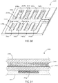
FIG. 19 is a schematic diagram of a portion of a measurement zone in accordance with various embodiments herein. -
FIG. 20 is a schematic perspective view of a graphene varactor in accordance with various embodiments herein. -
FIG. 21 is a schematic cross-sectional view of a portion of a graphene varactor in accordance with various embodiments herein. -
FIG. 22 is a circuit diagram of a passive sensor circuit and a portion of a reading circuit is shown in accordance with various embodiments herein. - While the technology is susceptible to various modifications and alternative forms, specifics thereof have been shown by way of example and drawings, and will be described in detail. It should be understood, however, that the application is not limited to the particular embodiments described. On the contrary, the application is to cover modifications, equivalents, and alternatives falling within the spirit and scope of the technology.
- The breath of a patient provides an ideal gas for diagnostic sampling purposes. As a part of tidal respiration, air is drawn in through the nose and/or mouth and into the lungs. By its presence in close contact with moist internal tissues, the inspired air is warmed, humidified, and picks up volatile organic compounds (VOCs). This air is then expired out through the nose and/or mouth.
- In some instances, the VOCs present in exhaled breath can be hallmarks of certain diseases, including but not limited to cancers, including lung cancer, blood-borne cancers, prostate cancer, rectal cancer, breast cancer, liver cancer, pancreatic cancer, or to other disorders such as chronic obstructive pulmonary disease, diabetes, heart failure, and the like. Detection of VOCs in the breath of a patient directly from the gaseous form can provide an accurate mechanism for determining one or more diseased states.
- Referring now to
FIG. 1 , a schematic view is shown of apatient 100 showing portions of respiratory pathways. Air can be inspired through thenose 108 and intonasal passages 104 or through themouth 110 and intooral passages 106 eventually reaching thelungs 102. The inspired air is warmed, humidified, and picks up volatile organic compounds during its passage to the lungs, while it remains in the lungs, and further during expiration on its way back out of the lungs. The air is then expired through thenasal passages 104 and out thenose 108 and/or throughoral passages 106 and out themouth 110. - In accordance with various embodiments herein, a breath sampling mask is included which can aid in one or more of: capturing breath samples, controlling how the breath samples are generated and treated, and providing additional data regarding the patient and/or their current physiological state.
FIG. 2 is a schematic view of abreath sampling mask 200 as worn by apatient 100 in accordance with various embodiments herein. Thebreath sampling mask 200 can include one or moreelastic members breath sampling mask 200 to the patient's face. The pressure of thebreath sampling mask 200 on the face can aid in forming an air tight connection of thebreath sampling mask 200 to the patient's face. - In the embodiment of
FIG. 2 , when the patient creates a negative pressure inside thebreath sampling mask 200, air can be drawn from the ambient environment into thebreath sampling mask 200 through the exterior surface of breath sampling mask 200 (or a portion thereof), as indicated inFIG. 2 byair inflow arrows breath sampling mask 200, or portions thereof, can be made of a porous material (one or more layers of material) to allow air to be drawn in, in this way. Porous materials can include, but are not limited to, woven and nonwoven fibrous materials, porous cellulosic materials, porous polymers, porous or non-porous materials assuming porous structures such as grids, weaves, sieves, and the like. However, in other embodiments, thebreath sampling mask 200, or portions thereof, can be made of a non-porous material. Non-porous materials can include, but are not limited to, polymers, metals, cellulosic materials, composites, metals, ceramics, and the like. - In some embodiments,
breath sampling mask 200 can include filters or conditioned surfaces to treat the incoming air such that it can do one or more of: filtering particulate matter from the air, providing humidity control, providing a filter for organic or inorganic matter, and providing for adsorption of compounds and/or particulates in the ambient environment. By way of example, a carbon surface can be included on the exterior to filter out environmental particulates and/or environmental volatile organic compounds (VOCs). For example, a carbon material can be sprayed on, or otherwise applied to, an outer surface of thebreath sampling mask 200. In some embodiments, thebreath sampling mask 200 can include a carbon layer disposed within the mask itself. For example, a carbon material can be integrated into a material layer used to make thebreath sampling mask 200 and/or sandwiched in between layers of material used to make thebreath sampling mask 200. Carbon herein can be specifically be carbon that can absorb significant amounts of VOCs through high surface area such as activated carbon or activated charcoal (in some cases one gram of activated carbon has a surface area in excess of 3,000 m2 or more) and/or through the use of chemical treatments to enhance absorption properties. - The
breath sampling mask 200 can include various ports or conduits in and out of thebreath sampling mask 200, some of which may be in fluid communication with valves or other components or portions of thebreath sampling mask 200. By way of example, thebreath sampling mask 200 can include one ormore conduits 206, which can serve as a passageway for breath samples, exhaust air, wires, or the like. - In the embodiment of
FIG. 2 , air is primarily drawn in through the mask housing material itself, however, in other embodiments an incoming port or conduit can be used through which air is drawn in.FIG. 3 is a schematic view of abreath sampling mask 200 as worn by apatient 100 in accordance with various embodiments herein. Thebreath sampling mask 200 can include one or moreelastic members breath sampling mask 200 to the patient's face. Thebreath sampling mask 200 can include various ports or conduits in and out of thebreath sampling mask 200, some of which may be in fluid communication with valves or other components or portions of thebreath sampling mask 200. By way of example, in some embodiments, thebreath sampling mask 200 can include anair intake port 308. When the patient creates a negative pressure inside thebreath sampling mask 200, air can be drawn from the ambient environment into thebreath sampling mask 200 through theair intake port 308, as indicated inFIG. 3 byair inflow arrows breath sampling mask 200 can also include one ormore conduits 206, which can serve as a passageway for breath samples, exhaust air, wires, or the like. - It may be desirable to pre-condition and/or filter the inhaled air prior to its passage through the mask housing or
port 308. In some embodiments, a preconditioning unit (not shown) can be connected to anair intake port 308 via a suitable connector, such as a bayonet connector. Pre-conditioning and/or filtering the inhaled air can include, but not be limited to, providing humidity control, providing temperature control, filtering particulate matter from the air, filtering organic or inorganic matter, including VOCs, by providing for adsorption and/or absorption of compounds and/or particulates from the ambient environment. - Referring now to
FIG. 4 , a schematic cutaway view of abreath sampling mask 200 as worn by apatient 100 is shown in accordance with various embodiments herein. Thebreath sampling mask 200 includes amask housing 402 that is configured to cover a portion of the face of thepatient 100. Themask housing 402 can define an interior chamber 406, which can be a breath receiving chamber. Thebreath sampling mask 200 can also include anose clip member 404 connected to themask housing 402 for helping to secure thebreath sampling mask 200 to thepatient 100. In some embodiments, thenose clip member 404 can work in collaboration with theelastic members breath sampling mask 200 against the patient's face. In some embodiments,breath sampling mask 200 can include agas outflow conduit 206 in fluid communication with the breath receiving chamber. - The
nose clip member 404 can take on various forms and be make of various materials. In some embodiments, thenose clip member 404 can include a U-shaped or V-shaped member which can exert at least some pressure on a patient's nose from two-directions that are at least partially opposed. In some embodiments, thenose clip member 404 can include a spring-like element which can expand under applied force to allow the nose clip member to fit over a patient's nose, but then exert pressure on the nose when the applied force is released. Materials used to form thenose clip member 404 can include, but are not limited to, polymers, metals, composites, and the like. - In various embodiments, the
breath sampling mask 200 can include a one-way airflow valve 408. The one-way airflow valve 408 can be in fluid communication between theair intake port 308 and the interior chamber 406, the one-way airflow valve 408 only allowing a flow of air from the area outside of themask housing 402 into the interior chamber 406. In some embodiments, a filter can be placed in fluid communication with one-way airflow valve 408 such that it can remove particulate or chemical impurities from the environmental air prior to being inhaled bypatient 100. In some embodiments, the filter can be integrated with thevalve 408 structure. The filter can do one or more of filter out particulate matter from inspired air, provide humidity control, provide a filter for organic or inorganic matter, and/or provide for adsorption of compounds and/or particulates in the ambient environment. By way of example, the filter can include a carbon material, such as those described above, to filter out environmental particulates and/or environmental volatile organic compounds (VOCs). - In some embodiments, the
breath sampling mask 200 can include asensor 410 that can be connected to thenose clip member 404. In some embodiments, thesensor 410 can be configured to contact the skin of thepatient 100 when themask housing 402 is worn by thepatient 100. Thesensor 410 can be selected from a group including a temperature sensor, a heart rate sensor, and a blood pressure sensor. - It will be appreciated that while the
sensor 410 inFIG. 4 is shown as being connected to thenose clip member 404 and in contact with the skin of the patient, other embodiments for thesensor 410 can be contemplated. For example, in some embodiments thesensor 410 can include an ear clip sensor, a fingertip sensor, a carotid artery sensor, or a galvanic skin sensor that is not integral with the mask, but connected to the mask housing via a wired or wireless connection. In some embodiments thesensor 410 can include non-contact sensors (e.g., that does not contact the skin), such as those used in electromagnetic-based, laser-based, and image-based sensor systems. - In some embodiments, the
breath sampling mask 200 can also includeadditional sensors breath sampling mask 200 or on the inside of thebreath sampling mask 200. Exemplary sensors can include an ambient temperature sensor, an ambient humidity sensor, an internal temperature sensor, and an internal humidity sensor. - While the embodiment of
FIG. 4 shows a single chamber inside the mask, it will be appreciated that other embodiments of masks herein can include multiple chambers that are isolated from one another. The mask can be configured to allow air and breath samples to move through the chambers of the mask in only a particular way or direction.FIG. 5 is a schematic cutaway view of abreath sampling mask 200 as worn by a patient in accordance with various embodiments herein. In this embodiment, the breath receiving chamber includes dividingwall 506 to isolate breath receiving chamber into anasal chamber 502 and amouth chamber 504, as defined by themask housing 402. Thenasal chamber 502 and themouth chamber 504 can be separated from one another when thebreath sampling mask 200 comes into contact with the face of patient during usage. - Separating the interior volume defined by the
mask housing 402 intonasal chambers 502 andmouth chambers 504, in combination with valves, can allow for a controlled unidirectional flow of air through thebreath sampling mask 200. In particular, the one-way airflow valve 408 only allows a flow of air from the area outside of themask housing 402 into thenasal chamber 502 throughair intake port 308. Further another one-way airflow valve 508 only allows a flow of air from themouth chamber 504 out throughconduit 206. In this manner, air only moves through the chambers of thebreath sampling mask 200 in one direction. It will be appreciated that whileair intake port 308 and one-way airflow valve 408 are shown disposed in themask housing 402 within thenasal chamber 502, theair intake port 308 and one-way airflow valve 408 can alternatively be disposed in themask housing 402 within themouth chamber 504. In some embodiments, theair intake port 308 and one-way airflow valve 408 can be disposed in themask housing 402 in both thenasal chamber 502 and within themouth chamber 504. In some embodiments,breath sampling mask 200 can include agas outflow conduit 206 in fluid communication with thenasal chamber 502, themouth chamber 504, or both. - In some embodiments, it may be desirable to retain a breath sample within the
breath sampling mask 200 itself or another associated structure. For example, a container can be used to hold a breath sample, and the container itself can be disposed in thebreath sampling mask 200 or otherwise in fluid communication with thebreath sampling mask 200. Referring now toFIG. 6 , a schematic cutaway view of abreath sampling mask 200 as worn by apatient 100 is shown in accordance with various embodiments herein. In this view, abreath sample container 602 is disposed within themouth chamber 504. Thebreath sample container 602 can define aninterior volume 604 in order to hold and retain a breath sample. It will be appreciated that while thebreath sample container 602 shown inFIG. 6 is removable, in another embodiment,breath sample container 602 could be an integral part of thebreath sampling mask 200. - Breath sampling masks in accordance with embodiments herein can form parts of breath sampling systems. Such breath sampling systems can include a breath sampling mask along with other components such as chemical sensors including sensing elements and circuitry for generating signals based on electrical properties of the sensing elements. Referring now to
FIG. 7 , a schematic view is shown of abreath sampling system 700 in accordance with various embodiments herein. Thebreath sampling system 700 can includebreath sampling mask 200, which can be worn by apatient 100. In the embodiment shown inFIG. 7 , air can be inspired into anasal chamber 502 and into the lungs of thepatient 100. This air can then be expired out into amouth chamber 504 before passing out throughconduit 206 and on to a gaseousanalyte sensing device 702 for analysis. - The gaseous
analyte sensing device 702 can include ahousing 718. The gaseousanalyte sensing device 702 can be connected to breathsampling mask 200 viaconduit 206, through which a patient's gaseous breath sample can travel to be evaluated at gaseousanalyte sensing device 702. The patient's gaseous breath sample can pass through an evaluation sample (patient sample)input port 704. The gaseousanalyte sensing device 702 can also include a control sample (environment)input port 706. The gaseousanalyte sensing device 702 can also include a chemicalsensor element chamber 708, into which a chemical sensor element can be placed. The gaseousanalyte sensing device 702 can also include adisplay screen 710 and auser input device 712, such as a keyboard. The gaseousanalyte sensing device 702 can also include agas outflow port 714. The gaseousanalyte sensing device 702 can also include flow sensors in fluid communication with the gas flow associated with one or more of the evaluationsample input port 704 and controlsample input port 706. It will be appreciated that many different types of flow sensors can be used. In some embodiments, a hot-wire anemometer can be used to measure the flow of air. In some embodiments, the gaseousanalyte sensing device 702 can include a CO2 sensor in fluid communication with the gas flow associated with one or more of the evaluationsample input port 704 and controlsample input port 706. - In various embodiments, the gaseous
analyte sensing device 702 can also include other functional components. By way of example, the gaseousanalyte sensing device 702 can include ahumidity control module 716 and/or atemperature control module 720. Thehumidity control module 716 can be in fluid communication with the gas flow associated with one or more of the evaluationsample input port 704 and controlsample input port 706 in order to adjust the humidity of one or both gas flow streams in order to make the relative humidity of the two streams substantially the same in order to prevent an adverse impact on the readings obtained by the system. Thetemperature control module 720 can be in fluid communication with the gas flow associated with one or more of the evaluationsample input port 704 and controlsample input port 706 in order to adjust the temperature of one or both gas flow streams in order to make the temperature of the two streams substantially the same in order to prevent an adverse impact on the readings obtained by the system. By way of example, the air flowing into the control sample input port can be brought up to 37 degrees Celsius in order to match the temperature of air coming from a patient. The humidity control module and the temperature control module can be upstream from the input ports, within the input ports, or downstream from the input ports in thehousing 718 of the gaseousanalyte sensing device 702. In some embodiments, thehumidity control module 716 and thetemperature control module 720 can be integrated. - In some embodiments, breath samples can be put into contact with a chemical sensor element in the mask itself or in a structure directly attached to the mask. One or more components of the gaseous
analyte sensing device 702 shown in reference toFIG. 7 can be integrated into thebreath sampling mask 200. As such, in some embodiments, a separate gaseous analyte sensing device may not be needed in a breath sensing system. Referring now toFIG. 8 , a schematic view is shown of abreath sampling system 800 in accordance with various embodiments herein. Thebreath sampling system 800 can include abreath sampling mask 200 including anasal chamber 502 and amouth chamber 504. Achemical sensor holder 802 can be disposed within a breath receiving chamber, such asmouth chamber 504. Thechemical sensor holder 802 can be configured to allow removable mounting of a chemical sensor element. The chemical sensor element can interface with a breath sample collected through thebreath sampling mask 200 when thepatient 100 exhales into thebreath sampling mask 200. Exemplary chemical sensor elements will be described more fully below in reference toFIGS. 18-21 . - Sample gas (breath) can optionally pass through a
structure 806 such as a filter or valve and into thechemical sensor holder 802. After entering thechemical sensor holder 802, the gas can then pass out of the system through anexhaust port 804. Measurement circuitry (not shown in this view) can be associated with thechemical sensor holder 802 in order to generate a signal based on an electrical property of the chemical sensor element. The signal(s) can be conveyed to ananalysis device 810 through adata conduit 808. It will be appreciated, however, that signals can also be conveyed wirelessly. Referring now toFIG. 9 , a schematic view is shown of a breath sampling system 900 in accordance with various embodiments herein. In this embodiment, the breath sampling system 900 includes communication circuitry and anantenna 902 in order to generate wireless signals that can be received by ananalysis device 810. - In some embodiments, the
chemical sensor holder 802 can be housed in a separate structure that can be attached (removably or not) to thebreath sampling mask 200. Referring now toFIG. 10 , a schematic view is shown of abreath sampling system 1000 in accordance with various embodiments herein. In this embodiment, a chemicalsensor holder housing 1002 is included. The chemical sensor holder housing can be in fluid communication with the breath receiving chamber. Sample gas can pass from themouth chamber 504 into chemicalsensor holder housing 1002 and, specifically, into thechemical sensor holder 802 located within the chemicalsensor holder housing 1002. Sample gas can pass over chemical sensor element (not shown), secured bychemical sensor holder 802, and outexhaust port 804. - It will be appreciated that mask herein can take on many different specific forms. Referring now to
FIG. 11 , a schematic view is shown of abreath sampling system 1100 in accordance with various embodiments herein. Thebreath sampling system 1100 can includebreath sampling mask 200, which can be worn by apatient 100.Breath sampling mask 200 can includenose clip member 404 for helping to secure thebreath sampling mask 200 to thepatient 100. In the embodiment shown inFIG. 11 , air can be inspired into the mask and into the lungs of thepatient 100. This air can then be expired out into a mouth chamber before passing out throughconduit 206 and on to a gaseousanalyte sensing device 702. In some embodiments, thebreath sampling mask 200 and gaseousanalyte sensing device 702 can be connected directly via a data conduit, such asdata conduit 808 shown inFIG. 8 . In other embodiments, thebreath sampling mask 200 and gaseousanalyte sensing device 702 can be connected wirelessly. - The embodiment of
breath sampling mask 200 shown inFIG. 11 will be described in more detail in reference toFIGS. 12-17 . Referring now toFIG. 12 , a schematic side view of an exterior ofbreath sampling mask 200 is shown.Breath sampling mask 200 can includeair intake port 308 that can be in fluid communication with a one-way airflow valve on the interior (not shown) of thebreath sampling mask 200. Thebreath sampling mask 200 can include one or moreelastic members breath sampling mask 200 to the patient's face. Thebreath sampling mask 200 can include various ports or conduits in and out of thebreath sampling mask 200, some of which may be in fluid communication with valves, filters, or other components or portions of thebreath sampling mask 200. By way of example, thebreath sampling mask 200 can include one ormore conduits 206, which can serve as a passageway for breath samples, exhaust air, wires, or the like. Like structures ofbreath sampling mask 200 are shown in a schematic isometric view inFIG. 13 and in a schematic top plan view inFIG. 14 . - Referring now to
FIG. 15 , a schematic cross-sectional view of a side of thebreath sampling mask 200 is shown.Breath sampling mask 200 can includenose clip member 404 attached to maskhousing 402. In some embodiments, one ormore sensors 410 can be connected to thenose clip member 404, the one ormore sensors 410 configured to contact the skin of thepatient 100 when thebreath sampling mask 200 is worn by thepatient 100. Thesensor 410 can be selected from a group including a temperature sensor, a heart rate sensor, and a blood pressure sensor. -
Breath sampling mask 200 can also include anasal chamber 502 and amouth chamber 504.Nasal chamber 502 andmouth chamber 504 can be separated by a dividingwall 506. It will be appreciated that in some embodiments thenasal chamber 502 defines the breath receiving chamber, while in other embodiments the mouth chamber can define the breath receiving chamber. In some embodiments, both thenasal chamber 502 and the mouth chamber can define the breath receiving chamber. In some embodiments,breath sampling mask 200 does not have a dividingwall 506.Mouth chamber 504 can include a dividingmember 1502 that can span at least a portion ofmouth chamber 504 without completely dividingmouth chamber 504 into more than one section. Attached to dividingmember 1502 can be achemical sensor holder 802.Chemical sensor holder 802 can serve as an anchor point to secure a chemical sensor element (not shown) within the interior, or patient-facing side, ofbreath sampling mask 200. - Like structures of
breath sampling mask 200 are shown in a schematic isometric view inFIG. 16 and in a schematic bottom plan view inFIG. 17. FIG. 17 further shows thatbreath sampling mask 200 can include a one-way airflow valve 408 that can be in fluid communication with a one-way airflow valve on the exterior (not shown) of thebreath sampling mask 200. - Referring now to
FIG. 18 , a schematic top plan view of achemical sensor element 1800 is shown in accordance with various embodiments herein. Thechemical sensor element 1800 can include asubstrate 1802. It will be appreciated that the substrate can be formed from many different materials. By way of example, the substrate can be formed from polymers, metals, glasses, ceramics, cellulosic materials, composites, metal oxides, and the like. The thickness of the substrate can vary. In some embodiments, the substrate has sufficient structural integrity to be handled without undue flexure that could damage components thereon. In some embodiments, the substrate can have a thickness of about 0.05 mm to about 5 mm. The length and width of the substrate can also vary. In some embodiments, the length (or major axis) can be from about 0.2 cm to about 10 cm. In some embodiments, the width (perpendicular to the major axis) can be from about 0.2 cm to about 8 cm. In some embodiments, the chemical sensor element can be disposable. In some embodiments, the chemical sensor element can be reusable. - The chemical sensor element can include a
first measurement zone 1804 disposed on thesubstrate 1802. In some embodiments, thefirst measurement zone 1804 can define a portion of a first gas flow path. The first measurement zone (or breath sample zone) 1804 can include a plurality of discrete binding detectors that can sense analytes in a gaseous sample, such as a breath sample. A second measurement zone (or environment sample zone) 1806, separate from thefirst measurement zone 1804, can also be disposed on thesubstrate 1802. Thesecond measurement zone 1806 can also include a plurality of discrete binding detectors. In some embodiments, thesecond measurement zone 1806 can include the same (in type and/or number) discrete binding detectors that are within thefirst measurement zone 1804. In some embodiments, thesecond measurement zone 1806 can include only a subset of the discrete binding detectors that are within thefirst measurement zone 1804. In operation, the data gathered from the first measurement zone, which can be reflective of the gaseous sample analyzed, can be corrected or normalized based on the data gathered from the second measurement zone, which can be reflective of analytes present in the environment. However, in some embodiments, both a first and second measurement zone can reflect the breath sample analyzed. In some embodiments, a second measurement zone is not included. - In some embodiments, a third measurement zone (drift control or witness zone) 1808 can also be disposed on the substrate. The
third measurement zone 1808 can include a plurality of discrete binding detectors. In some embodiments, thethird measurement zone 1808 can include the same (in type and/or number) discrete binding detectors that are within thefirst measurement zone 1804. In some embodiments, thethird measurement zone 1808 can include only a subset of the discrete binding detectors that are within thefirst measurement zone 1804. In some embodiments, thethird measurement zone 1808 can include discrete binding detectors that are different than those of thefirst measurement zone 1804 and thesecond measurement zone 1806. In some embodiments, athird measurement zone 1808 is not included. Aspects of the third measurement zone are described in greater detail below. - The first measurement zone, the second measurement zone, and the third measurement zone can be the same size or can be of different sizes. In some embodiments, the
chemical sensor element 1800 can also include acomponent 1810 to store reference data. Thecomponent 1810 to store reference data can be an electronic data storage device, an optical data storage device, a printed data storage device (such as a printed code), or the like. The reference data can include, but is not limited to, data regarding the third measurement zone. - In some embodiments, chemical sensor elements embodied herein can include electrical contacts (not shown) that can be used to provide power to components on the
chemical sensor element 1800 and/or can be used to read data regarding the measurement zones and/or data from the stored incomponent 1810. However, in other embodiments there are no external electrical contacts on thechemical sensor element 1800. -
Chemical sensor element 1800 can be configured to fit withinchemical sensor holder 802, shown inFIGS. 8-10 and15-17 . Further aspects of exemplary chemical sensor elements can be found inU.S. App. No. 14/883,895 , the content of which is herein incorporated by reference in its entirety. - Many different types of circuits can be used to gather data from chemical sensor elements. It will be appreciated that the chemical sensor elements embodied herein can include those that are compatible with passive wireless sensing techniques. One example of a
passive sensor circuit 2202 and a portion of areading circuit 2222 is illustrated schematically inFIG. 22 and discussed in more detail below, however, many other circuits are contemplated herein. - Referring now to
FIG. 19 , a schematic diagram of a portion of ameasurement zone 1900 is shown in accordance with various embodiments herein. A plurality of discretebinding detectors 1902 can be disposed within themeasurement zone 1900 in an array. In some embodiments, a chemical sensor element can include a plurality of discrete binding detectors configured in an array within a measurement zone. In some embodiments, the plurality of discrete binding detectors can be identical, while in other embodiments the plurality of discrete binding detectors can be different from one another. - In some embodiments, the discrete binding detectors can be heterogeneous in that they are all different from one another in terms of their binding behavior or specificity with regard a particular analyte. In some embodiments, some discrete binding detectors can be duplicated for validation purposes, but are otherwise heterogeneous from other discrete binding detectors. Yet in other embodiments, the discrete binding detectors can be homogeneous. While the discrete
binding detectors 1902 ofFIG. 19 are shown as boxes organized into a grid, it will be appreciated that the discrete binding detectors can take on many different shapes (including, but not limited to, various polygons, circles, ovals, irregular shapes, and the like) and, in turn, the groups of discrete binding detectors can be arranged into many different patterns (including, but not limited to, star patterns, zig-zag patterns, radial patterns, symbolic patterns, and the like). - In some embodiments, the order of specific discrete
binding detectors 1902 across thelength 1912 andwidth 1914 of the measurement zone can be substantially random. In other embodiments, the order can be specific. For example, in some embodiments, a measurement zone can be ordered so that the specific discretebinding detectors 1902 for analytes having a lower molecular weight are located farther away from the incoming gas flow relative to specific discretebinding detectors 1902 for analytes having a higher molecular weight which are located closer to the incoming gas flow. As such, chromatographic effects which may serve to provide separation between chemical compounds of different molecular weight can be taken advantage of to provide for optimal binding of chemical compounds to corresponding discrete binding detectors. - The number of discrete binding detectors within a particular measurement zone can be from about 1 to about 100,000. In some embodiments, the number of discrete binding detectors can be from about 1 to about 10,000. In some embodiments, the number of discrete binding detectors can be from about 1 to about 1,000. In some embodiments, the number of discrete binding detectors can be from about 2 to about 500. In some embodiments, the number of discrete binding detectors can be from about 10 to about 500. In some embodiments, the number of discrete binding detectors can be from about 50 to about 500. In some embodiments, the number of discrete binding detectors can be from about 1 to about 250. In some embodiments, the number of discrete binding detectors can be from about 1 to about 50.
- Each of the discrete binding detectors suitable for use herein can include at least a portion of one or more electrical circuits. By way of example, in some embodiments, each of the discrete binding detectors can include one or more passive electrical circuits. In some embodiments, the graphene varactors can be included such that they are integrated directly on an electronic circuit. In some embodiments, the graphene varactors can be included such that they are wafer bonded to the circuit. In some embodiments, the graphene varactors can include integrated readout electronics, such as a readout integrated circuit (ROIC). The electrical properties of the electrical circuit, including resistance or capacitance, can change upon binding, such as specific and/or non-specific binding, with a component from a breath sample.
- In some embodiments, the discrete binding detectors embodied herein can include graphene-based variable capacitors (or graphene varactors). Referring now to
FIG. 20 , a schematic view of agraphene varactor 2000 is shown in accordance with the embodiments herein. It will be appreciated that graphene varactors can be prepared in various ways with various geometries, and that the graphene varactor shown inFIG. 20 is just one example in accordance with the embodiments herein. -
Graphene varactor 2000 can include aninsulator layer 2002, a gate electrode 2004 (or "gate contact"), a dielectric layer (not shown inFIG. 20 ), one or more graphene layers, such asgraphene layers Gate electrode 2004 can be deposited within one or more depressions formed ininsulator layer 2002.Insulator layer 2002 can be formed from an insulative material such as silicon dioxide, formed on a silicon substrate (wafer), and the like.Gate electrode 2004 can be formed by an electrically conductive material such as chromium, copper, gold, silver, tungsten, aluminum, titanium, palladium, platinum, iridium, and any combinations or alloys thereof, which can be deposited on top of or embedded within theinsulator layer 2002. The dielectric layer can be disposed on a surface of theinsulator layer 2002 and thegate electrode 2004. The graphene layer(s) 2008a-b can be disposed on the dielectric layer. The dielectric layer will be discussed in more detail below in reference toFIG. 21 . -
Graphene varactor 2000 includes eightgate electrode fingers 2006a-2006h. It will be appreciated that whilegraphene varactor 2000 shows eightgate electrode fingers 2006a-2006h, any number of gate electrode finger configurations can be contemplated. In some embodiments, an individual graphene varactor can include fewer than eight gate electrode fingers. In some embodiments, an individual graphene varactor can include more than eight gate electrode fingers. In other embodiments, an individual graphene varactor can include two gate electrode fingers. In some embodiments, an individual graphene varactor can include 1, 2, 3, 4, 5, 6, 7, 8, 9, 10, or more gate electrode fingers. -
Graphene varactor 2000 can include one ormore contact electrodes 2010 disposed on portions of thegraphene layers Contact electrode 2010 can be formed from an electrically conductive material such as chromium, copper, gold, silver, tungsten, aluminum, titanium, palladium, platinum, iridium, and any combinations or alloys thereof. Further aspects of exemplary graphene varactors can be found inU.S. Pat. No. 9,513,244 - Referring now to
FIG. 21 , a schematic cross-sectional view of a portion of agraphene varactor 2100 is shown in accordance with various embodiments herein. Thegraphene varactor 2100 can include aninsulator layer 2002 and agate electrode 2004 recessed into theinsulator layer 2002. Thegate electrode 2004 can be formed by depositing an electrically conductive material in the depression in theinsulator layer 2002, as discussed above in reference toFIG. 20 . Adielectric layer 2102 can be formed on a surface of theinsulator layer 2002 and thegate electrode 2004. In some examples, thedielectric layer 2102 can be formed of a material, such as, silicon dioxide, aluminum oxide, hafnium dioxide, zirconium dioxide, hafnium silicate, or zirconium silicate. - The
graphene varactor 2100 can include asingle graphene layer 2104 that can be disposed on a surface of thedielectric layer 2102. Thegraphene layer 2104 can be surface-modified with amodification layer 2106. It will be appreciated that in some embodiments, thegraphene layer 2104 is not surface-modified. - The breath sensing systems described herein can include circuitry for generating signals from the discrete binding detectors. Such circuitry can include active and passive sensing circuits. Such circuitry can implement wired (direct electrical contact) or wireless sensing techniques. Referring now to
FIG. 22 , a schematic diagram of apassive sensor circuit 2202 and a portion of areading circuit 2222 is shown in accordance with various aspects herein. In some embodiments, thepassive sensor circuit 2202 can include a metal-oxide-graphene varactor 2204 (wherein RS represents the series resistance and CG represents the varactor capacitor) coupled to aninductor 2210. In some embodiments, thereading circuit 2222 can include a reading coil having aresistance 2224 and aninductance 2226. However, it will be appreciated that the circuits shown inFIG. 22 are merely one approach. Many different approaches are contemplated herein. - In some embodiments, a method of determining the presence of one or more disease states in a patient is included. The method can include putting a breath sampling mask on a patient and alerting the patient to breathe in and out to generate a breath sample. The method can include contacting the breath sample with a chemical sensor element. The method can further include collecting data from chemical sensor element comprising a plurality of discrete binding detectors. The method can further include using a measurement circuit to generate signals from the discrete binding detectors. The method can further include evaluating the signals by comparing them to previously obtained sets of signals or signal patterns.
- In some embodiments, the method can include alerting the patient to breathe in through the nose and out through the mouth to generate a breath sample. In some embodiments, the method can include instructing the patient to breathe in through the mouth and out through the mouth. In some embodiments, the method can include instructing the patient to breathe in through the mouth and out through the nose. In yet other embodiments, the method can include instructing the patient to breathe in through the nose and out through the nose.
- In some embodiments, the method can include evaluating the signals by comparing them to previously obtained sets of signals or patterns for patients in a non-diseased or diseased state. In some embodiments, the diseased state can include, but not be limited to cancer, including lung cancer, blood-borne cancers, prostate cancer, rectal cancer, breast cancer, liver cancer, pancreatic cancer, chronic obstructive pulmonary disease, diabetes, heart failure, and the like. In some embodiments, the comparison can include detecting patterns of differentiation between non-diseased and diseased states. In some embodiments, the method can include detecting one or more volatile organic compounds in the breath of a patient.
- It should be noted that, as used in this specification and the appended claims, the singular forms "a," "an," and "the" include plural referents unless the content clearly dictates otherwise. Thus, for example, reference to a composition containing "a compound" includes a mixture of two or more compounds. It should also be noted that the term "or" is generally employed in its sense including "and/or" unless the content clearly dictates otherwise.
- It should also be noted that, as used in this specification and the appended claims, the phrase "configured" describes a system, apparatus, or other structure that is constructed or configured to perform a particular task or adopt a particular configuration to. The phrase "configured" can be used interchangeably with other similar phrases such as arranged and configured, constructed and arranged, constructed, manufactured and arranged, and the like.
- All publications and patent applications in this specification are indicative of the level of ordinary skill in the art to which this technology pertains. All publications and patent applications are herein incorporated by reference to the same extent as if each individual publication or patent application was specifically and individually indicated by reference. The publications and patents disclosed herein are provided solely for their disclosure. Nothing herein is to be construed as an admission that the inventors are not entitled to antedate any publication and/or patent, including any publication and/or patent cited herein.
- The technology has been described with reference to various specific and preferred embodiments and techniques. However, it should be understood that many variations and modifications may be made while remaining within the spirit and scope of the technology. As such, the embodiments of the present technology described herein are not intended to be exhaustive or to limit the technology to the precise forms disclosed in the following detailed description. Rather, the embodiments are chosen and described so that others skilled in the art can appreciate and understand the principles and practices of the present technology.
- The following aspects are preferred embodiments of the invention.
- 1. A breath sensing system comprising:
- a breath sampling mask comprising
- a mask housing configured to cover a portion of the face of a patient, the mask housing defining a breath receiving chamber;
- a chemical sensor element in fluid communication with the breath sampling mask, the chemical sensor element comprising a plurality of discrete binding detectors, wherein the chemical sensor element interfaces with a breath sample collected through the breath sampling mask.
- 2. The breath sensing system of any of
aspects 1 and 3-8, a breath sampling mask further comprising a nose clip for helping to secure the breath sampling mask to the face of a patient. - 3. The breath sensing system of any of aspects 1-2 and 4-8, further comprising a sensor comprising one or more of a temperature sensor, a heart rate sensor, and a blood pressure sensor, an ambient temperature sensor, an ambient humidity sensor, an internal temperature sensor, and an internal humidity sensor.
- 4. The breath sensing system of any of aspects 1-3 and 5-8, further comprising a removable breath sample container disposed within the mouth chamber.
- 5. The breath sensing system of any of aspects 1-4 and 6-8, further comprising a gas outflow conduit in fluid communication with the breath receiving chamber.
- 6. The breath sensing system of any of aspects 1-5 and 7-8, further comprising a chemical sensor holder configured to allow removable mounting of a chemical sensor element.
- 7. The breath sensing system of any of aspects 1-6 and 8, further comprising a chemical sensor holder housing in fluid communication with the breath receiving chamber; wherein the chemical sensor element is disposed within the chemical sensor holder housing.
- 8. The breath sensing system of any of aspects 1-7, further comprising a filter in fluid communication with the one-way airflow valve.
- 9. A breath sampling mask comprising:
- a mask housing configured to cover a portion of the face of a patient, the mask housing defining a chamber;
- the mask configured to remove volatile organic compounds from air drawn in through the mask housing.
- 10. The breath sampling mask of any of aspects 9 and 11-15, further comprising a sensor comprising one or more of a temperature sensor, a heart rate sensor, and a blood pressure sensor.
- 11. The breath sampling mask of any of aspects 9-10 and 12-15, further comprising a nose clip member for helping to secure the breath sampling mask to the patient.
- 12. The breath sampling mask of any of aspects 9-11 and 13-15, further comprising a sensor attached to the nose clip member.
- 13. The breath sampling mask of any of aspects 9-12 and 14-15, the mask housing further comprising a dividing wall isolating the chamber into a nasal chamber and a mouth chamber.
- 14. The breath sampling mask of any of aspects 9-13 and 15, further comprising a one-way airflow valve in fluid communication with the nasal chamber and an area outside of the mask housing, the one-way airflow valve only allowing a flow of air from the area outside of the mask housing into the nasal chamber.
- 15. The breath sampling mask of any of aspects 9-14, further comprising a chemical sensor holder configured to allow removable mounting of a chemical sensor element, wherein the chemical sensor holder is disposed within the mouth chamber.
Claims (15)
- A breath sampling mask comprising:a mask housing configured to cover a portion of a face of a patient, the mask housing defining a chamber;the mask configured to remove volatile organic compounds from air drawn in through the mask housing.
- The breath sampling mask of claim 1, further comprising a sensor comprising one or more of a temperature sensor, a heart rate sensor, and a blood pressure sensor.
- The breath sampling mask of any of claims 1-2, further comprising a nose clip member for helping to secure the breath sampling mask to the patient.
- The breath sampling mask of claim 3, further comprising a sensor attached to the nose clip member.
- The breath sampling mask of any of claims 1-4, the mask housing further comprising a dividing wall isolating the chamber into a nasal chamber and a mouth chamber.
- The breath sampling mask of claim 5, further comprising a one-way airflow valve in fluid communication with the nasal chamber and an area outside of the mask housing, the one-way airflow valve only allowing a flow of air from the area outside of the mask housing into the nasal chamber.
- The breath sampling mask of claim 6, further comprising a filter in fluid communication with the one-way airflow valve.
- The breath sampling mask of any of claims 1-7, further comprising a chemical sensor holder configured to allow removable mounting of a chemical sensor element, wherein the chemical sensor holder is disposed within the chamber.
- The breath sampling mask of claim 8, wherein the chemical sensor holder is disposed within the breath receiving chamber.
- The breath sampling mask of any of claims 1-9, further comprising a sensor comprising one or more of an ambient temperature sensor, an ambient humidity sensor, an internal temperature sensor, and an internal humidity sensor.
- The breath sampling mask of any of claims 1-10, further comprising a chemical sensor element in fluid communication with the breath sampling mask.
- The breath sampling mask of claim 11, the chemical sensor element comprising a plurality of discrete binding detectors, wherein the chemical sensor element interfaces with a breath sample collected through the breath sampling mask.
- The breath sampling mask of claim 12, further comprising circuitry for generating signals from the discrete binding detectors.
- The breath sampling mask of any of claims 1-13, further comprising a removable breath sample container disposed within the chamber.
- The breath sampling mask of any of claims 1-14, further comprising a volatile organic compound filter.
Applications Claiming Priority (3)
| Application Number | Priority Date | Filing Date | Title |
|---|---|---|---|
| US201862632552P | 2018-02-20 | 2018-02-20 | |
| EP19711730.2A EP3755220B1 (en) | 2018-02-20 | 2019-02-20 | Breath sampling mask and system |
| PCT/US2019/018744 WO2019164925A1 (en) | 2018-02-20 | 2019-02-20 | Breath sampling mask and system |
Related Parent Applications (1)
| Application Number | Title | Priority Date | Filing Date |
|---|---|---|---|
| EP19711730.2A Division EP3755220B1 (en) | 2018-02-20 | 2019-02-20 | Breath sampling mask and system |
Publications (1)
| Publication Number | Publication Date |
|---|---|
| EP4122389A1 true EP4122389A1 (en) | 2023-01-25 |
Family
ID=65812380
Family Applications (2)
| Application Number | Title | Priority Date | Filing Date |
|---|---|---|---|
| EP22189298.7A Withdrawn EP4122389A1 (en) | 2018-02-20 | 2019-02-20 | Breath sampling mask and system |
| EP19711730.2A Active EP3755220B1 (en) | 2018-02-20 | 2019-02-20 | Breath sampling mask and system |
Family Applications After (1)
| Application Number | Title | Priority Date | Filing Date |
|---|---|---|---|
| EP19711730.2A Active EP3755220B1 (en) | 2018-02-20 | 2019-02-20 | Breath sampling mask and system |
Country Status (5)
| Country | Link |
|---|---|
| US (2) | US11166636B2 (en) |
| EP (2) | EP4122389A1 (en) |
| CN (1) | CN111801048A (en) |
| ES (1) | ES2927580T3 (en) |
| WO (1) | WO2019164925A1 (en) |
Families Citing this family (22)
| Publication number | Priority date | Publication date | Assignee | Title |
|---|---|---|---|---|
| US11262354B2 (en) | 2014-10-20 | 2022-03-01 | Boston Scientific Scimed, Inc. | Disposable sensor elements, systems, and related methods |
| US10852264B2 (en) | 2017-07-18 | 2020-12-01 | Boston Scientific Scimed, Inc. | Systems and methods for analyte sensing in physiological gas samples |
| CN112930480A (en) | 2018-10-19 | 2021-06-08 | 明尼苏达大学董事会 | Systems and methods for detecting brain disorders |
| GB201818584D0 (en) * | 2018-11-14 | 2018-12-26 | Exhalation Tech Limited | A device to measure breath humidity |
| CN113167758A (en) | 2018-11-27 | 2021-07-23 | 波士顿科学国际有限公司 | System and method for detecting health conditions |
| US11662325B2 (en) | 2018-12-18 | 2023-05-30 | Regents Of The University Of Minnesota | Systems and methods for measuring kinetic response of chemical sensor elements |
| CN113747836A (en) | 2019-04-29 | 2021-12-03 | 明尼苏达大学董事会 | Systems and methods for assessing and treating bleeding and other conditions |
| WO2021050378A2 (en) | 2019-09-10 | 2021-03-18 | Boston Scientific Scimed, Inc. | Fluid analysis system |
| US20220015619A1 (en) * | 2020-04-06 | 2022-01-20 | Maurice Moshe Ernst | Protective shield for medical procedures |
| CN111296946A (en) * | 2020-04-07 | 2020-06-19 | 中国人民解放军陆军军医大学第一附属医院 | Protective masks for nasopharyngeal swab collection for severe infectious diseases |
| US20210330259A1 (en) * | 2020-04-28 | 2021-10-28 | Vita Innovations, Inc. | Vital-monitoring mask |
| US12613212B2 (en) | 2020-05-01 | 2026-04-28 | Regents Of The University Of Minnesota | Non-invasive bladder cancer detection system via liquid and gaseous phase analysis |
| US11910851B2 (en) * | 2020-08-11 | 2024-02-27 | Qatar Foundation For Education, Science And Community Development | Smart mask with printed electronics |
| CN116194968A (en) * | 2020-10-05 | 2023-05-30 | 伊顿智能动力有限公司 | Personal protective equipment systems and methods for detecting removal and other condition of equipment |
| GB2600164A (en) * | 2020-10-26 | 2022-04-27 | Spyras Ltd | Apparatus for sensing and analysing breathing |
| US20220160991A1 (en) * | 2020-11-23 | 2022-05-26 | 8B Medical Llc | System and method for data collection, research, and proactive medical treatment |
| US20250269211A1 (en) * | 2020-12-11 | 2025-08-28 | Nelson L. Jumbe | Personal protective device and methods of manufacture thereof |
| US11517259B2 (en) * | 2021-02-01 | 2022-12-06 | Antionette Olivarez | Temperature-sensing facemask with display |
| US12480907B2 (en) | 2021-04-16 | 2025-11-25 | Regents Of The University Of Minnesota | Systems utilizing graphene varactor hysteresis effects for sample characterization |
| WO2022226887A1 (en) * | 2021-04-29 | 2022-11-03 | 中国科学院生态环境研究中心 | Mask type breathing sampler and breathing test mask |
| US20240032817A1 (en) * | 2022-05-11 | 2024-02-01 | Simpli-Fi Automation, Inc. | Hand-held medical diagnostic device and methods of generating rapid medical diagnostics using artificial intelligence |
| US20240347190A1 (en) * | 2023-04-17 | 2024-10-17 | John J. Daniels | Mask-based diagnostic utilizing ai algorithms for improved patient outcomes |
Citations (5)
| Publication number | Priority date | Publication date | Assignee | Title |
|---|---|---|---|---|
| US20100137733A1 (en) * | 2008-12-01 | 2010-06-03 | Tricorn Tech Corporation | Breath analysis systems and methods for asthma, tuberculosis and lung cancer diagnostics and disease management |
| WO2012059763A1 (en) * | 2010-11-05 | 2012-05-10 | The University Of Manchester | Biomarkers |
| US20150105683A1 (en) * | 2012-04-12 | 2015-04-16 | Enose Holding B.V. | Mobile Device and Method for Analysing Breath Samples |
| US9513244B2 (en) | 2011-04-14 | 2016-12-06 | Regents Of The University Of Minnesota | Ultra-compact, passive, varactor-based wireless sensor using quantum capacitance effect in graphene |
| US20170035326A1 (en) * | 2015-08-09 | 2017-02-09 | Elemental Sensor Llc | Device for capturing and concentrating volatile organic compounds |
Family Cites Families (155)
| Publication number | Priority date | Publication date | Assignee | Title |
|---|---|---|---|---|
| JP3235632B2 (en) | 1994-06-17 | 2001-12-04 | グラム株式会社 | Apparatus for measuring electrogastrogram and electrogram and method for producing the same |
| US5834626A (en) | 1996-11-29 | 1998-11-10 | De Castro; Emory S. | Colorimetric indicators for breath, air, gas and vapor analyses and method of manufacture |
| US5996586A (en) | 1997-03-26 | 1999-12-07 | Phillips; Michael | Breath test for detection of lung cancer |
| JP2001520068A (en) * | 1997-10-22 | 2001-10-30 | アイディーエス・インテリジェント・ディテクション・システムズ・インコーポレーテッド | Sample collection and detection system used for respiratory analysis |
| US6149624A (en) | 1998-02-05 | 2000-11-21 | Mcshane; Richard Houston | Apparatus and method for the rapid induction of hypothermic brain preservation |
| CA2325137C (en) | 1998-03-20 | 2008-11-18 | Cyrano Sciences, Inc. | Handheld sensing apparatus |
| US6085576A (en) | 1998-03-20 | 2000-07-11 | Cyrano Sciences, Inc. | Handheld sensing apparatus |
| US6248078B1 (en) | 1998-08-31 | 2001-06-19 | Johns Hopkins University | Volatile biomarkers for analysis of hepatic disorders |
| US6192168B1 (en) | 1999-04-09 | 2001-02-20 | The United States Of America As Represented By The Secretary Of The Navy | Reflectively coated optical waveguide and fluidics cell integration |
| US7122152B2 (en) | 1999-05-10 | 2006-10-17 | University Of Florida | Spatiotemporal and geometric optimization of sensor arrays for detecting analytes fluids |
| US7123359B2 (en) | 1999-05-17 | 2006-10-17 | Arrowhead Center, Inc. | Optical devices and methods employing nanoparticles, microcavities, and semicontinuous metal films |
| US6608716B1 (en) | 1999-05-17 | 2003-08-19 | New Mexico State University Technology Transfer Corporation | Optical enhancement with nanoparticles and microcavities |
| US20050233459A1 (en) | 2003-11-26 | 2005-10-20 | Melker Richard J | Marker detection method and apparatus to monitor drug compliance |
| US7206636B1 (en) | 1999-11-10 | 2007-04-17 | Pacesetter, Inc. | Pacing optimization based on changes in pulse amplitude and pulse amplitude variability |
| US6770070B1 (en) | 2000-03-17 | 2004-08-03 | Rita Medical Systems, Inc. | Lung treatment apparatus and method |
| US6938619B1 (en) * | 2000-06-13 | 2005-09-06 | Scott Laboratories, Inc. | Mask free delivery of oxygen and ventilatory monitoring |
| US6480734B1 (en) | 2000-06-30 | 2002-11-12 | Cardiac Science Inc. | Cardiac arrhythmia detector using ECG waveform-factor and its irregularity |
| US6981947B2 (en) * | 2002-01-22 | 2006-01-03 | University Of Florida Research Foundation, Inc. | Method and apparatus for monitoring respiratory gases during anesthesia |
| US6666862B2 (en) | 2001-03-01 | 2003-12-23 | Cardiac Pacemakers, Inc. | Radio frequency ablation system and method linking energy delivery with fluid flow |
| US7459312B2 (en) | 2001-04-18 | 2008-12-02 | The Board Of Trustees Of The Leland Stanford Junior University | Photodesorption in carbon nanotubes |
| DE10121262A1 (en) | 2001-04-30 | 2002-11-14 | Siemens Ag | Device for the quantitative measurement of nitrogen oxides in exhaled air and use |
| TW537879B (en) * | 2001-05-23 | 2003-06-21 | Ind Tech Res Inst | Diagnosing device by breath test including a multi-array of sensors |
| US6599253B1 (en) | 2001-06-25 | 2003-07-29 | Oak Crest Institute Of Science | Non-invasive, miniature, breath monitoring apparatus |
| US20030051733A1 (en) | 2001-09-10 | 2003-03-20 | Pulmonx | Method and apparatus for endobronchial diagnosis |
| US6726637B2 (en) | 2001-12-06 | 2004-04-27 | Michael Phillips | Breath collection apparatus |
| US8154093B2 (en) | 2002-01-16 | 2012-04-10 | Nanomix, Inc. | Nano-electronic sensors for chemical and biological analytes, including capacitance and bio-membrane devices |
| US20070167853A1 (en) | 2002-01-22 | 2007-07-19 | Melker Richard J | System and method for monitoring health using exhaled breath |
| US20070048181A1 (en) | 2002-09-05 | 2007-03-01 | Chang Daniel M | Carbon dioxide nanosensor, and respiratory CO2 monitors |
| US20080021339A1 (en) | 2005-10-27 | 2008-01-24 | Gabriel Jean-Christophe P | Anesthesia monitor, capacitance nanosensors and dynamic sensor sampling method |
| US20060263255A1 (en) | 2002-09-04 | 2006-11-23 | Tzong-Ru Han | Nanoelectronic sensor system and hydrogen-sensitive functionalization |
| US6978182B2 (en) | 2002-12-27 | 2005-12-20 | Cardiac Pacemakers, Inc. | Advanced patient management system including interrogator/transceiver unit |
| US8722417B2 (en) | 2003-04-28 | 2014-05-13 | Invoy Technologies, L.L.C. | Thermoelectric sensor for analytes in a fluid and related method |
| US7032431B2 (en) | 2003-06-13 | 2006-04-25 | Baum Marc A | Non-invasive, miniature, breath monitoring apparatus |
| US8584676B2 (en) * | 2003-11-19 | 2013-11-19 | Immediate Response Technologies | Breath responsive filter blower respirator system |
| KR100578747B1 (en) | 2003-12-26 | 2006-05-12 | 한국전자통신연구원 | Metal nanoparticle chemical sensors and sensor arrays encapsulated by mixed ligands |
| WO2005098412A2 (en) | 2004-03-26 | 2005-10-20 | University Of Iowa Research Foundation | Multicomponent analysis of volatile organic compositions in vapor samples |
| US8043860B2 (en) | 2004-10-15 | 2011-10-25 | Simon Fraser University | Vapochromic coordination polymers for use in analyte detection |
| US7421882B2 (en) | 2004-12-17 | 2008-09-09 | University Of Iowa Research Foundation | Breath-based sensors for non-invasive molecular detection |
| US7736320B2 (en) | 2005-05-25 | 2010-06-15 | Sierra Medical Technology, Inc. | Self-condensing pH sensor and catheter apparatus |
| US7426848B1 (en) | 2005-08-05 | 2008-09-23 | United States Of America As Represented By The Administrator Of The National Aeronautics And Space Administration | Gas composition sensing using carbon nanotube arrays |
| KR100680267B1 (en) | 2005-09-16 | 2007-02-08 | 주식회사 인포피아 | Biosensor and identification information reading device of the biosensor including identification information |
| US20070083094A1 (en) | 2005-10-11 | 2007-04-12 | Colburn Joel C | Medical sensor and technique for using the same |
| KR100718144B1 (en) | 2006-01-09 | 2007-05-14 | 삼성전자주식회사 | FET-based sensor for ionic material detection, ionic material detection device including the same, and ionic material detection method using the same |
| US7417730B2 (en) | 2006-03-31 | 2008-08-26 | Los Alamos National Security, Llc | Apparatus and method for monitoring breath acetone and diabetic diagnostics |
| US7809441B2 (en) | 2006-05-17 | 2010-10-05 | Cardiac Pacemakers, Inc. | Implantable medical device with chemical sensor and related methods |
| US7914460B2 (en) | 2006-08-15 | 2011-03-29 | University Of Florida Research Foundation, Inc. | Condensate glucose analyzer |
| US20120166095A1 (en) | 2010-12-23 | 2012-06-28 | General Electric Company | Highly selective chemical and biological sensors |
| US8157730B2 (en) | 2006-12-19 | 2012-04-17 | Valencell, Inc. | Physiological and environmental monitoring systems and methods |
| US8652040B2 (en) | 2006-12-19 | 2014-02-18 | Valencell, Inc. | Telemetric apparatus for health and environmental monitoring |
| US20080183910A1 (en) | 2006-12-28 | 2008-07-31 | Natoli Joseph D | Personal medical device (PMD) docking station |
| WO2008088780A1 (en) | 2007-01-12 | 2008-07-24 | University Of Pittsburgh-Of The Commonwealth System Of Higher Education | Detection of nitric oxide by nanostructured sensor |
| JP2008268170A (en) | 2007-03-22 | 2008-11-06 | Shinshu Univ | sensor |
| US9080942B2 (en) | 2007-04-18 | 2015-07-14 | The Research Foundation for State University of New York | Flexible multi-moduled nanoparticle-structured sensor array on polymer substrate and methods for manufacture |
| US20080317636A1 (en) | 2007-05-04 | 2008-12-25 | Sean Imtiaz Brahim | Gas sensor devices comprising organized carbon and non-carbon assembly |
| US10011481B2 (en) | 2007-07-24 | 2018-07-03 | Technion Research And Development Foundation Ltd. | Chemically sensitive field effect transistors and uses thereof in electronic nose devices |
| US8153439B2 (en) | 2007-07-26 | 2012-04-10 | University of Lousiville Research Foundation, Inc. | Chemical sensors for detecting volatile organic compounds and methods of use |
| AU2008284273A1 (en) | 2007-08-08 | 2009-02-12 | Kemeta, Llc | Biosensor system with a multifunctional portable electronic device |
| US8529459B2 (en) | 2007-08-08 | 2013-09-10 | Convergent Engineering, Inc. | Processing of photoplethysmography signals |
| WO2009039298A2 (en) | 2007-09-18 | 2009-03-26 | University Of Florida Research Foundation, Inc. | Sensors using aigan/gan high electron mobility transistors |
| WO2009057256A1 (en) | 2007-10-29 | 2009-05-07 | Panasonic Corporation | Method for analyzing expired air |
| US20090112115A1 (en) | 2007-10-29 | 2009-04-30 | Jung-Tang Huang | Apparatus for detecting human's breathing |
| EP2215464B1 (en) | 2007-11-20 | 2015-10-07 | Technion Research & Development Foundation Ltd. | Sensor system, use of sensor and method for sensing based on cubic nanoparticles capped with an organic coating |
| IL190475A0 (en) | 2008-03-27 | 2009-02-11 | Technion Res & Dev Foundation | Chemical sensors based on cubic nanoparticles capped with organic coating for detecting explosives |
| JP2011523363A (en) | 2008-05-01 | 2011-08-11 | スピレーション インコーポレイテッド | Direct lung sensor system, method and apparatus |
| WO2009137768A2 (en) | 2008-05-09 | 2009-11-12 | University Of Florida Research Foundation, Inc. | Oxygen and carbon dioxide sensing |
| US8848189B2 (en) | 2008-05-23 | 2014-09-30 | Positiveid Corporation | Method and device for express analysis of acetone traces in gases |
| EP2281193B1 (en) | 2008-05-29 | 2012-08-15 | Technion Research and Development Foundation, Ltd. | Carbon nanotube structures in sensor apparatuses for analyzing biomarkers in breath samples |
| US8836351B2 (en) | 2008-06-10 | 2014-09-16 | University Of Florida Research Foundation, Inc. | Chloride detection |
| EP2321430B8 (en) | 2008-08-04 | 2013-12-25 | Institut Clinident | Method of evaluating oral cancer risk in human |
| US8652064B2 (en) * | 2008-09-30 | 2014-02-18 | Covidien Lp | Sampling circuit for measuring analytes |
| US20110092839A1 (en) * | 2008-11-17 | 2011-04-21 | Toronto Rehabilitation Institute | Mask and method for use in respiratory monitoring and diagnostics |
| US8481324B2 (en) | 2008-12-04 | 2013-07-09 | Technion Research And Development Foundation Ltd. | Apparatus and methods for diagnosing renal disorders |
| US9696311B2 (en) | 2009-01-09 | 2017-07-04 | Technion Research And Development Foundation Ltd. | Detection of cancer through breath comprising a sensor array comprising capped conductive nanoparticles |
| EP2395915B1 (en) | 2009-02-10 | 2019-01-16 | Hok Instrument AB | Breath analysis |
| CN102803943B (en) * | 2009-04-15 | 2016-03-16 | 纳诺米克斯公司 | Breathe condensed fluid sampler and detecting device and breathing/breathing condensed fluid sampler and detecting device |
| US8287699B2 (en) | 2009-07-27 | 2012-10-16 | Nanotek Instruments, Inc. | Production of chemically functionalized nano graphene materials |
| EP2462448B1 (en) | 2009-08-03 | 2015-11-11 | Institut Clinident | Method of evaluating cancer risk in human |
| US8494606B2 (en) | 2009-08-19 | 2013-07-23 | Covidien Lp | Photoplethysmography with controlled application of sensor pressure |
| JP5652847B2 (en) | 2009-11-10 | 2015-01-14 | 公益財団法人北九州産業学術推進機構 | Method of breath analysis |
| KR20120117802A (en) | 2009-12-02 | 2012-10-24 | 더 리서치 파운데이션 오브 스테이트 유니버시티 오브 뉴욕 | Gas sensor with compensation for baseline variations |
| WO2011083473A1 (en) | 2010-01-07 | 2011-07-14 | Technion Research And Development Foundation Ltd. | Volatile organic compounds as diagnostic markers for various types of cancer |
| US9643186B1 (en) * | 2010-03-19 | 2017-05-09 | Invoy Technologies, Llc | Breath analysis system, device and method employing nanoparticle-based sensor |
| WO2011148371A1 (en) | 2010-05-23 | 2011-12-01 | Technion Research And Development Foundation Ltd. | Detection, staging and grading of benign and malignant tumors |
| US9029168B2 (en) | 2010-06-28 | 2015-05-12 | The Trustees Of Princeton University | Use and making of biosensors utilizing antimicrobial peptides for highly sensitive biological monitoring |
| US8747325B2 (en) | 2010-07-16 | 2014-06-10 | Fundacao De Amparo A Pesquisa Do Estado De Sao Paulo (Fapesp) | Non-invasive method for diagnosing the severity of heart failure by extracting and analyzing acetone concentrations in captured exhaled breath |
| US9315848B2 (en) | 2010-08-18 | 2016-04-19 | Technion Research And Development Foundation Ltd. | Volatile organic compounds for detecting cell dysplasia and genetic alterations associated with lung cancer |
| GB2489193A (en) | 2010-10-29 | 2012-09-26 | Univ Warwick | Ingestible sensor device to detect gases and VOCs in the gastrointestinal tract |
| DE102010054397A1 (en) * | 2010-12-08 | 2012-06-14 | Aerocrine Ab | Method and apparatus for gas sampling |
| US20140018691A1 (en) | 2011-01-27 | 2014-01-16 | Precision Capnography, Inc. | Methods and devices for monitoring carbon dioxide |
| EP2672893B1 (en) | 2011-02-13 | 2021-03-31 | Edwards Lifesciences Corporation | Nirs sensor assembly including electrically conductive and optically transparent emi shielding |
| US20150038378A1 (en) | 2011-02-16 | 2015-02-05 | Wayne State University | Biocompatible graphene sensor |
| US9365419B2 (en) | 2011-03-24 | 2016-06-14 | Technion Research & Development Foundation Ltd. | Method of diagnosing, prognosing and monitoring alzheimer's disease |
| US9022029B2 (en) * | 2011-05-11 | 2015-05-05 | Carefusion 207, Inc. | Carbon-dioxide sampling system for accurately monitoring carbon dioxide in exhaled breath |
| WO2013006391A1 (en) * | 2011-07-01 | 2013-01-10 | 3M Innovative Properties Company | A method and apparatus for screening drug offenders |
| US8582693B2 (en) | 2011-08-04 | 2013-11-12 | Mediatek Singapore Pte. Ltd. | Wireless receiver applicable to multiple coexisting positioning systems |
| US8945935B2 (en) | 2011-08-04 | 2015-02-03 | Technion Research & Development Foundation Ltd. | Diagnosing, prognosing and monitoring multiple sclerosis |
| US9138169B2 (en) * | 2011-09-07 | 2015-09-22 | Monitor Mask Inc. | Oxygen facemask with capnography monitoring ports |
| US20130211207A1 (en) | 2011-09-09 | 2013-08-15 | Sony Corporation | Method and system for monitoring respiratory gases during anesthesia |
| EP2758772B1 (en) | 2011-09-19 | 2018-10-24 | University of Utah Research Foundation | Multimode platform for detection of compounds |
| US9103766B2 (en) | 2011-10-18 | 2015-08-11 | Breath Diagnostics, Llc | Device and method for monitoring and quantifying analytes |
| EP2589404A1 (en) * | 2011-11-07 | 2013-05-08 | General Electric Company | Breathing mask for ventilating a patient and gas analyzer for respiratory gas measurement |
| US9528979B2 (en) | 2011-11-15 | 2016-12-27 | Technion Research And Development Foundation Ltd. | Breath analysis of pulmonary nodules |
| US20140364758A1 (en) * | 2011-12-19 | 2014-12-11 | Resmed Limited | Respiratory treatment system including physiological sensors |
| US10663420B2 (en) | 2012-01-03 | 2020-05-26 | Technion R&D Foundation Ltd. | Morphology engineering of conductive metallic nanoparticles capped with an organic coating |
| WO2013123190A1 (en) | 2012-02-15 | 2013-08-22 | The Cleveland Clinic Foundation | Multimodal physiologic data station and wellness transformation of large populations |
| US20130253358A1 (en) | 2012-03-07 | 2013-09-26 | Menssana Research, Inc. | System and method for remote collection and analysis of volatile organic components in breath |
| US9689826B2 (en) | 2012-03-11 | 2017-06-27 | Technion Research And Development Foundation Ltd. | Detection of chronic kidney disease and disease progression |
| ITTO20120516A1 (en) | 2012-06-14 | 2013-12-15 | St Microelectronics Srl | METHOD OF MANUFACTURE OF A GRAPHENE-BASED ELECTROCHEMICAL SENSOR AND ELECTROCHEMICAL SENSOR |
| US10859571B2 (en) | 2012-06-22 | 2020-12-08 | Zoetis Denmark Aps | Method and a system for quantitative or qualitative determination of a target component |
| JP6137823B2 (en) * | 2012-09-04 | 2017-05-31 | 日本光電工業株式会社 | Airway adapter, biological information acquisition system, and oxygen mask |
| US9227242B2 (en) | 2013-02-28 | 2016-01-05 | The United States Of America As Represented By The Secretary Of The Navy | Containment of molten aluminum using non-wetting materials |
| US9290524B2 (en) | 2013-03-15 | 2016-03-22 | Washington State University | Methods for producing functionalized graphenes |
| WO2014193847A1 (en) * | 2013-05-29 | 2014-12-04 | General Electric Company | Breathing mask for ventilating a patient |
| US9147851B1 (en) | 2013-06-17 | 2015-09-29 | The United States Of America As Represented By The Secretary Of The Air Force | DNA-conjugated polymer varactors |
| US20150044710A1 (en) | 2013-08-09 | 2015-02-12 | University Of Calcutta | Enzymatic sensors and methods for their preparation and use |
| JP2016532117A (en) * | 2013-08-30 | 2016-10-13 | キャプニア, インク.Capnia, Inc. | Universal breath analysis sampling device |
| US20150217075A1 (en) * | 2014-02-04 | 2015-08-06 | Anyaneya, LLC | Oxygen mask with means to sample expired gases |
| GB2523180A (en) | 2014-02-18 | 2015-08-19 | Waterford Inst Technology | A mask for measuring the composition of exhaled breath |
| EP3111411A4 (en) | 2014-02-28 | 2017-08-09 | Delos Living, LLC | Systems, methods and articles for enhancing wellness associated with habitable environments |
| WO2015134390A1 (en) * | 2014-03-04 | 2015-09-11 | University Of Florida Research Foundation | Medication adherence monitoring device |
| US20150257676A1 (en) | 2014-03-11 | 2015-09-17 | Oridion Medical 1987 Ltd. | Flexible sampling tube for patient monitoring |
| US9765395B2 (en) | 2014-04-28 | 2017-09-19 | Nanomedical Diagnostics, Inc. | System and method for DNA sequencing and blood chemistry analysis |
| US9618476B2 (en) | 2014-04-28 | 2017-04-11 | Nanomedical Diagnostics, Inc. | System and method for electronic biological sample analysis |
| US11215580B2 (en) | 2014-04-28 | 2022-01-04 | Cardea Bio, Inc. | System and method for DNA sequencing and blood chemistry analysis |
| WO2015168077A1 (en) * | 2014-04-28 | 2015-11-05 | Scott Technologies, Inc. | Filtering face respirator having optimized facial filter location |
| US20160054312A1 (en) | 2014-04-28 | 2016-02-25 | Nanomedical Diagnostics, Inc. | Chemically differentiated sensor array |
| US20170014043A1 (en) | 2014-04-30 | 2017-01-19 | Galvanic Limited | Electrodermal Activity Sensor |
| US9011779B1 (en) | 2014-05-21 | 2015-04-21 | Andas Inc. | Device for measurement of exhaled ethanol concentration |
| US9366664B2 (en) | 2014-05-21 | 2016-06-14 | Andas Inc. | Device for measurement of exhaled nitric oxide concentration |
| CA2893178C (en) | 2014-05-22 | 2021-04-20 | Picomole Instruments Inc. | Method and apparatus for non-invasive detection of conditions such as lung cancer |
| EP3152557A4 (en) | 2014-06-09 | 2017-12-13 | Biometry Inc. | Low cost test strip and method to measure analyte |
| PL3016582T3 (en) | 2014-06-30 | 2017-09-29 | Koninklijke Philips N.V. | Photoplethysmography sensor apparatus and method |
| US9351684B1 (en) | 2014-07-23 | 2016-05-31 | Invoy Technologies, Inc. | Ketone measurement system with user interface for efficient categorization of measurements |
| US11262354B2 (en) | 2014-10-20 | 2022-03-01 | Boston Scientific Scimed, Inc. | Disposable sensor elements, systems, and related methods |
| CN107249708B (en) | 2014-12-24 | 2020-10-20 | 生物统计股份有限公司 | Miniature point-of-care gas chromatography test strips and methods of measuring analytes |
| HK1249069A1 (en) * | 2015-04-03 | 2018-10-26 | Microsfere Pte. Ltd. | Respiratory masks, systems and methods |
| US12053296B2 (en) * | 2015-04-09 | 2024-08-06 | Brain Tunnelgenix Technologies Corp. | Device configured to be supported on a human body, to measure a biological parameter of the human body, and to control a characteristic of the human body |
| EP3093653B1 (en) | 2015-05-13 | 2018-09-26 | ams AG | Sensor circuit and method for measuring a physical or chemical quantity |
| US11103159B2 (en) | 2016-03-04 | 2021-08-31 | United States Of America As Represented By The Secretary Of The Air Force | Exhaled breath hypoxia biomarkers |
| US10753949B2 (en) | 2016-03-07 | 2020-08-25 | Rehabilitation Institute Of Chicago | Biomarkers in nasal exhaled breath |
| US20170307576A1 (en) * | 2016-04-20 | 2017-10-26 | Andas, Inc. | Device for Measurement of Analyte Concentration |
| WO2017187120A1 (en) * | 2016-04-25 | 2017-11-02 | Owlstone Medical Limited | Systems and device for capturing breath samples |
| US11056343B2 (en) | 2016-06-15 | 2021-07-06 | Cardea Bio, Inc. | Providing a temporary protective layer on a graphene sheet |
| US10903319B2 (en) | 2016-06-15 | 2021-01-26 | Nanomedical Diagnostics, Inc. | Patterning graphene with a hard mask coating |
| US10759157B2 (en) | 2016-06-15 | 2020-09-01 | Nanomedical Diagnostics, Inc. | Systems and methods for transferring graphene |
| US10395928B2 (en) | 2016-06-15 | 2019-08-27 | Nanomedical Diagnostics, Inc. | Depositing a passivation layer on a graphene sheet |
| EP3439544B1 (en) | 2016-06-15 | 2024-05-15 | Regents of the University of Minnesota | Gas sampling catheters |
| WO2018075731A1 (en) | 2016-10-21 | 2018-04-26 | Boston Scientific Scimed, Inc. | Gas sampling device |
| JP6847698B2 (en) * | 2017-02-13 | 2021-03-24 | 日本光電工業株式会社 | mask |
| JP7107953B2 (en) * | 2017-02-16 | 2022-07-27 | エッセンリックス コーポレーション | Assays using textured surfaces |
| WO2018213564A1 (en) | 2017-05-19 | 2018-11-22 | Cardiac Pacemakers, Inc. | Systems and methods for assessing the health status of a patient |
| US10852264B2 (en) | 2017-07-18 | 2020-12-01 | Boston Scientific Scimed, Inc. | Systems and methods for analyte sensing in physiological gas samples |
| NL2019492B1 (en) | 2017-09-06 | 2019-03-14 | Boston Scient Scimed Inc | Systems and methods for analyte sensing in physiological gas samples |
| CN112930480A (en) | 2018-10-19 | 2021-06-08 | 明尼苏达大学董事会 | Systems and methods for detecting brain disorders |
| CN113747836A (en) | 2019-04-29 | 2021-12-03 | 明尼苏达大学董事会 | Systems and methods for assessing and treating bleeding and other conditions |
-
2019
- 2019-02-20 EP EP22189298.7A patent/EP4122389A1/en not_active Withdrawn
- 2019-02-20 EP EP19711730.2A patent/EP3755220B1/en active Active
- 2019-02-20 CN CN201980014220.0A patent/CN111801048A/en active Pending
- 2019-02-20 WO PCT/US2019/018744 patent/WO2019164925A1/en not_active Ceased
- 2019-02-20 US US16/280,644 patent/US11166636B2/en active Active
- 2019-02-20 ES ES19711730T patent/ES2927580T3/en active Active
-
2021
- 2021-11-05 US US17/520,339 patent/US20220125325A1/en not_active Abandoned
Patent Citations (5)
| Publication number | Priority date | Publication date | Assignee | Title |
|---|---|---|---|---|
| US20100137733A1 (en) * | 2008-12-01 | 2010-06-03 | Tricorn Tech Corporation | Breath analysis systems and methods for asthma, tuberculosis and lung cancer diagnostics and disease management |
| WO2012059763A1 (en) * | 2010-11-05 | 2012-05-10 | The University Of Manchester | Biomarkers |
| US9513244B2 (en) | 2011-04-14 | 2016-12-06 | Regents Of The University Of Minnesota | Ultra-compact, passive, varactor-based wireless sensor using quantum capacitance effect in graphene |
| US20150105683A1 (en) * | 2012-04-12 | 2015-04-16 | Enose Holding B.V. | Mobile Device and Method for Analysing Breath Samples |
| US20170035326A1 (en) * | 2015-08-09 | 2017-02-09 | Elemental Sensor Llc | Device for capturing and concentrating volatile organic compounds |
Non-Patent Citations (1)
| Title |
|---|
| SOPHIE L F DORAN ET AL: "Optimisation of sampling parameters for standardised exhaled breath sampling", JOURNAL OF BREATH RESEARCH, vol. 12, no. 1, 6 December 2017 (2017-12-06), pages 016007, XP055656052, DOI: 10.1088/1752-7163/aa8a46 * |
Also Published As
| Publication number | Publication date |
|---|---|
| ES2927580T3 (en) | 2022-11-08 |
| US20220125325A1 (en) | 2022-04-28 |
| WO2019164925A1 (en) | 2019-08-29 |
| US11166636B2 (en) | 2021-11-09 |
| CN111801048A (en) | 2020-10-20 |
| EP3755220A1 (en) | 2020-12-30 |
| EP3755220B1 (en) | 2022-08-10 |
| US20190254538A1 (en) | 2019-08-22 |
Similar Documents
| Publication | Publication Date | Title |
|---|---|---|
| US11166636B2 (en) | Breath sampling mask and system | |
| US11747324B2 (en) | Low cost test strip and method to measure analyte | |
| US11172846B2 (en) | Gas sampling device | |
| US12517100B2 (en) | Fluid analysis system | |
| EP3439544B1 (en) | Gas sampling catheters | |
| US20150250408A1 (en) | Respiratory Monitor | |
| CN109715067A (en) | Method and system for measuring analytes using batch calibratable test strips | |
| CN104856679A (en) | Breath analysis systems and methods for asthma, tuberculosis and lung cancer diagnostics and disease management | |
| CN211927449U (en) | a moisture capture device | |
| EP3223702B1 (en) | Miniaturized device for determining a breathing pattern | |
| CN108543185B (en) | Respiratory monitoring mask, respiratory monitoring method and device | |
| US20250017487A1 (en) | Respiration sensor system with nanocomposite structure | |
| Kothuru et al. | Electronic nasal pod: a 3D printed device to filter and electrochemically detect pollutants | |
| CN115670503A (en) | Breathing tube structure including distal filter element for pulmonary function diagnostic equipment |
Legal Events
| Date | Code | Title | Description |
|---|---|---|---|
| PUAI | Public reference made under article 153(3) epc to a published international application that has entered the european phase |
Free format text: ORIGINAL CODE: 0009012 |
|
| STAA | Information on the status of an ep patent application or granted ep patent |
Free format text: STATUS: REQUEST FOR EXAMINATION WAS MADE |
|
| 17P | Request for examination filed |
Effective date: 20220908 |
|
| AC | Divisional application: reference to earlier application |
Ref document number: 3755220 Country of ref document: EP Kind code of ref document: P |
|
| AK | Designated contracting states |
Kind code of ref document: A1 Designated state(s): AL AT BE BG CH CY CZ DE DK EE ES FI FR GB GR HR HU IE IS IT LI LT LU LV MC MK MT NL NO PL PT RO RS SE SI SK SM TR |
|
| STAA | Information on the status of an ep patent application or granted ep patent |
Free format text: STATUS: THE APPLICATION IS DEEMED TO BE WITHDRAWN |
|
| 18D | Application deemed to be withdrawn |
Effective date: 20230726 |