EP4122364A1 - Blind cleaning device - Google Patents
Blind cleaning device Download PDFInfo
- Publication number
- EP4122364A1 EP4122364A1 EP21186663.7A EP21186663A EP4122364A1 EP 4122364 A1 EP4122364 A1 EP 4122364A1 EP 21186663 A EP21186663 A EP 21186663A EP 4122364 A1 EP4122364 A1 EP 4122364A1
- Authority
- EP
- European Patent Office
- Prior art keywords
- bristle
- pair
- fluid
- cleaning device
- blind
- Prior art date
- Legal status (The legal status is an assumption and is not a legal conclusion. Google has not performed a legal analysis and makes no representation as to the accuracy of the status listed.)
- Granted
Links
Images



Classifications
-
- A—HUMAN NECESSITIES
- A47—FURNITURE; DOMESTIC ARTICLES OR APPLIANCES; COFFEE MILLS; SPICE MILLS; SUCTION CLEANERS IN GENERAL
- A47L—DOMESTIC WASHING OR CLEANING; SUCTION CLEANERS IN GENERAL
- A47L4/00—Cleaning window shades, window screens, venetian blinds
- A47L4/02—Hand implements for cleaning venetian blinds
Definitions
- the present disclosure relates to a blind cleaning device.
- Window blinds are commonly installed in various spaces, such as commercial buildings or a residential space as part of an interior decoration of such spaces.
- the window blinds are used to regulate an amount of desired light in the space where they are installed. Further, the window blinds may block direct sunlight, promote energy conservation, and provide privacy.
- the window blinds typically consist of multiple lamellae that are arranged in parallel.
- the lamellae are spaced apart from each other by a predefined distance.
- a number of controlling means are provided for controlling an angular position of the lamellae of the window blinds, such that the lamellae may be angularly rotated between an open position, which permits maximum passage of light through the window blinds, and a closed position, which provides maximum blockage of light through the window blinds.
- dirt, dust, debris, particulate matter, and the like may accumulate on the window blinds.
- pathogens may also be present on the window blinds.
- such window blinds may have to be periodically cleaned. In applications where a large number of window blinds are installed, such as in the commercial buildings, individual cleaning of each lamella becomes a time consuming and laborious task.
- Some cleaning devices such as brushes, are available in the market to remove particles accumulated on the lamellae of the window blinds. These brushes typical use a friction surface and/or a vacuum to dislodge particles accumulated on the lamellae of the window blinds. However, some particles are well adhered to the surfaces of the lamellae which may be difficult to remove with such brushes. In some cases, greasy residues are needed to be removed from the lamellae. Further, particles accumulated on the lamellae of the window blinds tend to adhere to the greasy residues. Such greasy residues may not be completely removed with brushes that involve techniques such as friction and/or vacuum. Thus, there is a need for an improved cleaning device to clean the lamellae of the window blinds effectively, efficiently, and without causing user fatigue.
- '891 reference discloses a cleaning tool for manually cleaning a variety of shutter slat types having a complex profile.
- the '891 reference includes various configurations of a cleaning glove and a modular system of various cleaning accessories that can be connected to the glove and easily disconnected therefrom.
- the cleaning accessory of the '891 reference includes multiple parts that are complex in design and assembly. Further, the cleaning accessory is cumbersome to use during cleaning process.
- the cleaning tool seems short of providing any arrangement which allows to have convenient or controlled cleaning by application of any fluid (say water) associated with the cleaning tool.
- the blind cleaning device includes a body defining a bracket.
- the blind cleaning device also includes a pair of bristle plates coupled with the bracket of the body.
- the body is coupled with a fluid connection which provides a fluid.
- the blind cleaning device further includes a pair of bristle brushes to couple with the pair of the bristle plates.
- Each of the pair of bristle brushes includes a plurality of bristles.
- the blind cleaning device is characterized in that the pair of bristle brushes are coupled with the pair of the bristle plates such that the pair of bristle brushes contact each other to define a cleaning room with the pair of the bristle plates.
- the fluid connection supplies the fluid into the cleaning room.
- the present disclosure provides an improved blind cleaning device for desired cleaning applications, such as to clean the lamellae of window blinds effectively and efficiently.
- the blind cleaning device allows desired cleaning of the lamellae of the window blinds with the fluid connection providing the fluid, such as water. Further, the cleaning room avoids splashing of the fluid. Particularly, the cleaning room of the present disclosure allows to avoid splashing of the fluid around or through the bristle brushes. It should be noted that the blind cleaning device can be used for cleaning other components apart from window blinds, as applicable.
- the body is removably coupled with a fluid supply device for supply of the fluid.
- a fluid supply device for supply of the fluid.
- Such a removable attachment of the fluid supply device provides flexibility in terms of cleaning the lamellae of the window blinds with or without the fluid.
- the fluid from the fluid supply device can be used to provide improved cleaning of various surfaces with fluids.
- This arrangement also allows removable coupling of different attachments, such as brushes, showers, nozzle, and the like, with the fluid supply device.
- the blind cleaning device includes a rotatable joint between the body and the fluid supply device.
- the rotatable joint between the body and the fluid supply device provides improved ergonomics during cleaning (say of a soil-deep window).
- the rotatable joint allows angular disposition of the fluid supply device with respect to the body.
- the fluid supply device may be attached horizontally or vertically. In a horizontal position of the fluid supply device, the user may feel less weight during a cleaning operation. Further, a vertical position of the fluid supply device may create less disturbance during the cleaning operation.
- a hose connector is removably attached to the fluid supply device.
- the hose connector allows connection of the fluid supply device with the fluid connection or with a hose.
- At least one of the pair of bristle plates define one or more openings to allow discharge of the fluid therefrom.
- the one or more openings may be provided in a central portion of the bristle plates to allow discharge of the fluid, such as water, through the openings.
- the pair of bristle plates are substantially parallel and include a spring-loaded mechanism. This arrangement may allow cleaning of both sides of the lamella of the window blinds at the same time, thereby reducing user effort. Further, the spring-loaded mechanism may allow any adjustments or movement of the pair of bristle plates and thereby provide efficient cleaning of the lamellae.
- the pair of bristle plates is height adjustable to change a distance between the pair of bristle plates. With the height adjustable arrangement of the bristle plates, the distance between the bristle plates may be adjusted if the bristles wear out. This height adjustable nature of the bristle plates may be due to the spring-loaded mechanism.
- the body includes an adjustable limitation stop for different lamella width.
- the connecting portion includes the adjustable limitation stop.
- the adjustable limitation stop of the blind cleaning device may be adjusted for different lamella width, thereby making the blind cleaning device versatile and adaptable in use.
- the limitation stop may accommodate a jet that promotes efficient cleaning and water saving.
- the jet may be flat or conical. Further, different types of fluid jet, such as flat fluid jet, conical fluid jet, and the like, may be obtained by adjusting the limitation stop.
- the pair of bristle brushes are removably coupled with the pair of the bristle plates. This arrangement allows removable coupling of different types of bristle brushes for different window blinds and also allows replacement of the bristle brushes, such as for regular service and the like.
- FIG. 1 is a perspective view of a blind cleaning device 100.
- the blind cleaning device 100 may be used for different cleaning applications, such as to clean a number of lamellae (not shown) of a window blind (not shown).
- the present disclosure illustrates a cleaning device as the blind cleaning device 100, however actual implementation of the present disclosure may be applied with any cleaning device making use of one or more brushes, bristles and the like.
- the blind cleaning device 100 includes a body 102 defining a bracket 104.
- the body 102 may be manufactured from a plastic, a metal, and the like.
- the body 102 may be embodied as a single piece unit or the body 102 may include multiple separate parts that are joined together to form the body 102.
- the body 102 may be coupled with different types of cleaning attachments, such as, brushes, showers, nozzle, and the like.
- the body 102 is coupled with a fluid connection 103 which provides a fluid towards the blind cleaning device 100.
- the fluid connection may include a tap, pump, and the like. Further, the fluid may include water or any other cleaning fluid.
- the bracket 104 defines a first end 106 and a second end 108. Further, the bracket 104 of the body 102 includes a generally U-shaped structure herein. It should be noted that the bracket 104 may include any other shape and size, without limiting the scope of the present disclosure.
- the bracket 104 includes a first surface 110.
- the bracket 104 also includes a second surface 112 (shown in FIG. 5 ) .
- the bracket 104 also includes a number of projections 114 (shown in FIG. 5 ) on the second surface 112. In the illustrated example, the bracket 104 includes four projections 114.
- the body 102 includes an inlet portion 118.
- the inlet portion 118 includes a threaded profile. Further, the inlet portion 118 defines a through-hole 144.
- FIG. 3 shows the blind cleaning device 100, in accordance with an embodiment of the present disclosure.
- the body 102 includes a distributor 127.
- the distributor 127 defines a T-shaped structure, although other shapes, types, dimensions, structure have been contemplated and are well within the scope.
- the distributor 127 includes an inlet channel 129 and two outlet channels 131.
- the outlet channels 131 are substantially perpendicular to the inlet channel 129.
- the inlet channel 129 is fluidly coupled to the inlet portion 118 of the body 102 for a fluid flow "F" (or simply the fluid), such as water for cleaning, therethrough.
- F fluid flow
- the outlet channels 131 receive the fluid flow "F” from the inlet channel 129 to supply the fluid flow "F” to each bristle plate 134, 136.
- Each bristle plate 134,136 defines an inlet opening 135 and a number of outlet openings 137.
- the fluid flow "F” from the outlet channels 131 of the distributor 127 enters the bristle plates 134, 136 through the inlet opening 135. Further, the fluid flow "F” is then discharged through the outlet openings 137, such as for applications involving cleaning of the lamella of the window blind and the like.
- the present disclosure refers to the "fluid” or the “fluid flow” which have been used interchangeably for ease of explanation and understanding.
- the fluid flow “F” through the blind cleaning device 100 is illustrated in FIG. 3 for detail flow from a hose connector 130 to a fluid supply device 124, and then to the distributor 127 of the body 102. This fluid flow “F” then splits in the distributor 127 to move towards each bristle plate 134, 136, as illustrated in FIG. 3 .
- the body 102 also includes an adjustable limitation stop 122 (shown in FIG. 3 ) for different lamella width.
- the limitation stop 122 may be integrated and work with the distributor 127 to allow splitting of the fluid i.e., water from the inlet channel 129 to the outlet channels 131.
- the blind cleaning device 100 may not include any limitation stop 122 and make application of the distributor 127.
- a connecting portion 142 (shown in FIG. 4 ) includes the adjustable limitation stop 122.
- the limitation stop 122 includes a cylindrical body defining an inlet (not shown) and an outlet (not shown). The inlet is fluidly coupled to the inlet portion 118 of the body 102 to supply fluid, such as water for cleaning, therethrough.
- the limitation stop 122 may accommodate a jet that allows discharge of fluid therethrough. Further, the limitation stop 122 can be adjusted for different lamella width. In some examples, the limitation stop 122 can be adjusted to accommodate the lamella width that approximately lies in a range of about 40 Millimeters (mm) to about 100 mm.
- the jet may be flat or conical. The limitation stop 122 may be adjusted to obtain different types of fluid jet, such as flat fluid jet, conical fluid jet, and the like. Specifically, the limitation stop 122 can be rotated to adjust a pattern of the jet.
- the body 102 is removably coupled with the fluid supply device 124 for supply of the fluid. The inlet portion 118 of the body 102 allows removable coupling of the body 102 with the fluid supply device 124 using a rotatable joint 126.
- the blind cleaning device 100 also includes the fluid supply device 124.
- the fluid supply device 124 includes an actuator 128 to allow passage of the fluid towards the body 102 of the blind cleaning device 100. When actuated, the actuator 128 allows passage of fluid therethrough.
- the fluid supply device 124 may include any arrangement for passage of the fluid towards the body 102 of the blind cleaning device 100, such as a button, a knob, a handle, and the like.
- the fluid supply device 124 includes a first inlet 116 and a first outlet 120.
- the hose connector 130 is removably attached to the fluid supply device 124.
- the hose connector 130 is removably attached to the first inlet 116 of the fluid supply device 124.
- the hose connector 130 includes a threaded section 132 to removably couple a hose pipe (not shown) with the hose connector 130.
- the hose pipe may supply the fluid from the fluid connection 103 towards the blind cleaning device 100.
- the blind cleaning device 100 includes the rotatable joint 126 between the body 102 and the fluid supply device 124.
- the rotatable joint 126 includes a cylindrical body, a joint inlet (not shown), and a joint outlet (not shown).
- the joint inlet is connected to the fluid supply device 124 and the joint outlet is removably coupled with the inlet portion 118 of the body 102.
- the joint outlet may be partially received through the through-holes 144.
- the joint outlet may include a threaded section (not shown) for removable coupling with the inlet portion 118 of the body 102.
- the rotatable joint 126 allows coupling of the body 102 of the blind cleaning device 100 with the fluid supply device 124 at various angles.
- the rotatable joint 126 between the body 102 and the fluid supply device 124 provides improved ergonomics during cleaning, such as of a soil-deep window (not shown).
- the rotatable joint 126 In a first position or a vertical position, as illustrated in FIGS. 1 to 3 , the rotatable joint 126 allows vertical coupling of the fluid supply device 124 with the body 102 of the blind cleaning device 100. The first position of the fluid supply device 124 may create less disturbance for the user during the cleaning operation. Referring to FIG. 4 , in a second position or a horizontal position, the rotatable joint 126 allows horizontal coupling of the fluid supply device 124 with the body 102 of the blind cleaning device 100. In the second position of the fluid supply device 124, the user may feel less weight during a cleaning operation.
- first/vertical and the second/horizontal positions of the rotatable joint 126 may allow different positions, angles, ergonomic styles for cleaning by the body 102 of the blind cleaning device 100. Further, the present disclosure illustrates and discusses the first/vertical and the second/horizontal positions, however actual implementation may have many and other positions in between the first/vertical and the second/horizontal positions of the rotatable joint 126.
- the blind cleaning device 100 also includes a pair of bristle plates 134,136 to couple with the bracket 104 of the body 102.
- the blind cleaning device 100 includes the first bristle plate 134 and the second bristle plate 136 facing the first bristle plate 134 and spaced apart from the first bristle plate 134.
- the pair of bristle plates 134, 136 may be similar in shape and size. Alternatively, the bristle plates 134, 136 may include different shape and size.
- the bristle plate 134, 136 defines a first plate surface 138 and a second plate surface 140.
- the first plate surface 138 of the bristle plate 134, 136 includes a generally planar profile.
- the first plate surface 138 includes a number receiving slots 146 to receive the projections 114 of the bracket 104.
- the second plate surface 140 of the bristle plates 134, 136 includes a curved profile.
- the pair of bristle plates 134, 136 may be coupled to the bracket 104 using a snap-fit connection. It should be noted that the pair of bristle plates 134, 136 and the bracket 104 may be connected by any other means, without limiting the scope of the present disclosure.
- the pair of bristle plates 134, 136 are connected with each other by the connecting portion 142.
- the pair of bristle plates 134, 136 and the connecting portion 142 are embodied as an integral unit.
- the pair of bristle plates 134, 136 and the connecting portion 142 may be embodied as separate parts that are joined together.
- the pair of bristle plates 134, 136 and the connecting portion 142 form a generally U-shaped structure.
- the pair of bristle plates 134, 136 are substantially parallel and include a spring-loaded mechanism (not shown).
- the spring-loaded mechanism of the bristle plates 134, 136 may allow some adjustment or movements thereof, and may exert a pressure on the lamella of the window blinds to effectively clean dirt particles from a surface of the lamella. Further, the spring-loaded mechanism and the fluid jet may allow efficient cleaning of greasy residue on the lamella surface.
- the blind cleaning device 100 further includes a pair of bristle brushes 150 coupled with the pair of the bristle plates 134, 136.
- the pair of bristle brushes 150 are disposed on the second plate surface 140 and extend therefrom.
- Each of the pair of bristle brushes 150 includes the plurality of bristles 152.
- the pair of bristles 152 of the pair of bristle brushes 150 overlap each other.
- the bristles 152 may be tilted and arranged in a shape 154 to suit the shape of the lamellae of the window blind. This arrangement may allow uniform cleaning of the lamella surface.
- the bristles 152 may include a first row of bristles that are disposed on an outer side of the bristle brushes 150 and a second row of bristles that are disposed on an inner side of the bristle brushes 150.
- the first row of bristles may include soft bristles and the second row of bristles may include hard bristles.
- the first row of bristles and the second row of bristles may be in contact with each other.
- each bristle plate 134, 136 may include a bristle fixation element 155 (as shown in FIG. 3 ) to removably couple the pair of bristle brushes 150.
- the bristle fixation element 155 can be removably coupled to the bristle plates 134, 136.
- the bristle fixation element 155 may be made up of a soft plastic material. The bristle fixation element 155 allows removable coupling of the pair of bristle brushes 150 with the bristle plates 134, 136.
- each bristle brush 134, 136 may be manufactured using a synthetic material, such as nylon. It should be noted that the bristles 152 may include any other material, without limiting the scope of the present invention.
- FIGS. 6A and 6B different views of the blind cleaning device 100 is illustrated.
- at least one of the pair of bristle plates 134, 136 define one or more openings 148 to allow discharge of the fluid therefrom.
- the one or more openings 148 are specifically provided to allow discharge or drainage of any excess amount or flow of the fluid during application of the blind cleaning device 100. Such discharge or drainage of the fluid will take place, through the one or more openings 148, substantially perpendicular to the first and second bristle plates 134, 136 leading to a simple, user-friendly, and splash-proof cleaning application by the blind cleaning device 100.
- each of the first and second bristle plates 134, 136 includes the opening 148.
- any one of the first and second bristle plates 134, 136 may include the opening 148.
- the openings 148 of each bristle plate 134, 136 may be identical in shape and size.
- the openings 148 are centrally disposed within the bristle plates 134, 136, however, actual implementations may have any position, type, size, placement, or number of the openings 148.
- the fluid jet directed through the distributor 127 (with or without the limitation stop 122 ) may split through the distributor 127 to discharge the fluid from the openings 148 provided on the bristle plates 134, 136 after cleaning the lamella surface.
- the pair of bristle brushes 150 are coupled with the pair of the bristle plates 134, 136 such that the pair of bristle brushes 150 contact each other to define a cleaning room 156 (shown in FIG. 6B ) with the pair of the bristle plates 134, 136.
- the pair of bristle brushes 150 overlap each other, such that minimum efforts may be required to clean the lamella, and there may not be any undesired fluid spillage through or around the pair of bristle brushes 150.
- the fluid connection supplies the fluid into the cleaning room 156.
- the cleaning room 156 defines an axis "A" (shown in FIG. 3 ) normal to each opening 148 of the bristle plates 134, 136.
- the cleaning room 156 may allow removal or discharge of the fluid (say water) therethrough. Particularly, the cleaning room 156 may allow the fluid to discharge along the axis "A" therethrough, to check or avoid any undesired splashing or movement of the fluid substantially perpendicular to the axis "A". Moreover, the arrangement of bristles 152 and the cleaning room 156 avoids splashing of fluid during cleaning process. Further, a front side 158 of the pair of bristle brushes 150 may be covered with a textile material, a rubber material, a plastic sheet, a foil sheet, and the like, for additional protection against the splashing of fluid.
- the cleaning room 156 of the present disclosure is defined between the pair of the bristle plates 134, 136 and the pair of bristle brushes 150. This may create a rectangular, square or any other geometrical shaped volume of the cleaning room 156, which allows to receive and hold the fluid during cleaning by the blind cleaning device 100. Further, the cleaning room 156 may allow discharge of the fluid through the opening 148, while avoiding any undesired spillage or discharge of the liquid through or around the pair of bristle brushes 150.
- the pair of bristle plates 134, 136 is height adjustable to change a distance "D" between the pair of bristle plates 134, 136.
- the height adjustable bristle plates 134, 136 may be used to adjust the distance "D" between the pair of bristle plates 134, 136 when the plurality of bristles 152 of the pair of bristle brushes 150 wear out. More particularly, in an event of wear out of the bristles 152, the bristle plates 134, 136 may be disposed closer to each other to compensate for a reduction in a length of the bristles 152. This height adjustable nature of the bristle plates 134, 136 may be due to the spring-loaded mechanism.
- the height adjustable nature of the pair of bristle plates 134,136 may allow to change the distance "D" and thereby change dimensions (i.e. volume) of the cleaning room 156.
- Such change in the dimensions of the cleaning room 156 may be suitable for different applications or operational requirements, such as to control a rate of the fluid leaving the cleaning room 156 (say along the axis "A").
- the bracket 104 of the blind cleaning device 100 may include a rectangular shape with rounded corners instead of the U-shaped structure.
- each bristle plate 134, 136 may be directly coupled with the rectangular bracket 104 using a number of mechanical fasteners and the connecting portion 142 may be omitted.
- the present disclosure provides the improved blind cleaning device 100 to clean the lamellae of window blinds effectively and efficiently.
- the blind cleaning device 100 allows cleaning of the window blinds with or without fluid. Further, the blind cleaning device 100 allows removable coupling of different attachments, such as brushes, showers, nozzle, and the like.
- the blind cleaning device 100 includes fewer parts and can be easily assembled without requiring additional tools. Further, the blind cleaning device 100 is easy and convenient to use for users and does not cause user fatigue.
Landscapes
- Cleaning Implements For Floors, Carpets, Furniture, Walls, And The Like (AREA)
- Brushes (AREA)
- Blinds (AREA)
Abstract
Description
- The present disclosure relates to a blind cleaning device.
- Window blinds are commonly installed in various spaces, such as commercial buildings or a residential space as part of an interior decoration of such spaces. The window blinds are used to regulate an amount of desired light in the space where they are installed. Further, the window blinds may block direct sunlight, promote energy conservation, and provide privacy.
- The window blinds typically consist of multiple lamellae that are arranged in parallel. The lamellae are spaced apart from each other by a predefined distance. Generally, a number of controlling means are provided for controlling an angular position of the lamellae of the window blinds, such that the lamellae may be angularly rotated between an open position, which permits maximum passage of light through the window blinds, and a closed position, which provides maximum blockage of light through the window blinds. Over a period of time, dirt, dust, debris, particulate matter, and the like, may accumulate on the window blinds. Further, pathogens may also be present on the window blinds. Thus, such window blinds may have to be periodically cleaned. In applications where a large number of window blinds are installed, such as in the commercial buildings, individual cleaning of each lamella becomes a time consuming and laborious task.
- Some cleaning devices, such as brushes, are available in the market to remove particles accumulated on the lamellae of the window blinds. These brushes typical use a friction surface and/or a vacuum to dislodge particles accumulated on the lamellae of the window blinds. However, some particles are well adhered to the surfaces of the lamellae which may be difficult to remove with such brushes. In some cases, greasy residues are needed to be removed from the lamellae. Further, particles accumulated on the lamellae of the window blinds tend to adhere to the greasy residues. Such greasy residues may not be completely removed with brushes that involve techniques such as friction and/or vacuum. Thus, there is a need for an improved cleaning device to clean the lamellae of the window blinds effectively, efficiently, and without causing user fatigue.
- An example of a shutter slat cleaning accessory is provided in
U.S. Patent Application 2017/0,127,891 (hereinafter referred to as '891 reference). The '891 reference discloses a cleaning tool for manually cleaning a variety of shutter slat types having a complex profile. The '891 reference includes various configurations of a cleaning glove and a modular system of various cleaning accessories that can be connected to the glove and easily disconnected therefrom. However, the cleaning accessory of the '891 reference includes multiple parts that are complex in design and assembly. Further, the cleaning accessory is cumbersome to use during cleaning process. Moreover, the cleaning tool seems short of providing any arrangement which allows to have convenient or controlled cleaning by application of any fluid (say water) associated with the cleaning tool. - In view of the above, it is an objective of the present disclosure to solve or at least reduce the drawbacks discussed above. The objective is at least partially achieved by a new design of a blind cleaning device. The blind cleaning device includes a body defining a bracket. The blind cleaning device also includes a pair of bristle plates coupled with the bracket of the body. The body is coupled with a fluid connection which provides a fluid. The blind cleaning device further includes a pair of bristle brushes to couple with the pair of the bristle plates. Each of the pair of bristle brushes includes a plurality of bristles. The blind cleaning device is characterized in that the pair of bristle brushes are coupled with the pair of the bristle plates such that the pair of bristle brushes contact each other to define a cleaning room with the pair of the bristle plates. The fluid connection supplies the fluid into the cleaning room.
- Thus, the present disclosure provides an improved blind cleaning device for desired cleaning applications, such as to clean the lamellae of window blinds effectively and efficiently. The blind cleaning device allows desired cleaning of the lamellae of the window blinds with the fluid connection providing the fluid, such as water. Further, the cleaning room avoids splashing of the fluid. Particularly, the cleaning room of the present disclosure allows to avoid splashing of the fluid around or through the bristle brushes. It should be noted that the blind cleaning device can be used for cleaning other components apart from window blinds, as applicable.
- According to an embodiment of the present disclosure, the body is removably coupled with a fluid supply device for supply of the fluid. Such a removable attachment of the fluid supply device provides flexibility in terms of cleaning the lamellae of the window blinds with or without the fluid. The fluid from the fluid supply device can be used to provide improved cleaning of various surfaces with fluids. This arrangement also allows removable coupling of different attachments, such as brushes, showers, nozzle, and the like, with the fluid supply device.
- According to an embodiment of the present disclosure, the blind cleaning device includes a rotatable joint between the body and the fluid supply device. The rotatable joint between the body and the fluid supply device provides improved ergonomics during cleaning (say of a soil-deep window). The rotatable joint allows angular disposition of the fluid supply device with respect to the body. Specifically, the fluid supply device may be attached horizontally or vertically. In a horizontal position of the fluid supply device, the user may feel less weight during a cleaning operation. Further, a vertical position of the fluid supply device may create less disturbance during the cleaning operation.
- According to an embodiment of the present disclosure, a hose connector is removably attached to the fluid supply device. The hose connector allows connection of the fluid supply device with the fluid connection or with a hose.
- According to an embodiment of the present disclosure, at least one of the pair of bristle plates define one or more openings to allow discharge of the fluid therefrom. The one or more openings may be provided in a central portion of the bristle plates to allow discharge of the fluid, such as water, through the openings.
- According to an embodiment of the present disclosure, the pair of bristle plates are substantially parallel and include a spring-loaded mechanism. This arrangement may allow cleaning of both sides of the lamella of the window blinds at the same time, thereby reducing user effort. Further, the spring-loaded mechanism may allow any adjustments or movement of the pair of bristle plates and thereby provide efficient cleaning of the lamellae. According to an embodiment of the present disclosure, the pair of bristle plates is height adjustable to change a distance between the pair of bristle plates. With the height adjustable arrangement of the bristle plates, the distance between the bristle plates may be adjusted if the bristles wear out. This height adjustable nature of the bristle plates may be due to the spring-loaded mechanism.
- According to an embodiment of the present disclosure, the body includes an adjustable limitation stop for different lamella width. In some embodiments, the connecting portion includes the adjustable limitation stop. The adjustable limitation stop of the blind cleaning device may be adjusted for different lamella width, thereby making the blind cleaning device versatile and adaptable in use. The limitation stop may accommodate a jet that promotes efficient cleaning and water saving. The jet may be flat or conical. Further, different types of fluid jet, such as flat fluid jet, conical fluid jet, and the like, may be obtained by adjusting the limitation stop.
- According to an embodiment of the present disclosure, the pair of bristle brushes are removably coupled with the pair of the bristle plates. This arrangement allows removable coupling of different types of bristle brushes for different window blinds and also allows replacement of the bristle brushes, such as for regular service and the like.
- Other features and aspects of this disclosure will be apparent from the following description and the accompanying drawings.
- The disclosure will be described in more detail with reference to the enclosed drawings, wherein:
-
FIG. 1 illustrates a perspective view of a blind cleaning device, in accordance with an aspect of the present disclosure; -
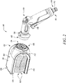
FIG. 2 illustrates a perspective view of the blind cleaning device disassembled from a fluid supply device, in accordance with an aspect of the present disclosure; -
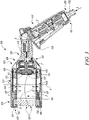
FIG. 3 illustrates a cross-sectional view of the blind cleaning device about a vertical plane, in accordance with an aspect of the present disclosure; -
FIG. 4 illustrates a perspective view of a body of the blind cleaning device and the fluid supply device in a second position, in accordance with an aspect of the present disclosure; -
FIG. 5 illustrates an exploded view of a body and a pair of bristle plates of the blind cleaning device, in accordance with an aspect of the present disclosure; -
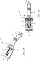
FIG. 6A illustrates a top view of the blind cleaning device, in accordance with an aspect of the present disclosure; and -
FIG. 6B illustrates a cross-sectional view of the blind cleaning device about a horizontal plane, in accordance with an aspect of the present disclosure. - The present disclosure will be described more fully hereinafter with reference to the accompanying drawings, in which example embodiments of the disclosure incorporating one or more aspects of the present disclosure are shown. This disclosure may, however, be embodied in many different forms and should not be construed as limited to the embodiments set forth herein; rather, these embodiments are provided so that this disclosure will be thorough and complete, and will fully convey the scope of the disclosure to those skilled in the art. For example, one or more aspects of the present disclosure may be utilized in other embodiments and even other types of structures and/or methods. In the drawings, like numbers refer to like elements.
- Certain terminology is used herein for convenience only and is not to be taken as a limitation on the disclosure. For example, "upper", "lower", "front", "rear", "side", "longitudinal", "lateral", "transverse", "upwards", "downwards", "forward", "backward", "sideward", "left," "right," "horizontal," "vertical," "upward", "inner", "outer", "inward", "outward", "top", "bottom", "higher", "above", "below", "central", "middle", "intermediate", "between", "end", "adjacent", "proximate", "near", "distal", "remote", "radial", "circumferential", or the like, merely describe the configuration shown in the Figures. Indeed, the components may be oriented in any direction and the terminology, therefore, should be understood as encompassing such variations unless specified otherwise.
-
FIG. 1 is a perspective view of ablind cleaning device 100. Theblind cleaning device 100 may be used for different cleaning applications, such as to clean a number of lamellae (not shown) of a window blind (not shown). The present disclosure illustrates a cleaning device as theblind cleaning device 100, however actual implementation of the present disclosure may be applied with any cleaning device making use of one or more brushes, bristles and the like. Theblind cleaning device 100 includes abody 102 defining abracket 104. Thebody 102 may be manufactured from a plastic, a metal, and the like. Thebody 102 may be embodied as a single piece unit or thebody 102 may include multiple separate parts that are joined together to form thebody 102. Thebody 102 may be coupled with different types of cleaning attachments, such as, brushes, showers, nozzle, and the like. Thebody 102 is coupled with afluid connection 103 which provides a fluid towards theblind cleaning device 100. The fluid connection may include a tap, pump, and the like. Further, the fluid may include water or any other cleaning fluid. - Referring to
FIG. 2 , thebracket 104 defines afirst end 106 and asecond end 108. Further, thebracket 104 of thebody 102 includes a generally U-shaped structure herein. It should be noted that thebracket 104 may include any other shape and size, without limiting the scope of the present disclosure. Thebracket 104 includes afirst surface 110. Thebracket 104 also includes a second surface 112 (shown inFIG. 5 ). Thebracket 104 also includes a number of projections 114 (shown inFIG. 5 ) on thesecond surface 112. In the illustrated example, thebracket 104 includes fourprojections 114. Thebody 102 includes aninlet portion 118. Theinlet portion 118 includes a threaded profile. Further, theinlet portion 118 defines a through-hole 144. -
FIG. 3 shows theblind cleaning device 100, in accordance with an embodiment of the present disclosure. In this embodiment, thebody 102 includes adistributor 127. Thedistributor 127 defines a T-shaped structure, although other shapes, types, dimensions, structure have been contemplated and are well within the scope. Thedistributor 127 includes aninlet channel 129 and twooutlet channels 131. Theoutlet channels 131 are substantially perpendicular to theinlet channel 129. Theinlet channel 129 is fluidly coupled to theinlet portion 118 of thebody 102 for a fluid flow "F" (or simply the fluid), such as water for cleaning, therethrough. Further, theoutlet channels 131, receive the fluid flow "F" from theinlet channel 129 to supply the fluid flow "F" to each bristleplate inlet opening 135 and a number ofoutlet openings 137. The fluid flow "F" from theoutlet channels 131 of thedistributor 127 enters thebristle plates inlet opening 135. Further, the fluid flow "F" is then discharged through theoutlet openings 137, such as for applications involving cleaning of the lamella of the window blind and the like. - The present disclosure refers to the "fluid" or the "fluid flow" which have been used interchangeably for ease of explanation and understanding. The fluid flow "F" through the
blind cleaning device 100 is illustrated inFIG. 3 for detail flow from ahose connector 130 to afluid supply device 124, and then to thedistributor 127 of thebody 102. This fluid flow "F" then splits in thedistributor 127 to move towards each bristleplate FIG. 3 . - Further, the
body 102 also includes an adjustable limitation stop 122 (shown inFIG. 3 ) for different lamella width. Thelimitation stop 122 may be integrated and work with thedistributor 127 to allow splitting of the fluid i.e., water from theinlet channel 129 to theoutlet channels 131. In some embodiments, theblind cleaning device 100 may not include anylimitation stop 122 and make application of thedistributor 127. In some embodiments, a connecting portion 142 (shown inFIG. 4 ) includes theadjustable limitation stop 122. Thelimitation stop 122 includes a cylindrical body defining an inlet (not shown) and an outlet (not shown). The inlet is fluidly coupled to theinlet portion 118 of thebody 102 to supply fluid, such as water for cleaning, therethrough. Further, the fluid is discharged through the outlet of thelimitation stop 122. Thelimitation stop 122 may accommodate a jet that allows discharge of fluid therethrough. Further, the limitation stop 122 can be adjusted for different lamella width. In some examples, the limitation stop 122 can be adjusted to accommodate the lamella width that approximately lies in a range of about 40 Millimeters (mm) to about 100 mm. Furthermore, the jet may be flat or conical. Thelimitation stop 122 may be adjusted to obtain different types of fluid jet, such as flat fluid jet, conical fluid jet, and the like. Specifically, the limitation stop 122 can be rotated to adjust a pattern of the jet. Further, thebody 102 is removably coupled with thefluid supply device 124 for supply of the fluid. Theinlet portion 118 of thebody 102 allows removable coupling of thebody 102 with thefluid supply device 124 using a rotatable joint 126. - The
blind cleaning device 100 also includes thefluid supply device 124. Thefluid supply device 124 includes anactuator 128 to allow passage of the fluid towards thebody 102 of theblind cleaning device 100. When actuated, theactuator 128 allows passage of fluid therethrough. It should be noted that thefluid supply device 124 may include any arrangement for passage of the fluid towards thebody 102 of theblind cleaning device 100, such as a button, a knob, a handle, and the like. Thefluid supply device 124 includes afirst inlet 116 and afirst outlet 120. Further, thehose connector 130 is removably attached to thefluid supply device 124. Thehose connector 130 is removably attached to thefirst inlet 116 of thefluid supply device 124. Thehose connector 130 includes a threadedsection 132 to removably couple a hose pipe (not shown) with thehose connector 130. The hose pipe may supply the fluid from thefluid connection 103 towards theblind cleaning device 100. - Further, the
blind cleaning device 100 includes the rotatable joint 126 between thebody 102 and thefluid supply device 124. The rotatable joint 126 includes a cylindrical body, a joint inlet (not shown), and a joint outlet (not shown). The joint inlet is connected to thefluid supply device 124 and the joint outlet is removably coupled with theinlet portion 118 of thebody 102. The joint outlet may be partially received through the through-holes 144. Further, the joint outlet may include a threaded section (not shown) for removable coupling with theinlet portion 118 of thebody 102. The rotatable joint 126 allows coupling of thebody 102 of theblind cleaning device 100 with thefluid supply device 124 at various angles. The rotatable joint 126 between thebody 102 and thefluid supply device 124 provides improved ergonomics during cleaning, such as of a soil-deep window (not shown). - In a first position or a vertical position, as illustrated in
FIGS. 1 to 3 , the rotatable joint 126 allows vertical coupling of thefluid supply device 124 with thebody 102 of theblind cleaning device 100. The first position of thefluid supply device 124 may create less disturbance for the user during the cleaning operation. Referring toFIG. 4 , in a second position or a horizontal position, the rotatable joint 126 allows horizontal coupling of thefluid supply device 124 with thebody 102 of theblind cleaning device 100. In the second position of thefluid supply device 124, the user may feel less weight during a cleaning operation. Further, the first/vertical and the second/horizontal positions of the rotatable joint 126 may allow different positions, angles, ergonomic styles for cleaning by thebody 102 of theblind cleaning device 100. Further, the present disclosure illustrates and discusses the first/vertical and the second/horizontal positions, however actual implementation may have many and other positions in between the first/vertical and the second/horizontal positions of the rotatable joint 126. - Referring to
FIG. 5 , theblind cleaning device 100 also includes a pair of bristle plates 134,136 to couple with thebracket 104 of thebody 102. Specifically, theblind cleaning device 100 includes the first bristleplate 134 and the second bristleplate 136 facing the first bristleplate 134 and spaced apart from the first bristleplate 134. The pair ofbristle plates bristle plates bristle plate first plate surface 138 and asecond plate surface 140. Thefirst plate surface 138 of thebristle plate first plate surface 138 includes anumber receiving slots 146 to receive theprojections 114 of thebracket 104. Thesecond plate surface 140 of thebristle plates bristle plates bracket 104 using a snap-fit connection. It should be noted that the pair ofbristle plates bracket 104 may be connected by any other means, without limiting the scope of the present disclosure. - The pair of
bristle plates portion 142. In the illustrated example, the pair ofbristle plates portion 142 are embodied as an integral unit. Alternatively, the pair ofbristle plates portion 142 may be embodied as separate parts that are joined together. The pair ofbristle plates portion 142 form a generally U-shaped structure. - The pair of
bristle plates bristle plates - As shown in
FIG. 5 , theblind cleaning device 100 further includes a pair of bristle brushes 150 coupled with the pair of thebristle plates second plate surface 140 and extend therefrom. Each of the pair of bristle brushes 150 includes the plurality ofbristles 152. The pair ofbristles 152 of the pair of bristle brushes 150 overlap each other. Thebristles 152 may be tilted and arranged in ashape 154 to suit the shape of the lamellae of the window blind. This arrangement may allow uniform cleaning of the lamella surface. Thebristles 152 may include a first row of bristles that are disposed on an outer side of the bristle brushes 150 and a second row of bristles that are disposed on an inner side of the bristle brushes 150. The first row of bristles may include soft bristles and the second row of bristles may include hard bristles. The first row of bristles and the second row of bristles may be in contact with each other. - The pair of bristle brushes 150 are removably coupled with the pair of
bristle plates plate FIG. 3 ) to removably couple the pair of bristle brushes 150. Thebristle fixation element 155 can be removably coupled to the bristleplates bristle fixation element 155 may be made up of a soft plastic material. Thebristle fixation element 155 allows removable coupling of the pair of bristle brushes 150 with thebristle plates bristles 152 of each bristlebrush bristles 152 may include any other material, without limiting the scope of the present invention. - Referring to
FIGS. 6A and 6B , different views of theblind cleaning device 100 is illustrated. As shown, at least one of the pair ofbristle plates 134, 136 (seeFIGS. 6A and 6B , respectively) define one ormore openings 148 to allow discharge of the fluid therefrom. The one ormore openings 148 are specifically provided to allow discharge or drainage of any excess amount or flow of the fluid during application of theblind cleaning device 100. Such discharge or drainage of the fluid will take place, through the one ormore openings 148, substantially perpendicular to the first and second bristleplates blind cleaning device 100. In the illustrated example, each of the first and second bristleplates opening 148. Alternatively, any one of the first and second bristleplates opening 148. Theopenings 148 of each bristleplate openings 148 are centrally disposed within thebristle plates openings 148. The fluid jet directed through the distributor 127 (with or without the limitation stop 122) may split through thedistributor 127 to discharge the fluid from theopenings 148 provided on thebristle plates bristle plates FIG. 6B ) with the pair of thebristle plates cleaning room 156. Thecleaning room 156 defines an axis "A" (shown inFIG. 3 ) normal to each opening 148 of thebristle plates cleaning room 156 may allow removal or discharge of the fluid (say water) therethrough. Particularly, thecleaning room 156 may allow the fluid to discharge along the axis "A" therethrough, to check or avoid any undesired splashing or movement of the fluid substantially perpendicular to the axis "A". Moreover, the arrangement ofbristles 152 and thecleaning room 156 avoids splashing of fluid during cleaning process. Further, afront side 158 of the pair of bristle brushes 150 may be covered with a textile material, a rubber material, a plastic sheet, a foil sheet, and the like, for additional protection against the splashing of fluid. - The
cleaning room 156 of the present disclosure is defined between the pair of thebristle plates cleaning room 156, which allows to receive and hold the fluid during cleaning by theblind cleaning device 100. Further, thecleaning room 156 may allow discharge of the fluid through theopening 148, while avoiding any undesired spillage or discharge of the liquid through or around the pair of bristle brushes 150. - Further, the pair of
bristle plates bristle plates plates bristle plates bristles 152 of the pair of bristle brushes 150 wear out. More particularly, in an event of wear out of thebristles 152, thebristle plates bristles 152. This height adjustable nature of thebristle plates cleaning room 156. Such change in the dimensions of thecleaning room 156 may be suitable for different applications or operational requirements, such as to control a rate of the fluid leaving the cleaning room 156 (say along the axis "A"). In an alternate example, thebracket 104 of theblind cleaning device 100 may include a rectangular shape with rounded corners instead of the U-shaped structure. Further, in such an example, each bristleplate rectangular bracket 104 using a number of mechanical fasteners and the connectingportion 142 may be omitted. - The present disclosure provides the improved
blind cleaning device 100 to clean the lamellae of window blinds effectively and efficiently. Theblind cleaning device 100 allows cleaning of the window blinds with or without fluid. Further, theblind cleaning device 100 allows removable coupling of different attachments, such as brushes, showers, nozzle, and the like. Theblind cleaning device 100 includes fewer parts and can be easily assembled without requiring additional tools. Further, theblind cleaning device 100 is easy and convenient to use for users and does not cause user fatigue. - In the drawings and specification, there have been disclosed preferred embodiments and examples of the disclosure and, although specific terms are employed, they are used in a generic and descriptive sense only and not for the purpose of limitation of the scope of the disclosure being set forth in the following claims.
-
- 100
- Blind Cleaning Device
- 102
- Body
- 103
- Fluid Connection
- 104
- Bracket
- 106
- First End
- 108
- Second End
- 110
- First Surface
- 112
- Second Surface
- 114
- Projections
- 116
- First Inlet
- 118
- Inlet Portion
- 120
- Second Inlet
- 122
- Limitation Stop
- 124
- Fluid Supply Device
- 126
- Rotatable Joint
- 127
- Distributor
- 128
- Actuator
- 129
- Inlet Channel
- 130
- Hose Connector
- 131
- Outlet Channel
- 132
- Threaded Section
- 134
- First Bristle Plate
- 135
- Inlet Opening
- 136
- Second Bristle Plate
- 137
- Outlet Opening
- 138
- First Plate Surface
- 140
- Second Plate Surface
- 142
- Connecting Portion
- 144
- Through-Hole
- 146
- Receiving Slots
- 148
- Opening
- 150
- Pair of Bristle Brushes
- 152
- Bristles
- 154
- Shape
- 155
- Bristle Fixation Element
- 156
- Cleaning Room
- 158
- Front Side
- A
- Axis
- D
- Distance
- F
- Fluid Flow
Claims (9)
- A blind cleaning device (100) comprising:a body (102) defining a bracket (104);a pair of bristle plates (134, 136) adapted to couple with the bracket (104) of the body (102), wherein the body (102) is adapted to couple with a fluid connection (103) which provides a fluid; anda pair of bristle brushes (150) adapted to couple with the pair of the bristle plates (134, 136), wherein each of the pair of bristle brushes (150) includes a plurality of bristles (152);characterized in that:the pair of bristle brushes (150) are coupled with the pair of the bristle plates (134, 136) such that the pair of bristle brushes (150) contact each other to define a cleaning room (156) with the pair of the bristle plates (134, 136), wherein the fluid connection (103) supplies the fluid into the cleaning room (156).
- The blind cleaning device (100) of claim 1, wherein the body (102) is removably coupled with a fluid supply device (124) for supply of the fluid.
- The blind cleaning device (100) of claim 2, wherein the blind cleaning device includes a rotatable joint (126) between the body (102) and the fluid supply device (124).
- The blind cleaning device (100) of claim 2 or 3, wherein a hose connector (130) is removably attached to the fluid supply device (124).
- The blind cleaning device (100) of claim 1, wherein at least one of the pair of bristle plates (134, 136) define one or more openings (148) to allow discharge of the fluid therefrom.
- The blind cleaning device (100) of claim 1, wherein the pair of bristle plates (134, 136) are substantially parallel and include a spring-loaded mechanism.
- The blind cleaning device (100) of claim 1, wherein the pair of bristle plates (134, 136) is height adjustable to change a distance (D) between the pair of bristle plates (134, 136).
- The blind cleaning device (100) of claim 1, wherein the body (102) includes an adjustable limitation stop (122) for different lamella width.
- The blind cleaning device (100) of claim 1, wherein the pair of bristle brushes (150) are removably coupled with the pair of the bristle plates (134,136).
Priority Applications (5)
| Application Number | Priority Date | Filing Date | Title |
|---|---|---|---|
| PL21186663.7T PL4122364T3 (en) | 2021-07-20 | 2021-07-20 | Blind cleaning device |
| EP21186663.7A EP4122364B1 (en) | 2021-07-20 | 2021-07-20 | Blind cleaning device |
| CN202280051420.5A CN117693309B (en) | 2021-07-20 | 2022-05-27 | Shutter cleaning device |
| PCT/EP2022/064412 WO2023001433A1 (en) | 2021-07-20 | 2022-05-27 | Blind cleaning device |
| TW111127103A TW202319011A (en) | 2021-07-20 | 2022-07-20 | Blind cleaning device |
Applications Claiming Priority (1)
| Application Number | Priority Date | Filing Date | Title |
|---|---|---|---|
| EP21186663.7A EP4122364B1 (en) | 2021-07-20 | 2021-07-20 | Blind cleaning device |
Publications (2)
| Publication Number | Publication Date |
|---|---|
| EP4122364A1 true EP4122364A1 (en) | 2023-01-25 |
| EP4122364B1 EP4122364B1 (en) | 2023-06-21 |
Family
ID=76999703
Family Applications (1)
| Application Number | Title | Priority Date | Filing Date |
|---|---|---|---|
| EP21186663.7A Active EP4122364B1 (en) | 2021-07-20 | 2021-07-20 | Blind cleaning device |
Country Status (5)
| Country | Link |
|---|---|
| EP (1) | EP4122364B1 (en) |
| CN (1) | CN117693309B (en) |
| PL (1) | PL4122364T3 (en) |
| TW (1) | TW202319011A (en) |
| WO (1) | WO2023001433A1 (en) |
Citations (6)
| Publication number | Priority date | Publication date | Assignee | Title |
|---|---|---|---|---|
| US2487444A (en) * | 1945-10-25 | 1949-11-08 | Julian M Ines | Suction brush for venetian blinds |
| US2608710A (en) * | 1950-06-06 | 1952-09-02 | Joseph P Zaidan | Suction brush for cleaning venetian blinds |
| US2788537A (en) * | 1953-12-18 | 1957-04-16 | Greenberg Seymour | Fluid holding venetian blind cleaner |
| US5400468A (en) * | 1990-08-10 | 1995-03-28 | De Petra; Andy | Slat cleaning apparatus |
| EP2147625A1 (en) * | 2008-07-21 | 2010-01-27 | Anton Jäger | Cleaning device |
| US20170127891A1 (en) * | 2014-06-25 | 2017-05-11 | Tzvi Deri | Device for cleaning a slat of a shutter having a specific lateral profile |
Family Cites Families (2)
| Publication number | Priority date | Publication date | Assignee | Title |
|---|---|---|---|---|
| CA394502A (en) * | 1941-02-11 | E. Mcphee Margaret | Venetian blind cleaning implement | |
| CN109330467A (en) * | 2018-10-26 | 2019-02-15 | 江门市品诚化工科技有限公司 | A kind of electrodynamic type shutter cleaning brush |
-
2021
- 2021-07-20 EP EP21186663.7A patent/EP4122364B1/en active Active
- 2021-07-20 PL PL21186663.7T patent/PL4122364T3/en unknown
-
2022
- 2022-05-27 WO PCT/EP2022/064412 patent/WO2023001433A1/en not_active Ceased
- 2022-05-27 CN CN202280051420.5A patent/CN117693309B/en active Active
- 2022-07-20 TW TW111127103A patent/TW202319011A/en unknown
Patent Citations (6)
| Publication number | Priority date | Publication date | Assignee | Title |
|---|---|---|---|---|
| US2487444A (en) * | 1945-10-25 | 1949-11-08 | Julian M Ines | Suction brush for venetian blinds |
| US2608710A (en) * | 1950-06-06 | 1952-09-02 | Joseph P Zaidan | Suction brush for cleaning venetian blinds |
| US2788537A (en) * | 1953-12-18 | 1957-04-16 | Greenberg Seymour | Fluid holding venetian blind cleaner |
| US5400468A (en) * | 1990-08-10 | 1995-03-28 | De Petra; Andy | Slat cleaning apparatus |
| EP2147625A1 (en) * | 2008-07-21 | 2010-01-27 | Anton Jäger | Cleaning device |
| US20170127891A1 (en) * | 2014-06-25 | 2017-05-11 | Tzvi Deri | Device for cleaning a slat of a shutter having a specific lateral profile |
Also Published As
| Publication number | Publication date |
|---|---|
| CN117693309A (en) | 2024-03-12 |
| CN117693309B (en) | 2024-08-09 |
| PL4122364T3 (en) | 2023-12-11 |
| EP4122364B1 (en) | 2023-06-21 |
| WO2023001433A1 (en) | 2023-01-26 |
| TW202319011A (en) | 2023-05-16 |
Similar Documents
| Publication | Publication Date | Title |
|---|---|---|
| CN109199267B (en) | Water washing cleaning device | |
| US6560818B1 (en) | Carpet cleaning wand boot | |
| US20200008640A1 (en) | Systems and methods for providing a wand for a floor cleaning apparatus | |
| CN104452900A (en) | Sanitary water outlet | |
| WO2007133649A2 (en) | Ergonomic window cleaning apparatus | |
| US10285550B2 (en) | Suction nozzle with at least two intermediate walls | |
| US7287926B2 (en) | Fluid squeegee | |
| EP4122364B1 (en) | Blind cleaning device | |
| WO2008123856A1 (en) | Shower enclosure and bathtub cleaning system | |
| US7194783B1 (en) | Window blind cleaning apparatus | |
| EP1508292B1 (en) | Nozzle assembly for vacuum cleaner for both wet and dry cleaning | |
| EP4373372B1 (en) | Blind cleaner device | |
| EP3081333B1 (en) | A sanding tool | |
| EP3135176B1 (en) | Squeegee with seal flap | |
| CN121154047A (en) | Gland assembly, cleaning head assembly and floor washing machine | |
| CN109114671A (en) | Strainer cleans component, air conditioner indoor unit and air conditioner | |
| TW201914410A (en) | Visible, removable filter for water tools | |
| EP4026423B1 (en) | Watering device | |
| US6883988B1 (en) | Vertical blind cleaning tool | |
| EP3592915B1 (en) | Gutter cleaner | |
| CN113071219B (en) | Nozzle structure of ink-jet printer | |
| CN116273525B (en) | Shower head for scrubbing and washing | |
| CN223706373U (en) | An outdoor brick and stone grout cleaning tool | |
| CN217244072U (en) | Cleaning machine system | |
| EP0286692B1 (en) | Apparatus for cleaning plane surfaces |
Legal Events
| Date | Code | Title | Description |
|---|---|---|---|
| PUAI | Public reference made under article 153(3) epc to a published international application that has entered the european phase |
Free format text: ORIGINAL CODE: 0009012 |
|
| STAA | Information on the status of an ep patent application or granted ep patent |
Free format text: STATUS: REQUEST FOR EXAMINATION WAS MADE |
|
| 17P | Request for examination filed |
Effective date: 20221103 |
|
| AK | Designated contracting states |
Kind code of ref document: A1 Designated state(s): AL AT BE BG CH CY CZ DE DK EE ES FI FR GB GR HR HU IE IS IT LI LT LU LV MC MK MT NL NO PL PT RO RS SE SI SK SM TR |
|
| GRAP | Despatch of communication of intention to grant a patent |
Free format text: ORIGINAL CODE: EPIDOSNIGR1 |
|
| STAA | Information on the status of an ep patent application or granted ep patent |
Free format text: STATUS: GRANT OF PATENT IS INTENDED |
|
| INTG | Intention to grant announced |
Effective date: 20230223 |
|
| GRAS | Grant fee paid |
Free format text: ORIGINAL CODE: EPIDOSNIGR3 |
|
| GRAA | (expected) grant |
Free format text: ORIGINAL CODE: 0009210 |
|
| STAA | Information on the status of an ep patent application or granted ep patent |
Free format text: STATUS: THE PATENT HAS BEEN GRANTED |
|
| AK | Designated contracting states |
Kind code of ref document: B1 Designated state(s): AL AT BE BG CH CY CZ DE DK EE ES FI FR GB GR HR HU IE IS IT LI LT LU LV MC MK MT NL NO PL PT RO RS SE SI SK SM TR |
|
| REG | Reference to a national code |
Ref country code: CH Ref legal event code: EP |
|
| REG | Reference to a national code |
Ref country code: DE Ref legal event code: R096 Ref document number: 602021003012 Country of ref document: DE |
|
| REG | Reference to a national code |
Ref country code: AT Ref legal event code: REF Ref document number: 1580282 Country of ref document: AT Kind code of ref document: T Effective date: 20230715 |
|
| REG | Reference to a national code |
Ref country code: IE Ref legal event code: FG4D |
|
| REG | Reference to a national code |
Ref country code: LT Ref legal event code: MG9D |
|
| REG | Reference to a national code |
Ref country code: NL Ref legal event code: MP Effective date: 20230621 |
|
| PG25 | Lapsed in a contracting state [announced via postgrant information from national office to epo] |
Ref country code: SE Free format text: LAPSE BECAUSE OF FAILURE TO SUBMIT A TRANSLATION OF THE DESCRIPTION OR TO PAY THE FEE WITHIN THE PRESCRIBED TIME-LIMIT Effective date: 20230621 Ref country code: NO Free format text: LAPSE BECAUSE OF FAILURE TO SUBMIT A TRANSLATION OF THE DESCRIPTION OR TO PAY THE FEE WITHIN THE PRESCRIBED TIME-LIMIT Effective date: 20230921 |
|
| REG | Reference to a national code |
Ref country code: AT Ref legal event code: MK05 Ref document number: 1580282 Country of ref document: AT Kind code of ref document: T Effective date: 20230621 |
|
| PG25 | Lapsed in a contracting state [announced via postgrant information from national office to epo] |
Ref country code: RS Free format text: LAPSE BECAUSE OF FAILURE TO SUBMIT A TRANSLATION OF THE DESCRIPTION OR TO PAY THE FEE WITHIN THE PRESCRIBED TIME-LIMIT Effective date: 20230621 Ref country code: NL Free format text: LAPSE BECAUSE OF FAILURE TO SUBMIT A TRANSLATION OF THE DESCRIPTION OR TO PAY THE FEE WITHIN THE PRESCRIBED TIME-LIMIT Effective date: 20230621 Ref country code: LV Free format text: LAPSE BECAUSE OF FAILURE TO SUBMIT A TRANSLATION OF THE DESCRIPTION OR TO PAY THE FEE WITHIN THE PRESCRIBED TIME-LIMIT Effective date: 20230621 Ref country code: LT Free format text: LAPSE BECAUSE OF FAILURE TO SUBMIT A TRANSLATION OF THE DESCRIPTION OR TO PAY THE FEE WITHIN THE PRESCRIBED TIME-LIMIT Effective date: 20230621 Ref country code: HR Free format text: LAPSE BECAUSE OF FAILURE TO SUBMIT A TRANSLATION OF THE DESCRIPTION OR TO PAY THE FEE WITHIN THE PRESCRIBED TIME-LIMIT Effective date: 20230621 Ref country code: GR Free format text: LAPSE BECAUSE OF FAILURE TO SUBMIT A TRANSLATION OF THE DESCRIPTION OR TO PAY THE FEE WITHIN THE PRESCRIBED TIME-LIMIT Effective date: 20230922 |
|
| PG25 | Lapsed in a contracting state [announced via postgrant information from national office to epo] |
Ref country code: FI Free format text: LAPSE BECAUSE OF FAILURE TO SUBMIT A TRANSLATION OF THE DESCRIPTION OR TO PAY THE FEE WITHIN THE PRESCRIBED TIME-LIMIT Effective date: 20230621 |
|
| PG25 | Lapsed in a contracting state [announced via postgrant information from national office to epo] |
Ref country code: SK Free format text: LAPSE BECAUSE OF FAILURE TO SUBMIT A TRANSLATION OF THE DESCRIPTION OR TO PAY THE FEE WITHIN THE PRESCRIBED TIME-LIMIT Effective date: 20230621 |
|
| PG25 | Lapsed in a contracting state [announced via postgrant information from national office to epo] |
Ref country code: ES Free format text: LAPSE BECAUSE OF FAILURE TO SUBMIT A TRANSLATION OF THE DESCRIPTION OR TO PAY THE FEE WITHIN THE PRESCRIBED TIME-LIMIT Effective date: 20230621 |
|
| PG25 | Lapsed in a contracting state [announced via postgrant information from national office to epo] |
Ref country code: IS Free format text: LAPSE BECAUSE OF FAILURE TO SUBMIT A TRANSLATION OF THE DESCRIPTION OR TO PAY THE FEE WITHIN THE PRESCRIBED TIME-LIMIT Effective date: 20231021 |
|
| PG25 | Lapsed in a contracting state [announced via postgrant information from national office to epo] |
Ref country code: SM Free format text: LAPSE BECAUSE OF FAILURE TO SUBMIT A TRANSLATION OF THE DESCRIPTION OR TO PAY THE FEE WITHIN THE PRESCRIBED TIME-LIMIT Effective date: 20230621 Ref country code: SK Free format text: LAPSE BECAUSE OF FAILURE TO SUBMIT A TRANSLATION OF THE DESCRIPTION OR TO PAY THE FEE WITHIN THE PRESCRIBED TIME-LIMIT Effective date: 20230621 Ref country code: RO Free format text: LAPSE BECAUSE OF FAILURE TO SUBMIT A TRANSLATION OF THE DESCRIPTION OR TO PAY THE FEE WITHIN THE PRESCRIBED TIME-LIMIT Effective date: 20230621 Ref country code: PT Free format text: LAPSE BECAUSE OF FAILURE TO SUBMIT A TRANSLATION OF THE DESCRIPTION OR TO PAY THE FEE WITHIN THE PRESCRIBED TIME-LIMIT Effective date: 20231023 Ref country code: IS Free format text: LAPSE BECAUSE OF FAILURE TO SUBMIT A TRANSLATION OF THE DESCRIPTION OR TO PAY THE FEE WITHIN THE PRESCRIBED TIME-LIMIT Effective date: 20231021 Ref country code: ES Free format text: LAPSE BECAUSE OF FAILURE TO SUBMIT A TRANSLATION OF THE DESCRIPTION OR TO PAY THE FEE WITHIN THE PRESCRIBED TIME-LIMIT Effective date: 20230621 Ref country code: EE Free format text: LAPSE BECAUSE OF FAILURE TO SUBMIT A TRANSLATION OF THE DESCRIPTION OR TO PAY THE FEE WITHIN THE PRESCRIBED TIME-LIMIT Effective date: 20230621 Ref country code: CZ Free format text: LAPSE BECAUSE OF FAILURE TO SUBMIT A TRANSLATION OF THE DESCRIPTION OR TO PAY THE FEE WITHIN THE PRESCRIBED TIME-LIMIT Effective date: 20230621 Ref country code: AT Free format text: LAPSE BECAUSE OF FAILURE TO SUBMIT A TRANSLATION OF THE DESCRIPTION OR TO PAY THE FEE WITHIN THE PRESCRIBED TIME-LIMIT Effective date: 20230621 |
|
| PG25 | Lapsed in a contracting state [announced via postgrant information from national office to epo] |
Ref country code: MC Free format text: LAPSE BECAUSE OF FAILURE TO SUBMIT A TRANSLATION OF THE DESCRIPTION OR TO PAY THE FEE WITHIN THE PRESCRIBED TIME-LIMIT Effective date: 20230621 |
|
| REG | Reference to a national code |
Ref country code: BE Ref legal event code: MM Effective date: 20230731 |
|
| PG25 | Lapsed in a contracting state [announced via postgrant information from national office to epo] |
Ref country code: LU Free format text: LAPSE BECAUSE OF NON-PAYMENT OF DUE FEES Effective date: 20230720 |
|
| REG | Reference to a national code |
Ref country code: DE Ref legal event code: R097 Ref document number: 602021003012 Country of ref document: DE |
|
| PG25 | Lapsed in a contracting state [announced via postgrant information from national office to epo] |
Ref country code: MC Free format text: LAPSE BECAUSE OF FAILURE TO SUBMIT A TRANSLATION OF THE DESCRIPTION OR TO PAY THE FEE WITHIN THE PRESCRIBED TIME-LIMIT Effective date: 20230621 Ref country code: LU Free format text: LAPSE BECAUSE OF NON-PAYMENT OF DUE FEES Effective date: 20230720 |
|
| REG | Reference to a national code |
Ref country code: IE Ref legal event code: MM4A |
|
| PLBE | No opposition filed within time limit |
Free format text: ORIGINAL CODE: 0009261 |
|
| STAA | Information on the status of an ep patent application or granted ep patent |
Free format text: STATUS: NO OPPOSITION FILED WITHIN TIME LIMIT |
|
| PG25 | Lapsed in a contracting state [announced via postgrant information from national office to epo] |
Ref country code: DK Free format text: LAPSE BECAUSE OF FAILURE TO SUBMIT A TRANSLATION OF THE DESCRIPTION OR TO PAY THE FEE WITHIN THE PRESCRIBED TIME-LIMIT Effective date: 20230621 |
|
| PG25 | Lapsed in a contracting state [announced via postgrant information from national office to epo] |
Ref country code: SI Free format text: LAPSE BECAUSE OF FAILURE TO SUBMIT A TRANSLATION OF THE DESCRIPTION OR TO PAY THE FEE WITHIN THE PRESCRIBED TIME-LIMIT Effective date: 20230621 |
|
| 26N | No opposition filed |
Effective date: 20240322 |
|
| P01 | Opt-out of the competence of the unified patent court (upc) registered |
Effective date: 20240419 |
|
| PG25 | Lapsed in a contracting state [announced via postgrant information from national office to epo] |
Ref country code: SI Free format text: LAPSE BECAUSE OF FAILURE TO SUBMIT A TRANSLATION OF THE DESCRIPTION OR TO PAY THE FEE WITHIN THE PRESCRIBED TIME-LIMIT Effective date: 20230621 Ref country code: IT Free format text: LAPSE BECAUSE OF FAILURE TO SUBMIT A TRANSLATION OF THE DESCRIPTION OR TO PAY THE FEE WITHIN THE PRESCRIBED TIME-LIMIT Effective date: 20230621 Ref country code: BE Free format text: LAPSE BECAUSE OF NON-PAYMENT OF DUE FEES Effective date: 20230731 |
|
| PG25 | Lapsed in a contracting state [announced via postgrant information from national office to epo] |
Ref country code: IE Free format text: LAPSE BECAUSE OF NON-PAYMENT OF DUE FEES Effective date: 20230720 |
|
| PG25 | Lapsed in a contracting state [announced via postgrant information from national office to epo] |
Ref country code: IE Free format text: LAPSE BECAUSE OF NON-PAYMENT OF DUE FEES Effective date: 20230720 Ref country code: FR Free format text: LAPSE BECAUSE OF NON-PAYMENT OF DUE FEES Effective date: 20230821 |
|
| PG25 | Lapsed in a contracting state [announced via postgrant information from national office to epo] |
Ref country code: BG Free format text: LAPSE BECAUSE OF FAILURE TO SUBMIT A TRANSLATION OF THE DESCRIPTION OR TO PAY THE FEE WITHIN THE PRESCRIBED TIME-LIMIT Effective date: 20230621 |
|
| PG25 | Lapsed in a contracting state [announced via postgrant information from national office to epo] |
Ref country code: BG Free format text: LAPSE BECAUSE OF FAILURE TO SUBMIT A TRANSLATION OF THE DESCRIPTION OR TO PAY THE FEE WITHIN THE PRESCRIBED TIME-LIMIT Effective date: 20230621 |
|
| REG | Reference to a national code |
Ref country code: CH Ref legal event code: PL |
|
| PG25 | Lapsed in a contracting state [announced via postgrant information from national office to epo] |
Ref country code: CH Free format text: LAPSE BECAUSE OF NON-PAYMENT OF DUE FEES Effective date: 20240731 |
|
| PGFP | Annual fee paid to national office [announced via postgrant information from national office to epo] |
Ref country code: PL Payment date: 20250603 Year of fee payment: 5 |
|
| PG25 | Lapsed in a contracting state [announced via postgrant information from national office to epo] |
Ref country code: CY Free format text: LAPSE BECAUSE OF FAILURE TO SUBMIT A TRANSLATION OF THE DESCRIPTION OR TO PAY THE FEE WITHIN THE PRESCRIBED TIME-LIMIT; INVALID AB INITIO Effective date: 20210720 |
|
| PG25 | Lapsed in a contracting state [announced via postgrant information from national office to epo] |
Ref country code: HU Free format text: LAPSE BECAUSE OF FAILURE TO SUBMIT A TRANSLATION OF THE DESCRIPTION OR TO PAY THE FEE WITHIN THE PRESCRIBED TIME-LIMIT; INVALID AB INITIO Effective date: 20210720 |
|
| PGFP | Annual fee paid to national office [announced via postgrant information from national office to epo] |
Ref country code: DE Payment date: 20250603 Year of fee payment: 5 |
|
| PG25 | Lapsed in a contracting state [announced via postgrant information from national office to epo] |
Ref country code: TR Free format text: LAPSE BECAUSE OF FAILURE TO SUBMIT A TRANSLATION OF THE DESCRIPTION OR TO PAY THE FEE WITHIN THE PRESCRIBED TIME-LIMIT Effective date: 20230621 |
|
| GBPC | Gb: european patent ceased through non-payment of renewal fee |
Effective date: 20250720 |
|
| PG25 | Lapsed in a contracting state [announced via postgrant information from national office to epo] |
Ref country code: GB Free format text: LAPSE BECAUSE OF NON-PAYMENT OF DUE FEES Effective date: 20250720 |