EP4121785B1 - Electric meter installation issue detection based on orientation change - Google Patents
Electric meter installation issue detection based on orientation change Download PDFInfo
- Publication number
- EP4121785B1 EP4121785B1 EP21714558.0A EP21714558A EP4121785B1 EP 4121785 B1 EP4121785 B1 EP 4121785B1 EP 21714558 A EP21714558 A EP 21714558A EP 4121785 B1 EP4121785 B1 EP 4121785B1
- Authority
- EP
- European Patent Office
- Prior art keywords
- electric meter
- subsequent
- acceleration measurements
- initial
- accelerometer
- Prior art date
- Legal status (The legal status is an assumption and is not a legal conclusion. Google has not performed a legal analysis and makes no representation as to the accuracy of the status listed.)
- Active
Links
Images




Classifications
-
- G—PHYSICS
- G01—MEASURING; TESTING
- G01R—MEASURING ELECTRIC VARIABLES; MEASURING MAGNETIC VARIABLES
- G01R22/00—Arrangements for measuring time integral of electric power or current, e.g. electricity meters
- G01R22/06—Arrangements for measuring time integral of electric power or current, e.g. electricity meters by electronic methods
- G01R22/061—Details of electronic electricity meters
- G01R22/068—Arrangements for indicating or signaling faults
-
- G—PHYSICS
- G01—MEASURING; TESTING
- G01P—MEASURING LINEAR OR ANGULAR SPEED, ACCELERATION, DECELERATION, OR SHOCK; INDICATING PRESENCE, ABSENCE, OR DIRECTION, OF MOVEMENT
- G01P15/00—Measuring acceleration; Measuring deceleration; Measuring shock, i.e. sudden change of acceleration
- G01P15/02—Measuring acceleration; Measuring deceleration; Measuring shock, i.e. sudden change of acceleration by making use of inertia forces using solid seismic masses
- G01P15/08—Measuring acceleration; Measuring deceleration; Measuring shock, i.e. sudden change of acceleration by making use of inertia forces using solid seismic masses with conversion into electric or magnetic values
- G01P15/0802—Details
-
- G—PHYSICS
- G01—MEASURING; TESTING
- G01R—MEASURING ELECTRIC VARIABLES; MEASURING MAGNETIC VARIABLES
- G01R11/00—Electromechanical arrangements for measuring time integral of electric power or current, e.g. of consumption
- G01R11/02—Constructional details
- G01R11/04—Housings; Supporting racks; Arrangements of terminals
-
- G—PHYSICS
- G01—MEASURING; TESTING
- G01R—MEASURING ELECTRIC VARIABLES; MEASURING MAGNETIC VARIABLES
- G01R11/00—Electromechanical arrangements for measuring time integral of electric power or current, e.g. of consumption
- G01R11/02—Constructional details
- G01R11/25—Arrangements for indicating or signalling faults
-
- G—PHYSICS
- G06—COMPUTING OR CALCULATING; COUNTING
- G06Q—INFORMATION AND COMMUNICATION TECHNOLOGY [ICT] SPECIALLY ADAPTED FOR ADMINISTRATIVE, COMMERCIAL, FINANCIAL, MANAGERIAL OR SUPERVISORY PURPOSES; SYSTEMS OR METHODS SPECIALLY ADAPTED FOR ADMINISTRATIVE, COMMERCIAL, FINANCIAL, MANAGERIAL OR SUPERVISORY PURPOSES, NOT OTHERWISE PROVIDED FOR
- G06Q50/00—Information and communication technology [ICT] specially adapted for implementation of business processes of specific business sectors, e.g. utilities or tourism
- G06Q50/06—Energy or water supply
-
- G—PHYSICS
- G01—MEASURING; TESTING
- G01R—MEASURING ELECTRIC VARIABLES; MEASURING MAGNETIC VARIABLES
- G01R11/00—Electromechanical arrangements for measuring time integral of electric power or current, e.g. of consumption
- G01R11/02—Constructional details
- G01R11/24—Arrangements for avoiding or indicating fraudulent use
-
- G—PHYSICS
- G01—MEASURING; TESTING
- G01R—MEASURING ELECTRIC VARIABLES; MEASURING MAGNETIC VARIABLES
- G01R22/00—Arrangements for measuring time integral of electric power or current, e.g. electricity meters
- G01R22/06—Arrangements for measuring time integral of electric power or current, e.g. electricity meters by electronic methods
- G01R22/061—Details of electronic electricity meters
- G01R22/063—Details of electronic electricity meters related to remote communication
-
- G—PHYSICS
- G01—MEASURING; TESTING
- G01R—MEASURING ELECTRIC VARIABLES; MEASURING MAGNETIC VARIABLES
- G01R22/00—Arrangements for measuring time integral of electric power or current, e.g. electricity meters
- G01R22/06—Arrangements for measuring time integral of electric power or current, e.g. electricity meters by electronic methods
- G01R22/061—Details of electronic electricity meters
- G01R22/066—Arrangements for avoiding or indicating fraudulent use
Definitions
- An electric meter measures electrical power consumed by a customer of an electric utility provider.
- the electric meter is plugged into a meter socket that is mounted in an enclosure on a pole, a building, or other structure.
- the electrical connection between the electric meter and the socket is formed with a series of male connectors, sometimes referred to as "blades,” which are received by a corresponding series of female connectors, also referred to as jaws.
- blades a series of male connectors
- the electric meter is oriented such that a front face of the electric meter is parallel to the vertical mounting surface (e.g., the meter is plumb).
- CN 108072778 A discloses an electricity larceny prevention circuit for an intelligent electric energy meter based on an MEMS acceleration sensor, and the circuit is characterized in that a single-chipmicrocomputer is electrically connected with a MEMS acceleration sensor circuit, a storage module circuit, and a temperature measurement circuit.
- the circuit can achieve the monitoring of suspected behaviors no matter whether the intelligent electric energy meter carries out the supply of power or not, and changes the passive electricity larceny prevention into the active electricity larceny prevention.
- US 2012/060606 A1 discloses apparatus and methodologies for detecting inversion tamper, removal tamper, and taps using a three-axes accelerometer sensor in a utility meter environment.
- Inversion tamper is detected upon power up if the acceleration value along Y axis is greater than or equal to some small positive threshold.
- Removal tamper is detected if the average acceleration change of both Y and Z axes is greater than or equal to the removal threshold.
- a tap is detected if the average acceleration change along the X axis is greater than or equal to the tap threshold.
- the initial acceleration values are set upon power up.
- Removal tamper detection and tap detection are distinguished using a moving average filter. Tap detection uses timing constraints to avoid false tap detections.
- the devices are utility meters that have a positioning detector; a microprocessor connected to receive readings from the positioning detector; a memory storage device in communication with the microprocessor, and at least one power source to provide power to the microprocessor and the memory storage device. Combining positioning readings with theft detection algorithms allows increased accuracy in the automated detection of theft, even when grid power is not available to power the accelerometer or compass.
- CN 104269015 B relates to a device for detecting whether power measurement device is attacked or not comprising a main control unit and a detection unit.
- the main control unit includes a main control module and the detection unit includes a detection control module, a 35kV high-voltage discharge detection module, and vibration and physical displacement.
- the main control module, the 35kV high voltage discharge detection module, the vibration and physical displacement detection module, and a strong magnetic detection module are respectively electrically connected with the detection control module.
- CN 108107249 A describes an electricity larceny prevention method based on a multi-dimensional positioning technology of an electric energy meter.
- the method comprises adding a positioning chip to an electric energy meter control circuit, wherein the positioning chip automatically communicates with the Beidou or GPS in real time to obtain positioning information of the electric energy meter; an electric energy meter master control CPU reads the positioning information from the positioning chip through a serial communication data interface, and compares the positioning information with the positioning information acquired for the first time when the electric energy meter is installed to generate event information about the position change of the electric energy meter; a court acquiring terminal sends the event information to a main station, and the main station confirms an electricity larceny position and related information through multi-dimensional analysis.
- the method can also generate an accurate topological map of the location of all the electric energy meters in a province and a distribution network, monitors the changes of the position information of the electric energy meters in real time, ensures the real-time performance of the customer service panorama, can determine the position information of the fault point accurately and quickly when a fault occurs to a certain electric energy meter in the distribution network, and provides real-time information support for rapid repair.
- a remote unit includes an electronics assembly, a housing, and a fastening member.
- the electronics assembly includes a communications module and an image sensor, having a lens with a field of view, that captures images of a display of a meter.
- the housing includes a cover coupled to a base member.
- the base member couples to the meter and includes an aperture.
- the electronics assembly is retained between the base member and the cover, such that the lens aligns with the aperture.
- the fastening member receives a portion of the housing in a hollow section.
- a mechanism of the fastening member attaches to a portion of the meter, maintaining the display in the field of view.
- the communications module transmits image data, derived from the captured images, to a hub unit.
- the hub unit processes the image data, and forwards information extracted from the image data to a remote server.
- a further challenge for utilities is that many meter installations (meter bases and load side wiring) are the property of the energy consumer (e.g., home owner or landlord). Damage to meter installations can occur suddenly in the case of storm or vehicle damage or slowly in the case of earth settling or heaving over many years and may not be noticed or reported by the energy consumer. Improper orientation can be an indication of damage to the electric meter or the electric meter installation.
- a method as defined in claim 1. Further, when the difference exceeds the threshold value, a timestamped event may be recorded and an alarm flag may be set.
- determining the initial orientation of the electric meter may include executing a firmware procedure to initiate the initial accelerometer measurements on the electric meter during installation. In some cases, determining the initial orientation of the electric meter may include initiating the initial accelerometer measurements from the accelerometer by the electric meter when the electric meter first registers on a network and transitions to an operational mode at an installation site.
- Continuously monitoring the subsequent acceleration measurements from the accelerometer may include receiving acceleration measurements from the accelerometer at predetermined time intervals.
- determining a difference between the initial orientation and the subsequent orientation comprises determining a difference between the initial acceleration measurements and the subsequent acceleration measurements. In some cases, determining a difference between the initial orientation and the subsequent orientation may include determining an initial tilt angle of the electric meter based on the initial acceleration measurements, determining a subsequent tilt angle of the electric meter based on the subsequent acceleration measurements, and comparing the initial tilt angle to the subsequent tilt angle.
- the method may further include determining a tilt angle difference of the electric meter at the predetermined time intervals when the acceleration measurements from the accelerometer are received.
- the tilt angle of the electric meter may be an angle in a front-to-back direction with respect to a front face of the electric meter, an angle in a side-to-side direction with respect to a front face of the electric meter, or an angle in a rotation direction around a vertical axis of the electric meter.
- an electric meter as defined in claim 7. Further, when the difference exceeds the threshold value, a timestamped event may be recorded and an alarm flag may be set.
- the processor of the electric meter may be further configured to determine a difference between the initial orientation and the subsequent orientation by determining a difference between the initial acceleration measurements and the subsequent acceleration measurements. In some cases, the processor of the electric meter may be further configured to determine a difference between the initial orientation and the subsequent orientation by: determining an initial tilt angle of the electric meter based on the initial acceleration measurements, determining a subsequent tilt angle of the electric meter based on the subsequent acceleration measurements, and comparing the initial tilt angle to the subsequent tilt angle.
- the processor may be further configured to receive the subsequent acceleration measurements at predetermined time intervals, and may be further configured to determine a tilt angle difference at the predetermined time intervals when the acceleration measurements from the accelerometer are received.
- the tilt angle of the electric meter may be an angle in a front-to-back direction with respect to a front face of the electric meter, an angle in a side-to-side direction with respect to a front face of the electric meter, or an angle in a rotation direction around a vertical axisof the electric meter.
- a timestamped event may be recorded and an alarm flag may be set.
- the processor may be further configured to determine a difference between the initial orientation and the subsequent orientation by determining a difference between the initial acceleration measurements and the subsequent acceleration measurements. In some cases, the processor may be further configured to determine a difference between the initial orientation and the subsequent orientation by: determining an initial tilt angle of the electric meter based on the initial acceleration measurements, determining a subsequent tilt angle of the electric meter based on the subsequent acceleration measurements, and comparing the initial tilt angle to the subsequent tilt angle.
- the processor may be further configured to receive the subsequent acceleration measurements at predetermined time intervals, and may be further configured to determine a tilt angle difference at the predetermined time intervals when the acceleration measurements from the accelerometer are received.
- Embodiments according to the present disclosure can detect possible changes to orientations of electric meter installations. Changes such as tilting of an electric meter from an initial orientation when the electric meter was installed can create safety or power quality issues. For example, changes to the orientation of the electric meter installation could create strain on electrical conductors or connectors, or even expose the electrical conductors resulting in shock or fire hazards. Detection of changes in the orientation of the electric meter installation can prevent loss of life as well as damage to structures and electrical equipment.
- FIG. 1 is a block diagram illustrating electrical connections to an electric meter and meter socket.
- the meter and meter socket are located at the customer premises.
- the meter measures and controls the electricity delivered to the customer premises via the electric distribution system (i.e., the grid).
- the meter may be combined with a communications module to enable the meter to communicate with other meters and with the utility.
- power from the grid 110 i.e., the electric distribution system
- Electrical wiring L1 and L2 may provide power from two phases of the grid.
- the neutral wire N sometimes referred to as ground, is connected between the grid 110 and the electrical service 140, for example, at an electrical service panel at a residential or commercial customer premises. In some installations, the neutral wire N may not have a connection within the meter socket. In other installations, the neutral wire N may be connected within the meter socket.
- the electrical service 140 is also connected to the meter socket 120 via corresponding electrical wiring L1 and L2.
- the meter socket 120 includes electrical connectors to provide electrical connections to the meter 130 when the meter 130 is plugged into the meter socket 120.
- An electrical connection between the grid 110 and the electrical service 140 is formed through the meter 130 when the meter 130 is plugged into the meter socket 120.
- voltage and current provided by the grid 110 to the electrical service 140 is measured, or metered, by measuring devices 135, for example, voltage transformers and current transformers. Power delivered to the electrical service 140 may be calculated based on the voltage and current measurements.
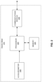
- FIG. 2 is a block diagram illustrating an example implementation of an electric meter according to aspects of the present disclosure.
- the electric meter 210 may include a processor 220, a memory 230, an accelerometer 250, and a communications module 240.
- the processor 220 may be a general purpose processor, a digital signal processor (DSP), an application specific integrated circuit (ASIC), a field programmable gate array (FPGA) or other programmable logic device.
- the processor 220 may be in electrical communication with the accelerometer 250, the memory 230, and the communications module 240, and may control overall operation of the electric meter 210.
- the processor 220 may receive data generated by various sensors of the electric meter 210 including, but not limited to, data generated by the accelerometer 250 and may perform operations on, or processing of, the data.
- the data generated by the accelerometer 250 may be timestamped by the accelerometer 250 or the processor 220.
- the accelerometer data may not include a timestamp.
- the memory 230 may be a storage device such as a solid state storage device or other storage device, and may be a combination of volatile and non-volatile storage or memory. In some implementations, portions of the memory may be included in the processor 220.
- the memory 230 may be configured to store instructions executable by the processor 220 as well as data generated by various sensors of the electric meter 210 including, but not limited to, data generated by the accelerometer 250.
- the accelerometer 250 may monitor vibrations experienced by the electric meter 210.
- the processor 220 may receive timestamped data from the accelerometer 250 or may receive and timestamp the accelerometer data.
- the processor 220 may cause the timestamped accelerometer data to be stored, for example in the memory 230 or other storage.
- the accelerometer data may be stored for a specified period of time.
- the communications module 240 may be a wired or wireless transceiver operable to communicate via various wired or wireless protocols as known in the field.
- the communications module 240 may enable the electric meter 210 to communicate with other meters and with the utility provider, for example, with a head-end system.
- the communications module may be, for example, a radio frequency (RF) transceiver configured to wirelessly communicate with a head-end system and other electric meters and devices in a communications network.
- RF radio frequency
- Many technologies are available for RF communications, for example, but not limited to, Cat-M, Cat-1, NB-IoT, ZigBee, Bluetooth, Wi-Fi, Wi-SUN, and cellular, as well as proprietary protocols, and the technologies may use many different frequencies.
- the head-end system may be, for example, a server situated in an office location of a utility provider.
- the head-end system may communicate with the electric meters to collect meter identification information such as serial numbers, advanced metering infrastructure (AMI) identifiers, other utility-specific identifiers, as well as data generated by the electric meters such as global positioning system (GPS) coordinates, voltage and current data, accelerometer data, and notifications.
- the communications module 240 may transmit data and alarm signals to the utility provider head-end system and receive any of updated program instructions, firmware updates, updates to other settings, or other communications.
- the accelerometer 250 may be a 2-axis accelerometer, a 3-axis accelerometer, or other accelerometer.
- the accelerometer 250 may be operable to detect static acceleration due to gravity. By measuring the amount of static acceleration due to gravity, the accelerometer 250 or the processor 220 can determine the angle the electric meter 210 is tilted at with respect to the earth.
- the accelerometer 250 may be operable to detect vibrations in a range of several hertz to several hundred hertz. Thus, the accelerometer 250 may detect vibrations due to insertions and removals of the electric meter.
- the electric meter When an electric meter is installed at a customer premises, for example, on a vertical mounting surface such as pole or on a side of a building, the electric meter is oriented such that a front face of the electric meter is substantially parallel to the vertical mounting surface (e.g., the meter is plumb). The electric meter is thus considered to be mounted in a vertical orientation. Measurements from an accelerometer, for example, the accelerometer 250, positioned in the electric meter can be used to determine the orientation of the electric meter with respect to gravity when the electric is installed.
- initial orientation measurements may be obtained from the accelerometer by causing the electric meter to execute a firmware procedure.
- the firmware procedure may be initiated by a technician and may cause the accelerometer to perform the static acceleration measurements, and the initial orientation determination may be performed by the accelerometer and/or the processor of the electric meter based on the accelerometer signals.
- the initial orientation measurements may be initiated by the electric meter when the electric meter registers with the utility provider network and transitions to an operational mode at the installation site.
- the accelerometer measurements obtained when the electric meter is installed may be stored, for example, in the memory 230 of the electric meter, as the baseline orientation.
- the processor of the electric meter may cause the baseline orientation to be communicated to the head-end system via the communications module.
- the baseline accelerometer measurements may be compared with subsequently obtained accelerometer measurements to determine whether the orientation of the electric meter has changed.
- the baseline accelerometer measurements may be compared directly with subsequently obtained accelerometer measurements.
- tilt angles of the electric meter determined based on the baseline accelerometer measurements and tilt angles of the electric meter determined based on the subsequently obtained accelerometer measurements may be compared.
- FIG. 3 is a diagram illustrating a change in electric meter orientation in a front-to-back direction.
- an electric meter 310 may be installed in a substantially vertical orientation. Measurements may be obtained from the accelerometer positioned in the electric meter to establish a baseline orientation of the electric meter in the front-to-back (e.g., pitch) direction with respect to a front face of the electric meter.
- the processor of the electric meter may receive the accelerometer measurements and determine the baseline orientation of the electric meter in the front-to-back direction.
- the accelerometer may determine the baseline orientation of the electric meter in the front-to-back direction from the obtained measurements and communicate the baseline orientation to the processor.
- the electric meter orientation in the front-to-back direction may be determined as a tilt angle ⁇ (e.g., a difference angle from a true vertical direction) of the electric meter.
- the baseline front-to-back orientation measurements may be stored, for example, in the memory of the electric meter.
- the processor may cause the communications module to communicate the baseline front-to-back orientation measurements to the head end system.
- the accelerometer may continuously measure the front-to-back orientation of the electric meter and communicate the measurements or the determined front-to-back orientation to the processor. In some example embodiments, the accelerometer may measure the front-to-back orientation of the electric meter at predetermined time intervals, for example, periods of seconds, minutes, hours, days, etc., and communicate measurements or the front-to-back orientation of the electric meter to the processor.
- Various external conditions can cause the orientation of the electric meter to tilt in a forward direction 330 or backward direction 340 with respect to a frame of reference of the electric meter 310.
- the change in orientation may be sudden, for example, as a result of a vehicle impact with a pole or wall on which the electric meter 310 is mounted.
- the change in orientation may occur over a period of time, for example, as the land around the electric meter 310 settles.
- the accelerometer positioned in the electric meter 310 can detect the changes in orientation by determining a change in magnitude of a gravity vector measured along the appropriate axes.
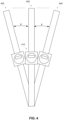
- FIG. 4 is a diagram illustrating a change in electric meter orientation in a side-to-side direction.
- an electric meter 410 may be installed in a substantially vertical orientation. Measurements may be obtained from the accelerometer positioned in the electric meter to establish a baseline orientation of the electric meter in the side-to-side (e.g., roll) direction with respect to a front face of the electric meter.
- the processor of the electric meter may receive the accelerometer measurements and determine the baseline orientation of the electric meter in the side-to-side direction.
- the accelerometer may determine the baseline orientation of the electric meter in the side-to-side direction from the obtained measurements and communicate the baseline orientation to the processor.
- the electric meter orientation in the side-to-side direction may be determined as a tilt angle ⁇ (e.g., a difference angle from a true vertical direction) of the electric meter.
- the baseline side-to-side orientation measurements may be stored, for example, in the memory of the electric meter.
- the processor may cause the communications module to communicate the baseline side-to-side orientation measurements to the head end system.
- the accelerometer may continuously measure the side-to-side orientation of the electric meter and communicate the measurements or the determined side-to-side orientation of the electric meter to the processor. In some example embodiments, the accelerometer may measure the side-to-side orientation of the electric meter at predetermined time intervals, for example, periods of seconds, minutes, hours, days, etc., and communicate measurements or the side-to-side orientation to the processor.
- Various external conditions can cause the orientation of the electric meter to tilt in a left side direction 430 or right side direction 440 with respect to a frame of reference of the electric meter 410.
- the change in orientation may be sudden, for example, as a result of a vehicle impact with a pole or wall on which the electric meter 410 is mounted.
- the change in orientation may occur over a period of time, for example, as the land around the electric meter 410 settles.
- the measurements from the accelerometer positioned in the electric meter 410 can detect the changes in orientation by determining a change in magnitude of a gravity vector measured along the appropriate axes.
- FIG. 5 is a diagram illustrating a change in electric meter orientation in a rotation direction around a vertical axis of the electric meter.
- an electric meter 510 may be installed in a substantially vertical orientation. Measurements may be obtained from the accelerometer positioned in the electric meter to establish a baseline orientation of the electric meter in the rotation (e.g., yaw) rotation direction around the vertical axis of the electric meter.
- the processor of the electric meter may receive the accelerometer measurements and determine the baseline orientation of the electric meter in the rotation direction.
- the accelerometer may determine the baseline orientation of the electric meter in the rotation direction from the obtained measurements and communicate the baseline orientation to the processor.
- the electric meter orientation in the rotation direction may be determined as a tilt angle ⁇ of the electric meter.
- the tilt angle ⁇ may be taken as an angle of zero degrees rotation around the vertical axis of the electric meter.
- the baseline rotation orientation measurements may be stored, for example, in the memory of the electric meter.
- the processor may cause the communications module to communicate the baseline rotation orientation measurements to the head end system.
- the accelerometer may continuously measure the rotation orientation of the electric meter and communicate the measurements or the determined rotation orientation of the electric meter to the processor. In some example embodiments, the accelerometer may measure the rotation orientation of the electric meter at predetermined time intervals, for example, periods of seconds, minutes, hours, days, etc., and communicate measurements or the rotation orientation to the processor.
- Various external conditions for example, high wind, structural deterioration, vehicle impact, land settling, etc., can cause the orientation of the electric meter to tilt in a left rotation direction 530 or right rotation direction 540 with respect to a vertical axis of the electric meter 510.
- the change in orientation may be sudden, for example, as a result of a vehicle impact with a pole or wall on which the electric meter 510 is mounted.
- the change in orientation may occur over a period of time, for example, as the land around the electric meter 510 settles.
- the measurements from the accelerometer positioned in the electric meter 510 can detect the changes in orientation by determining a change in magnitude of a gravity vector measured along the appropriate axes.
- the change in orientation of the electric meter detected by the accelerometer measurements may be compared to a threshold.
- the processor of the electric meter may receive the accelerometer signals and calculate a tilt angle ⁇ in a front-to-back direction, a tilt angle ⁇ in a side-to-side direction or a tilt angle ⁇ in the rotation direction, or tilt angles in all of the front-to-back, side-to-side, and rotation directions compared to the baseline orientation of the electric meter.
- the threshold value may be specified as a positive value and the absolute values of the tilt angles may be taken for the comparison.
- the threshold value may be specified as signed values (e.g., ⁇ 15 degrees) and the tilt angles compared according to their signed values.
- the processor may cause the communications module to generate a notification to the head-end system.
- the notification may include a timestamped event recorded in a location in the memory (e.g., the memory 230) or in a register in the processor (e.g., the processor 220) and an alarm flag may set in a location in the memory or in a register in the processor.
- a technician may be dispatched to investigate the cause of the notification.
- the accelerometer signals may indicate oscillations, for example, caused by a pole on which the electric meter is mounted swaying in high winds.
- the oscillations detected by the accelerometer may be an indication that the electrical wiring connected to the pole may be experiencing excessive strain that may ultimately result in downed wires or other failure conditions.
- the electric meter may apply a filter (not shown) to detect and filter out temporary oscillations due to typical wind conditions.
- FIGS. 3-5 illustrate an electric meter installed on a pole
- other installations for example on the wall of a building, may be used without departing from the scope of the present disclosure.
- FIG. 6 is a block diagram illustrating communications between electric meters and a head end system according to some aspects of the present disclosure.
- electric meters 610, 620, 630 may be in communication with a head-end system 640 via communication links 650 and may be in communication with each other via communication links 660.
- the head-end system 640 may include a server 645 configured to communicate with electric meters 610, 620, 630 over a network, for example in Advanced Metering Infrastructure (AMI) network.
- AMI Advanced Metering Infrastructure
- Each electric meter 610, 620, 630 may communicate meter information and data with other electric meters and with the server 645 in the head end system 640.
- AMI Advanced Metering Infrastructure
- an electric meter for example electric meter 620
- the electric meter 620 may be too remote from the head-end system 640 to communicate with it directly.
- the electric meter 620 may communicate with the head-end system 640 via another electric meter, for example electric meter 610.
- communications between electric meters and the head-end system may be communicated through additional networks (not shown). Additionally or alternatively, the electric meters may communicate with one or more edge processing device located topologically closer to the electric meters than to the head-end system.
- the edge processing device may have more processing capability than the electric meters and may provide some of the functionality typically provided by the head-end system.
- the electric meters 610, 620, 630 may communicate with each other via communication links 660 to exchange meter information and data. For example, if electric meter 610 experiences a loss of line voltage, electric meter 610 may communicate with electric meter 620 and electric meter 630 to determine if the failure is local to electric meter 610 or whether the failure is a more widespread fault caused by a common condition.
- a common condition may be, for example, downed power lines due to a storm. The common condition may then be reported to the head-end system by one or more of the electric meters. Additionally or alternatively, an edge processing device may receive data from the electric meters and determine whether the data indicates a common condition affecting the electric meters.
- FIG. 7 is a flowchart illustrating a method 700 for measuring tilt of an electric meter according to some aspects of the present disclosure.
- an electric meter may be installed at a customer premises.
- the electric meter may be installed on a pole or on the wall of a building or other structure.
- the electric meter may be installed in a substantially vertical orientation such that a front face of the electric meter is substantially parallel to the vertical mounting surface (e.g., the meter is plumb).
- the electric meter is thus considered to be mounted in a vertical orientation.
- a baseline orientation of the electric meter may be established.
- An accelerometer positioned in the electric meter may be operable to detect static acceleration of the electric meter due to gravity. By measuring the amount of static acceleration due to gravity, the angle that the electric meter is tilted at with respect to the earth can be determined when the electric meter is installed at the customer premises.
- the accelerometer measurements may be received by the processor of the electric meter, and the processor may perform calculations to determine a tilt angle.
- the accelerometer may perform the calculations to determine a tilt angle based on the measurements and communicate the tilt angle to the processor of the electric meter.
- the accelerometer measurements or the tilt angle or both obtained at installation of the electric meter may be stored in the memory of the electric meter as the baseline orientation.
- the processor of the electric meter may cause the baseline orientation to be communicated to the head-end system via the communications module.
- the baseline orientation may be established in the front-to-back (e.g., pitch) direction, the side-to-side (e.g., roll) direction, and the rotation (e.g., yaw) direction of the electric meter as illustrated in and explained with respect to FIGS. 3-5 .
- acceleration of the electric meter due to gravity may continue to be measured.
- the accelerometer positioned in the electric meter may continue to measure the acceleration due to gravity of the electric meter in both the front-to-back (e.g., pitch), side-to-side (e.g., roll), and rotation (e.g., yaw) directions.
- the accelerometer may continuously measure the acceleration due to gravity of the electric meter.
- the accelerometer may measure the acceleration due to gravity of the electric meter at predetermined time intervals, for example, periods of seconds, minutes, hours, days, etc. The accelerometer may communicate the measurements to the processor of the electric meter.
- a subsequent orientation of the electric meter may be determined.
- the subsequent orientation of the electric meter may be determined based on the subsequent acceleration measurements.
- the accelerometer measurements may be received by the processor of the electric meter, and the processor may perform calculations to determine a tilt angle of the electric meter.
- the accelerometer may perform the calculations to determine a tilt angle based on the measurements and communicate the tilt angle to the processor of the electric meter.
- a tilt angle may be determined in both the front-to-back direction, side-to-side direction, and rotation direction of the electric meter.
- a difference between the initial and subsequent orientations of the electric meter may be determined.
- the processor may compare the tilt angles based on the subsequent accelerometer measurements to the tilt angles of the baseline orientation (e.g., the front-to-back, side-to-side, and rotation tilt angles at the time of electric meter installation).
- the processor of the electric meter may compare the subsequent accelerometer measurements with the accelerometer measurements obtained at the time of electric meter installation without calculating tilt angles.
- the tilt angles or acceleration measurements may be compared to threshold values.
- the processor of the electric meter may determine whether the absolute value of the difference in the front-to-back tilt angle (e.g., the angle ⁇ in FIG. 3 ) or the difference in the side-to-side tilt angle (e.g., the angle ⁇ in FIG. 4 ) or the rotation tilt angle e.g., the angle ⁇ in FIG. 5 ) or all of the tilt angles exceeds the threshold value.
- the threshold value may be a difference in angle of, for example, 15 degrees or another angle from the baseline orientation.
- the threshold value for the front-to-back orientation, the side-to-side orientation, and the rotation orientation directions of the electric meter may be the same as or different.
- the threshold value may be specified as a positive value and the absolute values of the tilt angles may be taken for the comparison. In other implementations, the threshold value may be specified as signed values (e.g., ⁇ 15 degrees) and the tilt angles compared according to their signed values. In some embodiments, the processor may compare the subsequent accelerometer measurements with the initial accelerometer measurements obtained at the time of electric meter installation without calculating tilt angles. Threshold values may then be specified in terms of a difference in the accelerometer measurements rather than in terms of a tilt angle.
- a notification may be generated to the head-end system.
- the notification may be an alarm signal or other indication that the orientation of the electric meter has change beyond an allowable limit.
- the notification may include a timestamped event recorded in a memory location for example, in a location in the memory (e.g., the memory 230) or in a register in the processor (e.g., the processor 220) and an alarm flag set in a location in the memory or in a register in the processor.
- FIG. 7 provides a particular method for measuring tilt of an electric meter installation according to an embodiment of the present disclosure.
- Other sequences of steps may also be performed according to alternative embodiments.
- alternative embodiments may perform the steps outlined above in a different order.
- the individual steps illustrated in FIG. 7 may include multiple sub-steps that may be performed in various sequences as appropriate to the individual step.
- additional steps may be added or removed depending on the particular applications.
- One of ordinary skill in the art would recognize many variations, modifications, and alternatives.
- changes in electric meter orientation based on accelerometer measurements may be used to detect tampering with the meter.
- an electric meter may be powered down, carefully removed from its socket, and powered back up such that a typical accelerometer signal signature cannot be detected.
- the change in orientation of the electric meter detected in accordance with the present disclosure would be notified to the utility provider.
- a change in any tilt angle exceeding the threshold value accompanied by a loss of voltage may indicate that the electric meter has been removed.
- the stored energy in the electric meter can provide sufficient power to transmit the notification of meter removal to the head-end system.
Landscapes
- General Physics & Mathematics (AREA)
- Physics & Mathematics (AREA)
- Business, Economics & Management (AREA)
- Engineering & Computer Science (AREA)
- Health & Medical Sciences (AREA)
- Economics (AREA)
- Strategic Management (AREA)
- Theoretical Computer Science (AREA)
- Marketing (AREA)
- Primary Health Care (AREA)
- General Health & Medical Sciences (AREA)
- Tourism & Hospitality (AREA)
- Water Supply & Treatment (AREA)
- General Business, Economics & Management (AREA)
- Public Health (AREA)
- Human Resources & Organizations (AREA)
- Power Engineering (AREA)
- Arrangements For Transmission Of Measured Signals (AREA)
- Management, Administration, Business Operations System, And Electronic Commerce (AREA)
- Length Measuring Devices With Unspecified Measuring Means (AREA)
- Navigation (AREA)
- Geophysics And Detection Of Objects (AREA)
- Switches Operated By Changes In Physical Conditions (AREA)
Description
- An electric meter measures electrical power consumed by a customer of an electric utility provider. The electric meter is plugged into a meter socket that is mounted in an enclosure on a pole, a building, or other structure. The electrical connection between the electric meter and the socket is formed with a series of male connectors, sometimes referred to as "blades," which are received by a corresponding series of female connectors, also referred to as jaws. When an electric meter is installed at a customer premises, the electric meter is oriented such that a front face of the electric meter is parallel to the vertical mounting surface (e.g., the meter is plumb).
-
CN 108072778 A discloses an electricity larceny prevention circuit for an intelligent electric energy meter based on an MEMS acceleration sensor, and the circuit is characterized in that a single-chipmicrocomputer is electrically connected with a MEMS acceleration sensor circuit, a storage module circuit, and a temperature measurement circuit. The circuit can achieve the monitoring of suspected behaviors no matter whether the intelligent electric energy meter carries out the supply of power or not, and changes the passive electricity larceny prevention into the active electricity larceny prevention. -
US 2012/060606 A1 discloses apparatus and methodologies for detecting inversion tamper, removal tamper, and taps using a three-axes accelerometer sensor in a utility meter environment. Inversion tamper is detected upon power up if the acceleration value along Y axis is greater than or equal to some small positive threshold. Removal tamper is detected if the average acceleration change of both Y and Z axes is greater than or equal to the removal threshold. A tap is detected if the average acceleration change along the X axis is greater than or equal to the tap threshold. The initial acceleration values are set upon power up. Removal tamper detection and tap detection are distinguished using a moving average filter. Tap detection uses timing constraints to avoid false tap detections. - In
US 2016/351028 A1 devices to detect utility theft are provided, as well as methods of their use. The devices are utility meters that have a positioning detector; a microprocessor connected to receive readings from the positioning detector; a memory storage device in communication with the microprocessor, and at least one power source to provide power to the microprocessor and the memory storage device. Combining positioning readings with theft detection algorithms allows increased accuracy in the automated detection of theft, even when grid power is not available to power the accelerometer or compass. -
CN 104269015 B relates to a device for detecting whether power measurement device is attacked or not comprising a main control unit and a detection unit. The main control unit includes a main control module and the detection unit includes a detection control module, a 35kV high-voltage discharge detection module, and vibration and physical displacement. The main control module, the 35kV high voltage discharge detection module, the vibration and physical displacement detection module, and a strong magnetic detection module are respectively electrically connected with the detection control module. -
CN 108107249 A describes an electricity larceny prevention method based on a multi-dimensional positioning technology of an electric energy meter. The method comprises adding a positioning chip to an electric energy meter control circuit, wherein the positioning chip automatically communicates with the Beidou or GPS in real time to obtain positioning information of the electric energy meter; an electric energy meter master control CPU reads the positioning information from the positioning chip through a serial communication data interface, and compares the positioning information with the positioning information acquired for the first time when the electric energy meter is installed to generate event information about the position change of the electric energy meter; a court acquiring terminal sends the event information to a main station, and the main station confirms an electricity larceny position and related information through multi-dimensional analysis. The method can also generate an accurate topological map of the location of all the electric energy meters in a province and a distribution network, monitors the changes of the position information of the electric energy meters in real time, ensures the real-time performance of the customer service panorama, can determine the position information of the fault point accurately and quickly when a fault occurs to a certain electric energy meter in the distribution network, and provides real-time information support for rapid repair. -
US 2018/052008 A1 relates to a meter reading device and system. A remote unit includes an electronics assembly, a housing, and a fastening member. The electronics assembly includes a communications module and an image sensor, having a lens with a field of view, that captures images of a display of a meter. The housing includes a cover coupled to a base member. The base member couples to the meter and includes an aperture. The electronics assembly is retained between the base member and the cover, such that the lens aligns with the aperture. The fastening member receives a portion of the housing in a hollow section. A mechanism of the fastening member attaches to a portion of the meter, maintaining the display in the field of view. The communications module transmits image data, derived from the captured images, to a hub unit. The hub unit processes the image data, and forwards information extracted from the image data to a remote server. - One issue that utilities face is unreported damage to their assets, of which one such asset is the electric meter. A further challenge for utilities is that many meter installations (meter bases and load side wiring) are the property of the energy consumer (e.g., home owner or landlord). Damage to meter installations can occur suddenly in the case of storm or vehicle damage or slowly in the case of earth settling or heaving over many years and may not be noticed or reported by the energy consumer. Improper orientation can be an indication of damage to the electric meter or the electric meter installation.
- Systems and methods for detecting changes in the orientation of an electric meter are provided.
- According to various aspects of the present disclosure there is provided a method, as defined in claim 1. Further, when the difference exceeds the threshold value, a timestamped event may be recorded and an alarm flag may be set.
- In some cases, determining the initial orientation of the electric meter may include executing a firmware procedure to initiate the initial accelerometer measurements on the electric meter during installation. In some cases, determining the initial orientation of the electric meter may include initiating the initial accelerometer measurements from the accelerometer by the electric meter when the electric meter first registers on a network and transitions to an operational mode at an installation site.
- Continuously monitoring the subsequent acceleration measurements from the accelerometer may include receiving acceleration measurements from the accelerometer at predetermined time intervals.
- In some cases, determining a difference between the initial orientation and the subsequent orientation comprises determining a difference between the initial acceleration measurements and the subsequent acceleration measurements. In some cases, determining a difference between the initial orientation and the subsequent orientation may include determining an initial tilt angle of the electric meter based on the initial acceleration measurements, determining a subsequent tilt angle of the electric meter based on the subsequent acceleration measurements, and comparing the initial tilt angle to the subsequent tilt angle.
- The method may further include determining a tilt angle difference of the electric meter at the predetermined time intervals when the acceleration measurements from the accelerometer are received. The tilt angle of the electric meter may be an angle in a front-to-back direction with respect to a front face of the electric meter, an angle in a side-to-side direction with respect to a front face of the electric meter, or an angle in a rotation direction around a vertical axis of the electric meter.
- According to various aspects of the present disclosure there is provided an electric meter, as defined in claim 7. Further, when the difference exceeds the threshold value, a timestamped event may be recorded and an alarm flag may be set.
- In some cases, the processor of the electric meter may be further configured to determine a difference between the initial orientation and the subsequent orientation by determining a difference between the initial acceleration measurements and the subsequent acceleration measurements. In some cases, the processor of the electric meter may be further configured to determine a difference between the initial orientation and the subsequent orientation by: determining an initial tilt angle of the electric meter based on the initial acceleration measurements, determining a subsequent tilt angle of the electric meter based on the subsequent acceleration measurements, and comparing the initial tilt angle to the subsequent tilt angle.
- The processor may be further configured to receive the subsequent acceleration measurements at predetermined time intervals, and may be further configured to determine a tilt angle difference at the predetermined time intervals when the acceleration measurements from the accelerometer are received. The tilt angle of the electric meter may be an angle in a front-to-back direction with respect to a front face of the electric meter, an angle in a side-to-side direction with respect to a front face of the electric meter, or an angle in a rotation direction around a vertical axisof the electric meter.
- According to various aspects of the present disclosure there is provided a system, as defined in claim 13.
- Further, when the difference exceeds the threshold value, a timestamped event may be recorded and an alarm flag may be set.
- In some cases, the processor may be further configured to determine a difference between the initial orientation and the subsequent orientation by determining a difference between the initial acceleration measurements and the subsequent acceleration measurements. In some cases, the processor may be further configured to determine a difference between the initial orientation and the subsequent orientation by: determining an initial tilt angle of the electric meter based on the initial acceleration measurements, determining a subsequent tilt angle of the electric meter based on the subsequent acceleration measurements, and comparing the initial tilt angle to the subsequent tilt angle.
- The processor may be further configured to receive the subsequent acceleration measurements at predetermined time intervals, and may be further configured to determine a tilt angle difference at the predetermined time intervals when the acceleration measurements from the accelerometer are received.
- Aspects and features of the various embodiments will be more apparent by describing examples with reference to the accompanying drawings, in which:
-
FIG. 1 is a block diagram illustrating electrical connections to an electric meter and meter socket some aspects of the present disclosure; -
FIG. 2 is a block diagram illustrating an example implementation of an electric meter; -
FIG. 3 is a diagram illustrating a change in electric meter orientation in a front-to-back direction; -
FIG. 4 is a diagram illustrating a change in electric meter orientation in a side-to-side direction; -
FIG. 5 is a diagram illustrating a change in electric meter orientation in a rotation direction around a vertical axis of the electric meter; -
FIG. 6 is a block diagram illustrating communications between electric meters and a head end system according to some aspects of the present disclosure; and -
FIG. 7 is a flowchart illustrating a method for measuring tilt of an electric meter according to some aspects of the present disclosure. - While certain embodiments are described, these embodiments are presented by way of example only, and are not intended to limit the scope of protection. The apparatuses, methods, and systems described herein may be embodied in a variety of other forms. Furthermore, various omissions, substitutions, and changes in the form of the example methods and systems described herein may be made without departing from the scope of protection.
- Embodiments according to the present disclosure can detect possible changes to orientations of electric meter installations. Changes such as tilting of an electric meter from an initial orientation when the electric meter was installed can create safety or power quality issues. For example, changes to the orientation of the electric meter installation could create strain on electrical conductors or connectors, or even expose the electrical conductors resulting in shock or fire hazards. Detection of changes in the orientation of the electric meter installation can prevent loss of life as well as damage to structures and electrical equipment.
-
FIG. 1 is a block diagram illustrating electrical connections to an electric meter and meter socket. The meter and meter socket are located at the customer premises. The meter measures and controls the electricity delivered to the customer premises via the electric distribution system (i.e., the grid). The meter may be combined with a communications module to enable the meter to communicate with other meters and with the utility. As illustrated inFIG. 1 , power from the grid 110 (i.e., the electric distribution system) is supplied to themeter socket 120 via electrical wiring L1 and L2. Electrical wiring L1 and L2 may provide power from two phases of the grid. The neutral wire N, sometimes referred to as ground, is connected between thegrid 110 and theelectrical service 140, for example, at an electrical service panel at a residential or commercial customer premises. In some installations, the neutral wire N may not have a connection within the meter socket. In other installations, the neutral wire N may be connected within the meter socket. - The
electrical service 140 is also connected to themeter socket 120 via corresponding electrical wiring L1 and L2. Themeter socket 120 includes electrical connectors to provide electrical connections to themeter 130 when themeter 130 is plugged into themeter socket 120. An electrical connection between thegrid 110 and theelectrical service 140 is formed through themeter 130 when themeter 130 is plugged into themeter socket 120. Within themeter 130, voltage and current provided by thegrid 110 to theelectrical service 140 is measured, or metered, by measuringdevices 135, for example, voltage transformers and current transformers. Power delivered to theelectrical service 140 may be calculated based on the voltage and current measurements. -
FIG. 2 is a block diagram illustrating an example implementation of an electric meter according to aspects of the present disclosure. Referring toFIG. 2 , theelectric meter 210 may include aprocessor 220, amemory 230, anaccelerometer 250, and acommunications module 240. - The
processor 220 may be a general purpose processor, a digital signal processor (DSP), an application specific integrated circuit (ASIC), a field programmable gate array (FPGA) or other programmable logic device. Theprocessor 220 may be in electrical communication with theaccelerometer 250, thememory 230, and thecommunications module 240, and may control overall operation of theelectric meter 210. Theprocessor 220 may receive data generated by various sensors of theelectric meter 210 including, but not limited to, data generated by theaccelerometer 250 and may perform operations on, or processing of, the data. In some implementations, the data generated by theaccelerometer 250 may be timestamped by theaccelerometer 250 or theprocessor 220. In some implementations, the accelerometer data may not include a timestamp. - The
memory 230 may be a storage device such as a solid state storage device or other storage device, and may be a combination of volatile and non-volatile storage or memory. In some implementations, portions of the memory may be included in theprocessor 220. Thememory 230 may be configured to store instructions executable by theprocessor 220 as well as data generated by various sensors of theelectric meter 210 including, but not limited to, data generated by theaccelerometer 250. - In accordance with aspects of the present disclosure, when the
electric meter 210 is installed in a meter socket, theaccelerometer 250 may monitor vibrations experienced by theelectric meter 210. Theprocessor 220 may receive timestamped data from theaccelerometer 250 or may receive and timestamp the accelerometer data. In some implementations, theprocessor 220 may cause the timestamped accelerometer data to be stored, for example in thememory 230 or other storage. The accelerometer data may be stored for a specified period of time. - The
communications module 240 may be a wired or wireless transceiver operable to communicate via various wired or wireless protocols as known in the field. Thecommunications module 240 may enable theelectric meter 210 to communicate with other meters and with the utility provider, for example, with a head-end system. The communications module may be, for example, a radio frequency (RF) transceiver configured to wirelessly communicate with a head-end system and other electric meters and devices in a communications network. Many technologies are available for RF communications, for example, but not limited to, Cat-M, Cat-1, NB-IoT, ZigBee, Bluetooth, Wi-Fi, Wi-SUN, and cellular, as well as proprietary protocols, and the technologies may use many different frequencies. - The head-end system may be, for example, a server situated in an office location of a utility provider. The head-end system may communicate with the electric meters to collect meter identification information such as serial numbers, advanced metering infrastructure (AMI) identifiers, other utility-specific identifiers, as well as data generated by the electric meters such as global positioning system (GPS) coordinates, voltage and current data, accelerometer data, and notifications. The
communications module 240 may transmit data and alarm signals to the utility provider head-end system and receive any of updated program instructions, firmware updates, updates to other settings, or other communications. - The
accelerometer 250 may be a 2-axis accelerometer, a 3-axis accelerometer, or other accelerometer. Theaccelerometer 250 may be operable to detect static acceleration due to gravity. By measuring the amount of static acceleration due to gravity, theaccelerometer 250 or theprocessor 220 can determine the angle theelectric meter 210 is tilted at with respect to the earth. In some implementations, theaccelerometer 250 may be operable to detect vibrations in a range of several hertz to several hundred hertz. Thus, theaccelerometer 250 may detect vibrations due to insertions and removals of the electric meter. - When an electric meter is installed at a customer premises, for example, on a vertical mounting surface such as pole or on a side of a building, the electric meter is oriented such that a front face of the electric meter is substantially parallel to the vertical mounting surface (e.g., the meter is plumb). The electric meter is thus considered to be mounted in a vertical orientation. Measurements from an accelerometer, for example, the
accelerometer 250, positioned in the electric meter can be used to determine the orientation of the electric meter with respect to gravity when the electric is installed. - In some example embodiments, initial orientation measurements may be obtained from the accelerometer by causing the electric meter to execute a firmware procedure. The firmware procedure may be initiated by a technician and may cause the accelerometer to perform the static acceleration measurements, and the initial orientation determination may be performed by the accelerometer and/or the processor of the electric meter based on the accelerometer signals. In some embodiments, the initial orientation measurements may be initiated by the electric meter when the electric meter registers with the utility provider network and transitions to an operational mode at the installation site.
- The accelerometer measurements obtained when the electric meter is installed may be stored, for example, in the
memory 230 of the electric meter, as the baseline orientation. Alternatively or initially, the processor of the electric meter may cause the baseline orientation to be communicated to the head-end system via the communications module. The baseline accelerometer measurements may be compared with subsequently obtained accelerometer measurements to determine whether the orientation of the electric meter has changed. In some cases, the baseline accelerometer measurements may be compared directly with subsequently obtained accelerometer measurements. In other cases, tilt angles of the electric meter determined based on the baseline accelerometer measurements and tilt angles of the electric meter determined based on the subsequently obtained accelerometer measurements may be compared. -
FIG. 3 is a diagram illustrating a change in electric meter orientation in a front-to-back direction. Referring toFIG. 3 , in aninitial installation 320, anelectric meter 310 may be installed in a substantially vertical orientation. Measurements may be obtained from the accelerometer positioned in the electric meter to establish a baseline orientation of the electric meter in the front-to-back (e.g., pitch) direction with respect to a front face of the electric meter. In some examples, the processor of the electric meter may receive the accelerometer measurements and determine the baseline orientation of the electric meter in the front-to-back direction. In some examples, the accelerometer may determine the baseline orientation of the electric meter in the front-to-back direction from the obtained measurements and communicate the baseline orientation to the processor. - The electric meter orientation in the front-to-back direction may be determined as a tilt angle α (e.g., a difference angle from a true vertical direction) of the electric meter. The baseline front-to-back orientation measurements may be stored, for example, in the memory of the electric meter. Alternatively or additionally, the processor may cause the communications module to communicate the baseline front-to-back orientation measurements to the head end system.
- In some example embodiments, the accelerometer may continuously measure the front-to-back orientation of the electric meter and communicate the measurements or the determined front-to-back orientation to the processor. In some example embodiments, the accelerometer may measure the front-to-back orientation of the electric meter at predetermined time intervals, for example, periods of seconds, minutes, hours, days, etc., and communicate measurements or the front-to-back orientation of the electric meter to the processor.
- Various external conditions, for example, high wind, structural deterioration, vehicle impact, land settling, etc., can cause the orientation of the electric meter to tilt in a
forward direction 330 orbackward direction 340 with respect to a frame of reference of theelectric meter 310. In some cases, the change in orientation may be sudden, for example, as a result of a vehicle impact with a pole or wall on which theelectric meter 310 is mounted. In some cases, the change in orientation may occur over a period of time, for example, as the land around theelectric meter 310 settles. The accelerometer positioned in theelectric meter 310 can detect the changes in orientation by determining a change in magnitude of a gravity vector measured along the appropriate axes. -
FIG. 4 is a diagram illustrating a change in electric meter orientation in a side-to-side direction. Referring toFIG. 4 , in aninitial installation 420, anelectric meter 410 may be installed in a substantially vertical orientation. Measurements may be obtained from the accelerometer positioned in the electric meter to establish a baseline orientation of the electric meter in the side-to-side (e.g., roll) direction with respect to a front face of the electric meter. In some examples, the processor of the electric meter may receive the accelerometer measurements and determine the baseline orientation of the electric meter in the side-to-side direction. In some examples, the accelerometer may determine the baseline orientation of the electric meter in the side-to-side direction from the obtained measurements and communicate the baseline orientation to the processor. - The electric meter orientation in the side-to-side direction may be determined as a tilt angle β (e.g., a difference angle from a true vertical direction) of the electric meter. The baseline side-to-side orientation measurements may be stored, for example, in the memory of the electric meter. Alternatively or additionally, the processor may cause the communications module to communicate the baseline side-to-side orientation measurements to the head end system.
- In some example embodiments, the accelerometer may continuously measure the side-to-side orientation of the electric meter and communicate the measurements or the determined side-to-side orientation of the electric meter to the processor. In some example embodiments, the accelerometer may measure the side-to-side orientation of the electric meter at predetermined time intervals, for example, periods of seconds, minutes, hours, days, etc., and communicate measurements or the side-to-side orientation to the processor.
- Various external conditions, for example, high wind, structural deterioration, vehicle impact, land settling, etc., can cause the orientation of the electric meter to tilt in a
left side direction 430 orright side direction 440 with respect to a frame of reference of theelectric meter 410. In some cases, the change in orientation may be sudden, for example, as a result of a vehicle impact with a pole or wall on which theelectric meter 410 is mounted. In some cases, the change in orientation may occur over a period of time, for example, as the land around theelectric meter 410 settles. The measurements from the accelerometer positioned in theelectric meter 410 can detect the changes in orientation by determining a change in magnitude of a gravity vector measured along the appropriate axes. -
FIG. 5 is a diagram illustrating a change in electric meter orientation in a rotation direction around a vertical axis of the electric meter. Referring toFIG. 5 , in aninitial installation 520, anelectric meter 510 may be installed in a substantially vertical orientation. Measurements may be obtained from the accelerometer positioned in the electric meter to establish a baseline orientation of the electric meter in the rotation (e.g., yaw) rotation direction around the vertical axis of the electric meter. In some examples, the processor of the electric meter may receive the accelerometer measurements and determine the baseline orientation of the electric meter in the rotation direction. In some examples, the accelerometer may determine the baseline orientation of the electric meter in the rotation direction from the obtained measurements and communicate the baseline orientation to the processor. - The electric meter orientation in the rotation direction may be determined as a tilt angle γ of the electric meter. The tilt angle γ may be taken as an angle of zero degrees rotation around the vertical axis of the electric meter. The baseline rotation orientation measurements may be stored, for example, in the memory of the electric meter. Alternatively or additionally, the processor may cause the communications module to communicate the baseline rotation orientation measurements to the head end system.
- In some example embodiments, the accelerometer may continuously measure the rotation orientation of the electric meter and communicate the measurements or the determined rotation orientation of the electric meter to the processor. In some example embodiments, the accelerometer may measure the rotation orientation of the electric meter at predetermined time intervals, for example, periods of seconds, minutes, hours, days, etc., and communicate measurements or the rotation orientation to the processor.
- Various external conditions, for example, high wind, structural deterioration, vehicle impact, land settling, etc., can cause the orientation of the electric meter to tilt in a
left rotation direction 530 orright rotation direction 540 with respect to a vertical axis of theelectric meter 510. In some cases, the change in orientation may be sudden, for example, as a result of a vehicle impact with a pole or wall on which theelectric meter 510 is mounted. In some cases, the change in orientation may occur over a period of time, for example, as the land around theelectric meter 510 settles. The measurements from the accelerometer positioned in theelectric meter 510 can detect the changes in orientation by determining a change in magnitude of a gravity vector measured along the appropriate axes. - According to aspects of the present disclosure, the change in orientation of the electric meter detected by the accelerometer measurements may be compared to a threshold. For example, the processor of the electric meter may receive the accelerometer signals and calculate a tilt angle α in a front-to-back direction, a tilt angle β in a side-to-side direction or a tilt angle γ in the rotation direction, or tilt angles in all of the front-to-back, side-to-side, and rotation directions compared to the baseline orientation of the electric meter. In some implementations, the threshold value may be specified as a positive value and the absolute values of the tilt angles may be taken for the comparison. In other implementations, the threshold value may be specified as signed values (e.g., ±15 degrees) and the tilt angles compared according to their signed values. When the value of the front-to-back tilt angle α or the side-to side tilt angle β or the rotation tilt angle γ exceeds a threshold, for example 15 degrees or another angle from the baseline orientation of the electric meter, the processor may cause the communications module to generate a notification to the head-end system. The notification may include a timestamped event recorded in a location in the memory (e.g., the memory 230) or in a register in the processor (e.g., the processor 220) and an alarm flag may set in a location in the memory or in a register in the processor. When a notification is generated, a technician may be dispatched to investigate the cause of the notification.
- In some cases, the accelerometer signals may indicate oscillations, for example, caused by a pole on which the electric meter is mounted swaying in high winds. The oscillations detected by the accelerometer may be an indication that the electrical wiring connected to the pole may be experiencing excessive strain that may ultimately result in downed wires or other failure conditions. In some embodiments, the electric meter may apply a filter (not shown) to detect and filter out temporary oscillations due to typical wind conditions.
- While
FIGS. 3-5 illustrate an electric meter installed on a pole, other installations, for example on the wall of a building, may be used without departing from the scope of the present disclosure. -
FIG. 6 is a block diagram illustrating communications between electric meters and a head end system according to some aspects of the present disclosure. Referring toFIG. 6 ,electric meters end system 640 viacommunication links 650 and may be in communication with each other via communication links 660. The head-end system 640 may include aserver 645 configured to communicate withelectric meters electric meter server 645 in thehead end system 640. In some cases, an electric meter, for exampleelectric meter 620, may be too remote from the head-end system 640 to communicate with it directly. In such cases, theelectric meter 620 may communicate with the head-end system 640 via another electric meter, for exampleelectric meter 610. - In some cases, communications between electric meters and the head-end system may be communicated through additional networks (not shown). Additionally or alternatively, the electric meters may communicate with one or more edge processing device located topologically closer to the electric meters than to the head-end system. The edge processing device may have more processing capability than the electric meters and may provide some of the functionality typically provided by the head-end system.
- The
electric meters communication links 660 to exchange meter information and data. For example, ifelectric meter 610 experiences a loss of line voltage,electric meter 610 may communicate withelectric meter 620 andelectric meter 630 to determine if the failure is local toelectric meter 610 or whether the failure is a more widespread fault caused by a common condition. A common condition may be, for example, downed power lines due to a storm. The common condition may then be reported to the head-end system by one or more of the electric meters. Additionally or alternatively, an edge processing device may receive data from the electric meters and determine whether the data indicates a common condition affecting the electric meters. -
FIG. 7 is a flowchart illustrating amethod 700 for measuring tilt of an electric meter according to some aspects of the present disclosure. Referring toFIG. 7 , atblock 710, an electric meter may be installed at a customer premises. For example, the electric meter may be installed on a pole or on the wall of a building or other structure. The electric meter may be installed in a substantially vertical orientation such that a front face of the electric meter is substantially parallel to the vertical mounting surface (e.g., the meter is plumb). The electric meter is thus considered to be mounted in a vertical orientation. - At
block 720, a baseline orientation of the electric meter may be established. An accelerometer positioned in the electric meter may be operable to detect static acceleration of the electric meter due to gravity. By measuring the amount of static acceleration due to gravity, the angle that the electric meter is tilted at with respect to the earth can be determined when the electric meter is installed at the customer premises. For example, the accelerometer measurements may be received by the processor of the electric meter, and the processor may perform calculations to determine a tilt angle. Alternatively, the accelerometer may perform the calculations to determine a tilt angle based on the measurements and communicate the tilt angle to the processor of the electric meter. - The accelerometer measurements or the tilt angle or both obtained at installation of the electric meter may be stored in the memory of the electric meter as the baseline orientation. Alternatively or initially, the processor of the electric meter may cause the baseline orientation to be communicated to the head-end system via the communications module. The baseline orientation may be established in the front-to-back (e.g., pitch) direction, the side-to-side (e.g., roll) direction, and the rotation (e.g., yaw) direction of the electric meter as illustrated in and explained with respect to
FIGS. 3-5 . - At
block 730, acceleration of the electric meter due to gravity may continue to be measured. After installation, the accelerometer positioned in the electric meter may continue to measure the acceleration due to gravity of the electric meter in both the front-to-back (e.g., pitch), side-to-side (e.g., roll), and rotation (e.g., yaw) directions. In some example embodiments, the accelerometer may continuously measure the acceleration due to gravity of the electric meter. In some example embodiments, the accelerometer may measure the acceleration due to gravity of the electric meter at predetermined time intervals, for example, periods of seconds, minutes, hours, days, etc. The accelerometer may communicate the measurements to the processor of the electric meter. - At
block 740, a subsequent orientation of the electric meter may be determined. The subsequent orientation of the electric meter may be determined based on the subsequent acceleration measurements. The accelerometer measurements may be received by the processor of the electric meter, and the processor may perform calculations to determine a tilt angle of the electric meter. Alternatively, the accelerometer may perform the calculations to determine a tilt angle based on the measurements and communicate the tilt angle to the processor of the electric meter. A tilt angle may be determined in both the front-to-back direction, side-to-side direction, and rotation direction of the electric meter. - At
block 750, a difference between the initial and subsequent orientations of the electric meter may be determined. In some example embodiments, the processor may compare the tilt angles based on the subsequent accelerometer measurements to the tilt angles of the baseline orientation (e.g., the front-to-back, side-to-side, and rotation tilt angles at the time of electric meter installation). In some example embodiments, the processor of the electric meter may compare the subsequent accelerometer measurements with the accelerometer measurements obtained at the time of electric meter installation without calculating tilt angles. - At
block 760, the tilt angles or acceleration measurements may be compared to threshold values. The processor of the electric meter may determine whether the absolute value of the difference in the front-to-back tilt angle (e.g., the angle α inFIG. 3 ) or the difference in the side-to-side tilt angle (e.g., the angle β inFIG. 4 ) or the rotation tilt angle e.g., the angle γ inFIG. 5 ) or all of the tilt angles exceeds the threshold value. The threshold value may be a difference in angle of, for example, 15 degrees or another angle from the baseline orientation. The threshold value for the front-to-back orientation, the side-to-side orientation, and the rotation orientation directions of the electric meter may be the same as or different. In some implementations, the threshold value may be specified as a positive value and the absolute values of the tilt angles may be taken for the comparison. In other implementations, the threshold value may be specified as signed values (e.g., ±15 degrees) and the tilt angles compared according to their signed values. In some embodiments, the processor may compare the subsequent accelerometer measurements with the initial accelerometer measurements obtained at the time of electric meter installation without calculating tilt angles. Threshold values may then be specified in terms of a difference in the accelerometer measurements rather than in terms of a tilt angle. - In response to determining that the tilt angles or acceleration measurements do not exceed the threshold value (760-N), the method may continue at
block 730. In response to determining that the tilt angles or acceleration measurements exceed the threshold (760-Y), atblock 770, a notification may be generated to the head-end system. The notification may be an alarm signal or other indication that the orientation of the electric meter has change beyond an allowable limit. The notification may include a timestamped event recorded in a memory location for example, in a location in the memory (e.g., the memory 230) or in a register in the processor (e.g., the processor 220) and an alarm flag set in a location in the memory or in a register in the processor. - It should be appreciated that the specific steps illustrated in
FIG. 7 provide a particular method for measuring tilt of an electric meter installation according to an embodiment of the present disclosure. Other sequences of steps may also be performed according to alternative embodiments. For example, alternative embodiments may perform the steps outlined above in a different order. Moreover, the individual steps illustrated inFIG. 7 may include multiple sub-steps that may be performed in various sequences as appropriate to the individual step. Furthermore, additional steps may be added or removed depending on the particular applications. One of ordinary skill in the art would recognize many variations, modifications, and alternatives. - According to some aspects of the present disclosure, changes in electric meter orientation based on accelerometer measurements may be used to detect tampering with the meter. For example, in some cases, an electric meter may be powered down, carefully removed from its socket, and powered back up such that a typical accelerometer signal signature cannot be detected. Such a situation may occur when, for example, the electric meter is powered back up on a work bench during an attempt to illegally modify the meter. In such cases, the change in orientation of the electric meter detected in accordance with the present disclosure would be notified to the utility provider. For example, a change in any tilt angle exceeding the threshold value accompanied by a loss of voltage may indicate that the electric meter has been removed. The stored energy in the electric meter can provide sufficient power to transmit the notification of meter removal to the head-end system.
- The examples and embodiments described herein are for illustrative purposes only. Various modifications or changes in light thereof will be apparent to persons skilled in the art. For example, different types of sensors other than an accelerometer may be used to determine changes in orientation of the electric meter. These are to be included within the scope of this application, and the scope of the appended claims, which follow.
Claims (15)
- A method comprising:determining (720) an initial orientation of an electric meter (130, 210, 310, 410, 510, 610, 620, 630) based on initial acceleration measurements from an accelerometer (250) positioned in the electric meter (130, 210, 310, 410, 510, 610, 620, 630);continuously (730) monitoring subsequent acceleration measurements from the accelerometer (250);determining (740) subsequent orientations of the electric meter (130, 210, 310, 410, 510, 610, 620, 630) based on the subsequent acceleration measurements obtained within a specified period of time;determining (750) differences between the initial orientation and the subsequent orientations based on the initial acceleration measurements and the subsequent acceleration measurements obtained within the specified period of time;comparing the differences to threshold values;determining (760) that the differences exceed the threshold values;based on the differences exceeding the threshold values generating (770) a notification of a change in orientation of the electric meter (130, 210, 310, 410, 510, 610, 620, 630) to a head-end system (640).
- The method of claim 1, wherein determining (720) the initial orientation of the electric meter (130, 210, 310, 410, 510, 610, 620, 630) comprisesexecuting a firmware procedure to initiate the initial acceleration measurements on the electric meter (130, 210, 310, 410, 510, 610, 620, 630) during installation, orinitiating the initial acceleration measurements from the accelerometer (250) by the electric meter (130, 210, 310, 410, 510, 610, 620, 630) when the electric meter (130, 210, 310, 410, 510, 610, 620, 630) first registers on a network and transitions to an operational mode at an installation site.
- The method of claim 1, wherein continuously (730) monitoring the subsequent acceleration measurements from the accelerometer (250) comprises receiving acceleration measurements from the accelerometer (250) at predetermined time intervals.
- The method of claim 1, wherein determining the differences between the initial orientation and the subsequent orientations comprises determining differences between the initial acceleration measurements and the subsequent acceleration measurements.
- The method of claim 1, wherein determining differences between the initial orientation and the subsequent orientations comprises:determining an initial tilt angle of the electric meter (130, 210, 310, 410, 510, 610, 620, 630) based on the initial acceleration measurements,determining subsequent tilt angles of the electric meter (130, 210, 310, 410, 510, 610, 620, 630) based on the subsequent acceleration measurements, andcomparing the initial tilt angle to the subsequent tilt angles
- The method of claim 5, further comprising:determining tilt angle differences of the electric meter (130, 210, 310, 410, 510, 610, 620, 630) at predetermined time intervals when subsequent acceleration measurements from the accelerometer are received, orwherein a tilt angle of the electric meter (130, 210, 310, 410, 510, 610, 620, 630) is an angle in a front-to-back direction with respect to a front face of the electric meter (130, 210, 310, 410, 510, 610, 620, 630), an angle in a side-to-side direction with respect to the front face of the electric meter (130, 210, 310, 410, 510, 610, 620, 630), or an angle in a rotation direction around a vertical axis of the electric meter (130, 210, 310, 410, 510, 610, 620, 630).
- An electric meter (210), comprising:an accelerometer (250) configured to:obtain initial acceleration measurements of the electric meter (210) due to gravity; andobtain subsequent acceleration measurements of the electric meter (210) due to gravity over time; anda processor (220) in communication with the accelerometer (250), wherein the processor (220) is configured to:receive the initial acceleration measurements and the subsequent acceleration measurements from the accelerometer (250);determine an initial orientation of the electric meter (210) based on the initial acceleration measurements;determine subsequent orientations of the electric meter (210) based on the subsequent acceleration measurements obtained within a specified period of time;determine differenced between the initial orientation and the subsequent orientations based on the initial acceleration measurements and the subsequent acceleration measurements obtained within the specified period of time;compare the differences to threshold values;determine that the differences exceed the threshold values;based on the differences exceeding the threshold values generate a notification of a change in orientation of the electric meter (210) to a head-end system (640).
- The electric meter of claim 7, wherein the processor (220) is further configured to determine the differences between the initial orientation and the subsequent orientations by determining differences between the initial acceleration measurements and the subsequent acceleration measurements.
- The electric meter of claim 7, wherein the processor (220) is further configured to determine the differences between the initial orientation and the subsequent orientations by:determining an initial tilt angle of the electric meter (210) based on the initial acceleration measurements,determining subsequent tilt angles of the electric meter (210) based on the subsequent acceleration measurements, andcomparing the initial tilt angle to the subsequent tilt angles.
- The electric meter of claim 9, wherein the processor (220) is further configured to receive the subsequent acceleration measurements at predetermined time intervals.
- The electric meter of claim 10, wherein the processor (220) is further configured to determine tilt angle differences at the predetermined time intervals when the subsequent acceleration measurements from the accelerometer (250) are received.
- The electric meter of claim 9, wherein a tilt angle of the electric meter (210) is an angle in a front-to-back direction with respect to a front face of the electric meter (210) or an angle in a side-to-side direction with respect to the front face of the electric meter (210), or wherein a tilt angle of the electric meter (210) is an angle in a rotation direction around a vertical axis of the electric meter (210).
- A system comprising:a head-end system (640) including a server (645); andan electric meter (610, 620, 630) in communication with the head-end system, (640) the electric meter (610, 620, 630) comprising:an accelerometer (250) configured to:obtain initial acceleration measurements of the electric meter (610, 620, 630) due to gravity; andobtain subsequent acceleration measurements of the electric meter (610, 620, 630) due to gravity over time; anda processor (220) in communication with the accelerometer (250), wherein the processor (220) is configured to:receive the initial acceleration measurements and the subsequent acceleration measurements from the accelerometer (250);determine an initial orientation of the electric meter (610, 620, 630) based on the initial acceleration measurements;determine subsequent orientations of the electric meter (610, 620, 630) based on the subsequent acceleration measurements obtained within a specified period of time;determine differences between the initial orientation and the subsequent orientations based on the initial acceleration measurements and the subsequent acceleration measurements obtained within the specified period of time;compare the differences to threshold values;determine that the differences exceed the threshold values;based on the differences exceeding the threshold values generate a notification of a change in orientation of the electric meter (610, 620, 630) to the server (645) of the head-end system (640).
- The system of claim 13, wherein the processor (220) is further configured to determine the differences between the initial orientation and the subsequent orientations by determining differences between the initial acceleration measurements and the subsequent acceleration measurements.
- The system of claim 13, wherein the processor (220) is further configured to determine the differences between the initial orientation and the subsequent orientations by:determining an initial tilt angle of the electric meter based on the initial acceleration measurements,determining subsequent tilt angles of the electric meter (610, 620, 630) based on the subsequent acceleration measurements, andcomparing the initial tilt angle to the subsequent tilt angles, andwherein the processor (220) is further configured to receive the subsequent acceleration measurements at predetermined time intervals, andwherein the processor (220) is further configured to determine tilt angle differences at the predetermined time intervals when the subsequent acceleration measurements from the accelerometer (250) are received.
Applications Claiming Priority (2)
| Application Number | Priority Date | Filing Date | Title |
|---|---|---|---|
| US16/823,133 US11536745B2 (en) | 2020-03-18 | 2020-03-18 | Electric meter installation issue detection based on orientation change |
| PCT/US2021/020886 WO2021188305A1 (en) | 2020-03-18 | 2021-03-04 | Electric meter installation issue detection based on orientation change |
Publications (2)
| Publication Number | Publication Date |
|---|---|
| EP4121785A1 EP4121785A1 (en) | 2023-01-25 |
| EP4121785B1 true EP4121785B1 (en) | 2025-01-29 |
Family
ID=75223488
Family Applications (1)
| Application Number | Title | Priority Date | Filing Date |
|---|---|---|---|
| EP21714558.0A Active EP4121785B1 (en) | 2020-03-18 | 2021-03-04 | Electric meter installation issue detection based on orientation change |
Country Status (7)
| Country | Link |
|---|---|
| US (1) | US11536745B2 (en) |
| EP (1) | EP4121785B1 (en) |
| JP (1) | JP7755592B2 (en) |
| CN (1) | CN115516322A (en) |
| AU (1) | AU2021237401A1 (en) |
| BR (1) | BR112022018660A2 (en) |
| WO (1) | WO2021188305A1 (en) |
Families Citing this family (1)
| Publication number | Priority date | Publication date | Assignee | Title |
|---|---|---|---|---|
| WO2025244894A1 (en) * | 2024-05-23 | 2025-11-27 | Landis+Gyr Technology, Inc. | Orientation monitoring system |
Family Cites Families (51)
| Publication number | Priority date | Publication date | Assignee | Title |
|---|---|---|---|---|
| US6262672B1 (en) | 1998-08-14 | 2001-07-17 | General Electric Company | Reduced cost automatic meter reading system and method using locally communicating utility meters |
| US20040105533A1 (en) | 1998-08-07 | 2004-06-03 | Input/Output, Inc. | Single station wireless seismic data acquisition method and apparatus |
| US6615147B1 (en) | 1999-08-09 | 2003-09-02 | Power Measurement Ltd. | Revenue meter with power quality features |
| US7009379B2 (en) | 2002-09-12 | 2006-03-07 | Landis & Gyr, Inc. | Electricity meter with power supply load management |
| US7469190B2 (en) | 2005-07-01 | 2008-12-23 | Square D Company | Automated system approach to analyzing harmonic distortion in an electric power system |
| US7432823B2 (en) * | 2005-11-09 | 2008-10-07 | Distribution Control Systems, Inc. | Tamper detection apparatus for electrical meters |
| US7693670B2 (en) | 2007-08-14 | 2010-04-06 | General Electric Company | Cognitive electric power meter |
| US8121741B2 (en) | 2008-05-09 | 2012-02-21 | International Business Machines Corporation | Intelligent monitoring of an electrical utility grid |
| CN101726752B (en) | 2008-10-23 | 2012-06-20 | 鸿富锦精密工业(深圳)有限公司 | Earthquake monitoring system |
| US8223466B2 (en) | 2009-06-30 | 2012-07-17 | General Electric Company | Arc flash detection |
| US8326554B2 (en) | 2009-12-31 | 2012-12-04 | General Electric Company | Systems, methods, and apparatus for utility meter phase identification |
| FR2955942B1 (en) | 2010-01-29 | 2013-01-04 | Centre Nat Rech Scient | INTEGRATED MAGNETOMETER AND METHOD FOR MANUFACTURING THE SAME |
| US8978443B2 (en) | 2010-09-02 | 2015-03-17 | Landis+Gyr Inc. | Shock detection in a utility meter having reporting capability |
| US8322215B2 (en) | 2010-09-13 | 2012-12-04 | Itron, Inc. | Accelerometer based removal and inversion tamper detection and tap switch feature |
| CN102023244A (en) | 2010-10-26 | 2011-04-20 | 江苏多维科技有限公司 | Independently-packaged electric meter sensor |
| US8635036B2 (en) | 2011-01-04 | 2014-01-21 | General Electric Company | Systems, methods, and apparatus for providing energy management utilizing a power meter |
| US8830083B2 (en) | 2011-05-25 | 2014-09-09 | General Electric Company | Utility meter with temperature based actuation of a remote disconnect switch |
| US8947246B2 (en) | 2011-09-07 | 2015-02-03 | General Electric Company | Utility meter arc detection system |
| US9164135B2 (en) | 2011-09-13 | 2015-10-20 | Honeywell International Inc. | System and method for measuring phase attributes of electrical grid system and equipment using a smart probe |
| JP5719936B2 (en) * | 2011-09-30 | 2015-05-20 | パイオニア株式会社 | Power meter, power measurement method, program, and recording medium |
| US8996144B2 (en) | 2011-10-06 | 2015-03-31 | General Electric Company | Remote disconnect switch assembly |
| US8754634B2 (en) | 2011-11-14 | 2014-06-17 | General Electric Company | System and method for tamper detection in a utility meter |
| US9230890B2 (en) * | 2012-04-27 | 2016-01-05 | Lapis Semiconductor Co., Ltd. | Semiconductor device and measurement device |
| JP6017901B2 (en) * | 2012-09-14 | 2016-11-02 | ラピスセミコンダクタ株式会社 | Semiconductor device and measuring device |
| US9304014B2 (en) | 2012-10-08 | 2016-04-05 | General Electric Company | Systems and methods for temperature compensation in a utility meter |
| US8854217B2 (en) | 2013-02-13 | 2014-10-07 | Sensus Spectrum Llc | Method and apparatus for operating an electricity meter |
| CN104111099B (en) | 2013-04-18 | 2017-12-19 | 江苏多维科技有限公司 | A kind of electronic water meter |
| US9602895B2 (en) | 2013-11-14 | 2017-03-21 | Microchip Technology Incorporated | Integrated circuit device with tamper detection input and having real time clock calendar logging thereof |
| JP6415813B2 (en) | 2013-12-25 | 2018-10-31 | 株式会社東芝 | Current sensor, current measurement module and smart meter |
| CN104269015B (en) | 2014-09-17 | 2017-01-18 | 杭州普安科技有限公司 | Device for detecting whether power measurement device is attacked or not |
| US9671254B2 (en) * | 2014-09-18 | 2017-06-06 | Mueller International, Llc | Magnetic sensing to detect tampering with a utility meter |
| US9891088B2 (en) | 2014-09-18 | 2018-02-13 | Mueller International, Llc | Real-time flow compensation in usage accumulation |
| US9476740B2 (en) | 2014-09-18 | 2016-10-25 | Mueller International, Llc | Reverse flow detection and annunciation |
| JP6457243B2 (en) | 2014-11-06 | 2019-01-23 | 株式会社東芝 | Current sensor and smart meter |
| CN204421990U (en) | 2015-01-14 | 2015-06-24 | 江苏多维科技有限公司 | A kind of direct-reading gage eliminated adjacent runner magnetic and interfere |
| US20160351028A1 (en) | 2016-04-12 | 2016-12-01 | Neptune Technology Group Inc. | Tamper Detection In Utility Meters |
| EP3507752A4 (en) | 2016-08-17 | 2019-11-27 | Maman, Arnon | DEVICE AND COUNTER READING SYSTEM |
| US10658798B2 (en) * | 2016-10-14 | 2020-05-19 | Pacific Gas And Electric Company | Smart energy metering system and method |
| WO2018071904A1 (en) | 2016-10-14 | 2018-04-19 | Pacific Gas And Electric Company | Smart energy and data/information metering system and method |
| CA3040089C (en) | 2016-10-19 | 2026-01-20 | Weir-Jones Engineering Consultants Ltd. | Systems and methods for early warning of seismic events |
| JP6614101B2 (en) | 2016-11-01 | 2019-12-04 | オムロン株式会社 | Electricity meter and method of identifying the electricity meter fire location |
| WO2019026791A1 (en) | 2017-08-01 | 2019-02-07 | ローム株式会社 | Vibration-sensitive module |
| WO2019027706A1 (en) | 2017-08-04 | 2019-02-07 | Sensus Spectrum, Llc | Method and system for high temperature detection in electric meters |
| US20190101411A1 (en) | 2017-09-26 | 2019-04-04 | Pacific Gas And Electric Company | Resource meter system and method |
| US10527704B2 (en) | 2017-09-28 | 2020-01-07 | Landis+Gyr Llc | Detection of deteriorated electrical connections in a meter using adjusted temperature sensing |
| CN108107249A (en) | 2017-12-14 | 2018-06-01 | 国网江西省电力有限公司电力科学研究院 | A kind of electricity anti-theft method based on electric energy meter various dimensions location technology |
| CN108072778A (en) | 2017-12-18 | 2018-05-25 | 深圳市江机实业有限公司 | A kind of intelligent electric energy meter burglar-proof electric circuit based on MEMS acceleration transducers |
| US11454659B2 (en) | 2018-01-16 | 2022-09-27 | Pacific Gas And Electric Company | Multi-purpose (multi-dwelling) electric metering system and method |
| CN209545885U (en) * | 2019-03-08 | 2019-10-25 | 中消云(北京)物联网科技研究院有限公司 | Tilt angle monitoring device and system |
| CN110108279B (en) * | 2019-06-05 | 2023-04-14 | 河南理工大学 | A tower tilt measurement system and tilt calculation method |
| CN110646653A (en) * | 2019-10-31 | 2020-01-03 | 威胜集团有限公司 | Ammeter movement detection method, circuit and device |
-
2020
- 2020-03-18 US US16/823,133 patent/US11536745B2/en active Active
-
2021
- 2021-03-04 EP EP21714558.0A patent/EP4121785B1/en active Active
- 2021-03-04 JP JP2022556101A patent/JP7755592B2/en active Active
- 2021-03-04 WO PCT/US2021/020886 patent/WO2021188305A1/en not_active Ceased
- 2021-03-04 BR BR112022018660A patent/BR112022018660A2/en unknown
- 2021-03-04 CN CN202180035852.2A patent/CN115516322A/en active Pending
- 2021-03-04 AU AU2021237401A patent/AU2021237401A1/en active Pending
Also Published As
| Publication number | Publication date |
|---|---|
| US20210293853A1 (en) | 2021-09-23 |
| JP2023520163A (en) | 2023-05-16 |
| EP4121785A1 (en) | 2023-01-25 |
| JP7755592B2 (en) | 2025-10-16 |
| WO2021188305A1 (en) | 2021-09-23 |
| BR112022018660A2 (en) | 2022-11-01 |
| AU2021237401A1 (en) | 2022-11-03 |
| US11536745B2 (en) | 2022-12-27 |
| CN115516322A (en) | 2022-12-23 |
Similar Documents
| Publication | Publication Date | Title |
|---|---|---|
| US20170102234A1 (en) | Enhanced power transmission tower condition monitoring system for overhead power systems | |
| CN102401645B (en) | Outdoor antenna attitude detection apparatus and detection method | |
| CN106464548B (en) | Data communication device, system and method | |
| US8322215B2 (en) | Accelerometer based removal and inversion tamper detection and tap switch feature | |
| CN102946004B (en) | Antenna adjusting method and device | |
| EP3847325A1 (en) | Support structure inspection devices, systems and methods | |
| KR101785987B1 (en) | Real Time Power Transmission Line Dip monitoring system through measuring pressure at dip point and method thereof | |
| US20100164833A1 (en) | Autonomous wireless antenna sensor system | |
| CN105115626A (en) | Intelligent monitoring system and method for single-core high-voltage cable connector | |
| CN109489541A (en) | Railway slope deformation monitoring and analysis system based on Beidou measuring technique | |
| WO2012158329A1 (en) | Autonomous wireless antenna sensor system | |
| CN107995414B (en) | Intelligent security monitoring system | |
| CN113903154A (en) | Alarm method and system for preventing touch on power transmission line | |
| CN114384554A (en) | Power transmission line galloping monitoring system based on Beidou differential positioning | |
| JP6664642B2 (en) | Motion detection device and information processing device | |
| US11536745B2 (en) | Electric meter installation issue detection based on orientation change | |
| CN113758464A (en) | Intelligent detection device and detection method for electric pole state | |
| CN210431427U (en) | A fault location and visualization system for optical cable lines based on AI image recognition | |
| HK40080996A (en) | Electric meter installation issue detection based on orientation change | |
| US20240295451A1 (en) | Sensor system for remote surveillance of cable systems under tension | |
| US20220099704A1 (en) | Cable harness and asset indicator device for a data communication sensing and monitoring system | |
| CN113589348B (en) | A power tower safety monitoring method and system based on satellite positioning | |
| CN115902969A (en) | A tower detection device, method, equipment and medium based on satellite positioning | |
| CN114216477A (en) | Power transmission line galloping monitoring system based on IMU | |
| CN114583827A (en) | New forms of energy power station's supervision early warning control system |
Legal Events
| Date | Code | Title | Description |
|---|---|---|---|
| STAA | Information on the status of an ep patent application or granted ep patent |
Free format text: STATUS: UNKNOWN |
|
| STAA | Information on the status of an ep patent application or granted ep patent |
Free format text: STATUS: THE INTERNATIONAL PUBLICATION HAS BEEN MADE |
|
| PUAI | Public reference made under article 153(3) epc to a published international application that has entered the european phase |
Free format text: ORIGINAL CODE: 0009012 |
|
| STAA | Information on the status of an ep patent application or granted ep patent |
Free format text: STATUS: REQUEST FOR EXAMINATION WAS MADE |
|
| 17P | Request for examination filed |
Effective date: 20220922 |
|
| AK | Designated contracting states |
Kind code of ref document: A1 Designated state(s): AL AT BE BG CH CY CZ DE DK EE ES FI FR GB GR HR HU IE IS IT LI LT LU LV MC MK MT NL NO PL PT RO RS SE SI SK SM TR |
|
| P01 | Opt-out of the competence of the unified patent court (upc) registered |
Effective date: 20230517 |
|
| DAV | Request for validation of the european patent (deleted) | ||
| DAX | Request for extension of the european patent (deleted) | ||
| STAA | Information on the status of an ep patent application or granted ep patent |
Free format text: STATUS: EXAMINATION IS IN PROGRESS |
|
| 17Q | First examination report despatched |
Effective date: 20231027 |
|
| RAP1 | Party data changed (applicant data changed or rights of an application transferred) |
Owner name: LANDIS+GYR TECHNOLOGY, INC. |
|
| GRAP | Despatch of communication of intention to grant a patent |
Free format text: ORIGINAL CODE: EPIDOSNIGR1 |
|
| STAA | Information on the status of an ep patent application or granted ep patent |
Free format text: STATUS: GRANT OF PATENT IS INTENDED |
|
| INTG | Intention to grant announced |
Effective date: 20240821 |
|
| GRAS | Grant fee paid |
Free format text: ORIGINAL CODE: EPIDOSNIGR3 |
|
| GRAA | (expected) grant |
Free format text: ORIGINAL CODE: 0009210 |
|
| STAA | Information on the status of an ep patent application or granted ep patent |
Free format text: STATUS: THE PATENT HAS BEEN GRANTED |
|
| AK | Designated contracting states |
Kind code of ref document: B1 Designated state(s): AL AT BE BG CH CY CZ DE DK EE ES FI FR GB GR HR HU IE IS IT LI LT LU LV MC MK MT NL NO PL PT RO RS SE SI SK SM TR |
|
| REG | Reference to a national code |
Ref country code: GB Ref legal event code: FG4D |
|
| REG | Reference to a national code |
Ref country code: CH Ref legal event code: EP |
|
| REG | Reference to a national code |
Ref country code: DE Ref legal event code: R096 Ref document number: 602021025371 Country of ref document: DE |
|
| REG | Reference to a national code |
Ref country code: IE Ref legal event code: FG4D |
|
| REG | Reference to a national code |
Ref country code: NL Ref legal event code: FP |
|
| PGFP | Annual fee paid to national office [announced via postgrant information from national office to epo] |
Ref country code: AT Payment date: 20250417 Year of fee payment: 5 |
|
| PG25 | Lapsed in a contracting state [announced via postgrant information from national office to epo] |
Ref country code: RS Free format text: LAPSE BECAUSE OF FAILURE TO SUBMIT A TRANSLATION OF THE DESCRIPTION OR TO PAY THE FEE WITHIN THE PRESCRIBED TIME-LIMIT Effective date: 20250429 |
|
| PG25 | Lapsed in a contracting state [announced via postgrant information from national office to epo] |
Ref country code: FI Free format text: LAPSE BECAUSE OF FAILURE TO SUBMIT A TRANSLATION OF THE DESCRIPTION OR TO PAY THE FEE WITHIN THE PRESCRIBED TIME-LIMIT Effective date: 20250129 |
|
| PG25 | Lapsed in a contracting state [announced via postgrant information from national office to epo] |
Ref country code: PL Free format text: LAPSE BECAUSE OF FAILURE TO SUBMIT A TRANSLATION OF THE DESCRIPTION OR TO PAY THE FEE WITHIN THE PRESCRIBED TIME-LIMIT Effective date: 20250129 |
|
| PG25 | Lapsed in a contracting state [announced via postgrant information from national office to epo] |
Ref country code: ES Free format text: LAPSE BECAUSE OF FAILURE TO SUBMIT A TRANSLATION OF THE DESCRIPTION OR TO PAY THE FEE WITHIN THE PRESCRIBED TIME-LIMIT Effective date: 20250129 |
|
| REG | Reference to a national code |
Ref country code: LT Ref legal event code: MG9D |
|
| PG25 | Lapsed in a contracting state [announced via postgrant information from national office to epo] |
Ref country code: IS Free format text: LAPSE BECAUSE OF FAILURE TO SUBMIT A TRANSLATION OF THE DESCRIPTION OR TO PAY THE FEE WITHIN THE PRESCRIBED TIME-LIMIT Effective date: 20250529 Ref country code: NO Free format text: LAPSE BECAUSE OF FAILURE TO SUBMIT A TRANSLATION OF THE DESCRIPTION OR TO PAY THE FEE WITHIN THE PRESCRIBED TIME-LIMIT Effective date: 20250429 |
|
| REG | Reference to a national code |
Ref country code: AT Ref legal event code: MK05 Ref document number: 1763952 Country of ref document: AT Kind code of ref document: T Effective date: 20250129 |
|
| PG25 | Lapsed in a contracting state [announced via postgrant information from national office to epo] |
Ref country code: HR Free format text: LAPSE BECAUSE OF FAILURE TO SUBMIT A TRANSLATION OF THE DESCRIPTION OR TO PAY THE FEE WITHIN THE PRESCRIBED TIME-LIMIT Effective date: 20250129 |
|
| PG25 | Lapsed in a contracting state [announced via postgrant information from national office to epo] |
Ref country code: LV Free format text: LAPSE BECAUSE OF FAILURE TO SUBMIT A TRANSLATION OF THE DESCRIPTION OR TO PAY THE FEE WITHIN THE PRESCRIBED TIME-LIMIT Effective date: 20250129 Ref country code: PT Free format text: LAPSE BECAUSE OF FAILURE TO SUBMIT A TRANSLATION OF THE DESCRIPTION OR TO PAY THE FEE WITHIN THE PRESCRIBED TIME-LIMIT Effective date: 20250529 |
|
| PG25 | Lapsed in a contracting state [announced via postgrant information from national office to epo] |
Ref country code: GR Free format text: LAPSE BECAUSE OF FAILURE TO SUBMIT A TRANSLATION OF THE DESCRIPTION OR TO PAY THE FEE WITHIN THE PRESCRIBED TIME-LIMIT Effective date: 20250430 Ref country code: BG Free format text: LAPSE BECAUSE OF FAILURE TO SUBMIT A TRANSLATION OF THE DESCRIPTION OR TO PAY THE FEE WITHIN THE PRESCRIBED TIME-LIMIT Effective date: 20250129 |
|
| PGFP | Annual fee paid to national office [announced via postgrant information from national office to epo] |
Ref country code: CH Payment date: 20250401 Year of fee payment: 5 |
|
| PG25 | Lapsed in a contracting state [announced via postgrant information from national office to epo] |
Ref country code: AT Free format text: LAPSE BECAUSE OF FAILURE TO SUBMIT A TRANSLATION OF THE DESCRIPTION OR TO PAY THE FEE WITHIN THE PRESCRIBED TIME-LIMIT Effective date: 20250129 |
|
| PG25 | Lapsed in a contracting state [announced via postgrant information from national office to epo] |
Ref country code: SE Free format text: LAPSE BECAUSE OF FAILURE TO SUBMIT A TRANSLATION OF THE DESCRIPTION OR TO PAY THE FEE WITHIN THE PRESCRIBED TIME-LIMIT Effective date: 20250129 |
|
| PG25 | Lapsed in a contracting state [announced via postgrant information from national office to epo] |
Ref country code: SM Free format text: LAPSE BECAUSE OF FAILURE TO SUBMIT A TRANSLATION OF THE DESCRIPTION OR TO PAY THE FEE WITHIN THE PRESCRIBED TIME-LIMIT Effective date: 20250129 |
|
| PG25 | Lapsed in a contracting state [announced via postgrant information from national office to epo] |
Ref country code: DK Free format text: LAPSE BECAUSE OF FAILURE TO SUBMIT A TRANSLATION OF THE DESCRIPTION OR TO PAY THE FEE WITHIN THE PRESCRIBED TIME-LIMIT Effective date: 20250129 |
|
| PG25 | Lapsed in a contracting state [announced via postgrant information from national office to epo] |
Ref country code: MC Free format text: LAPSE BECAUSE OF FAILURE TO SUBMIT A TRANSLATION OF THE DESCRIPTION OR TO PAY THE FEE WITHIN THE PRESCRIBED TIME-LIMIT Effective date: 20250129 |
|
| PG25 | Lapsed in a contracting state [announced via postgrant information from national office to epo] |
Ref country code: IT Free format text: LAPSE BECAUSE OF FAILURE TO SUBMIT A TRANSLATION OF THE DESCRIPTION OR TO PAY THE FEE WITHIN THE PRESCRIBED TIME-LIMIT Effective date: 20250129 |
|
| PG25 | Lapsed in a contracting state [announced via postgrant information from national office to epo] |
Ref country code: CZ Free format text: LAPSE BECAUSE OF FAILURE TO SUBMIT A TRANSLATION OF THE DESCRIPTION OR TO PAY THE FEE WITHIN THE PRESCRIBED TIME-LIMIT Effective date: 20250129 Ref country code: EE Free format text: LAPSE BECAUSE OF FAILURE TO SUBMIT A TRANSLATION OF THE DESCRIPTION OR TO PAY THE FEE WITHIN THE PRESCRIBED TIME-LIMIT Effective date: 20250129 |
|
| PG25 | Lapsed in a contracting state [announced via postgrant information from national office to epo] |
Ref country code: RO Free format text: LAPSE BECAUSE OF FAILURE TO SUBMIT A TRANSLATION OF THE DESCRIPTION OR TO PAY THE FEE WITHIN THE PRESCRIBED TIME-LIMIT Effective date: 20250129 |
|
| PG25 | Lapsed in a contracting state [announced via postgrant information from national office to epo] |
Ref country code: SK Free format text: LAPSE BECAUSE OF FAILURE TO SUBMIT A TRANSLATION OF THE DESCRIPTION OR TO PAY THE FEE WITHIN THE PRESCRIBED TIME-LIMIT Effective date: 20250129 |
|
| REG | Reference to a national code |
Ref country code: DE Ref legal event code: R097 Ref document number: 602021025371 Country of ref document: DE |
|
| PG25 | Lapsed in a contracting state [announced via postgrant information from national office to epo] |
Ref country code: LU Free format text: LAPSE BECAUSE OF NON-PAYMENT OF DUE FEES Effective date: 20250304 |
|
| PLBE | No opposition filed within time limit |
Free format text: ORIGINAL CODE: 0009261 |
|
| STAA | Information on the status of an ep patent application or granted ep patent |
Free format text: STATUS: NO OPPOSITION FILED WITHIN TIME LIMIT |
|
| REG | Reference to a national code |
Ref country code: CH Ref legal event code: L10 Free format text: ST27 STATUS EVENT CODE: U-0-0-L10-L00 (AS PROVIDED BY THE NATIONAL OFFICE) Effective date: 20251210 |
|
| REG | Reference to a national code |
Ref country code: BE Ref legal event code: MM Effective date: 20250331 |
|
| 26N | No opposition filed |
Effective date: 20251030 |
|
| PG25 | Lapsed in a contracting state [announced via postgrant information from national office to epo] |
Ref country code: BE Free format text: LAPSE BECAUSE OF NON-PAYMENT OF DUE FEES Effective date: 20250331 |
|
| PG25 | Lapsed in a contracting state [announced via postgrant information from national office to epo] |
Ref country code: IE Free format text: LAPSE BECAUSE OF NON-PAYMENT OF DUE FEES Effective date: 20250304 |
|
| REG | Reference to a national code |
Ref country code: CH Ref legal event code: U11 Free format text: ST27 STATUS EVENT CODE: U-0-0-U10-U11 (AS PROVIDED BY THE NATIONAL OFFICE) Effective date: 20260401 |
|
| PGFP | Annual fee paid to national office [announced via postgrant information from national office to epo] |
Ref country code: GB Payment date: 20260324 Year of fee payment: 6 |
|
| PGFP | Annual fee paid to national office [announced via postgrant information from national office to epo] |
Ref country code: DE Payment date: 20260319 Year of fee payment: 6 |
|
| PGFP | Annual fee paid to national office [announced via postgrant information from national office to epo] |
Ref country code: NL Payment date: 20260319 Year of fee payment: 6 |
|
| PGFP | Annual fee paid to national office [announced via postgrant information from national office to epo] |
Ref country code: FR Payment date: 20260323 Year of fee payment: 6 |
|
| PGFP | Annual fee paid to national office [announced via postgrant information from national office to epo] |
Ref country code: TR Payment date: 20260226 Year of fee payment: 6 |