EP4121730B1 - Ensemble comportant un assemblage de brins et un dispositif de diagnostic de l'etat de l'assemblage de brins - Google Patents
Ensemble comportant un assemblage de brins et un dispositif de diagnostic de l'etat de l'assemblage de brins Download PDFInfo
- Publication number
- EP4121730B1 EP4121730B1 EP21714650.5A EP21714650A EP4121730B1 EP 4121730 B1 EP4121730 B1 EP 4121730B1 EP 21714650 A EP21714650 A EP 21714650A EP 4121730 B1 EP4121730 B1 EP 4121730B1
- Authority
- EP
- European Patent Office
- Prior art keywords
- diagnostic
- strands
- assembly
- fiber
- light
- Prior art date
- Legal status (The legal status is an assumption and is not a legal conclusion. Google has not performed a legal analysis and makes no representation as to the accuracy of the status listed.)
- Active
Links
Images



Classifications
-
- G—PHYSICS
- G01—MEASURING; TESTING
- G01M—TESTING STATIC OR DYNAMIC BALANCE OF MACHINES OR STRUCTURES; TESTING OF STRUCTURES OR APPARATUS, NOT OTHERWISE PROVIDED FOR
- G01M11/00—Testing of optical apparatus; Testing structures by optical methods not otherwise provided for
- G01M11/08—Testing mechanical properties
- G01M11/083—Testing mechanical properties by using an optical fiber in contact with the device under test [DUT]
- G01M11/086—Details about the embedment of the optical fiber within the DUT
-
- G—PHYSICS
- G01—MEASURING; TESTING
- G01D—MEASURING NOT SPECIALLY ADAPTED FOR A SPECIFIC VARIABLE; ARRANGEMENTS FOR MEASURING TWO OR MORE VARIABLES NOT COVERED IN A SINGLE OTHER SUBCLASS; TARIFF METERING APPARATUS; MEASURING OR TESTING NOT OTHERWISE PROVIDED FOR
- G01D5/00—Mechanical means for transferring the output of a sensing member; Means for converting the output of a sensing member to another variable where the form or nature of the sensing member does not constrain the means for converting; Transducers not specially adapted for a specific variable
- G01D5/26—Mechanical means for transferring the output of a sensing member; Means for converting the output of a sensing member to another variable where the form or nature of the sensing member does not constrain the means for converting; Transducers not specially adapted for a specific variable characterised by optical transfer means, i.e. using infrared, visible, or ultraviolet light
- G01D5/32—Mechanical means for transferring the output of a sensing member; Means for converting the output of a sensing member to another variable where the form or nature of the sensing member does not constrain the means for converting; Transducers not specially adapted for a specific variable characterised by optical transfer means, i.e. using infrared, visible, or ultraviolet light with attenuation or whole or partial obturation of beams of light
- G01D5/34—Mechanical means for transferring the output of a sensing member; Means for converting the output of a sensing member to another variable where the form or nature of the sensing member does not constrain the means for converting; Transducers not specially adapted for a specific variable characterised by optical transfer means, i.e. using infrared, visible, or ultraviolet light with attenuation or whole or partial obturation of beams of light the beams of light being detected by photocells
- G01D5/353—Mechanical means for transferring the output of a sensing member; Means for converting the output of a sensing member to another variable where the form or nature of the sensing member does not constrain the means for converting; Transducers not specially adapted for a specific variable characterised by optical transfer means, i.e. using infrared, visible, or ultraviolet light with attenuation or whole or partial obturation of beams of light the beams of light being detected by photocells influencing the transmission properties of an optical fibre
- G01D5/35338—Mechanical means for transferring the output of a sensing member; Means for converting the output of a sensing member to another variable where the form or nature of the sensing member does not constrain the means for converting; Transducers not specially adapted for a specific variable characterised by optical transfer means, i.e. using infrared, visible, or ultraviolet light with attenuation or whole or partial obturation of beams of light the beams of light being detected by photocells influencing the transmission properties of an optical fibre using other arrangements than interferometer arrangements
- G01D5/35341—Sensor working in transmission
-
- B—PERFORMING OPERATIONS; TRANSPORTING
- B63—SHIPS OR OTHER WATERBORNE VESSELS; RELATED EQUIPMENT
- B63B—SHIPS OR OTHER WATERBORNE VESSELS; EQUIPMENT FOR SHIPPING
- B63B21/00—Tying-up; Shifting, towing, or pushing equipment; Anchoring
- B63B21/20—Adaptations of chains, ropes, hawsers, or the like, or of parts thereof
-
- D—TEXTILES; PAPER
- D07—ROPES; CABLES OTHER THAN ELECTRIC
- D07B—ROPES OR CABLES IN GENERAL
- D07B1/00—Constructional features of ropes or cables
- D07B1/14—Ropes or cables with incorporated auxiliary elements, e.g. for marking, extending throughout the length of the rope or cable
- D07B1/145—Ropes or cables with incorporated auxiliary elements, e.g. for marking, extending throughout the length of the rope or cable comprising elements for indicating or detecting the rope or cable status
-
- G—PHYSICS
- G01—MEASURING; TESTING
- G01L—MEASURING FORCE, STRESS, TORQUE, WORK, MECHANICAL POWER, MECHANICAL EFFICIENCY, OR FLUID PRESSURE
- G01L5/00—Apparatus for, or methods of, measuring force, work, mechanical power, or torque, specially adapted for specific purposes
- G01L5/04—Apparatus for, or methods of, measuring force, work, mechanical power, or torque, specially adapted for specific purposes for measuring tension in flexible members, e.g. ropes, cables, wires, threads, belts or bands
- G01L5/10—Apparatus for, or methods of, measuring force, work, mechanical power, or torque, specially adapted for specific purposes for measuring tension in flexible members, e.g. ropes, cables, wires, threads, belts or bands using electrical means
- G01L5/105—Apparatus for, or methods of, measuring force, work, mechanical power, or torque, specially adapted for specific purposes for measuring tension in flexible members, e.g. ropes, cables, wires, threads, belts or bands using electrical means using electro-optical means
-
- G—PHYSICS
- G01—MEASURING; TESTING
- G01M—TESTING STATIC OR DYNAMIC BALANCE OF MACHINES OR STRUCTURES; TESTING OF STRUCTURES OR APPARATUS, NOT OTHERWISE PROVIDED FOR
- G01M5/00—Investigating the elasticity of structures, e.g. deflection of bridges or air-craft wings
- G01M5/0025—Investigating the elasticity of structures, e.g. deflection of bridges or air-craft wings of elongated objects, e.g. pipes, masts, towers or railways
-
- B—PERFORMING OPERATIONS; TRANSPORTING
- B63—SHIPS OR OTHER WATERBORNE VESSELS; RELATED EQUIPMENT
- B63B—SHIPS OR OTHER WATERBORNE VESSELS; EQUIPMENT FOR SHIPPING
- B63B21/00—Tying-up; Shifting, towing, or pushing equipment; Anchoring
- B63B21/20—Adaptations of chains, ropes, hawsers, or the like, or of parts thereof
- B63B2021/203—Mooring cables or ropes, hawsers, or the like; Adaptations thereof
-
- D—TEXTILES; PAPER
- D07—ROPES; CABLES OTHER THAN ELECTRIC
- D07B—ROPES OR CABLES IN GENERAL
- D07B2201/00—Ropes or cables
- D07B2201/20—Rope or cable components
- D07B2201/2095—Auxiliary components, e.g. electric conductors or light guides
- D07B2201/2096—Light guides
-
- D—TEXTILES; PAPER
- D07—ROPES; CABLES OTHER THAN ELECTRIC
- D07B—ROPES OR CABLES IN GENERAL
- D07B2301/00—Controls
- D07B2301/25—System input signals, e.g. set points
- D07B2301/259—Strain or elongation
-
- D—TEXTILES; PAPER
- D07—ROPES; CABLES OTHER THAN ELECTRIC
- D07B—ROPES OR CABLES IN GENERAL
- D07B2301/00—Controls
- D07B2301/35—System output signals
- D07B2301/3575—Strain or elongation
-
- D—TEXTILES; PAPER
- D07—ROPES; CABLES OTHER THAN ELECTRIC
- D07B—ROPES OR CABLES IN GENERAL
- D07B2301/00—Controls
- D07B2301/55—Sensors
- D07B2301/5531—Sensors using electric means or elements
- D07B2301/5577—Sensors using electric means or elements using light guides
Definitions
- the present invention relates to the field of detecting degradation in an assembly of strands.
- the invention finds a preferred application in the field of submerged cables such as mooring cables and makes it possible to detect a break in the cable or a deterioration in its mechanical performance.
- the invention is not limited to such a field of application and relates, in general, to materials comprising an assembly of strands, the strands extending mainly in a so-called tension direction in which the assembly of strands is intended to undergo tension forces.
- the invention can be applied to ropes, strips of fabric, straps or composite materials.
- the invention relates more particularly to an assembly comprising an assembly of strands and a device for diagnosing the state of the assembly of strands.
- Mooring or anchor cables are submerged structures whose mechanical condition cannot be checked visually when in use.
- the diagnostic device comprises a light source arranged to send a light beam propagating in the fiber and an optical sensor capable of providing a signal representative of the light intensity of the beam at the output of the optical fiber.
- the diagnostic device makes it possible to detect a break in the optical fiber when the measured light intensity is zero.
- silica is a material that has low tensile strength.
- the strands of a mooring cable are made of a material with a tensile strength much higher than that of silica.
- the condition of a silica optical fiber integrated into a mooring cable is not representative of the condition of the structural strands of the cable. This results in a lack of reliability and performance of prior art cable condition diagnostic devices.
- the invention provides an assembly comprising an assembly of strands according to claim 1.
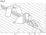
- the invention is described more particularly in the context of its application to a mooring cable such as that shown in figures 1 And 2 .
- the mooring cable is an assembly of 1 strands.
- the cable is shown wound around a support 6. It is then not in use.
- the cable is put into service and deployed on a platform 5.
- the cable has one end forming a loop 12 engaged on a pulley 4 attached to the platform 5.
- the cable has a submerged portion practically over its entire length.
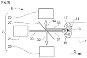
- Set E comprises a strand assembly 1 and a diagnostic device 2.
- the assembly 1 of strands comprises diagnostic fibers 13.
- Each diagnostic fiber 13 is light-conducting. In other words, each fiber is transparent at least for certain light wavelengths. The light propagates in the diagnostic fiber 13 between an input end 15 and an output end 17.
- the diagnostic fiber 13 is made of transparent nylon.
- the diagnostic fiber 13 may be made of polymethyl methacrylate, commonly abbreviated as “PMMA” derived from the English term “polymethyl methacrylate”.
- Each diagnostic fiber 13 has a mechanical tensile strength identical to that of the strands 11. In an example not forming part of the invention, the diagnostic fiber 13 has a mechanical tensile strength equal to that of one of the strands 11 to within 5%.
- the diagnostic fibers 13 are strands 11 of the assembly 1 themselves. This is possible when the strands 11 are light conductors at least for certain light wavelengths, as is the case for example for strands 11 made of transparent nylon.
- some of the strands 11 of the assembly 1 are both designed to undergo tensile forces and at the same time used for the diagnosis of the mechanical state of the strand 11 itself and thus detect any degradation via measurements of light intensity inside the light-conducting strand 11.
- the diagnostic fibers 13 are optical fibers distinct from the strands 11 of the assembly 1.
- the diagnostic fibers 13 extend over the entire length of the assembly 1 of strands.
- the diagnostic device 2 comprises a light source 21, a first optical sensor 23, a second optical sensor 25 and a separating blade 27.
- the light source 21 emits a primary light beam 30.
- the light source is for example a laser.
- the light beam 31 entering the diagnostic fiber 13 is then spatially and temporally coherent.
- the light source 21 may be a lamp or a light-emitting diode, a term commonly abbreviated as “DEL” in French or “LED” in English.
- the splitter blade 27 and beam splitter cube is arranged to separate the primary light beam 30 from the light source 21 into a first beam 31 sent into the diagnostic fiber 13 at the input end 15 and a second beam 32 sent into the second optical sensor 25.
- the light beam 31 is sent into the diagnostic fiber 13. A portion of the light beam 31 propagates in the diagnostic fiber 13 and emerges in the form of an output beam 33.
- the splitter plate 27 intercepts the output beam 33. A portion of the output beam 33 is reflected in the form of a measuring beam 34.
- the measuring beam 34 enters the first optical sensor 23.
- the first optical sensor 23 is capable of providing a signal representative of the light intensity in the output end 17 of the diagnostic fiber 13.
- the first optical sensor 23 is for example a photo-detector such as a photodiode or a camera coupled to an image processing device.
- the light intensity in the output end 17 of the diagnostic fiber 13 is correlated with the mechanical condition of the diagnostic fiber 13.
- the light intensity measured in the output end 17 is maximum, when the diagnostic fiber 13 is broken, the light intensity measured in the output end 17 is zero and when the diagnostic fiber 13 is damaged, the light intensity measured in the output end 17 has an intermediate value between the maximum value and the zero value.
- the second optical sensor 25 is capable of providing a signal representative of the light intensity of the second beam 32.
- the second optical sensor 25 is for example a photo-detector such as a photodiode.
- the second optical sensor 25 makes it possible to detect a failure of the light source 21.
- the second optical sensor 25 makes it possible to determine the cause of an intensity measurement by the first optical sensor 23 below the maximum value. This cause is either a failure of the light source 21 or a deterioration of the diagnostic fiber 13.
- the second optical sensor 25 makes it possible to avoid wrongly detecting a deterioration of the diagnostic fiber 13.
- the assembly 1 of strands 11 is a partially submerged cable
- the electronic components of the diagnostic device 2 such as the light source 21, the first optical sensor 23, and the second optical sensor 25 to be placed at an emerged end of the cable to limit deterioration of the electronic components by water, in particular by sea water.
- the input end 15 and the output end 17 of the diagnostic fibers 13 must both be placed in an emerged end of the cable.
- the input end 15 and the output end 17 of the diagnostic fibers 13 are placed in the loop 12.
- the diagnostic device 2 can also be integrated into the loop 12 shown.
- THE figures 5 And 6 respectively illustrate two embodiments of the invention in which the input end 15 and the output end 17 of the diagnostic fibers 13 are both placed at the same end of the cable.
- the input end 15 and the output end 17 are one and the same end of the diagnostic fiber 13.
- the diagnostic fiber 13 has a distal end 19 opposite the input end 15.
- the distal end 19 is arranged to reflect light into the diagnostic fiber 13.
- the distal end 19 has a straight cleavage allowing Fresnel reflection of an incident beam 36 into a reflected beam 37.
- the light source 21 sends a light beam 31 into the diagnostic fiber 13 at the input end 15, the incident beam 36 corresponds to a portion of the light beam 31 having entered the diagnostic fiber 13. Then, the incident beam 36 is reflected into a reflected beam 37. A portion of the reflected beam 37 exits the diagnostic fiber 13 at the output end 17 as the output beam 33.
- the diagnostic fiber 13 is folded in two so that the input end 15 and the output end 17 are juxtaposed. More generally, all the strands of the assembly of the Figure 7 are folded into two parts and the assembly comprises a first portion 16 comprising all of the first parts of the strands and a second portion 18 comprising all of the second parts of the strands.
- the light source 21 sends a light beam 31 into the diagnostic fiber 13 at the input end 15, the incident beam 36 corresponds to a part of the light beam 31 having penetrated into the fiber 13. Then, the incident beam 36 propagates to the output end 17. A part of the incident beam exits the fiber 13 at the output end 17 in the form of the output beam 33.
- the input end 15 and the output end 17 are at two separate ends of the strand assembly.
- the first optical sensor 23, located at the output end 17, is remote from the rest of the components of the diagnostic device 2, located at the input end 15. Data communication may be established between the first optical sensor 23 and some of the other components of the diagnostic device 2.
- the first optical sensor 23 is a camera.
- the Figure 7 represents an image 10 of one end of a bundle of strands given by the camera.
- the fibers of diagnostics are the strands themselves.
- Image 10 has white dots 110 corresponding to intact strands, gray dots 112 corresponding to damaged strands and black dots 114 corresponding to broken strands.
- Image 10 makes it possible to know the precise mechanical state of a strand assembly in a reliable and efficient manner.
- the data provided by the diagnostic device 2 can make it possible to determine a lifetime of the strand assembly, for example by analyzing the image 10 according to predefined criteria. These criteria can be the rate of intact strands, the rate of damaged strands and the rate of broken strands.
- the diagnostic device 2 comprises a power supply.
- the power supply may be a battery.
- the diagnostic device 2 may comprise a waterproof housing to protect the electronic and optical components of the diagnostic device 2.
- the assembly E may comprise a communication module programmed to transmit the signal from the optical sensor(s) 23, 25 to a remote control unit.
- the data may be transmitted by means of acoustic waves or electrical cables. This allows remote diagnosis of a strand assembly. The diagnosis may be carried out in real time.
Landscapes
- Physics & Mathematics (AREA)
- General Physics & Mathematics (AREA)
- Engineering & Computer Science (AREA)
- Chemical & Material Sciences (AREA)
- Mechanical Engineering (AREA)
- Ocean & Marine Engineering (AREA)
- Combustion & Propulsion (AREA)
- Analytical Chemistry (AREA)
- Aviation & Aerospace Engineering (AREA)
- Investigating Materials By The Use Of Optical Means Adapted For Particular Applications (AREA)
- Investigating Or Analysing Materials By Optical Means (AREA)
- Force Measurement Appropriate To Specific Purposes (AREA)
- Length Measuring Devices By Optical Means (AREA)
Description
- La présente invention concerne le domaine de la détection de dégradations dans un assemblage de brins.
- L'invention trouve une application privilégiée dans le domaine des câbles immergés comme les câbles d'amarrage et permet de détecter une rupture du câble ou une dégradation des performances mécaniques de ce dernier.
- Cependant, l'invention ne se limite pas à un tel domaine d'application et se rapporte, de manière générale, aux matériaux comportant un assemblage de brins, les brins s'étendant principalement dans une direction dite de tension selon laquelle l'assemblage de brins est destiné à subir des efforts de tension. Ainsi, l'invention peut s'appliquer aux cordages, aux bandes de tissu, aux sangles ou aux matériaux composites.
- L'invention concerne plus particulièrement un ensemble comportant un assemblage de brins et un dispositif de diagnostic de l'état de l'assemblage de brins.
- Les câbles d'amarrage ou d'ancrage sont des structures immergées dont l'état mécanique ne peut pas être contrôlé à l'œil nu lorsqu'ils sont en cours d'utilisation.
- Il est connu d'insérer une fibre optique en silice dans un câble et de coupler ce câble avec un dispositif de diagnostic. Le dispositif de diagnostic comporte une source lumineuse agencée pour envoyer un faisceau lumineux se propageant dans la fibre et un capteur optique apte à fournir un signal représentatif de l'intensité lumineuse du faisceau en sortie de la fibre optique. Ainsi, le dispositif de diagnostic permet de détecter une rupture de la fibre optique lorsque l'intensité lumineuse mesurée est nulle.
- Cependant, la silice est un matériau qui présente une faible résistance mécanique en tension. Les brins d'un câble d'amarrage sont réalisés dans un matériau présentant une résistance mécanique en tension bien supérieure à celle de la silice. Ainsi, l'état d'une fibre optique en silice intégrée dans un câble d'amarrage n'est pas représentatif de l'état des brins structurels du câble. Il en résulte un manque de fiabilité et de performance des dispositifs de diagnostic de l'état d'un câble de l'art antérieur.
- Les documents
US2002/088931 ,US2005/226584 ,US2003/154802 ,US2014/305744 ,JPS61104237 US6127672 donnent des exemples de dispositifs de mesures dans des brins flexibles. - L'invention propose un ensemble comportant un assemblage de brins selon la revendication 1.
- Selon d'autres caractéristiques de l'invention :
- l'extrémité d'entrée et l'extrémité de sortie sont une seule et même extrémité de la fibre de diagnostic et la fibre de diagnostic comporte une extrémité distale opposée à l'extrémité d'entrée et réfléchissant la lumière à l'intérieur de la fibre de diagnostic,
- la fibre de diagnostic est pliée en deux de sorte que l'extrémité d'entrée et l'extrémité de sortie sont juxtaposées,
- le dispositif de diagnostic comporte en outre un deuxième capteur optique, et une lame séparatrice agencée pour séparer un faisceau lumineux issu de la source lumineuse en un premier faisceau envoyé dans la fibre de diagnostic et un deuxième faisceau envoyé dans le deuxième capteur optique
- l'assemblage de brins comporte plusieurs fibres de diagnostic, et le premier capteur optique est une caméra générant des images des extrémités de sortie des fibres de diagnostic,
- l'ensemble comporte un module de communication programmé pour transmettre le signal du ou des capteurs optiques à une unité de contrôle distante.
- D'autres caractéristiques et avantages de l'invention apparaitront au cours de la lecture de la description détaillée qui va suivre pour la compréhension de laquelle on se reportera aux dessins annexés dans lesquels :
- [
Fig.1 ] - lafigure 1 est une vue en perspective d'un câble d'amarrage enroulé ; - [
Fig.2 ] - lafigure 2 est une vue en perspective d'une extrémité du câble d'amarrage de lafigure 1 une fois celle-ci attachée à une barge flottante ; - [
Fig.3 ] - lafigure 3 est un schéma fonctionnel d'un ensemble selon un mode de réalisation de l'invention ; - [
Fig.4 ] - lafigure 4 est une vue schématique en perspective d'une coupe transversale d'un assemblage de brins selon un mode de réalisation ne faisant pas partie de l'invention ; - [
Fig.5 ] - lafigure 5 est une vue schématique en perspective d'un assemblage de brins selon un premier mode de réalisation de l'invention ; - [
Fig.6 ] - lafigure 6 est une vue schématique en perspective d'un assemblage de brins selon un deuxième mode de réalisation de l'invention ; - [
Fig.7 ] - lafigure 7 est une image d'une extrémité d'un assemblage de brins donnée par une caméra d'un dispositif de diagnostic selon un mode de réalisation de l'invention. - Dans la description qui va suivre, des éléments identiques, similaires ou analogues seront désignés par les mêmes chiffres de référence.
- L'invention est décrite plus particulièrement dans le cadre de son application à un câble d'amarrage tel que celui représenté en
figures 1 et2 . - Le câble d'amarrage constitue un assemblage 1 de brins. A la
figure 1 , le câble est représenté enroulé autour d'un support 6. Il n'est alors pas en service. A lafigure 2 , le câble est mis en service et déployé sur une plateforme 5. Le câble comporte une extrémité formant une boucle 12 engagée sur une poulie 4 attachée à la plateforme 5. En service, le câble comporte une portion immergée pratiquement sur toute sa longueur. - Cependant, comme mentionné plus haut, d'autres exemples ne faisant pas partie de l'invention peuvent s'appliquer aux cordages, aux bandes de tissu, aux sangles ou aux matériaux composites.
- Il est fait maintenant référence aux
figures 3 et4 pour décrire un ensemble E. - L'ensemble E comporte un assemblage 1 de brins et un dispositif de diagnostic 2.
- L'assemblage 1 comporte des brins 11 réalisés dans un même matériau. Les brins 11 s'étendent principalement dans une direction D de tension selon laquelle l'assemblage 1 de brins 11 est destiné à subir des efforts de tension. Les brins 11 peuvent être maintenus ensemble de différentes manières. Les brins peuvent être :
- tortillés et/ou tressés ensemble,
- tissés ensemble,
- liés ensemble, par exemple par une gaine,
- collés ensemble, par exemple par un polymère thermodurcissable ou thermoplastique.
- Selon une caractéristique particulière de l'invention, l'assemblage 1 de brins comporte des fibres de diagnostic 13.
- Chaque fibre de diagnostic 13 est conductrice de lumière. En d'autres termes, chaque fibre est transparente au moins pour certaines longueurs d'ondes lumineuses. La lumière se propage dans la fibre de diagnostic 13 entre une extrémité d'entrée 15 et une extrémité de sortie 17.
- La fibre de diagnostic 13 est en nylon transparent. En variante, la fibre de diagnostic 13 peut être réalisée en poly-méthacrylate de méthyle, communément abrégé en « PMMA » dérivé du terme anglais « poly-methyl methacrylate ».
- Les fibres de diagnostic 13 s'étendent principalement selon la direction D de tension. Les fibres de diagnostic 13 sont intégrées dans l'assemblage 1 de la même manière que les brins 11. Les fibres peuvent être :
- tortillés et/ou tressés avec les brins 11,
- tissés avec les brins 11,
- liés avec les brins 11, par exemple par une gaine,
- collés avec les brins, par exemple par un polymère thermodurcissable ou thermoplastique.
- Chaque fibre de diagnostic 13 a une résistance mécanique en tension identique à celle des brins 11. Dans un exemple ne faisant pas partie de l'invention, la fibre de diagnostic 13 a une résistance mécanique en tension égale à celle d'un des brins 11 à 5% près.
- Selon l'invention, les fibres de diagnostic 13 sont des brins 11 de l'assemblage 1 eux-mêmes. Ceci est possible lorsque les brins 11 sont conducteurs de lumière au moins pour certaines longueurs d'ondes lumineuses, comme c'est le cas par exemple pour des brins 11 réalisés en nylon transparent.
- Dans ce cas, certains des brins 11 de l'assemblage 1 sont à la fois conçus pour subir des efforts de tension et à la fois utilisés pour le diagnostic de l'état mécanique du brin 11 lui-même et ainsi détecter une quelconque dégradation via des mesures d'intensité lumineuse à l'intérieur du brin 11 conducteur de lumière.
- Selon un exemple ne faisant pas partie de l'invention, les fibres de diagnostic 13 sont des fibres optiques distinctes des brins 11 de l'assemblage 1. Les fibres de diagnostic 13 s'étendent sur toute la longueur de l'assemblage 1 de brins.
- Le dispositif de diagnostic 2 comporte une source lumineuse 21, un premier capteur optique 23, un deuxième capteur optique 25 et une lame séparatrice 27.
- La source lumineuse 21 émet un faisceau lumineux primaire 30.
- La source lumineuse est par exemple un laser. Le faisceau lumineux 31 entrant dans la fibre de diagnostic 13 est alors spatialement et temporellement cohérent.
- En variante, la source lumineuse 21 peut être une lampe ou une diode électroluminescente, terme communément abrégé en « DEL » en Français ou en « LED » en anglais.
- La lame séparatrice 27 et cube séparateur de faisceau est agencée pour séparer le faisceau lumineux primaire 30 issu de la source lumineuse 21 en un premier faisceau 31 envoyé dans la fibre de diagnostic 13 au niveau de l'extrémité d'entrée 15 et un deuxième faisceau 32 envoyé dans le deuxième capteur optique 25.
- Le faisceau lumineux 31 est envoyé dans la fibre de diagnostic 13. Une partie du faisceau lumineux 31 se propage dans la fibre de diagnostic 13 et ressort sous forme d'un faisceau de sortie 33. La lame séparatrice 27 intercepte le faisceau de sortie 33. Une part du faisceau de sortie 33 est réfléchi sous forme d'un faisceau de mesure 34. Le faisceau de mesure 34 pénètre dans le premier capteur optique 23.
- Le premier capteur optique 23 est apte à fournir un signal représentatif de l'intensité lumineuse dans l'extrémité de sortie 17 de la fibre de diagnostic 13. Le premier capteur optique 23 est par exemple un photo-détecteur comme une photodiode ou une caméra couplée à un dispositif de traitement d'image.
- L'intensité lumineuse dans l'extrémité de sortie 17 de la fibre de diagnostic 13 est corrélée à l'état mécanique de la fibre de diagnostic 13. Lorsque la fibre de diagnostic 13 est en bon état, l'intensité lumineuse mesurée dans l'extrémité de sortie 17 est maximale, lorsque la fibre de diagnostic 13 est rompue, l'intensité lumineuse mesurée dans l'extrémité de sortie 17 est nulle et lorsque la fibre de diagnostic 13 est endommagée, l'intensité lumineuse mesurée dans l'extrémité de sortie 17 a une valeur intermédiaire entre la valeur maximale et la valeur nulle.
- Le deuxième capteur optique 25 est apte à fournir un signal représentatif de l'intensité lumineuse du deuxième faisceau 32. Le deuxième capteur optique 25 est par exemple un photo-détecteur comme une photodiode.
- Le deuxième capteur optique 25 permet de détecter une défaillance de la source lumineuse 21. En particulier, le deuxième capteur optique 25 permet de déterminer la cause d'une mesure d'intensité par le premier capteur optique 23 inférieure à la valeur maximale. Cette cause est soit une défaillance de la source lumineuse 21, soit une détérioration de la fibre de diagnostic 13. Le deuxième capteur optique 25 permet d'éviter de détecter à tort une détérioration de la fibre de diagnostic 13.
- Lorsque l'assemblage 1 de brins 11 est un câble partiellement immergé, il est avantageux que les composants électroniques du dispositif de diagnostic 2 tels que la source lumineuse 21, le premier capteur optique 23, et le deuxième capteur optique 25 soient placés à une extrémité émergée du câble pour limiter la détérioration des composants électroniques par l'eau, notamment par l'eau de mer. Dans ce cas, l'extrémité d'entrée 15 et l'extrémité de sortie 17 des fibres de diagnostic 13 doivent être placées toutes deux dans une extrémité émergé du câble.
- Dans l'exemple des
figures 1 et2 , l'extrémité d'entrée 15 et l'extrémité de sortie 17 des fibres de diagnostic 13 sont placées dans la boucle 12. Le dispositif de diagnostic 2 peut être également intégré dans la boucle 12 représentée. - Les
figures 5 et6 illustrent respectivement deux modes de réalisation de l'invention dans lesquels l'extrémité d'entrée 15 et l'extrémité de sortie 17 des fibres de diagnostic 13 sont placées toutes deux à une même extrémité du câble. - A la
figure 5 , l'extrémité d'entrée 15 et l'extrémité de sortie 17 sont une seule et même extrémité de la fibre de diagnostic 13. La fibre de diagnostic 13 comporte une extrémité distale 19 opposée à l'extrémité d'entrée 15. - L'extrémité distale 19 est agencée pour réfléchir la lumière à l'intérieur de la fibre de diagnostic 13. Par exemple, l'extrémité distale 19 présente un clivage droit permettant une réflexion de Fresnel d'un faisceau incident 36 en un faisceau réfléchi 37. La source lumineuse 21 envoie un faisceau lumineux 31 dans la fibre de diagnostic 13 au niveau de l'extrémité d'entrée 15, le faisceau incident 36 correspond à une partie du faisceau lumineux 31 ayant pénétré dans la fibre de diagnostic 13. Ensuite, le faisceau incident 36 est réfléchi en un faisceau réfléchi 37. Une partie du faisceau réfléchi 37 sort de la fibre de diagnostic 13 au niveau de l'extrémité de sortie 17 sous forme du faisceau de sortie 33.
- A la
figure 6 , la fibre de diagnostic 13 est pliée en deux de sorte que l'extrémité d'entrée 15 et l'extrémité de sortie 17 sont juxtaposées. Plus généralement, tous les brins de l'assemblage de lafigure 7 sont pliés en deux parties et l'assemblage comporte une première portion 16 comportant l'ensemble des premières parties des brins et une deuxième portion 18 comportant l'ensemble des deuxièmes parties des brins. La source lumineuse 21 envoie un faisceau lumineux 31 dans la fibre de diagnostic 13 au niveau de l'extrémité d'entrée 15, le faisceau incident 36 correspond à une partie du faisceau lumineux 31 ayant pénétré dans la fibre 13. Ensuite, le faisceau incident 36 se propage jusqu'à l'extrémité de sortie 17. Une partie du faisceau incident sort de la fibre 13 au niveau de l'extrémité de sortie 17 sous forme du faisceau de sortie 33. - En variante, l'extrémité d'entrée 15 et l'extrémité de sortie 17 sont à deux extrémités distinctes de l'assemblage de brins. Dans ce cas, le premier capteur optique 23, situé à l'extrémité de sortie 17, est distant du reste des composants du dispositif de diagnostic 2, situés à l'extrémité d'entrée 15. Une communication de données peut être établie entre le premier capteur optique 23 et certains des autres composants du dispositif de diagnostic 2.
- Dans l'exemple de la
figure 7 , le premier capteur optique 23 est une caméra. Lafigure 7 représente une image 10 d'une extrémité d'un assemblage de brins donnée par la caméra. Dans cet assemblage de brins, les fibres de diagnostics sont les brins eux-mêmes. L'image 10 comporte des points blancs 110 correspondant à des brins intacts, des points grisés 112 correspondant à des brins endommagés et des points noirs 114 correspondant à des brins rompus. L'image 10 permet de connaître l'état mécanique précis d'un assemblage de brins de manière fiable et performante. - Les données fournies par le dispositif de diagnostic 2 peuvent permettre de déterminer une durée de vie de l'assemblage de brins, par exemple grâce à une analyse de l'image 10 en fonction de critères prédéfinis. Ces critères peuvent être le taux de brins intacts, le taux de brins endommagés et le taux de brins rompus.
- Le dispositif de diagnostic 2 comporte une alimentation électrique. Pour permettre une autonomie du dispositif de diagnostic 2, l'alimentation électrique peut être une batterie. Le dispositif de diagnostic 2 peut comporter un boîtier étanche permettant de de protéger les composants électroniques et optiques du dispositif de diagnostic 2.
- L'ensemble E peut comporter un module de communication programmé pour transmettre le signal du ou des capteurs optiques 23, 25 à une unité de contrôle distante. Les données peuvent être transmises au moyen d'ondes acoustiques ou de câbles électriques. Ceci permet de réaliser un diagnostic à distance d'un assemblage de brins. Le diagnostic peut être réalisé en temps réel.
- On comprendra que diverses modifications et/ou améliorations évidentes pour l'homme du métier peuvent être apportées aux différents modes de réalisation de l'invention décrits ou évoqués dans la présente description sans sortir du cadre de de l'invention défini par les revendications annexées.
Claims (6)
- Ensemble (E) comportant un assemblage (1) de brins (11) constituant un câble d'amarrage et/ou d'ancrage,les brins (11) s'étendant principalement dans une direction D dite de tension selon laquelle l'assemblage (1) de brins (11) est destiné à subir des efforts de tension,caractérisé en ce que tous les brins (11) constituant l'assemblage (1) sont réalisés dans un même matériau avec la même résistance mécanique en tension,les brins (11) sont en nylon transparent et conducteurs de lumière au moins pour certaines longueurs d'ondes lumineuses,en ce qu'au moins un brin (11) de l'assemblage (1) constitue une fibre (13) de diagnostic de sorte que la fibre (13) de diagnostic est conductrice de lumière, la lumière se propageant dans la fibre (13) de diagnostic entre une extrémité d'entrée (15) et une extrémité de sortie (17),et en ce que l'ensemble (E) comprend un dispositif de diagnostic (2) comportant :- une source lumineuse (21) agencée pour envoyer un faisceau lumineux (31) dans la fibre (13) de diagnostic au niveau de l'extrémité d'entrée (15),- un premier capteur optique (23) apte à fournir un signal représentatif de l'intensité lumineuse dans l'extrémité de sortie (17) de la fibre (13) de diagnostic, l'intensité lumineuse dans l'extrémité de sortie (17) de la fibre (13) de diagnostic étant corrélée à l'état mécanique de la fibre (13) de diagnostic.
- Ensemble (E) selon l'une quelconque des revendications précédentes, caractérisé en ce que l'extrémité d'entrée (15) et l'extrémité de sortie (17) sont une seule et même extrémité de la fibre (13) de diagnostic et en ce que la fibre (13) de diagnostic comporte une extrémité distale (19) opposée à l'extrémité d'entrée (15) et réfléchissant la lumière à l'intérieur de la fibre (13) de diagnostic.
- Ensemble (E) selon la revendication 1, caractérisé en ce que la fibre (13) de diagnostic est pliée en deux de sorte que l'extrémité d'entrée (15) et l'extrémité de sortie (17) sont juxtaposées.
- Ensemble (E) selon l'une quelconque des revendications précédentes, caractérisé en ce que le dispositif de diagnostic (2) comporte en outre :- un deuxième capteur optique (25), et- une lame séparatrice (27) agencée pour séparer un faisceau lumineux (30) issu de la source lumineuse (21) en un premier faisceau (31) envoyé dans la fibre (13) de diagnostic et un deuxième faisceau (32) envoyé dans le deuxième capteur optique (25).
- Ensemble (E) selon l'une quelconque des revendications précédentes, caractérisé :- en ce que l'assemblage (1) de brins (11) comporte plusieurs fibres (13) de diagnostic, et- en ce que le premier capteur optique (23) est une caméra générant des images des extrémités de sortie (17) des fibres (13) de diagnostic.
- Ensemble (E) selon l'une quelconque des revendications précédentes, caractérisé en ce qu'il comporte un module de communication programmé pour transmettre le signal du ou des capteurs optiques (23, 25) à une unité de contrôle distante.
Applications Claiming Priority (2)
| Application Number | Priority Date | Filing Date | Title |
|---|---|---|---|
| FR2002686A FR3108405B1 (fr) | 2020-03-19 | 2020-03-19 | Ensemble comportant un assemblage de brins et un dispositif de diagnostic de l’etat de l’assemblage de brins |
| PCT/FR2021/050367 WO2021186117A1 (fr) | 2020-03-19 | 2021-03-04 | Ensemble comportant un assemblage de brins et un dispositif de diagnostic de l'etat de l'assemblage de brins |
Publications (2)
| Publication Number | Publication Date |
|---|---|
| EP4121730A1 EP4121730A1 (fr) | 2023-01-25 |
| EP4121730B1 true EP4121730B1 (fr) | 2025-06-04 |
Family
ID=70804787
Family Applications (1)
| Application Number | Title | Priority Date | Filing Date |
|---|---|---|---|
| EP21714650.5A Active EP4121730B1 (fr) | 2020-03-19 | 2021-03-04 | Ensemble comportant un assemblage de brins et un dispositif de diagnostic de l'etat de l'assemblage de brins |
Country Status (5)
| Country | Link |
|---|---|
| US (1) | US20230142511A1 (fr) |
| EP (1) | EP4121730B1 (fr) |
| CN (1) | CN115667866A (fr) |
| FR (1) | FR3108405B1 (fr) |
| WO (1) | WO2021186117A1 (fr) |
Family Cites Families (14)
| Publication number | Priority date | Publication date | Assignee | Title |
|---|---|---|---|---|
| JPS61104237A (ja) * | 1984-10-26 | 1986-05-22 | Nippon Telegr & Teleph Corp <Ntt> | 光ケ−ブルの曲げによる光フアイバひずみの測定装置および測定方法 |
| JPH01203906A (ja) * | 1988-02-10 | 1989-08-16 | Brother Ind Ltd | 光ファイバセンサ装置 |
| US5031987A (en) * | 1990-01-02 | 1991-07-16 | Sundstrand Data Control, Inc. | Fiber optic thermal switch utilizing frustrated total internal reflection readout |
| US5182449A (en) * | 1990-02-06 | 1993-01-26 | The Boeing Corporation | System and method for structural monitoring using optical imaging of fiber sensors |
| US6127672A (en) * | 1997-05-23 | 2000-10-03 | Canadian Space Agency | Topological and motion measuring tool |
| GB0014936D0 (en) * | 2000-06-20 | 2000-08-09 | Univ Strathclyde | Strain transducer |
| US6563107B2 (en) * | 2001-01-11 | 2003-05-13 | Canadian Space Agency | Topological and motion measuring tool |
| ATE525627T1 (de) * | 2001-12-27 | 2011-10-15 | Prysmian Spa | Online-spannungsmessung in einer optischen faser |
| US6999641B2 (en) * | 2002-05-03 | 2006-02-14 | Jerry Gene Williams | Measurement of large strains in ropes using plastic optical fibers |
| US8277119B2 (en) * | 2006-12-19 | 2012-10-02 | Vibrosystm, Inc. | Fiber optic temperature sensor |
| FI124486B (fi) * | 2012-01-24 | 2014-09-30 | Kone Corp | Nostolaitteen köysi, köysijärjestely, hissi ja nostolaitteen köyden kunnonvalvontamenetelmä |
| US20150197408A1 (en) * | 2014-01-15 | 2015-07-16 | Slingmax, Inc. | Rope pre-failure warning indicator system and method |
| US9521885B2 (en) * | 2014-05-30 | 2016-12-20 | Apple Inc. | Woven display |
| KR101762654B1 (ko) * | 2015-09-09 | 2017-07-28 | 삼성중공업 주식회사 | 무어링체인의 모니터링 로봇 |
-
2020
- 2020-03-19 FR FR2002686A patent/FR3108405B1/fr active Active
-
2021
- 2021-03-04 CN CN202180033373.7A patent/CN115667866A/zh active Pending
- 2021-03-04 WO PCT/FR2021/050367 patent/WO2021186117A1/fr not_active Ceased
- 2021-03-04 US US17/912,780 patent/US20230142511A1/en active Pending
- 2021-03-04 EP EP21714650.5A patent/EP4121730B1/fr active Active
Also Published As
| Publication number | Publication date |
|---|---|
| CN115667866A (zh) | 2023-01-31 |
| US20230142511A1 (en) | 2023-05-11 |
| EP4121730A1 (fr) | 2023-01-25 |
| FR3108405A1 (fr) | 2021-09-24 |
| FR3108405B1 (fr) | 2022-04-15 |
| WO2021186117A1 (fr) | 2021-09-23 |
Similar Documents
| Publication | Publication Date | Title |
|---|---|---|
| JP5052530B2 (ja) | 現場取付け可能なメカニカルスプライス型コネクタ用一体形視覚的障害点測定器付き取付け工具 | |
| FR2521727A2 (fr) | Dispositif pour mesurer l'etat d'oxydo-reduction d'un organe vivant in situ | |
| FR2703160A1 (fr) | Cassette pour dispositif à fibres optiques, équipée d'un faisceau de tubes souples de protection des fibres. | |
| FR2700021A1 (fr) | Appareil de libération des contraintes d'une fibre optique. | |
| FR2751746A1 (fr) | Procede et dispositif de mesure par reflectometrie pour connexion de fibre optique | |
| EP0282766A1 (fr) | Embase active de connecteur optique | |
| EP0018873B1 (fr) | Dispositif compact de couplage optique et gyromètre interferométrique à fibre optique comportant un tel dispositif | |
| EP0083527B1 (fr) | Dispositif de couplage entre une source lumineuse à rayonnement divergent et une fibre optique | |
| FR2563627A1 (fr) | Procede et appareil pour l'eclairage en retour de connecteurs optiques | |
| FR2653621A1 (fr) | Localisateur de defauts optiques a haute resolution et procede de fabrication d'un coupleur multimode mis en óoeuvre dans ce localisateur. | |
| EP4121730A1 (fr) | Ensemble comportant un assemblage de brins et un dispositif de diagnostic de l'etat de l'assemblage de brins | |
| FR2575557A1 (fr) | Dispositif transformateur d'ouverture numerique | |
| EP0064919A1 (fr) | Dispositif extracteur et/ou réinjecteur de signal optique | |
| EP0844472B1 (fr) | Dispositif pour la détection d'un dommage dans une fibre optique | |
| EP4515199B1 (fr) | Dispositif de detection d'un defaut dans un element structurel en materiau composite | |
| EP1024353A1 (fr) | Procédé pour déterminer par réflectométrie, une caractéristique d'une fibre optique | |
| FR2517835A1 (fr) | Perfectionnements apportes aux conducteurs d'image | |
| EP3994430B1 (fr) | Dispositif de mesure comprenant une fibre optique de connexion et un équipement de mesure pour l'instrumentation d'un appareillage aéronautique, et un appareillage aéronautique comprenant un tel dispositif de mesure | |
| FR2566139A1 (fr) | Dispositif de distribution d'energie lumineuse et son utilisation a la commutation optique | |
| FR3101195A1 (fr) | Liaison électrique comprenant un dispositif optronique de protection électrique. | |
| EP4425142B1 (fr) | Système et procédé d'identification et de vérification d'une liaison par fibre optique | |
| FR2567651A1 (fr) | Equipement de mesure de vitesse d'un projectile par interferometrie utilisant un faisceau laser propage par un guide d'onde optique unique | |
| FR2676814A1 (fr) | Systeme de surveillance et de controle des cables par fibre optique. | |
| EP0120764A1 (fr) | Séparateur de faisceaux d'ondes optiques | |
| FR2734373A1 (fr) | Coupleur optique a taux de derivation variable et utilisation en tant que capteur |
Legal Events
| Date | Code | Title | Description |
|---|---|---|---|
| STAA | Information on the status of an ep patent application or granted ep patent |
Free format text: STATUS: UNKNOWN |
|
| STAA | Information on the status of an ep patent application or granted ep patent |
Free format text: STATUS: THE INTERNATIONAL PUBLICATION HAS BEEN MADE |
|
| PUAI | Public reference made under article 153(3) epc to a published international application that has entered the european phase |
Free format text: ORIGINAL CODE: 0009012 |
|
| STAA | Information on the status of an ep patent application or granted ep patent |
Free format text: STATUS: REQUEST FOR EXAMINATION WAS MADE |
|
| 17P | Request for examination filed |
Effective date: 20220915 |
|
| AK | Designated contracting states |
Kind code of ref document: A1 Designated state(s): AL AT BE BG CH CY CZ DE DK EE ES FI FR GB GR HR HU IE IS IT LI LT LU LV MC MK MT NL NO PL PT RO RS SE SI SK SM TR |
|
| DAV | Request for validation of the european patent (deleted) | ||
| DAX | Request for extension of the european patent (deleted) | ||
| P01 | Opt-out of the competence of the unified patent court (upc) registered |
Effective date: 20230527 |
|
| GRAP | Despatch of communication of intention to grant a patent |
Free format text: ORIGINAL CODE: EPIDOSNIGR1 |
|
| STAA | Information on the status of an ep patent application or granted ep patent |
Free format text: STATUS: GRANT OF PATENT IS INTENDED |
|
| INTG | Intention to grant announced |
Effective date: 20250122 |
|
| GRAS | Grant fee paid |
Free format text: ORIGINAL CODE: EPIDOSNIGR3 |
|
| GRAA | (expected) grant |
Free format text: ORIGINAL CODE: 0009210 |
|
| STAA | Information on the status of an ep patent application or granted ep patent |
Free format text: STATUS: THE PATENT HAS BEEN GRANTED |
|
| AK | Designated contracting states |
Kind code of ref document: B1 Designated state(s): AL AT BE BG CH CY CZ DE DK EE ES FI FR GB GR HR HU IE IS IT LI LT LU LV MC MK MT NL NO PL PT RO RS SE SI SK SM TR |
|
| REG | Reference to a national code |
Ref country code: GB Ref legal event code: FG4D Free format text: NOT ENGLISH |
|
| REG | Reference to a national code |
Ref country code: CH Ref legal event code: EP |
|
| REG | Reference to a national code |
Ref country code: DE Ref legal event code: R096 Ref document number: 602021031744 Country of ref document: DE |
|
| REG | Reference to a national code |
Ref country code: IE Ref legal event code: FG4D Free format text: LANGUAGE OF EP DOCUMENT: FRENCH |
|
| REG | Reference to a national code |
Ref country code: NL Ref legal event code: MP Effective date: 20250604 |
|
| PG25 | Lapsed in a contracting state [announced via postgrant information from national office to epo] |
Ref country code: FI Free format text: LAPSE BECAUSE OF FAILURE TO SUBMIT A TRANSLATION OF THE DESCRIPTION OR TO PAY THE FEE WITHIN THE PRESCRIBED TIME-LIMIT Effective date: 20250604 Ref country code: ES Free format text: LAPSE BECAUSE OF FAILURE TO SUBMIT A TRANSLATION OF THE DESCRIPTION OR TO PAY THE FEE WITHIN THE PRESCRIBED TIME-LIMIT Effective date: 20250604 |
|
| REG | Reference to a national code |
Ref country code: LT Ref legal event code: MG9D |
|
| PG25 | Lapsed in a contracting state [announced via postgrant information from national office to epo] |
Ref country code: GR Free format text: LAPSE BECAUSE OF FAILURE TO SUBMIT A TRANSLATION OF THE DESCRIPTION OR TO PAY THE FEE WITHIN THE PRESCRIBED TIME-LIMIT Effective date: 20250905 |
|
| PG25 | Lapsed in a contracting state [announced via postgrant information from national office to epo] |
Ref country code: PL Free format text: LAPSE BECAUSE OF FAILURE TO SUBMIT A TRANSLATION OF THE DESCRIPTION OR TO PAY THE FEE WITHIN THE PRESCRIBED TIME-LIMIT Effective date: 20250604 |
|
| PG25 | Lapsed in a contracting state [announced via postgrant information from national office to epo] |
Ref country code: BG Free format text: LAPSE BECAUSE OF FAILURE TO SUBMIT A TRANSLATION OF THE DESCRIPTION OR TO PAY THE FEE WITHIN THE PRESCRIBED TIME-LIMIT Effective date: 20250604 |
|
| PG25 | Lapsed in a contracting state [announced via postgrant information from national office to epo] |
Ref country code: HR Free format text: LAPSE BECAUSE OF FAILURE TO SUBMIT A TRANSLATION OF THE DESCRIPTION OR TO PAY THE FEE WITHIN THE PRESCRIBED TIME-LIMIT Effective date: 20250604 |
|
| PG25 | Lapsed in a contracting state [announced via postgrant information from national office to epo] |
Ref country code: RS Free format text: LAPSE BECAUSE OF FAILURE TO SUBMIT A TRANSLATION OF THE DESCRIPTION OR TO PAY THE FEE WITHIN THE PRESCRIBED TIME-LIMIT Effective date: 20250904 |
|
| PG25 | Lapsed in a contracting state [announced via postgrant information from national office to epo] |
Ref country code: LV Free format text: LAPSE BECAUSE OF FAILURE TO SUBMIT A TRANSLATION OF THE DESCRIPTION OR TO PAY THE FEE WITHIN THE PRESCRIBED TIME-LIMIT Effective date: 20250604 |
|
| PG25 | Lapsed in a contracting state [announced via postgrant information from national office to epo] |
Ref country code: NL Free format text: LAPSE BECAUSE OF FAILURE TO SUBMIT A TRANSLATION OF THE DESCRIPTION OR TO PAY THE FEE WITHIN THE PRESCRIBED TIME-LIMIT Effective date: 20250604 |
|
| PG25 | Lapsed in a contracting state [announced via postgrant information from national office to epo] |
Ref country code: PT Free format text: LAPSE BECAUSE OF FAILURE TO SUBMIT A TRANSLATION OF THE DESCRIPTION OR TO PAY THE FEE WITHIN THE PRESCRIBED TIME-LIMIT Effective date: 20251006 |
|
| REG | Reference to a national code |
Ref country code: AT Ref legal event code: MK05 Ref document number: 1800743 Country of ref document: AT Kind code of ref document: T Effective date: 20250604 |
|
| PG25 | Lapsed in a contracting state [announced via postgrant information from national office to epo] |
Ref country code: IS Free format text: LAPSE BECAUSE OF FAILURE TO SUBMIT A TRANSLATION OF THE DESCRIPTION OR TO PAY THE FEE WITHIN THE PRESCRIBED TIME-LIMIT Effective date: 20251004 |
|
| PG25 | Lapsed in a contracting state [announced via postgrant information from national office to epo] |
Ref country code: SM Free format text: LAPSE BECAUSE OF FAILURE TO SUBMIT A TRANSLATION OF THE DESCRIPTION OR TO PAY THE FEE WITHIN THE PRESCRIBED TIME-LIMIT Effective date: 20250604 Ref country code: AT Free format text: LAPSE BECAUSE OF FAILURE TO SUBMIT A TRANSLATION OF THE DESCRIPTION OR TO PAY THE FEE WITHIN THE PRESCRIBED TIME-LIMIT Effective date: 20250604 |
|
| PG25 | Lapsed in a contracting state [announced via postgrant information from national office to epo] |
Ref country code: CZ Free format text: LAPSE BECAUSE OF FAILURE TO SUBMIT A TRANSLATION OF THE DESCRIPTION OR TO PAY THE FEE WITHIN THE PRESCRIBED TIME-LIMIT Effective date: 20250604 |
|
| PG25 | Lapsed in a contracting state [announced via postgrant information from national office to epo] |
Ref country code: EE Free format text: LAPSE BECAUSE OF FAILURE TO SUBMIT A TRANSLATION OF THE DESCRIPTION OR TO PAY THE FEE WITHIN THE PRESCRIBED TIME-LIMIT Effective date: 20250604 |
|
| PG25 | Lapsed in a contracting state [announced via postgrant information from national office to epo] |
Ref country code: SK Free format text: LAPSE BECAUSE OF FAILURE TO SUBMIT A TRANSLATION OF THE DESCRIPTION OR TO PAY THE FEE WITHIN THE PRESCRIBED TIME-LIMIT Effective date: 20250604 |
|
| PG25 | Lapsed in a contracting state [announced via postgrant information from national office to epo] |
Ref country code: IT Free format text: LAPSE BECAUSE OF FAILURE TO SUBMIT A TRANSLATION OF THE DESCRIPTION OR TO PAY THE FEE WITHIN THE PRESCRIBED TIME-LIMIT Effective date: 20250604 |
|
| REG | Reference to a national code |
Ref country code: DE Ref legal event code: R097 Ref document number: 602021031744 Country of ref document: DE |
|
| PGFP | Annual fee paid to national office [announced via postgrant information from national office to epo] |
Ref country code: GB Payment date: 20260324 Year of fee payment: 6 |
|
| PLBE | No opposition filed within time limit |
Free format text: ORIGINAL CODE: 0009261 |
|
| STAA | Information on the status of an ep patent application or granted ep patent |
Free format text: STATUS: NO OPPOSITION FILED WITHIN TIME LIMIT |
|
| PG25 | Lapsed in a contracting state [announced via postgrant information from national office to epo] |
Ref country code: DK Free format text: LAPSE BECAUSE OF FAILURE TO SUBMIT A TRANSLATION OF THE DESCRIPTION OR TO PAY THE FEE WITHIN THE PRESCRIBED TIME-LIMIT Effective date: 20250604 |
|
| PGFP | Annual fee paid to national office [announced via postgrant information from national office to epo] |
Ref country code: NO Payment date: 20260320 Year of fee payment: 6 |
|
| REG | Reference to a national code |
Ref country code: CH Ref legal event code: L10 Free format text: ST27 STATUS EVENT CODE: U-0-0-L10-L00 (AS PROVIDED BY THE NATIONAL OFFICE) Effective date: 20260416 |
|
| PGFP | Annual fee paid to national office [announced via postgrant information from national office to epo] |
Ref country code: FR Payment date: 20260324 Year of fee payment: 6 |
|
| 26N | No opposition filed |
Effective date: 20260305 |