EP4121601B1 - A heavy-duty barrier - Google Patents
A heavy-duty barrier Download PDFInfo
- Publication number
- EP4121601B1 EP4121601B1 EP21711929.6A EP21711929A EP4121601B1 EP 4121601 B1 EP4121601 B1 EP 4121601B1 EP 21711929 A EP21711929 A EP 21711929A EP 4121601 B1 EP4121601 B1 EP 4121601B1
- Authority
- EP
- European Patent Office
- Prior art keywords
- heavy
- connection element
- duty
- duty barrier
- bar
- Prior art date
- Legal status (The legal status is an assumption and is not a legal conclusion. Google has not performed a legal analysis and makes no representation as to the accuracy of the status listed.)
- Active
Links
Images


Classifications
-
- E—FIXED CONSTRUCTIONS
- E01—CONSTRUCTION OF ROADS, RAILWAYS, OR BRIDGES
- E01F—ADDITIONAL WORK, SUCH AS EQUIPPING ROADS OR THE CONSTRUCTION OF PLATFORMS, HELICOPTER LANDING STAGES, SIGNS, SNOW FENCES, OR THE LIKE
- E01F13/00—Arrangements for obstructing or restricting traffic, e.g. gates, barricades ; Preventing passage of vehicles of selected category or dimensions
- E01F13/02—Arrangements for obstructing or restricting traffic, e.g. gates, barricades ; Preventing passage of vehicles of selected category or dimensions free-standing; portable, e.g. for guarding open manholes ; Portable signs or signals specially adapted for fitting to portable barriers
- E01F13/022—Pedestrian barriers; Barriers for channelling or controlling crowds
-
- E—FIXED CONSTRUCTIONS
- E01—CONSTRUCTION OF ROADS, RAILWAYS, OR BRIDGES
- E01F—ADDITIONAL WORK, SUCH AS EQUIPPING ROADS OR THE CONSTRUCTION OF PLATFORMS, HELICOPTER LANDING STAGES, SIGNS, SNOW FENCES, OR THE LIKE
- E01F13/00—Arrangements for obstructing or restricting traffic, e.g. gates, barricades ; Preventing passage of vehicles of selected category or dimensions
- E01F13/04—Arrangements for obstructing or restricting traffic, e.g. gates, barricades ; Preventing passage of vehicles of selected category or dimensions movable to allow or prevent passage
-
- E—FIXED CONSTRUCTIONS
- E04—BUILDING
- E04H—BUILDINGS OR LIKE STRUCTURES FOR PARTICULAR PURPOSES; SWIMMING OR SPLASH BATHS OR POOLS; MASTS; FENCING; TENTS OR CANOPIES, IN GENERAL
- E04H17/00—Fencing, e.g. fences, enclosures, corrals
- E04H17/013—Fencing, e.g. fences, enclosures, corrals in combination with gates
-
- E—FIXED CONSTRUCTIONS
- E04—BUILDING
- E04H—BUILDINGS OR LIKE STRUCTURES FOR PARTICULAR PURPOSES; SWIMMING OR SPLASH BATHS OR POOLS; MASTS; FENCING; TENTS OR CANOPIES, IN GENERAL
- E04H17/00—Fencing, e.g. fences, enclosures, corrals
- E04H17/14—Fences constructed of rigid elements, e.g. with additional wire fillings or with posts
- E04H17/16—Fences constructed of rigid elements, e.g. with additional wire fillings or with posts using prefabricated panel-like elements, e.g. wired frames
- E04H17/18—Corrals, i.e. easily transportable or demountable enclosures
Definitions
- the present invention relates to the field of heavy-duty barriers, wherein the heavy-duty barrier has a base part of concrete, or which is fillable with concrete, and a fence part attached to the base part, wherein the fence part comprises a bar structure.
- a heavy-duty barrier of the kind relevant for this application is a barrier that is used to prevent people from entering a worksite and that is substantially heavier and more stable, and thereby provides a substantially higher safety, than a simple fence.
- the work is repair, maintenance or construction work on a road or on building, but it can be any activity that necessitates entrance restriction.
- the heavy-duty barrier is supposed to be able to stop a person falling against it without overturning.
- the heavy-duty barrier has a lower part, or base part, which is heavy and constitutes a ballast.
- the base part consists of concrete or of a metal tub filled with concrete, but other solutions exist as well.
- the heavy-duty barrier further comprises an upper part, which acts as a fence and consists of a bar structure.
- the upper part, or fence part is attached to the base part, for instance by having bottom ends cast into the concrete or being attached to the concrete or to the tub.
- heavy-duty barriers are positioned in a row, i.e. side by side, in order to block an area, and then they are interconnected by means of chains attached to their base parts. This possibility to interconnect the barriers is helpful in that it enhances the ability of the barrier to withstand a force trying to move it by pushing on the base part, since one or more other barriers will have to be moved in common with the barrier subjected to the force.
- the heavy-duty barrier is only tested for persons falling against it which is communicated by the manufacturers, users of the heavy-duty barrier often believe that it is capable of withstanding larger forces than a person falling against it without overturning, since it is perceived as heavy and stable. That user perception causes wrong use, which in turn generates a risk of accidents.
- a heavy-duty barrier which is movable, comprising a base part, which comprises a ballast, and a fence part attached to the base part, wherein the fence part comprises a fixed bar structure and a rigid first connection element, which is movably attached to the bar structure, wherein the first connection element comprises an attachment portion, movably attached to a bar portion of the bar structure and encircling the circumference of the bar portion, and a hook portion arranged to be engaged with a complementary hook portion of a rigid connection element of a neighbouring heavy-duty barrier.
- connection element makes them capable of even withstanding a hit by a car. It should be noted that the definition of the connection element as rigid does not exclude flexible or pivotable parts from being included, while the overall structure is still considered to be rigid. This contrasts with a chain, which is considered non-rigid, i.e. flexible, while still including many rigid elements, i.e. the individual links of the chain.
- the movable attachment of the attachment portion includes rotation of the first connection element about a longitudinal centre axis of the bar portion.
- the movable attachment of the attachment portion includes movement along a length of the bar portion. Thereby, accommodation of unevenness of the ground is enhanced.
- the attachment portion is tubular. This provides a simple yet reliable attachment of the connection element to the fixed bar structure.
- the hook portion comprises a first protrusion protruding from the attachment portion, and a second protrusion protruding from the attachment portion, wherein the first and second protrusions define a gap between them, which gap is arranged to receive a part of a first protrusion of the first connection element of a neighbouring heavy-duty barrier.
- the first protrusion has an L-shaped cross-section, and a free end of the first protrusion faces the second protrusion.
- the first connection element is rotatably movable around the bar portion between several rotatably fixed positions. Thereby, the stability of the interconnection of the heavy-duty barriers is further increased.
- the first connection element is arranged to be movable between the fixed positions by means of a combination of longitudinal movement and rotational movement. Thereby, a simple setting of the first connection element in different positions while being securely kept in the fixed position can be obtained.
- the heavy-duty barrier comprises a rotation blocking element fixedly arranged at the bar portion below the first connection element and arranged to engage with the connection element to block rotation thereof.
- the attachment portion comprises first protrusions extending downwards.
- the heavy-duty barrier comprises a rotation blocking element fixedly attached to the bar portion below the first connection element, and the rotation blocking element comprises second protrusions extending upwards and engaging with the first protrusions.
- the attachment portion comprises first protrusions extending downwards and arranged to engage with the bar structure to block rotational movement of the connection element.
- the first connection element is freely rotatable to any position.
- the heavy-duty barrier comprises a rigid second connection element, wherein the first and second connection elements are arranged at opposite ends of the heavy-duty barrier, and wherein the second connection element is fixedly attached to the bar structure and is connectable with at least such a first connection element of a neighbouring heavy-duty barrier.
- Example weights of the heavy-duty barrier 1 are 200-500 kg.
- a typical example of the heavy-duty barrier 1 has a length of about 3 m, a width of about 0.3 m, a height of about 1.1 m, and a weight of about 450 kg.
- a concrete ballast can be cast in a mold and then used as the base part without the steel tub.
- the fence part 3 comprises a bar structure 6, typically comprising tubular bars, typically with a square or circular cross-section, and two connection elements 7, one at each end of the heavy-duty barrier 1.
- the connection elements 7 are rigid. In this embodiment, the connection elements 7 are similar, and they will additionally be referred to as first connection elements 7. In other embodiment the connection elements may be different and will additionally be referred to as first and second connection elements.
- the bar structure 6 comprises a bar portion 8 at each end of the heavy-duty barrier 1, at which the connection element 7 is movably mounted. For the purposes of this application, in a most simple embodiment a single connection element 7 is feasible.
- the bar portion 8 is a vertical portion, and in the embodiments shown in the drawings it is an end portion of an upper bar 9, which has a major portion 9a extending horizontally above the base part 2, end portions 9b, 9c extending vertically at the ends of the base portion 2, and bent portions 9d, 9e integrally connecting the vertical end portions 9b, 9c with the horizontal major portion 9a.
- the end portions 9b, 9c of the upper bar 9 provide the bar portions 8 where the connection elements 7 have been mounted.
- the fence part 3 comprises two locking elements 10, one at each connection element 7.
- Each locking element 10 prevents the connection element 7 from falling off the bar portion 8 at which it is mounted.
- the locking element 10 extends between the very end of the end portion 9b, 9c and a vertical end post 11 and 13, respectively, also being comprised in the bar structure 6 and being attached to the base part 2 at its ends.
- the vertical end post 11, 13 is displaced towards a centre of the heavy-duty barrier 1 relative to the adjacent bar portion 8, with which it is connected by means of the locking element 10.
- the bar structure 6 comprises a middle post 12, and a lower bar 15.
- the lower bar 15 extends horizontally and is located between the upper bar 9 and the base part 2.
- the lower bar 15 comprises two halves 15a, 15b, one half 15a extending from the middle post 12 to one end portion 9b of the upper bar 9, and the other half 15b extending in the opposite direction, from the middle post 12 to the other end portion 9c of the upper bar 9.
- the middle post 12 reaches from the base part 2 up to the upper bar 9.
- the vertical end posts 11, 13 extend from the base part 2 up to the respective half 15a, 15b of the lower bar 15.
- connection element 7 comprises an attachment portion 16, and a hook portion 17.
- the attachment portion 16 is tubular and has a slightly larger inner diameter than the outer diameter of the bar portion 8 which the attachment portion 16 encircles. In other words, the attachment portion 16 is concentric with the bar portion 8 and there is a play between the outer surface of the bar portion 8 and the inner surface of the attachment portion 16.
- the bar portion 8 has a circular cross-section, and so has the attachment portion 16.
- the attachment portion 16 has a longitudinal centre axis C-C, which coincides with a longitudinal centre axis of the bar portion 8.
- the connection element 7 is rotatable about the bar portion 8, and more particularly about the centre axis of the bar portion 8.
- the hook portion 17 comprises a first protrusion 18 protruding from the attachment portion 16, and a second protrusion 19 protruding from the attachment portion.
- the first and second protrusion 18, 19 define a gap 20 between them, which gap 20 is arranged to receive a part of a first protrusion 18 of another connection element 7.
- the first and second protrusions 18, 19 generally protrude laterally from the attachment portion 16, and they have a substantial vertical extension, thereby forming opposite first and second walls, respectively.
- the first protrusion 18 has an L-shaped cross-section, i.e. a cross-section taken perpendicular of the centre axis C-C of the attachment portion 16.
- the longer portion of the L is attached to the attachment portion 16.
- a height of the connection element 7 is defined as its extension in the direction of the centre axis C-C.
- the second protrusion, or second wall, 19 is provided with a chute, or bent portion, 21 at the middle of the height of the second protrusion 19.
- the chute 21 extends from the attachment portion 16 to the freed edge of the second protrusion 19, and is, for example, V-shaped.
- the chute strengthens the second portion 19, which is generally plate shaped.
- the second protrusion 19 further comprises an upper edge portion 22 and a lower edge portion 23, which are bent outwards, i.e. away from the opposite portions of the first protrusion 18. Thereby, the gap between the first and second protrusions 18, 19 increases towards the upper and lower ends of the connection element 7, which facilitates interconnection of two connection elements 7.
- the first heavy-duty barrier When two heavy-duty barriers 1 are to be interconnected, the first heavy-duty barrier is put in place on the ground. Then, the second heavy-duty barrier 1 is lifted and moved close to the first heavy-duty barrier, and the connection elements 7 of both heavy-duty barriers 1, at their adjacent ends, are aligned with each other. Then, the second heavy-duty barrier is lowered such that its connection element 7 is engaged with the connection element 7 of the adjacent first heavy-duty barrier 1. Thereby the heavy-duty barriers 1 become interconnected as shown in Fig. 1 . Another way of interconnecting the heavy-duty barriers 1 is to start with placing the heavy-duty barriers 1 side by side adjacent to each other and in a position that allows retrofitting of the connection elements 7.
- connection elements 7 and the locking elements 10 are not mounted on the heavy-duty barriers 1 until after they have been positioned on the ground. How this can be done is understood by the person skilled in the art from the drawings and the above description and will not be elaborated in detail, but, for instance, the locking element 10 can be detached to allow mounting of the connection elements 7 and then reattached.
- the connection element can be provided with a two-part attachment portion having a demountable semi-cylindrical part. Then the connection element can be mounted also on a bar portion having no accessible free end.
- the hook portion 17 of the connection element 7 of the heavy-duty barrier 1 is engaged with the hook portion 17 of a complementary hook portion 17 of the adjacent connection element 7 of the neighbouring heavy-duty barrier 1.
- the hook portion 17 and the complementary hook portion 17 are identical, and the hook portion 17 is shaped such that the hook portions 17 o two separate connection elements 7 are able to move into engagement with each other when turned towards each other.
- connection element, or first connection element, 33 is movably attached to the bar portion 34 such that the connection element 33 is rotatable between several rotationally fixed positions.
- the heavy-duty barrier 30 further comprises a rotation blocking element 36, which has been fixedly arranged, e.g. fixedly attached to the bar portion 34 or to the base part 31, at a lower end of the bar portion 34.
- the connection element 33 comprises the attachment portion 37 and the hook portion 38.
- the attachment portion 37 is tubular with a square cross-section, and the rotation blocking element 36 has a square periphery.
- the bar portion 34 has a circular cross-section.
- connection element 33 is slightly larger than outer measures of the rotation blocking element 36.
- the attachment portion 37 encloses the rotation blocking element 36, which consequently prevents the connection element 33 from being rotated.
- the connection element 33 is freely rotatable about the bar portion 34.
- the connection element 33 is vertically adjustable between a fixed position, where it is rotationally fixed, and a rotatable position. Consequently, the connection element 33 is settable in four different rotationally fixed positions, with 90 degrees rotation angle between any two adjacent rotationally fixed positions.
- the strength of the structure of interconnected heavy-duty barriers 30 is higher than a structure of interconnected heavy-duty barriers according to the above-described embodiment.
- this advantage comes with a drawback of losing the possibility of arranging the heavy-duty barriers 30 with an arbitrary angle between two adjacent heavy-duty barriers 30. That is, arbitrary within a large interval only limited by the base parts 31 of the adjacent heavy-duty barriers 30 hitting each other.
- connection element or first connection element, 43 is movably attached to the bar portion 44 such that the connection element 43 is rotatable between several fixed positions.
- the heavy-duty barrier 40 further comprises a rotation blocking element 46, which has been fixedly mounted at a lower end of the bar portion 44.
- the connection element 43 comprises the attachment portion 47 and the hook portion 48.
- the attachment portion 47 is tubular and is mounted concentrically of the bar portion 44, and both have circular cross-sections.
- the connection element 43 is provided with first protrusions 49 and indents 50 at a lower end thereof.
- the first protrusions 49 and indents are alternatingly and equidistantly arranged along the circumference of the connection element 43.
- the rotation blocking element 46 is similarly provided with complementary, or matching, second protrusions 51 and indents 52.
- the first protrusions 49 of the connection element 43 have been received in the indents 52 of the rotation blocking element 46, and vice versa, thereby preventing rotation of the connection element 43.
- the first protrusions 49 are engaged with the second protrusions 51.
- the connection element 43 is vertically movable to a rotatable position where the first protrusions 49 do not extend into the indents 52. Consequently, the connection element 43 is settable in as many different rotationally fixed positions as there are first protrusions 49 at the lower end of the connection element 43.
- two neighbouring and interconnected heavy-duty barriers 60 are still pivotable relative to each other to be arranged at either in alignment with each other or at a horizontal angle to each other by connecting the first connection element 63 of one heavy-duty barrier 60 with the first connection element 63 or the second connection element 64 of the other heavy-duty barrier 60.
- first connection element 63 of one heavy-duty barrier 60 with the first connection element 63 or the second connection element 64 of the other heavy-duty barrier 60.
- the hook portions of the first and second connection elements 63, 64 may be shaped such that the hook portion 67 of the second connection element 64 is only interconnectable with the hook portion of the first connection element 63, and vice versa.
- the borings of the bar portion may be made in, for instance, two orthogonal directions enabling the connection element 81 to be set in rotationally fixed positions with a rotationally angular spacing of 90 degrees, or at smaller angular distances.
- the connection element 81 may be provided with two pairs of opposite borings 84, or more, arranged on top of each other at a vertical distance from each other, and matching pairs of opposite borings may be provided at varying heights of the bar portion 83.
- the heavy-duty barrier 90 comprises a first connection element 91 mounted at one end of the heavy-duty barrier 90, and a second connection element 93 mounted at the other, opposite, end of the heavy-duty barrier 90.
- the first connection element is rotatably and longitudinally, i.e. vertically, movably attached to the bar portion 92.
- the second connection element 93 is fixedly attached to the bar portion 94.
- the connection elements are rigid.
- connection element can be designed, for instance with a fully flat second protrusion, and/or a U-shaped end portion of the first protrusion.
Landscapes
- Engineering & Computer Science (AREA)
- Architecture (AREA)
- Civil Engineering (AREA)
- Structural Engineering (AREA)
- Refuge Islands, Traffic Blockers, Or Guard Fence (AREA)
- Fencing (AREA)
- Paints Or Removers (AREA)
Description
- The present invention relates to the field of heavy-duty barriers, wherein the heavy-duty barrier has a base part of concrete, or which is fillable with concrete, and a fence part attached to the base part, wherein the fence part comprises a bar structure.
- A heavy-duty barrier of the kind relevant for this application is a barrier that is used to prevent people from entering a worksite and that is substantially heavier and more stable, and thereby provides a substantially higher safety, than a simple fence. Typically, the work is repair, maintenance or construction work on a road or on building, but it can be any activity that necessitates entrance restriction. The heavy-duty barrier is supposed to be able to stop a person falling against it without overturning. In order to obtain this, the heavy-duty barrier has a lower part, or base part, which is heavy and constitutes a ballast. Typically, the base part consists of concrete or of a metal tub filled with concrete, but other solutions exist as well. The heavy-duty barrier further comprises an upper part, which acts as a fence and consists of a bar structure. The upper part, or fence part, is attached to the base part, for instance by having bottom ends cast into the concrete or being attached to the concrete or to the tub.
- Examples of prior art heavy-duty barriers are disclosed in the European patent applications Nos.
EP 0844335 A1 andEP 1279771 A2 . - Most often several heavy-duty barriers are positioned in a row, i.e. side by side, in order to block an area, and then they are interconnected by means of chains attached to their base parts. This possibility to interconnect the barriers is helpful in that it enhances the ability of the barrier to withstand a force trying to move it by pushing on the base part, since one or more other barriers will have to be moved in common with the barrier subjected to the force. In reality, although the heavy-duty barrier is only tested for persons falling against it which is communicated by the manufacturers, users of the heavy-duty barrier often believe that it is capable of withstanding larger forces than a person falling against it without overturning, since it is perceived as heavy and stable. That user perception causes wrong use, which in turn generates a risk of accidents.
- It would be advantageous to enhance the capability of the heavy-duty barrier to reduce the risk of accident due to excessive reliance in the capability of the heavy-duty barrier.
- To address this concern, in a first aspect of the invention there is presented a heavy-duty barrier, which is movable, comprising a base part, which comprises a ballast, and a fence part attached to the base part, wherein the fence part comprises a fixed bar structure and a rigid first connection element, which is movably attached to the bar structure, wherein the first connection element comprises an attachment portion, movably attached to a bar portion of the bar structure and encircling the circumference of the bar portion, and a hook portion arranged to be engaged with a complementary hook portion of a rigid connection element of a neighbouring heavy-duty barrier. By means of this connection element a simple to use and strong interconnection of neighbouring heavy-duty barriers has been obtained. It takes a lot more force to overturn the heavy-duty barrier when it is more rigidly interconnected with one or more other heavy-duty barriers than when merely connected with the prior art chain. It has even been proven that for heavy-duty barriers of a size that is commonly used the connection element make them capable of even withstanding a hit by a car. It should be noted that the definition of the connection element as rigid does not exclude flexible or pivotable parts from being included, while the overall structure is still considered to be rigid. This contrasts with a chain, which is considered non-rigid, i.e. flexible, while still including many rigid elements, i.e. the individual links of the chain.
- In accordance with an embodiment of the heavy-duty barrier the movable attachment of the attachment portion includes rotation of the first connection element about a longitudinal centre axis of the bar portion. Thereby, arrangement of neighbouring heavy-duty barriers at different angles to each other is facilitated.
- In accordance with an embodiment of the heavy-duty barrier the movable attachment of the attachment portion includes movement along a length of the bar portion. Thereby, accommodation of unevenness of the ground is enhanced.
- In accordance with an embodiment of the heavy-duty barrier the attachment portion is tubular. This provides a simple yet reliable attachment of the connection element to the fixed bar structure.
- In accordance with an embodiment of the heavy-duty barrier the hook portion comprises a first protrusion protruding from the attachment portion, and a second protrusion protruding from the attachment portion, wherein the first and second protrusions define a gap between them, which gap is arranged to receive a part of a first protrusion of the first connection element of a neighbouring heavy-duty barrier.
- In accordance with an embodiment of the heavy-duty barrier the first protrusion has an L-shaped cross-section, and a free end of the first protrusion faces the second protrusion.
- In accordance with an embodiment of the heavy-duty barrier the first connection element is rotatably movable around the bar portion between several rotatably fixed positions. Thereby, the stability of the interconnection of the heavy-duty barriers is further increased.
- In accordance with an embodiment of the heavy-duty barrier the first connection element is arranged to be movable between the fixed positions by means of a combination of longitudinal movement and rotational movement. Thereby, a simple setting of the first connection element in different positions while being securely kept in the fixed position can be obtained.
- In accordance with an embodiment of the heavy-duty barrier, it comprises a rotation blocking element fixedly arranged at the bar portion below the first connection element and arranged to engage with the connection element to block rotation thereof.
- In accordance with an embodiment of the heavy-duty barrier the attachment portion comprises first protrusions extending downwards.
- In accordance with an embodiment of the heavy-duty barrier it comprises a rotation blocking element fixedly attached to the bar portion below the first connection element, and the rotation blocking element comprises second protrusions extending upwards and engaging with the first protrusions.
- In accordance with an embodiment of the heavy-duty barrier the attachment portion comprises first protrusions extending downwards and arranged to engage with the bar structure to block rotational movement of the connection element.
- In accordance with an embodiment of the heavy-duty barrier the first connection element is freely rotatable to any position.
- In accordance with an embodiment of the heavy-duty barrier it comprises a rigid second connection element, wherein the first and second connection elements are arranged at opposite ends of the heavy-duty barrier, and wherein the second connection element is fixedly attached to the bar structure and is connectable with at least such a first connection element of a neighbouring heavy-duty barrier.
- The invention will now be described in more detail and with reference to the appended drawings in which:
-
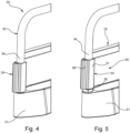
Fig. 1 is a perspective view of two interconnected heavy-duty barriers according to an embodiment of the present invention; -
Fig. 2 is an enlarged view from above of a part of the heavy-duty barrier shown inFig. 1 ; -
Fig. 3 is a perspective view of a connection element, which is part of the heavy-duty barrier shown inFig. 1 ; and -
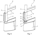
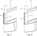
Figs 4 to 12 show further embodiments of the heavy-duty barrier. - An embodiment of the heavy-duty barrier 1 comprises a
base part 2, and afence part 3, which is attached to thebase part 2. Thebase part 2 comprises a steel tub 4 and aconcrete ballast 5, which has been cast into the steel tub 4 to provide the heavy-duty barrier with a level of resistance against overturning, i.e. falling over, when hit by a force, such as caused by a strong wind or by a person falling on thefence part 3. Thebase part 2 is elongated, having a length of for example about 1-3.5 m, or even more, a width of for example about 0.2-0.4 m, and a height of for example 0.2-0.4 m. The total height of the heavy-duty barrier 1 may be about 1-1.2 m. Example weights of the heavy-duty barrier 1 are 200-500 kg. A typical example of the heavy-duty barrier 1 has a length of about 3 m, a width of about 0.3 m, a height of about 1.1 m, and a weight of about 450 kg. As an alternative base part structure, a concrete ballast can be cast in a mold and then used as the base part without the steel tub. - The
fence part 3 comprises a bar structure 6, typically comprising tubular bars, typically with a square or circular cross-section, and twoconnection elements 7, one at each end of the heavy-duty barrier 1. Theconnection elements 7 are rigid. In this embodiment, theconnection elements 7 are similar, and they will additionally be referred to asfirst connection elements 7. In other embodiment the connection elements may be different and will additionally be referred to as first and second connection elements. The bar structure 6 comprises abar portion 8 at each end of the heavy-duty barrier 1, at which theconnection element 7 is movably mounted. For the purposes of this application, in a most simple embodiment asingle connection element 7 is feasible. Thebar portion 8 is a vertical portion, and in the embodiments shown in the drawings it is an end portion of anupper bar 9, which has amajor portion 9a extending horizontally above thebase part 2,end portions base portion 2, andbent portions vertical end portions major portion 9a. Thus, theend portions upper bar 9 provide thebar portions 8 where theconnection elements 7 have been mounted. - Furthermore, the
fence part 3 comprises twolocking elements 10, one at eachconnection element 7. Each lockingelement 10 prevents theconnection element 7 from falling off thebar portion 8 at which it is mounted. In this embodiment, more particularly, the lockingelement 10 extends between the very end of theend portion vertical end post base part 2 at its ends. Thevertical end post adjacent bar portion 8, with which it is connected by means of the lockingelement 10. Additionally, the bar structure 6 comprises amiddle post 12, and alower bar 15. Thelower bar 15 extends horizontally and is located between theupper bar 9 and thebase part 2. More particularly, thelower bar 15 comprises twohalves half 15a extending from themiddle post 12 to oneend portion 9b of theupper bar 9, and theother half 15b extending in the opposite direction, from themiddle post 12 to theother end portion 9c of theupper bar 9. Themiddle post 12 reaches from thebase part 2 up to theupper bar 9. The vertical end posts 11, 13 extend from thebase part 2 up to therespective half lower bar 15. - The
connection element 7 comprises anattachment portion 16, and ahook portion 17. Theattachment portion 16 is tubular and has a slightly larger inner diameter than the outer diameter of thebar portion 8 which theattachment portion 16 encircles. In other words, theattachment portion 16 is concentric with thebar portion 8 and there is a play between the outer surface of thebar portion 8 and the inner surface of theattachment portion 16. Thebar portion 8 has a circular cross-section, and so has theattachment portion 16. Theattachment portion 16 has a longitudinal centre axis C-C, which coincides with a longitudinal centre axis of thebar portion 8. Thus, theconnection element 7 is rotatable about thebar portion 8, and more particularly about the centre axis of thebar portion 8. Additionally, there is room to move theconnection element 7 along the length of thebar portion 8, i.e. vertically. Thehook portion 17 comprises afirst protrusion 18 protruding from theattachment portion 16, and asecond protrusion 19 protruding from the attachment portion. The first andsecond protrusion gap 20 between them, whichgap 20 is arranged to receive a part of afirst protrusion 18 of anotherconnection element 7. The first andsecond protrusions attachment portion 16, and they have a substantial vertical extension, thereby forming opposite first and second walls, respectively. Thefirst protrusion 18 has an L-shaped cross-section, i.e. a cross-section taken perpendicular of the centre axis C-C of theattachment portion 16. The longer portion of the L is attached to theattachment portion 16. A free end of thefirst protrusion 18, i.e. the end of the shorter portion of the L, faces thesecond protrusion 19, and more particularly the surface of thesecond protrusion 19 that faces the gap, which surface can be defined as an inner surface of thesecond protrusion 19. Furthermore, a height of theconnection element 7 is defined as its extension in the direction of the centre axis C-C. The second protrusion, or second wall, 19 is provided with a chute, or bent portion, 21 at the middle of the height of thesecond protrusion 19. The chute 21 extends from theattachment portion 16 to the freed edge of thesecond protrusion 19, and is, for example, V-shaped. The chute strengthens thesecond portion 19, which is generally plate shaped. Thesecond protrusion 19 further comprises anupper edge portion 22 and a lower edge portion 23, which are bent outwards, i.e. away from the opposite portions of thefirst protrusion 18. Thereby, the gap between the first andsecond protrusions connection element 7, which facilitates interconnection of twoconnection elements 7. - When two heavy-duty barriers 1 are to be interconnected, the first heavy-duty barrier is put in place on the ground. Then, the second heavy-duty barrier 1 is lifted and moved close to the first heavy-duty barrier, and the
connection elements 7 of both heavy-duty barriers 1, at their adjacent ends, are aligned with each other. Then, the second heavy-duty barrier is lowered such that itsconnection element 7 is engaged with theconnection element 7 of the adjacent first heavy-duty barrier 1. Thereby the heavy-duty barriers 1 become interconnected as shown inFig. 1 . Another way of interconnecting the heavy-duty barriers 1 is to start with placing the heavy-duty barriers 1 side by side adjacent to each other and in a position that allows retrofitting of theconnection elements 7. This means that theconnection elements 7 and thelocking elements 10 are not mounted on the heavy-duty barriers 1 until after they have been positioned on the ground. How this can be done is understood by the person skilled in the art from the drawings and the above description and will not be elaborated in detail, but, for instance, the lockingelement 10 can be detached to allow mounting of theconnection elements 7 and then reattached. In alternative embodiments, the connection element can be provided with a two-part attachment portion having a demountable semi-cylindrical part. Then the connection element can be mounted also on a bar portion having no accessible free end. - Thus, as shown in
Figs. 1 and2 , when a heavy-duty barrier 1 has been interconnected with a neighbouring heavy-duty barrier 1, thehook portion 17 of theconnection element 7 of the heavy-duty barrier 1 is engaged with thehook portion 17 of acomplementary hook portion 17 of theadjacent connection element 7 of the neighbouring heavy-duty barrier 1. In this embodiment thehook portion 17 and thecomplementary hook portion 17 are identical, and thehook portion 17 is shaped such that the hook portions 17 o twoseparate connection elements 7 are able to move into engagement with each other when turned towards each other. - Due to the rotatability and movability along the
bar portion 8, it is possible to position the heavy-duty barriers 1 at an angle to each other, and a certain ground unevenness is allowed as well. This movability can be slightly enhanced by providing play between theprotrusions interconnected connection elements 7. - According to an embodiment of the heavy-
duty barrier 30, shown inFigs. 4 and 5 , having abase part 31 and afence part 32, the connection element, or first connection element, 33 is movably attached to thebar portion 34 such that theconnection element 33 is rotatable between several rotationally fixed positions. In order to obtain this the heavy-duty barrier 30 further comprises arotation blocking element 36, which has been fixedly arranged, e.g. fixedly attached to thebar portion 34 or to thebase part 31, at a lower end of thebar portion 34. Theconnection element 33 comprises theattachment portion 37 and thehook portion 38. Theattachment portion 37 is tubular with a square cross-section, and therotation blocking element 36 has a square periphery. Thebar portion 34 has a circular cross-section. Inner measures of theattachment portion 37, at least at a lower end thereof, are slightly larger than outer measures of therotation blocking element 36. Thereby, in a fixed position, theattachment portion 37 encloses therotation blocking element 36, which consequently prevents theconnection element 33 from being rotated. To the contrary, in a rotatable position, where theconnection element 33 has been lifted, i.e. has been moved along thebar portion 34, above therotation blocking element 36, theconnection element 33 is freely rotatable about thebar portion 34. In other words, theconnection element 33 is vertically adjustable between a fixed position, where it is rotationally fixed, and a rotatable position. Consequently, theconnection element 33 is settable in four different rotationally fixed positions, with 90 degrees rotation angle between any two adjacent rotationally fixed positions. According to this embodiment, while still allowing adjacent heavy-duty barriers 30 to be arranged either in alignment with each other or at an angle to each other, the strength of the structure of interconnected heavy-duty barriers 30 is higher than a structure of interconnected heavy-duty barriers according to the above-described embodiment. However, this advantage comes with a drawback of losing the possibility of arranging the heavy-duty barriers 30 with an arbitrary angle between two adjacent heavy-duty barriers 30. That is, arbitrary within a large interval only limited by thebase parts 31 of the adjacent heavy-duty barriers 30 hitting each other. - According to an embodiment of the heavy-
duty barrier 40, shown inFigs. 6 and 7 , having abase part 41 and afence part 42, the connection element, or first connection element, 43 is movably attached to thebar portion 44 such that theconnection element 43 is rotatable between several fixed positions. The heavy-duty barrier 40 further comprises arotation blocking element 46, which has been fixedly mounted at a lower end of thebar portion 44. Theconnection element 43 comprises theattachment portion 47 and thehook portion 48. Theattachment portion 47 is tubular and is mounted concentrically of thebar portion 44, and both have circular cross-sections. Furthermore, theconnection element 43 is provided withfirst protrusions 49 and indents 50 at a lower end thereof. Thefirst protrusions 49 and indents are alternatingly and equidistantly arranged along the circumference of theconnection element 43. Therotation blocking element 46 is similarly provided with complementary, or matching,second protrusions 51 and indents 52. Thus, in a rotatably fixed position thefirst protrusions 49 of theconnection element 43 have been received in theindents 52 of therotation blocking element 46, and vice versa, thereby preventing rotation of theconnection element 43. In other words, in the rotatably fixed position thefirst protrusions 49 are engaged with thesecond protrusions 51. Theconnection element 43 is vertically movable to a rotatable position where thefirst protrusions 49 do not extend into theindents 52. Consequently, theconnection element 43 is settable in as many different rotationally fixed positions as there arefirst protrusions 49 at the lower end of theconnection element 43. - According to an embodiment of the heavy-
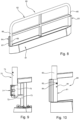
duty barrier 60, shown inFig. 8 , having abase part 61 and afence part 62, the heavy-duty barrier 60 further comprises a rigidfirst connection element 63, and a rigidsecond connection element 64. Thefirst connection element 63 is rotatable about thebar portion 65 at one end of the heavy-duty barrier 60, and thesecond connection element 64 is fixedly attached to thebar portion 66 at the other, opposite, end of the heavy-duty barrier 60. Thefirst connection element 63 can be any of the examples described herein and the like within the scope of the invention. Thesecond connection element 64 comprises ahook portion 67 and anattachment portion 68. Theattachment portion 68 may be merely welding strings or the like attaching thehook portion 67 to thebar portion 65. In this embodiment two neighbouring and interconnected heavy-duty barriers 60 are still pivotable relative to each other to be arranged at either in alignment with each other or at a horizontal angle to each other by connecting thefirst connection element 63 of one heavy-duty barrier 60 with thefirst connection element 63 or thesecond connection element 64 of the other heavy-duty barrier 60. However, by connecting twosecond connection elements 64 with each other the heavy-duty barriers 60 are fixed in horizontal alignment. If this option is undesirable the hook portions of the first andsecond connection elements hook portion 67 of thesecond connection element 64 is only interconnectable with the hook portion of thefirst connection element 63, and vice versa. - In accordance with an embodiment of the heavy-
duty barrier 70, as shown inFig. 9 , the connection element, or first connection element, 71 is rotatable between rotationally fixed positions. Theconnection element 71, and more particularly theattachment portion 75 thereof, is provided withprotrusions 72 at a lower end thereof. In a rotationally fixed position, theprotrusions 72 extend along opposite side surfaces of the lockingelement 73, thereby preventing theconnection element 71 from rotating. Theconnection element 71 is longitudinally movable along thebar portion 74 between the rotationally fixed position and a rotationally non-fixed position. - In accordance with an embodiment of the heavy-
duty barrier 80, as shown inFig. 10 , the connection element, or first connection element, 81 is rotatable between rotationally fixed positions. The heavy-duty barrier 80 comprises arotation blocking element 82 constituting a latch pin. Thebar portion 83, at which theconnection element 81 is rotationally and vertically movably mounted, as well as theconnection element 81 are provided with borings 84 (not shown for the bar portion 83) arranged to receive thelatch pin 82 as a through element, thus simultaneously extending throughopposite borings 84 of theconnection element 81 and aligned opposite borings of thebar portion 83. The borings of the bar portion may be made in, for instance, two orthogonal directions enabling theconnection element 81 to be set in rotationally fixed positions with a rotationally angular spacing of 90 degrees, or at smaller angular distances. To facilitate small angular steps, theconnection element 81 may be provided with two pairs ofopposite borings 84, or more, arranged on top of each other at a vertical distance from each other, and matching pairs of opposite borings may be provided at varying heights of thebar portion 83. - In an embodiment of the heavy-
duty barrier 90, as shown inFigs. 11 and 12 , the heavy-duty barrier 90 comprises afirst connection element 91 mounted at one end of the heavy-duty barrier 90, and asecond connection element 93 mounted at the other, opposite, end of the heavy-duty barrier 90. Like in the above embodiments of the heavy-duty barrier, the first connection element is rotatably and longitudinally, i.e. vertically, movably attached to thebar portion 92. Like in the above embodiment containing a second connection element, thesecond connection element 93 is fixedly attached to thebar portion 94. Furthermore, like in the above embodiments of the heavy-duty barrier the connection elements are rigid. In this embodiment, thehook portions second connection elements hook portion 95 of thefirst connection element 91 is T-shaped in cross-section, and thehook portion 96 of thesecond connection element 93 comprises two elongated portions being L-shaped in cross-section and facing each other defining a space between them, and a slot between the outer edges of the shorter leg of the L-shape. Thus, the shoulder portion of the T-shapedhook portion 95 of thefirst connection element 91 can be received in the space between the L-shaped portions of thehook portion 96 of thesecond connection element 93, with the waist portion of the T-shapedhook portion 95 extending through the slot. - While the invention has been illustrated and described in detail in the drawings and foregoing description, such illustration and description are to be considered illustrative or exemplary and not restrictive. The invention is not limited to the disclosed embodiments.
- For instance, the fence part can be differently designed with fewer or more bars, differently shaped bars, etc., such as a short embodiment where the middle post has been omitted.
- The connection element can be designed, for instance with a fully flat second protrusion, and/or a U-shaped end portion of the first protrusion.
- Other variations to the disclosed embodiments can be understood and effected by those skilled in the art in practicing the claimed invention, from a study of the drawings, the disclosure, and the appended claims. In the claims, the word "comprising" does not exclude other elements or steps, and the indefinite article "a" or "an" does not exclude a plurality. The mere fact that certain measures are recited in mutually different dependent claims does not indicate that a combination of these measured cannot be used to advantage. Any reference signs in the claims should not be construed as limiting the scope.
Claims (14)
- A heavy-duty barrier (1), which is movable, comprising a base part (2), which comprises a ballast (5), and a fence part (3) attached to the base part, wherein the fence part comprises a fixed bar structure (6) and a rigid first connection element (7), which is movably attached to the bar structure, wherein the first connection element comprises an attachment portion (16), movably attached to a bar portion (8) of the bar structure characterized in the attachment portion (16) encircling the circumference of the bar portion, and further characterized in that the connection element comprises a hook portion (17) arranged to be engaged with a complementary hook portion of a rigid connection element of a neighbouring heavy-duty barrier.
- The heavy-duty barrier according to claim 1, wherein the movable attachment of the attachment portion (16) includes rotation of the first connection element (7) about a longitudinal centre axis (C-C) of the bar portion (8).
- The heavy-duty barrier according to claim 1 or 2, wherein the movable attachment of the attachment portion (16) includes movement along a length of the bar portion (8).
- The heavy-duty barrier according to any one of the preceding claims, wherein the attachment portion (16) is tubular.
- The heavy-duty barrier according to any one of the preceding claims, wherein the hook portion (17) comprises a first protrusion (18) protruding from the attachment portion, and a second protrusion (19) protruding from the attachment portion, wherein the first and second protrusions define a gap (20) between them, which gap is arranged to receive a part of a first protrusion of the connection element of a neighbouring heavy-duty barrier.
- The heavy-duty barrier according to claim 5, wherein the first protrusion (18) has an L-shaped cross-section, wherein a free end of the first protrusion (18) faces the second protrusion (19).
- The heavy-duty barrier according to any one of the preceding claims, wherein the base part (2) is made of concrete or is concrete fillable.
- The heavy-duty barrier according to any one of the preceding claims, wherein the first connection element (33, 43, 72, 81) is rotatably movable around the bar portion (34, 44, 74, 83) between several rotatably fixed positions.
- The heavy-duty barrier according to claim 8, wherein the first connection element (33, 43, 72, 81) is arranged to be movable between the fixed positions by means of a combination of longitudinal movement and rotational movement.
- The heavy-duty barrier according to claim 8 or 9, comprising a rotation blocking element (36, 46) fixedly arranged at the bar portion below the first connection element (33, 43), and arranged to engage with the connection element to block rotation thereof.
- The heavy-duty barrier according to claim 10, wherein the attachment portion (47) comprises first protrusions (49) extending downwards, and wherein the rotation blocking element (46) comprises second protrusions (51) extending upwards and engaging with the first protrusions.
- The heavy-duty barrier according to claim 8 or 9, wherein the attachment portion (47, 75) comprises first protrusions (49, 72) extending downwards and arranged to engage with the bar structure (6) to block rotational movement of the connection element.
- The heavy-duty barrier according to any one of claims 1 to 7, wherein the first connection element (7) is freely rotatable to any position.
- The heavy-duty barrier according to any one of the preceding claims, comprising a rigid second connection element (64), wherein the first and second connection elements (63, 64) are arranged at opposite ends of the heavy-duty barrier (60), and wherein the second connection element is fixedly attached to the bar structure and is connectable with at least such a first connection element of a neighbouring heavy-duty barrier.
Applications Claiming Priority (2)
| Application Number | Priority Date | Filing Date | Title |
|---|---|---|---|
| PCT/EP2020/057668 WO2021185450A1 (en) | 2020-03-19 | 2020-03-19 | A heavy-duty barrier |
| PCT/EP2021/057100 WO2021186039A1 (en) | 2020-03-19 | 2021-03-19 | A heavy-duty barrier |
Publications (3)
| Publication Number | Publication Date |
|---|---|
| EP4121601A1 EP4121601A1 (en) | 2023-01-25 |
| EP4121601C0 EP4121601C0 (en) | 2024-07-03 |
| EP4121601B1 true EP4121601B1 (en) | 2024-07-03 |
Family
ID=69953993
Family Applications (2)
| Application Number | Title | Priority Date | Filing Date |
|---|---|---|---|
| EP20713551.8A Active EP4121600B1 (en) | 2020-03-19 | 2020-03-19 | A heavy-duty barrier |
| EP21711929.6A Active EP4121601B1 (en) | 2020-03-19 | 2021-03-19 | A heavy-duty barrier |
Family Applications Before (1)
| Application Number | Title | Priority Date | Filing Date |
|---|---|---|---|
| EP20713551.8A Active EP4121600B1 (en) | 2020-03-19 | 2020-03-19 | A heavy-duty barrier |
Country Status (7)
| Country | Link |
|---|---|
| US (3) | US20230120075A1 (en) |
| EP (2) | EP4121600B1 (en) |
| AU (2) | AU2020436964B2 (en) |
| CA (2) | CA3170591A1 (en) |
| ES (2) | ES2998776T3 (en) |
| PL (2) | PL4121600T3 (en) |
| WO (2) | WO2021185450A1 (en) |
Families Citing this family (8)
| Publication number | Priority date | Publication date | Assignee | Title |
|---|---|---|---|---|
| AU2020436964B2 (en) * | 2020-03-19 | 2024-03-07 | Worxsafe Ab | A heavy-duty barrier |
| USD1056247S1 (en) * | 2022-01-24 | 2024-12-31 | Worxsafe Ab | Protective barrier |
| USD1056248S1 (en) * | 2022-01-24 | 2024-12-31 | Worxsafe Ab | Protective barrier |
| USD1085466S1 (en) * | 2022-01-24 | 2025-07-22 | Worxsafe Ab | Protective barrier |
| USD1085467S1 (en) * | 2022-01-24 | 2025-07-22 | Worxsafe Ab | Protective barrier |
| USD1085465S1 (en) * | 2022-01-24 | 2025-07-22 | Worxsafe Ab | Protective barrier |
| CA214322S (en) * | 2022-03-03 | 2024-10-10 | Worxsafe Ab | Noise barrier module |
| USD1109367S1 (en) * | 2024-03-21 | 2026-01-13 | Worxsafe Ab | Device for accident prevention |
Family Cites Families (24)
| Publication number | Priority date | Publication date | Assignee | Title |
|---|---|---|---|---|
| GB1496651A (en) * | 1974-12-17 | 1977-12-30 | Omk Design Ltd | Connectors |
| US4008575A (en) * | 1975-04-16 | 1977-02-22 | Gallagher John J | Lightweight end connectors for pollution containment boom |
| FR2312602A1 (en) * | 1975-05-29 | 1976-12-24 | Mag | Temporary free standing barrier for crowd control - has inverted T-shaped posts with hooks to mount rectangular panels |
| JPS5832426Y2 (en) * | 1978-06-30 | 1983-07-19 | 古河電気工業株式会社 | fire resistant cable duct |
| US5402988A (en) * | 1989-11-03 | 1995-04-04 | Specialty Recreation Equipment, Inc. | Portable fence |
| FR2756301B1 (en) * | 1996-11-26 | 1998-12-31 | Serravalle Joseph Ets | MOBILE BARRIER AND ASSEMBLY FORMED BY ASSEMBLING A PLURALITY OF SUCH BARRIERS |
| FR2772803A1 (en) * | 1997-12-19 | 1999-06-25 | Rebar | Mobile sectional barrier e.g. for crowd control |
| GB2373806B (en) * | 2001-03-31 | 2005-04-27 | Hill & Smith Ltd | Safety barriers |
| DE10135403A1 (en) * | 2001-07-25 | 2003-02-13 | Hermann Spengler Kg Sand U Bet | Roadway barrier device |
| GB2391560B (en) * | 2002-08-07 | 2005-03-30 | Znd Uk Ltd | Temporary fencing coupler |
| FR2851267B1 (en) * | 2003-02-17 | 2006-01-27 | Plastibeton | DEVICE FOR ASSOCIATING BARRIERS |
| DE10311590A1 (en) * | 2003-03-14 | 2004-09-23 | Hermann Spengler Kg Sand- U. Betonwerk | Concrete crash barrier, has deformable inlay located between adjoining end surfaces of concrete sections |
| US20090032792A1 (en) * | 2005-12-14 | 2009-02-05 | Ryan Lehmann | Arrangement and method for connecting fence sections |
| US20070210293A1 (en) * | 2006-03-13 | 2007-09-13 | Shu-Chen Cheng | Fencing device |
| FR2974124B1 (en) * | 2011-04-15 | 2013-05-31 | Julien Conception | MODULAR SAFETY CURRENT BARRIER WITH QUICK MOUNTING |
| CA2839653A1 (en) * | 2011-06-29 | 2013-01-03 | Wayne Milner | Connection fixture |
| DE202012102366U1 (en) * | 2012-06-27 | 2012-08-06 | Gerald Schake | Device for attaching a beacon to a barrier fence |
| AU2015203840B2 (en) * | 2014-07-11 | 2020-06-18 | Saferoads Pty Ltd | Barrier connection system and connector for use therein |
| AT516032B1 (en) * | 2014-07-23 | 2016-02-15 | Kirchdorfer Fertigteilholding Gmbh | guide wall |
| GB2535732A (en) * | 2015-02-25 | 2016-08-31 | Oxford Plastic Sys Ltd | Barrier connector |
| DE102016006697A1 (en) * | 2016-05-31 | 2017-11-30 | Hermann Spengler Gmbh & Co. Kg | Lane divider |
| AU2020436964B2 (en) * | 2020-03-19 | 2024-03-07 | Worxsafe Ab | A heavy-duty barrier |
| USD1056248S1 (en) * | 2022-01-24 | 2024-12-31 | Worxsafe Ab | Protective barrier |
| USD1056247S1 (en) * | 2022-01-24 | 2024-12-31 | Worxsafe Ab | Protective barrier |
-
2020
- 2020-03-19 AU AU2020436964A patent/AU2020436964B2/en active Active
- 2020-03-19 WO PCT/EP2020/057668 patent/WO2021185450A1/en not_active Ceased
- 2020-03-19 PL PL20713551.8T patent/PL4121600T3/en unknown
- 2020-03-19 EP EP20713551.8A patent/EP4121600B1/en active Active
- 2020-03-19 ES ES20713551T patent/ES2998776T3/en active Active
- 2020-03-19 US US17/911,910 patent/US20230120075A1/en active Pending
- 2020-03-19 CA CA3170591A patent/CA3170591A1/en active Pending
-
2021
- 2021-03-19 US US17/911,911 patent/US12503880B2/en active Active
- 2021-03-19 WO PCT/EP2021/057100 patent/WO2021186039A1/en not_active Ceased
- 2021-03-19 CA CA3170610A patent/CA3170610A1/en active Pending
- 2021-03-19 ES ES21711929T patent/ES2990975T3/en active Active
- 2021-03-19 PL PL21711929.6T patent/PL4121601T3/en unknown
- 2021-03-19 EP EP21711929.6A patent/EP4121601B1/en active Active
- 2021-03-19 AU AU2021236927A patent/AU2021236927B2/en active Active
-
2025
- 2025-12-01 US US19/404,711 patent/US20260085546A1/en active Pending
Also Published As
| Publication number | Publication date |
|---|---|
| EP4121601C0 (en) | 2024-07-03 |
| EP4121600B1 (en) | 2024-11-06 |
| AU2020436964B2 (en) | 2024-03-07 |
| WO2021186039A1 (en) | 2021-09-23 |
| US20230175286A1 (en) | 2023-06-08 |
| PL4121601T3 (en) | 2025-01-07 |
| EP4121600C0 (en) | 2024-11-06 |
| US20260085546A1 (en) | 2026-03-26 |
| EP4121600A1 (en) | 2023-01-25 |
| PL4121600T3 (en) | 2025-03-03 |
| AU2021236927A1 (en) | 2022-10-13 |
| CA3170591A1 (en) | 2021-09-23 |
| AU2020436964A1 (en) | 2022-10-13 |
| US12503880B2 (en) | 2025-12-23 |
| ES2998776T3 (en) | 2025-02-21 |
| AU2021236927B2 (en) | 2024-06-13 |
| WO2021185450A1 (en) | 2021-09-23 |
| CA3170610A1 (en) | 2021-09-23 |
| US20230120075A1 (en) | 2023-04-20 |
| EP4121601A1 (en) | 2023-01-25 |
| ES2990975T3 (en) | 2024-12-02 |
Similar Documents
| Publication | Publication Date | Title |
|---|---|---|
| US20260085546A1 (en) | Heavy-duty barrier | |
| CA1257797A (en) | Security fence | |
| US10006220B2 (en) | Support system and structure supported thereby | |
| US10689819B2 (en) | Brace for erecting a bollard fence | |
| US5544614A (en) | Traffic barricade | |
| US6935464B2 (en) | Extension ladder having an anti-slipping mechanism | |
| US7325787B1 (en) | Barrier | |
| CA2464641A1 (en) | Temporary barrier | |
| GB2524744A (en) | A Framework Structure | |
| AU2018390977B2 (en) | Foundation system and method of construction | |
| WO2019178386A1 (en) | Ring for a fighting sport | |
| US6006861A (en) | Railroad crossing gate ladder assembly | |
| GB2496253A (en) | A system for anchoring fence posts | |
| US12251619B2 (en) | Ring for a fighting sport | |
| CN214786438U (en) | Anti-climbing 5G signal tower | |
| CA2808497C (en) | Base support for hoisting apparatus | |
| CN211057681U (en) | Articulated fence convenient to equipment | |
| KR102938036B1 (en) | A building safety platform | |
| GB2524833A (en) | Safety barrier | |
| GB2591862A (en) | Safety net fan | |
| AU2005202450A1 (en) | Improvements in temporary fencing | |
| AU2007201689A1 (en) | Demountable fences |
Legal Events
| Date | Code | Title | Description |
|---|---|---|---|
| STAA | Information on the status of an ep patent application or granted ep patent |
Free format text: STATUS: UNKNOWN |
|
| STAA | Information on the status of an ep patent application or granted ep patent |
Free format text: STATUS: THE INTERNATIONAL PUBLICATION HAS BEEN MADE |
|
| PUAI | Public reference made under article 153(3) epc to a published international application that has entered the european phase |
Free format text: ORIGINAL CODE: 0009012 |
|
| STAA | Information on the status of an ep patent application or granted ep patent |
Free format text: STATUS: REQUEST FOR EXAMINATION WAS MADE |
|
| 17P | Request for examination filed |
Effective date: 20220927 |
|
| AK | Designated contracting states |
Kind code of ref document: A1 Designated state(s): AL AT BE BG CH CY CZ DE DK EE ES FI FR GB GR HR HU IE IS IT LI LT LU LV MC MK MT NL NO PL PT RO RS SE SI SK SM TR |
|
| DAV | Request for validation of the european patent (deleted) | ||
| DAX | Request for extension of the european patent (deleted) | ||
| GRAP | Despatch of communication of intention to grant a patent |
Free format text: ORIGINAL CODE: EPIDOSNIGR1 |
|
| STAA | Information on the status of an ep patent application or granted ep patent |
Free format text: STATUS: GRANT OF PATENT IS INTENDED |
|
| INTG | Intention to grant announced |
Effective date: 20230920 |
|
| GRAJ | Information related to disapproval of communication of intention to grant by the applicant or resumption of examination proceedings by the epo deleted |
Free format text: ORIGINAL CODE: EPIDOSDIGR1 |
|
| STAA | Information on the status of an ep patent application or granted ep patent |
Free format text: STATUS: REQUEST FOR EXAMINATION WAS MADE |
|
| GRAP | Despatch of communication of intention to grant a patent |
Free format text: ORIGINAL CODE: EPIDOSNIGR1 |
|
| STAA | Information on the status of an ep patent application or granted ep patent |
Free format text: STATUS: GRANT OF PATENT IS INTENDED |
|
| INTC | Intention to grant announced (deleted) | ||
| INTG | Intention to grant announced |
Effective date: 20240220 |
|
| GRAS | Grant fee paid |
Free format text: ORIGINAL CODE: EPIDOSNIGR3 |
|
| GRAA | (expected) grant |
Free format text: ORIGINAL CODE: 0009210 |
|
| STAA | Information on the status of an ep patent application or granted ep patent |
Free format text: STATUS: THE PATENT HAS BEEN GRANTED |
|
| AK | Designated contracting states |
Kind code of ref document: B1 Designated state(s): AL AT BE BG CH CY CZ DE DK EE ES FI FR GB GR HR HU IE IS IT LI LT LU LV MC MK MT NL NO PL PT RO RS SE SI SK SM TR |
|
| REG | Reference to a national code |
Ref country code: CH Ref legal event code: EP |
|
| REG | Reference to a national code |
Ref country code: DE Ref legal event code: R096 Ref document number: 602021015140 Country of ref document: DE |
|
| U01 | Request for unitary effect filed |
Effective date: 20240708 |
|
| U07 | Unitary effect registered |
Designated state(s): AT BE BG DE DK EE FI FR IT LT LU LV MT NL PT SE SI Effective date: 20240718 |
|
| REG | Reference to a national code |
Ref country code: SK Ref legal event code: T3 Ref document number: E 44696 Country of ref document: SK |
|
| REG | Reference to a national code |
Ref country code: ES Ref legal event code: FG2A Ref document number: 2990975 Country of ref document: ES Kind code of ref document: T3 Effective date: 20241202 |
|
| PG25 | Lapsed in a contracting state [announced via postgrant information from national office to epo] |
Ref country code: GR Free format text: LAPSE BECAUSE OF FAILURE TO SUBMIT A TRANSLATION OF THE DESCRIPTION OR TO PAY THE FEE WITHIN THE PRESCRIBED TIME-LIMIT Effective date: 20241004 |
|
| PG25 | Lapsed in a contracting state [announced via postgrant information from national office to epo] |
Ref country code: IS Free format text: LAPSE BECAUSE OF FAILURE TO SUBMIT A TRANSLATION OF THE DESCRIPTION OR TO PAY THE FEE WITHIN THE PRESCRIBED TIME-LIMIT Effective date: 20241103 |
|
| PG25 | Lapsed in a contracting state [announced via postgrant information from national office to epo] |
Ref country code: HR Free format text: LAPSE BECAUSE OF FAILURE TO SUBMIT A TRANSLATION OF THE DESCRIPTION OR TO PAY THE FEE WITHIN THE PRESCRIBED TIME-LIMIT Effective date: 20240703 |
|
| PG25 | Lapsed in a contracting state [announced via postgrant information from national office to epo] |
Ref country code: RS Free format text: LAPSE BECAUSE OF FAILURE TO SUBMIT A TRANSLATION OF THE DESCRIPTION OR TO PAY THE FEE WITHIN THE PRESCRIBED TIME-LIMIT Effective date: 20241003 |
|
| PG25 | Lapsed in a contracting state [announced via postgrant information from national office to epo] |
Ref country code: RS Free format text: LAPSE BECAUSE OF FAILURE TO SUBMIT A TRANSLATION OF THE DESCRIPTION OR TO PAY THE FEE WITHIN THE PRESCRIBED TIME-LIMIT Effective date: 20241003 Ref country code: IS Free format text: LAPSE BECAUSE OF FAILURE TO SUBMIT A TRANSLATION OF THE DESCRIPTION OR TO PAY THE FEE WITHIN THE PRESCRIBED TIME-LIMIT Effective date: 20241103 Ref country code: HR Free format text: LAPSE BECAUSE OF FAILURE TO SUBMIT A TRANSLATION OF THE DESCRIPTION OR TO PAY THE FEE WITHIN THE PRESCRIBED TIME-LIMIT Effective date: 20240703 Ref country code: GR Free format text: LAPSE BECAUSE OF FAILURE TO SUBMIT A TRANSLATION OF THE DESCRIPTION OR TO PAY THE FEE WITHIN THE PRESCRIBED TIME-LIMIT Effective date: 20241004 |
|
| U20 | Renewal fee for the european patent with unitary effect paid |
Year of fee payment: 5 Effective date: 20250224 |
|
| PG25 | Lapsed in a contracting state [announced via postgrant information from national office to epo] |
Ref country code: SM Free format text: LAPSE BECAUSE OF FAILURE TO SUBMIT A TRANSLATION OF THE DESCRIPTION OR TO PAY THE FEE WITHIN THE PRESCRIBED TIME-LIMIT Effective date: 20240703 |
|
| PLBE | No opposition filed within time limit |
Free format text: ORIGINAL CODE: 0009261 |
|
| STAA | Information on the status of an ep patent application or granted ep patent |
Free format text: STATUS: NO OPPOSITION FILED WITHIN TIME LIMIT |
|
| 26N | No opposition filed |
Effective date: 20250404 |
|
| PGFP | Annual fee paid to national office [announced via postgrant information from national office to epo] |
Ref country code: ES Payment date: 20250402 Year of fee payment: 5 |
|
| PGFP | Annual fee paid to national office [announced via postgrant information from national office to epo] |
Ref country code: CH Payment date: 20250401 Year of fee payment: 5 |
|
| PG25 | Lapsed in a contracting state [announced via postgrant information from national office to epo] |
Ref country code: MC Free format text: LAPSE BECAUSE OF FAILURE TO SUBMIT A TRANSLATION OF THE DESCRIPTION OR TO PAY THE FEE WITHIN THE PRESCRIBED TIME-LIMIT Effective date: 20240703 |
|
| REG | Reference to a national code |
Ref country code: CH Ref legal event code: U11 Free format text: ST27 STATUS EVENT CODE: U-0-0-U10-U11 (AS PROVIDED BY THE NATIONAL OFFICE) Effective date: 20260401 |
|
| PGFP | Annual fee paid to national office [announced via postgrant information from national office to epo] |
Ref country code: GB Payment date: 20260318 Year of fee payment: 6 |
|
| PGFP | Annual fee paid to national office [announced via postgrant information from national office to epo] |
Ref country code: NO Payment date: 20260318 Year of fee payment: 6 Ref country code: IE Payment date: 20260317 Year of fee payment: 6 |
|
| PG25 | Lapsed in a contracting state [announced via postgrant information from national office to epo] |
Ref country code: RO Free format text: LAPSE BECAUSE OF FAILURE TO SUBMIT A TRANSLATION OF THE DESCRIPTION OR TO PAY THE FEE WITHIN THE PRESCRIBED TIME-LIMIT Effective date: 20240703 |
|
| PGFP | Annual fee paid to national office [announced via postgrant information from national office to epo] |
Ref country code: TR Payment date: 20260312 Year of fee payment: 6 |
|
| U20 | Renewal fee for the european patent with unitary effect paid |
Year of fee payment: 6 Effective date: 20260318 |
|
| PGFP | Annual fee paid to national office [announced via postgrant information from national office to epo] |
Ref country code: CZ Payment date: 20260317 Year of fee payment: 6 |
|
| PGFP | Annual fee paid to national office [announced via postgrant information from national office to epo] |
Ref country code: PL Payment date: 20260216 Year of fee payment: 6 |
|
| PGFP | Annual fee paid to national office [announced via postgrant information from national office to epo] |
Ref country code: SK Payment date: 20260310 Year of fee payment: 6 |