EP4121240B1 - Generative pulverbettfusionsfertigung mit lastausgleich für mehrere strahlen - Google Patents
Generative pulverbettfusionsfertigung mit lastausgleich für mehrere strahlen Download PDFInfo
- Publication number
- EP4121240B1 EP4121240B1 EP22723049.7A EP22723049A EP4121240B1 EP 4121240 B1 EP4121240 B1 EP 4121240B1 EP 22723049 A EP22723049 A EP 22723049A EP 4121240 B1 EP4121240 B1 EP 4121240B1
- Authority
- EP
- European Patent Office
- Prior art keywords
- fusing
- area
- beam source
- locations
- opt
- Prior art date
- Legal status (The legal status is an assumption and is not a legal conclusion. Google has not performed a legal analysis and makes no representation as to the accuracy of the status listed.)
- Active
Links
Images




Classifications
-
- B—PERFORMING OPERATIONS; TRANSPORTING
- B22—CASTING; POWDER METALLURGY
- B22F—WORKING METALLIC POWDER; MANUFACTURE OF ARTICLES FROM METALLIC POWDER; MAKING METALLIC POWDER; APPARATUS OR DEVICES SPECIALLY ADAPTED FOR METALLIC POWDER
- B22F10/00—Additive manufacturing of workpieces or articles from metallic powder
- B22F10/80—Data acquisition or data processing
- B22F10/85—Data acquisition or data processing for controlling or regulating additive manufacturing processes
-
- B—PERFORMING OPERATIONS; TRANSPORTING
- B22—CASTING; POWDER METALLURGY
- B22F—WORKING METALLIC POWDER; MANUFACTURE OF ARTICLES FROM METALLIC POWDER; MAKING METALLIC POWDER; APPARATUS OR DEVICES SPECIALLY ADAPTED FOR METALLIC POWDER
- B22F12/00—Apparatus or devices specially adapted for additive manufacturing; Auxiliary means for additive manufacturing; Combinations of additive manufacturing apparatus or devices with other processing apparatus or devices
- B22F12/40—Radiation means
- B22F12/44—Radiation means characterised by the configuration of the radiation means
- B22F12/45—Two or more
-
- B—PERFORMING OPERATIONS; TRANSPORTING
- B22—CASTING; POWDER METALLURGY
- B22F—WORKING METALLIC POWDER; MANUFACTURE OF ARTICLES FROM METALLIC POWDER; MAKING METALLIC POWDER; APPARATUS OR DEVICES SPECIALLY ADAPTED FOR METALLIC POWDER
- B22F10/00—Additive manufacturing of workpieces or articles from metallic powder
- B22F10/20—Direct sintering or melting
- B22F10/28—Powder bed fusion, e.g. selective laser melting [SLM] or electron beam melting [EBM]
-
- B—PERFORMING OPERATIONS; TRANSPORTING
- B22—CASTING; POWDER METALLURGY
- B22F—WORKING METALLIC POWDER; MANUFACTURE OF ARTICLES FROM METALLIC POWDER; MAKING METALLIC POWDER; APPARATUS OR DEVICES SPECIALLY ADAPTED FOR METALLIC POWDER
- B22F10/00—Additive manufacturing of workpieces or articles from metallic powder
- B22F10/30—Process control
- B22F10/36—Process control of energy beam parameters
- B22F10/366—Scanning parameters, e.g. hatch distance or scanning strategy
-
- B—PERFORMING OPERATIONS; TRANSPORTING
- B29—WORKING OF PLASTICS; WORKING OF SUBSTANCES IN A PLASTIC STATE IN GENERAL
- B29C—SHAPING OR JOINING OF PLASTICS; SHAPING OF MATERIAL IN A PLASTIC STATE, NOT OTHERWISE PROVIDED FOR; AFTER-TREATMENT OF THE SHAPED PRODUCTS, e.g. REPAIRING
- B29C64/00—Additive manufacturing, i.e. manufacturing of three-dimensional [3D] objects by additive deposition, additive agglomeration or additive layering, e.g. by 3D printing, stereolithography or selective laser sintering
- B29C64/10—Processes of additive manufacturing
- B29C64/141—Processes of additive manufacturing using only solid materials
- B29C64/153—Processes of additive manufacturing using only solid materials using layers of powder being selectively joined, e.g. by selective laser sintering or melting
-
- B—PERFORMING OPERATIONS; TRANSPORTING
- B29—WORKING OF PLASTICS; WORKING OF SUBSTANCES IN A PLASTIC STATE IN GENERAL
- B29C—SHAPING OR JOINING OF PLASTICS; SHAPING OF MATERIAL IN A PLASTIC STATE, NOT OTHERWISE PROVIDED FOR; AFTER-TREATMENT OF THE SHAPED PRODUCTS, e.g. REPAIRING
- B29C64/00—Additive manufacturing, i.e. manufacturing of three-dimensional [3D] objects by additive deposition, additive agglomeration or additive layering, e.g. by 3D printing, stereolithography or selective laser sintering
- B29C64/20—Apparatus for additive manufacturing; Details thereof or accessories therefor
- B29C64/264—Arrangements for irradiation
- B29C64/277—Arrangements for irradiation using multiple radiation means, e.g. micromirrors or multiple light-emitting diodes [LED]
- B29C64/282—Arrangements for irradiation using multiple radiation means, e.g. micromirrors or multiple light-emitting diodes [LED] of the same type, e.g. using different energy levels
-
- B—PERFORMING OPERATIONS; TRANSPORTING
- B29—WORKING OF PLASTICS; WORKING OF SUBSTANCES IN A PLASTIC STATE IN GENERAL
- B29C—SHAPING OR JOINING OF PLASTICS; SHAPING OF MATERIAL IN A PLASTIC STATE, NOT OTHERWISE PROVIDED FOR; AFTER-TREATMENT OF THE SHAPED PRODUCTS, e.g. REPAIRING
- B29C64/00—Additive manufacturing, i.e. manufacturing of three-dimensional [3D] objects by additive deposition, additive agglomeration or additive layering, e.g. by 3D printing, stereolithography or selective laser sintering
- B29C64/30—Auxiliary operations or equipment
- B29C64/364—Conditioning of environment
- B29C64/371—Conditioning of environment using an environment other than air, e.g. inert gas
-
- B—PERFORMING OPERATIONS; TRANSPORTING
- B29—WORKING OF PLASTICS; WORKING OF SUBSTANCES IN A PLASTIC STATE IN GENERAL
- B29C—SHAPING OR JOINING OF PLASTICS; SHAPING OF MATERIAL IN A PLASTIC STATE, NOT OTHERWISE PROVIDED FOR; AFTER-TREATMENT OF THE SHAPED PRODUCTS, e.g. REPAIRING
- B29C64/00—Additive manufacturing, i.e. manufacturing of three-dimensional [3D] objects by additive deposition, additive agglomeration or additive layering, e.g. by 3D printing, stereolithography or selective laser sintering
- B29C64/30—Auxiliary operations or equipment
- B29C64/386—Data acquisition or data processing for additive manufacturing
- B29C64/393—Data acquisition or data processing for additive manufacturing for controlling or regulating additive manufacturing processes
-
- B—PERFORMING OPERATIONS; TRANSPORTING
- B33—ADDITIVE MANUFACTURING TECHNOLOGY
- B33Y—ADDITIVE MANUFACTURING, i.e. MANUFACTURING OF THREE-DIMENSIONAL [3D] OBJECTS BY ADDITIVE DEPOSITION, ADDITIVE AGGLOMERATION OR ADDITIVE LAYERING, e.g. BY 3D PRINTING, STEREOLITHOGRAPHY OR SELECTIVE LASER SINTERING
- B33Y50/00—Data acquisition or data processing for additive manufacturing
- B33Y50/02—Data acquisition or data processing for additive manufacturing for controlling or regulating additive manufacturing processes
-
- B—PERFORMING OPERATIONS; TRANSPORTING
- B22—CASTING; POWDER METALLURGY
- B22F—WORKING METALLIC POWDER; MANUFACTURE OF ARTICLES FROM METALLIC POWDER; MAKING METALLIC POWDER; APPARATUS OR DEVICES SPECIALLY ADAPTED FOR METALLIC POWDER
- B22F2999/00—Aspects linked to processes or compositions used in powder metallurgy
-
- B—PERFORMING OPERATIONS; TRANSPORTING
- B33—ADDITIVE MANUFACTURING TECHNOLOGY
- B33Y—ADDITIVE MANUFACTURING, i.e. MANUFACTURING OF THREE-DIMENSIONAL [3D] OBJECTS BY ADDITIVE DEPOSITION, ADDITIVE AGGLOMERATION OR ADDITIVE LAYERING, e.g. BY 3D PRINTING, STEREOLITHOGRAPHY OR SELECTIVE LASER SINTERING
- B33Y10/00—Processes of additive manufacturing
-
- B—PERFORMING OPERATIONS; TRANSPORTING
- B33—ADDITIVE MANUFACTURING TECHNOLOGY
- B33Y—ADDITIVE MANUFACTURING, i.e. MANUFACTURING OF THREE-DIMENSIONAL [3D] OBJECTS BY ADDITIVE DEPOSITION, ADDITIVE AGGLOMERATION OR ADDITIVE LAYERING, e.g. BY 3D PRINTING, STEREOLITHOGRAPHY OR SELECTIVE LASER SINTERING
- B33Y30/00—Apparatus for additive manufacturing; Details thereof or accessories therefor
-
- Y—GENERAL TAGGING OF NEW TECHNOLOGICAL DEVELOPMENTS; GENERAL TAGGING OF CROSS-SECTIONAL TECHNOLOGIES SPANNING OVER SEVERAL SECTIONS OF THE IPC; TECHNICAL SUBJECTS COVERED BY FORMER USPC CROSS-REFERENCE ART COLLECTIONS [XRACs] AND DIGESTS
- Y02—TECHNOLOGIES OR APPLICATIONS FOR MITIGATION OR ADAPTATION AGAINST CLIMATE CHANGE
- Y02P—CLIMATE CHANGE MITIGATION TECHNOLOGIES IN THE PRODUCTION OR PROCESSING OF GOODS
- Y02P10/00—Technologies related to metal processing
- Y02P10/25—Process efficiency
Definitions
- the invention relates to a method and an apparatus for the powder bed fusion process and to a storage medium comprising instructions to execute the method.
- the powder bed fusion process consists of iteratively applying a powder layer onto a support structure and selectively adhering powder particles to another or previously adhered agglomerates by heating the respective particles using an electron beam, a laser beam or any other kind of radiation beam (hereinafter jointly "beam" for short).
- Adhering particles of a powder bed by scanning a surface of the powder bed with a beam is referred to as fusing, regardless of the physical or chemical process (melting, sintering, welding, radiation induced chemical reaction, ...) that provides the result of adhered particles.
- sectional views of the product to be manufactured are so to speak written on each newly applied top layer by moving a beam spot over the surface of the upmost powder layer.
- a so-called powder bed is formed. Embedded in the powder bed is the already manufactured portion of the workpiece.
- additional auxiliary structures have to be "written” into the powder layer, but herein we do not focus on this aspect and we consider these to be a part of the workpiece.
- the workpiece potentially with its adhering auxiliary structures, may be removed from the powder bed and may be subjected to further processing, if required.
- product and workpiece are used interchangeably in this field and hence herein.
- the powder bed fusion process is very capable, but it is desirable to reduce the manufacturing times for a given workpiece.
- multiple beams sourced can be distributed at different locations above the powder bed to reduce imperfections due to beam expansion and parallaxes.
- This approach has limitations, for example fumes being produced by a first beam may interfere with another beam, which is detrimental to the quality of the product.
- Other problems are related to heat dissipation in the powder bed or to beam spot distortion. Beam spot distortion describes the effect of an increasing elliptic distortion of the beam spot formed on the powder bed as a function of increasing deviation of the angle of incidence from a near normal incidence.
- WO 2016/075026 A suggests optimizing a multi beam laser powder bed fusion process by virtually separating the surface of a powder bed into a number of surfaces sections, wherein each beam illuminates and hence fuses powder particles in a single surface section being assigned to said beam.
- the areas of the actually illuminated surfaces may be compared and based on the comparison the boundaries between the surface sections may be adjusted to compensate for differences in the actually illuminated surfaces.
- WO 2020/178216 A suggests controlling the positions of the beam spots of a multi beam laser powder bed fusion process such that at - no point in time - any line connecting two beam spots is parallel to a flow direction of an inert gas flow over the powder bed.
- DE 10 2013 205 724 A1 suggests improving the powder bed process by coordinating the direction in which the beam of a beam source scans a portion of the powder bed and the inert gas flow direction. This coordination can be obtained by limiting the angle of the scanning direction and the inert gas flow direction to the interval [22.5°, 337.5°], preferably to the interval [90° and 270°].
- W0 2016/110 440 A1 as well relates to a multiple beam powder bed process.
- Each beam has a field of view and at least two of these fields of view are overlapping.
- the sectional view is scanned by the beams at the same time, wherein the distance between the spots being irradiated at the same time is reduced over time until the irradiated spots of the beams at least partially, preferably fully overlap.
- the beam intensities are reduced with an increase of the overlap to maintain the energy being provided to each spot of the sectional view being scanned constant.
- US 2016/0114432 A1 discloses a laser selective solidification apparatus and method, where the utilisation of a plurality of laser beams is balanced.
- the object of the invention is thus to further improve the multi beam powder bed fusion process with the object of reducing the cost for manufacturing a workpiece.
- the invention is based on the observation that the prior art suggestions for defining the boundary between two adjacent surface sections of the surface of a top layer of a powder bed is based on the beam-on times measured when writing the previous layer. This process iteratively finds the optimum boundary position and hence leads to a significant cumulation of idle times. This approach is further increasingly inefficient, the more the surface areas to be illuminated in the different surface sections change from layer to layer.
- the method for manufacturing a workpiece comprises fusing an area A ("the area A ", for short) of a surface of a layer of a fusible material ("the layer ", for short).
- the layer may be the present upmost layer of a powder bed on top of a powder bed support of an additive manufacturing machine configured to use and/or to implement the powder bed fusion process.
- the next layer may be applied to the powder bed, e.g. using a recoater.
- the upmost layer may be the first layer of the powder bed being subsequently deposited during the process.
- the symbol A thus represents a set of locations (points) that can be represented as vectors p , all in the plane defined by the surface of the layer, which shall be and during the process are irradiated by at least one beam spot being emitted by a beam source.
- hence symbolizes a value indicative for the size of the surface of the aera A, i.e.
- is the surface area of the area A.
- is a norm, generally referred to as
- the area A may be the entire area EA of the layer to be irradiated, but in another example, the area A may be only a portion thereof, i.e. A ⁇ EA.
- those parts of the entire area EA to be irradiated that define, e.g., a portion of the contour of the workpiece may be subtracted from the entire area to thereby obtain "the area A ".
- the contour portions being subtracted may, for example, be irradiated always by the same beam source to increase the quality of the workpiece surface defined by said contour.
- the 'entire area' EA may be divided in subareas, e.g. to improve fume management.
- the area A may be a subarea of the 'entire area EA ' .
- the area A may be at least a portion of a sectional view of the workpiece to be manufactured by application of the laser powder bed fusion process, wherein the section plane corresponds to the position of the layer of fusible material to be irradiated.
- the area A may comprise multiple subareas, we call sectors to distinguish the sectors verbally from the previously discussed 'subareas of the entire area to be irradiated'.
- the sectors may by spaced from each other, i.e. there may be a gap between neighboured sectors of the area A.
- the area A can be irradiated by beams being emitted by the beam sources.
- the symbol A l may be used.
- a 1 would be an area on the first layer of a powder bed
- a 2 an area of subsequent layer of the powder bed
- a l is an area on the l th -layer. If the up script is omitted this means that the position of the Area A in the sequence of layers is not relevant and may take any number.
- the area A is typically determined by a so called "slicer” based on a CAD-model of the workpiece to be manufactured. But the invention is not limited to this example.
- the method comprises fusing the portion of the fusible material of the layer as defined by the surface area A .
- at least two spots of at least two beams are projected by at least two beam sources onto the set of locations defining the surface area A.
- the method can be used in case there are only two beam sources, but practice the number is higher. Typical values are, depending on the size of the layer, between 8 to 12, but the invention is not limited to this range. Future powder bed fusing apparatuses are expected to have even higher numbers of beam sources. Herein we symbolize the total number of beam sources being available by " n ".
- This number " n " of beam sources being available may be different from the number of beam sources of the powder bed fusion apparatus. For example, if one or more beam sources has or have been assigned the task of fusing a contour portion which is not a portion of the area A, then these assigned beam source(s) cannot contribute to fusing the area A, while fusing the respective contour portion(s). Once the assigned contour portions have been fused, these beam sources can be used to fuse sections of the area and the number "n", hence can be increased. Another ground for a number "n” being smaller than the number of installed beam sources may be to reduce the thermal power that needs to be removed from the workpiece or simply because a section of the area would be so small that location management would be difficult.
- the number "n" represents the number of lasers being assigned to jointly fuse an area A.
- the number may even change during the process of assigning locations of the area A to the sets of locations L i (1 ⁇ i ⁇ n ) which may then be fused by the corresponding i ⁇ th -beam source. This may, e.g., happen if it turns out that the size of the area of a set of locations L i would be below a predefined threshold T i .
- Each of the n , ( n ⁇ 2) beam sources has a predefined field of view F i , wherein the index i indicates the corresponding i th -beam source, e.g. F 1 is the field of view of the first beam source, F 2 is the field of view of the second beam source, or more generally F i is the field of view of the i th -beam source.
- the field of view F i is the surface portion of the layer that can be irradiated by the corresponding i th -beam being emitted by the i th -beam source.
- each field of view F i may be defined by a scanner optic of the i th -beam source.
- Constraints in the field of view F i may be imposed by pivot ranges of a scanner optic, limits of (optional) focussing optics and as well by a limit of the acceptable beam distortion.
- the field of view F i can be understood as the portion of the layer that can be reasonably fused using the corresponding i th -beam source.
- the field of view F i can thus be expressed as set of vectors f i on the surface of the layer that can be irradiated and hence fused using the i th -beam source.
- is the size of the portion of the surface of the layer that can be irradiated by the corresponding i th -beam source.
- each beam source i has a predefined fuse rate R i (a positive real number), wherein the fuse rate indicates the size of the surface field of view that can be fused by the i th -beam source per unit of time.
- the fuse rate R i is a surface area per time and hence can be measured, e.g. in m 2 s meter 2 second or the like. For example, when fusing a surface, the beam spot often travels along a first vector, defining a first fuse trace until a stop condition is reached. Then the beam may be switched off and the beam source is repositioned to a new start point. Next, the beam is switched on again and the beam spot travel may travel, e.g. parallel to the previously fused fuse trace.
- the fuse rate R i may thus account for the time being required to reposition the beam source.
- the fuse rate R i can be considered as a mean fuse rate that may be determined iteratively with an increasing accuracy.
- the fuse rates R i may differ between different beam sources and may as well depend on a given material to be fused.
- the fuse rate R i is simply the length (times the width) of a trace the i th -laser scans per unit of time without accounting for the time required to reposition laser beam optics when starting a new trace.
- each location p of the area A is fused only by a single beam source.
- the different sets of locations L i may be irradiated at the same time.
- the trajectories of the projections of the beam spots of different beams sources may overlap, e.g. similar to the overlapping of sections of a single beam's trajectory to ensure a given strength and surface quality in those regions of the layer, where the final workpiece shall not have a gap.
- n indicates the number of beam sources having a field of view with an overlap with the area A being greater than a threshold T , i.e. only those beam sources are considered for which
- an optimum fusing time t o ( i ) can be determined by dividing the size of the area
- all beam sources would require the same amount of time to fuse their respective sets of locations L i , i.e. idle times are minimized.
- Other estimations may be used as well.
- the optimum fusing time depends on the size of the surface area
- Further intersecting sets IS i may be determined as well, wherein IS i is the intersecting set being associated to the i th -beam source.
- is compared to the product of the optimum fusing time t o ( i ) with the fuse rate R i of the corresponding i th -beam source (step 1.3) and if the relation t o (i) ⁇ R i ⁇
- the step may be generalized to obtain the i th -subtrahend surface S i being associated to the i th -beam source, i.e. generalizing in case the condition t o ( i ) ⁇ R i ⁇
- the method can be repeated for each layer and hence the time for manufacturing a workpiece is minimized.
- the cost for manufacturing the workpiece is reduced.
- t tot Max ( t o ( i )) and identical to the lower limit being inherent to the apparatus and the material to be fused.
- step 1.4 preferably at least the steps 1.2 to 1.3.2 are repeated for each other beam source, i.e. for all remaining beam sources (1 ⁇ i ⁇ n).
- Step 1.4 is preferably executed for at least two different L i , L j , ( i ⁇ j ) at the same time. The higher the number of beams that are irradiating their correspondingly assigned surfaces L i simultaneously the better.
- all n beam sources irradiate at the same time.
- a subtrahend surface S i is defined with S i ⁇ IS i under the condition that for each p i ⁇ S i , ⁇ F k
- steps 1.3.1 and 1.3.2 may be executed while the condition (1 - ⁇ i ) ⁇ (
- the corrected minimum time may then be used in future executions of steps 1.3 to 1.3.2 and instead of an initially calculated or estimated optimum fusing time.
- This adjustment of the optimum time t o ( i ) enhances an even load distribution between the beam sources for which the set of locations has not yet been determined, i.e. the variation of
- ⁇ t ( i ) 0 and i indicates the i th - execution of the steps.
- ⁇ t,i as defined above serves as an error margin and t o ( i ) is selected to be within boundaries being given by selection either the "+” or the "-" of " ⁇ ".
- ⁇ t ,1 ⁇ t ( i ) can be different for every iteration only for simplicity we will write ⁇ t as well.
- the of step calculating a corrected minimum time is particularly useful if the effects of non-negligible ⁇ i sum up.
- the threshold T i may be defined for each i th -beam source individually. It may as well be set manually for each beam source individually or for all or a number of beam sources, e.g. based on the experience of an operator.
- the method further comprises to define at least a first (preferably meandering) line B i,j and preferably as well a second (preferably meandering) line B i,k , wherein the first (preferably meandering) line B i,j extends (preferably meanders) in a first direction b 1 and the second (preferably meandering) line B i,k extends (preferably meanders) in a second direction b 2 (step 4.1).
- the first (preferably meandering) line may be used to limit the extension the subtrahend surface S i in a direction being at least essentially orthogonal to the first direction b 1 .
- the second (preferably meandering) line may be used to limit the extension the subtrahend surface S i in a direction being at least essentially orthogonal to the second direction b 2 .
- At least one of the first and second (preferably meandering) lines hence determines a first boundary of the subtrahend surface S i (step 4.2).
- B j,i B i,j .
- the first (preferably meandering) line B i,j is preferably shifted at least essentially orthogonal to the first direction b 1 and/or the second (preferably meandering) line is preferably shifted at least essentially orthogonal to the second direction b 2 to reduce ⁇ S i , preferably until the condition 1.3.1 is met.
- the two vectors b 1 , b 2 are preferably linearly independent (condition 5), and particularly preferred they are at least essentially orthogonal to each other, i.e. preferably b 1 ⁇ b 2 . Exceptionally the indices of the vectors b 1 , b 2 , ... are not associated with a beam source, these serve only to distinguish these vectors.
- the indices of the lines B i , j however are associated to two beam sources, namely to the i th - and to the j th -beam source, after determining all L i , the (preferably meandering) line B i , j separates the sets of locations L i and L j .
- a line B i , j meanders along or in the direction b 1 if the line B i,j has a first end point b i,j,e that obeys the condition
- Fusing the fusible material at the set of locations L i may comprise pivoting the i th -beam source while the i th -beam source projects an i th -beam spot to thereby move the i th -beam spot along lines being multiples of a vector v i .
- the meandering lines comprise or consist of concatenated sections being, in alternating sequence, perpendicular to v i or parallel to v i (step 6).
- the method further comprises to execute the steps 1.2 and 1.3 (and optionally of course as well all other steps) first for the beam source that has a field of view which has the least overlap with the fields of view of other beam sources.
- the steps are executed for the beam source which field of view has the second least overlap with other fields of view and so. This helps to reduce the computational effort when calculating the corresponding subtrahend surfaces S i , as in this way first those portions of the area are assigned to a set of locations L i that in the worst case can be irradiated only by a single beam source, which may -if not accounted for- yield to the situation that a single beam source operates much longer than the others.
- this means that preferably initially, but at latest prior to step 1.2 the indices of the fields of view F i are preferably sorted to obey the condition Min ⁇ j i ⁇ j F i ⁇ F j ⁇ Min ⁇ j i + 1 ⁇ j F i + 1 ⁇ F j ⁇ i ⁇ n and that at least the steps 1.2 and 1.3 are repeated while increasing the value of the index with each repetition by one until the index i n .
- the method may comprise (as well prior to step 1.2), sorting the indices of the fields of view F i to obey the condition
- this sorting step eases determining the subtrahend surfaces S i , while maintaining the error margin ⁇ i small, i.e. to reduce avoidable idle times of beam sources that generally could contribute to fusing the area A.
- the method may further comprise, prior to determining a subtrahend surface S i to assigning a portion C i of the area A to a dedicated i th -beam source.
- the beam sources are calibrated to operate all in the same coordinate system. This calibration, however, is not perfect and can deteriorate during the process of manufacturing.
- imperfections of the workpiece can be reduced in this portion C i , thus C i ⁇ F i , i.e. the portion C i is within the field of view F i .
- such an assignment increases the total manufacturing time, because the load distribution between the different beam-sources is deteriorated.
- This step provides a number of advantages: The memory requirements are reduced and further determining a suited subtrahend surface S i is significantly simplified, leading to further cost optimizations. The idea underlying this improvement is that those portions of the field of view F i that already have been assigned to sets of locations L i , (i ⁇ j) in previous executions i of at least one of the steps 1.2 to 1.3.2 and/or 1.2 to 2.3 do not need to be included in further considerations.
- a flow in a flow direction parallel to the top surface of the layer is established, e.g. by arranging at least one inlet nozzle at a first side of the top layer and at least one outlet nozzle at the opposite side of the top layer and by establishing an inert gas flow from the inlet nozzle to the outlet nozzle, thereby defining a main flow direction.
- the method may further comprise establishing an inert gas flow in a flow direction d over the top of the powder bed, wherein d h denotes the (preferably normalized) component of the flow direction being parallel to the layer of fusible material, i.e. the projection of the flow direction d onto the area A.
- d h d x 2 + d y 2 ⁇ 1 2 d x d y 0 T , wherein d x 2 + d y 2 ⁇ 1 / 2 is only a normalization factor setting
- 1, and can be omitted.
- d x , d y and d z are the x-, y - and z-components of the vector d , respectively.
- This flow direction parallel to the layer d h is preferably correlated with the extension of the meandering lines B i,j limiting the subtrahend surfaces S i and which define the boundary between adjacent sets of locations L i and L i such that the boundary B i , j between two sets of locations L i and L j has a first end point b i , j , e that obeys the condition
- any distance between the first end point b i , j , e and any other point b i , j , l of the boundary B i , j exists only once.
- any subsection of B i , j has a non-vanishing extension in the direction defined by the horizontal component of the flow direction d h .
- the boundary B i,j may meander orthogonal to the horizontal component of the flow direction d h .
- conditions 13.1 and 13.2 each vastly simplify to coordinate the movement of the n beam spots over the layer such that at any moment in time no beam spot is below fume that has been generated by another beam spot, while operating the beam sources simultaneously.
- the beam sources may be pivoted while irradiating the surface to thereby project beam spots onto the layer.
- each beam spot is moved over the surface of the layer and thereby fuses the fusible material at the locations l i of the respective set of locations L i .
- fusing the fusable material at the set of locations L i comprises pivoting the i th -beam source while the i th -beam source projects the i th -beam onto the area A to thereby move the i th -beam spot.
- the movement of the i th -beam spot can be described by a multiple of a vector v i having a component being opposite to the flow direction d h of the inert gas flow.
- the beam spot so to speak moves towards the gas inlet and hence the fusing process is less affected by fumes previously produces by said beam spot.
- the beam source may be switched of and repositioned to continue irradiating another subset of L i while moving again in the direction being defined by v i .
- the quality of the workpiece to be manufactures is increased accordingly.
- the meandering lines B i , j , B q , r which are the boundaries between adjacent sets of locations L i , L j and L q , L r , respectively.
- an end point of the first section B i , j is as well an end point of the first section B q , r .
- This measure aligns the corresponding sets of locations L i , L j , L q and L r , preferably parallel and orthogonal to the flow direction d h being parallel to the layer.
- the latter can be obtained when, including the constraint on S i that condition 13.1 or 13.2 applies to both, B i,j and B q,r .
- the computational effort of the method can be further reduced and idle times to avoid beam spots at locations of fume being produced by other beam spots can be reduced.
- the quality of the workpiece can be enhanced while at the same time manufacturing cost for a workpiece are reduced.
- condition 13.1 applies to both, B i , j and B q , r , the sets of locations L i , L j , L q and L r , may be separated into m portions L s, 1 , L s ,2 , ...
- the area A is separated into at least 2 n stripes (generally into c ⁇ n stripes, wherein c is an integer with c ⁇ 2) extending at least essentially parallel to the horizontal component d h of the inert gas flow.
- n stripes generally into c ⁇ n stripes, wherein c is an integer with c ⁇ 2
- c is an integer with c ⁇ 2
- the width of the stripes By choosing the width of the stripes, one can avoid that any beam spot fuses at a location with a significant concentration of fumes which has been produced by another beam spot.
- angles be within 0° ⁇ 45°, 0° ⁇ 30°, 0° ⁇ 15°, 0° ⁇ 10°, 0° ⁇ 5°, 0° ⁇ 2.5°, ° ⁇ 1° or 0° ⁇ 0° may be selected as well, wherein exactly parallel ( ⁇ 0°) is preferred.
- two meandering lines meandering in the directions being given by vectors b 1 and b 2 are considered to be perpendicular or parallel, if these vectors b 1 and b 2 are perpendicular or parallel, respectively.
- FIG 1 a first embodiment is shown.
- the additive manufacturing apparatus 1 is shown in a sectional view and has a process chamber 5, being enclosed by sidewalls 7, a bottom 8 and a ceiling 9.
- a process chamber 5 being enclosed by sidewalls 7, a bottom 8 and a ceiling 9.
- an opening 81 In the bottom is an opening 81.
- movably supported support 82 As indicated by the double headed arrow 2.
- On the top of the support is a powder bed 12 having a top layer with a surface 14.
- a portion of a workpiece 6 may be embedded in the powder bed 12.
- the surface 14 of the powder bed in Fig.1 can be irradiated by beam spots 22 i being projected by n beam sources 20 i .
- the powder particles of the powder bed 12 at locations l i that are irradiated are by the i th -beam spot 22 i being emitted by the i th -beam source 20 i are fused together.
- Fig. 1 The powder particles of the powder bed 12 at locations l i that are irradiated are by the i th -beam spot 22 i being emitted by the i th -beam source 20 i are fused together.
- n beam sources 20 i each emit a beam spot 22 i to a location l i (i.e. 1 ⁇ i ⁇ n ) at the same time.
- the area A may thus be a top surface of the corresponding layer of the workpiece 6 or at least a portion thereof.
- the support may be lowered by the thickness of a powder layer and a new powder layer may be applied, e.g. using a so called recoater, travelling over the opening 81. Subsequently, the next surface 14 of the new upmost layer of the powder bed 12 may be irradiated using the beam sources 20 i .
- fumes occur at the locations l i of the surface. These fumes may be removed from the process chamber by establishing an inert gas flow 3 above and over the surface 14 of the powder bed 12 being symbolized by dashed arrows 3.
- the dashed arrows 3 each have common projection on the bottom 8, being symbolized the dotted arrow d h .
- the vector d h is thus the direction of the horizontal component of the inert gas flow 3 above and over the surface 14.
- the inert gas flow 3 has a component d h being parallel to the support's up facing surface.
- a programmable electronic circuitry 10 controls at least a number of the beam sources 20 i .
- controller 10 controls at least a number of the beam sources 20 i .
- at least one of the inert gas flow 3, a recoater and the movement of the support 82 may be controlled by the controller 10.
- Fig. 2 shows a top view of a surface 14 of a layer of a powder bed 12.
- a subscript to each cross i.e. 20 1 , 20 4 , indicate the cross representing the projection of the first beam source and of the fourth beam source, respectively.
- 20 i , (1 ⁇ i ⁇ n ) denotes the cross representing the i th -beam source.
- Each beam source20 i can irradiate a certain portion F i of the surface 14. These surfaces F 1 , ..., F 14 are referred to as fields of view F i .
- Fig. 2 further shows an example area A.
- the embodiments of the invention enable to assign portions of the area A to the different beam sources and subsequently to fuse the powder in area A while operating a maximum amount of beam sources at the same time. Idle times of beam sources 20 are reduced.
- the area A can be calculated based on a CAD-model of the workpiece 5, wherein "CAD” stands for "Computer Aided Design” and a CAD-Model is hence a description of the workpiece enabling to manufacture it.
- the beam sources are labelled with indices or in any other appropriate manner, that enables to distinguish two of them.
- the sets of locations L i to be irradiated by the i th -beam source 20 i are determined in an ascending order, starting with the first beam source 20 1 . This ascending order is not required, but simplifies to explain and understand the invention.
- This optimum fusing time t o ( i ) can be considered as an estimate of the time being required to fuse a subsequently determined portion L i of the area A.
- is determined such that it may be expected that the set of locations L i can be fused by the i th -beam source 20 i within the optimum fusing time t o (i).
- the method proceeds to determining the first subtrahend surface S 1 (see Fig. 5 ).
- the first subtrahend surface S 1 is a subset of the first intersecting set IS 1 , i.e. S 1 ⁇ IS 1 and as the name implies, subtracted from IS 1 to thereby determine the first set of locations L 1 .
- determining the first subtrahend surface S 1 only those points of the first intersecting set IS 1 can be considered which are as well comprised in other fields of view F k , (k ⁇ 1).
- this can be expressed as ⁇ p 1 ⁇ S 1 , ⁇ F k
- This condition ensures that points being removed (subtracted) from the intersection set IS 1 can be irradiated by another beam source.
- the sets of locations L i have a size above a threshold T i i.e. if
- > T i . If this condition cannot be met, S i may be set to IS i , i.e. S i : IS i being equivalent to removing the i th beam source from the pool of available beam sources.
- these steps may be repeated for the next beam source, which in this example is the second beam source.
- this can be described as repeating the steps after replacing the index 1 by 2 and by using t o (2) instead of t o (1) (see Fig. 5 ).
- this repetition provides the second set of locations L 2 .
- the new optimum time takes into account any deviation of the time(s) that can be expected ⁇ t j > ( j ⁇ i) to be required by the beam sources having a lower index.
- the method may proceed to the step of determining the corresponding subtrahend surface S i , wherein S i obey the condition ⁇ p 1 ⁇ S 1 , ⁇ F k
- the controller may then control the beam sources 20 i to project their respective beam spots 22 i onto the corresponding sets of locations L i .
- Determining a subtrahend surface S i may comprise to determine at least a first meandering line B i,j .
- the first meandering B 1 ,j line extends parallel to flow direction d h and the second meandering line B 1 ,k extends perpendicular to d h , i.e. parallel to d o (thus d o ⁇ d h ).
- the first meandering line has a first end point b 1, l , e .
- the line B i,j meanders a long or in the direction b 1 because the line B 1 ,j as a first end point b 1, j , e and any point b 1 ,j,l on the meandering line B 1 ,j has a unique distance to the first end point b 1 ,j,e , thus the meandering line B 1 ,j obeys the condition
- ⁇ b i,j,l , b i,j,m ⁇ B i,j , b i,j,l ⁇ b i,j,m , while in this example b 1 d h , being a preferred
- the distances of the points of the meandering line B 1 ,j are not unique, i.e.
- b ⁇ ⁇ ( b 1 ,j,l - b 1 ,j,e ) I
- the first meandering line B 1, j has straight sections which can be described as multiples of a fusing vector v i , and further straight sections extending in an angle, preferably orthogonally, to the fusing vector v i .
- the corresponding vector is hence indicated as v a
- the fusing vector v i is a vector along which the i th -beam spot is moved over the surface while fusing the set of locations L i .
- b 1 ,k that meanders orthogonal to the first meandering line B 1 ,j .
- b 2 ⁇ ( b 1 ,k,l - b 1, k,e )
- b 1 and b 2 are linearly independent (i.e. b 1 ⁇ c ⁇ b 2 ⁇ c ) .
- the corresponding meandering lines B i,j and B i,k may be shifted at least essentially perpendicularly (i.e. within 90° ⁇ 45°, ⁇ 30°, ⁇ 15°, ⁇ 10°, ⁇ 5°, ⁇ 2.5°, ⁇ 1° or ⁇ 0°) to their respective vectors b 1 and b 2 until the conditions for S 1 (more generally S i ) are obeyed.
- the lines B i,j and B i,k may define inner boundaries of the subtrahend surface S i , while the outer boundary may be provided by the boundary of the corresponding field of view F i , or preferably by the outer boundary of IS i , wherein the terms “inner” and “outer” reference to the location being defined by the centre of the field of view F i of the respective i th beam source, being herein denoted by an "x" representing the corresponding projection of the i th -beam source.
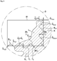
- FIG. 4 shows another detail of Fig. 2 , being centred at the centre of the projection of the eleventh field of view F 11 of the 11 th -beam source.
- the number 11 is just an example and may be generalized.
- determining the 11 th -subtrahend surface S 11 one may again use meandering lines which in this case may be labelled B 11 ,j , B 11 ,k and B 11, l .
- B 11 ,j , B 11 ,k and B 11, l When determining S 11 , the first set and second sets of locations L 1 and L 2 have already been determined and hence the 11 th -intersecting set IS 11 is limited by B 1 ,j' and B 2, j" .
- B 1 ,j' and B 2, j" As can be seen in Fig.
- the example method can be implemented particularly easy, if the sequence of determining the subtrahend surfaces S i is selected based on the ability of the i th -beam source to contribute to fusing the area A.
- a measure for this ability to contribute can be considered as the size of the overlap of their respective fields of view F i with the area A.
- the sequence of determining the subtrahend surfaces S i and hence the sets of locations L i preferably starts with the index representing the beam source having the field of view F i with the smallest overlap with the area A and the indices are preferably sorted such that the
Landscapes
- Engineering & Computer Science (AREA)
- Materials Engineering (AREA)
- Chemical & Material Sciences (AREA)
- Manufacturing & Machinery (AREA)
- Physics & Mathematics (AREA)
- Optics & Photonics (AREA)
- Toxicology (AREA)
- Health & Medical Sciences (AREA)
- Mechanical Engineering (AREA)
- Microelectronics & Electronic Packaging (AREA)
- Plasma & Fusion (AREA)
- General Health & Medical Sciences (AREA)
- Environmental & Geological Engineering (AREA)
- Automation & Control Theory (AREA)
- Laser Beam Processing (AREA)
Claims (20)
- Ein Verfahren zum Herstellen eines Werkstücks, aufweisend- Schmelzen eines Bereichs (A) einer Schicht aus einem schmelzbaren Material durch Bestrahlen der Oberfläche des Bereichs (A) der Schicht unter Verwendung einer Anzahl n, n >_ 2 von mindestens zwei Strahlquellen, um eine entsprechende Anzahl von n Strahlenpunkten auf n Mengen von Stellen (Li ) des Oberflächenbereichs (A) der Schicht zu projizieren, wobei∘ jede Strahlquelle eine vordefinierte Schmelzrate (Ri ) und ein Sichtfeld (Fi ) hat,∘
 ∘ die Indizes von Li , Ri und Fi die entsprechende Strahlenquelle symbolisieren, d. h. 0 < i ≤ n und die Menge aller Strahlenquellen anzeigenden Indizes I = {1, ..., n} ist;dadurch gekennzeichnet, dass das Verfahren weiterhin zumindest folgende Schritte aufweist:1.1. Schätzen einer optimalen Schmelzzeit to (i) und/oder einer Größe eines optimalen Schmelzbereichs für den Bereich
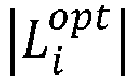 1.2. Bestimmen von Schnittmengen (ISi ) des Oberflächenbereichs (A) und der Sichtfelder (Fi ) für mindestens einen ersten Index i = 1, d. h. Zuordnen von ISi : = A ∩ Fi , zumindest für i= 1;1.3. Vergleich der Größe der Überschneidungsmengen |ISi |) mit dem Produkt der optimalen Schmelzzeit to (i) mit der Schmelzrate Ri der entsprechenden i-ten Strahlenquelle und/oder mit der optimalen Größe der Schmelzfläche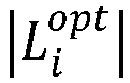
 1.3.1. Bestimmen einer Subtrahend-Oberfläche Si mit Si c ISi und zumindest eines von (1 - αi )(|ISi | - to (i) · Ri ) ≤ |Si | ≤ (1 + αi )(|ISi | - to (i) · Ri ), und

p i ∈ Si, ∃ Fk |p i ∈ Fk , k > i, und1.3.2. Zuordnen von Li : = ISi - Si, und1.4. Schmelzen des schmelzbaren Materials an den Stellen der Menge von Stellen Li unter Verwendung der i-ten Strahlenquelle wird nach Schritt 1.3.2 ausgeführt. - Das Verfahren nach Anspruch 1, dadurch gekennzeichnet, dass, wenn die Beziehung to · Ri < |ISi | und/oder
 2.1. Bestimmen der Subtrahend-Oberfläche Si mit Si ⊂ ISi unter der Bedingung, dass für jedes
p i ∈ Si , ∃ Fk |p i ∈ Fk , k > i, und2.2. Zuordnen von Li : = ISi - Si, und optional2.3. Berechnen einer korrigierten minimalen mittleren Zeit


- Das Verfahren nach Anspruch 1 oder 2, dadurch gekennzeichnet, dass das Verfahren weiterhin Folgendes aufweist:3.1. Setzen von Li : = { } genau dann, wenn ISi = { } und/oder3.2. Wiederholen von zumindest einem der Schritte 1.1, 1.2, 1.3, 2.1, 2.2 und 2.3 für alle verbleibenden i ∈ I, genau dann, wenn ISi ≠ { }.
- Das Verfahren nach einem der vorhergehenden Ansprüche, dadurch gekennzeichnet, dass Schritt 1.3.1 weiterhin Folgendes aufweist:4.1. Definieren zumindest einer ersten mäandernden Linie Bi,j parallel zu einer ersten Richtung
b 1;4.2. Verwenden zumindest der ersten mäandernden Linie Bi,j, um eine erste Grenze der Subtrahend-Oberfläche Si zu bestimmen;4.3. Verschieben der ersten mäandernden Linie in eine zweite Richtungb 2 , welche ΔSi reduziert, wobei ΔSi = |to (i) · Ri - |ISi - Si ||. - Das Verfahren nach Anspruch 4, dadurch gekennzeichnet, dass die erste Richtung und die zweite Richtung linear unabhängig voneinander sind.
- Das Verfahren nach einem der Ansprüche 4 oder 5, dadurch gekennzeichnet, dass
die erste Linie Bj,i eine Mäanderlinie ist, welche parallel zur ersten Richtungb 1 mäandert. - Das Verfahren nach einem der Ansprüche 4 bis 6, dadurch gekennzeichnet, dass
das Schmelzen des schmelzbaren Materials an der Menge von Stellen Li das Schwenken der i-ten Strahlenquelle aufweist, während die i-te Strahlenquelle einen i -ten Strahlenpunkt projiziert, um dadurch den i -ten Strahlenpunkt entlang von Linien zu bewegen, die ein Vielfaches eines Fusionsvektorsv i sind, wobei zumindest eine der mäandernden Linien Bi,j, Bi,k aus verketteten Abschnitten besteht, die abwechselnd orthogonal und parallel zu dem Fusionsvektorv i sind. - Das Verfahren nach einem der vorhergehenden Ansprüche, dadurch gekennzeichnet, dass
es weiterhin, vor dem Bestimmen der Subtrahend-Oberfläche Si, Zuordnen eines Teils Ci des Bereiches A zu einer dedizierten i-ten Strahlenquelle aufweist, wobei die Bedingung zutrifft, dass Ci ⊂ Fi , und dass in Schritt 1.3.1 und/oder 2.1 die Bedingung Si ∩ Ci = { } eingehalten wird. - Das Verfahren nach einem der vorhergehenden Ansprüche, dadurch gekennzeichnet, dass
vor dem Schritt 1.2 die Indizes des Sichtfeldes Fi sortiert werden, um der Bedingung
- Das Verfahren nach einem der vorhergehenden Ansprüche, dadurch gekennzeichnet, dass
vor dem Schritt 1.2 die Indizes des Sichtfeldes Fi sortiert werden, um der Bedingung |ISi | ≤ |ISj | ∀i < j zu genügen und dass die Schritte 1.2 und 1.3 wiederholt werden, während der Wert des Index mit jeder Wiederholung um eins erhöht wird, außer für jene Indizes i, für die ISi = {}. - Das Verfahren nach einem der vorhergehenden Ansprüche, dadurch gekennzeichnet, dass
es das Wiederholen von Schritt 1.2 aufweist, wobei die Schnittmengen ISj für zumindest ein
- Das Verfahren nach einem der vorhergehenden Ansprüche, dadurch gekennzeichnet, dass
das Verfahren weiterhin Herstellen eines Inertgasstroms in eine Strömungsrichtungd über die Oberfläche des Pulverbettes aufweist, wobeid h die Komponente der Strömungsrichtung bezeichnet, die parallel zur Schicht des schmelzbaren Materials ist. - Das Verfahren nach den Ansprüchen 4 und 12, dadurch gekennzeichnet, dass13.1. der parallel zu
d h zwischen einem Endpunktb i,j,e des ersten Abschnittes Bi,j und jedem anderen Punktb i,j von Bi,j gemessene Abstand einmalig ist, d. h. |d h · (b i,j,l -b i,j,e )| ≠ |d h ·b i,j,m -b i,j,e )| ∀b i,j,l,b i,j,m ∈ Bi,b i,j,l ≠b i,j,m oder dass13.2. der orthogonal zu dh zwischen einem Endpunktb i,j,e des ersten Abschnittes Bi,j und jedem anderen Punktb i,j,l von Bi,j gemessene Abstand einmalig ist, d. h. |d o · (b i,i,l -b i,j,e )| ≠ |d o · (b i,j,m -b i,j,e )| ∀b i,j,l,b i,j,m ∈ Bi,b i,j,l ≠b i,j,m · wobeid o ┴d h. - Das Verfahren nach einem der Ansprüche 12 bis 13, dadurch gekennzeichnet, dass
der Vektorv i eine Komponente hat, die der Strömungsrichtungd h des Inertgasstroms entgegengesetzt ist. - Das Verfahren nach einem der Ansprüche 10 bis 14, dadurch gekennzeichnet, dass
es zumindest zwei verschiedene erste Abschnitte Bi,j, Bq,r gibt, welche die Grenzen zwischen benachbarten Mengen von Stellen Li,Lj bzw. Lq,Lr, bilden, wobei ein Endpunkt des ersten Abschnittes SQ i,j ebenso ein Endpunkt des ersten Abschnittes SQq,r ist. - Das Verfahren nach Anspruch 15, dadurch gekennzeichnet, dass entweder die Bedingung 13.1 oder 13.2 auf beide Bi,j und Bq,r .zutrifft.
- Das Verfahren nach Anspruch 16, dadurch gekennzeichnet, dass die Bedingung 13.1 auf beide Bi,j und Bq,r zutrifft und wobei Li,Lj,Lq und Lr jeweils in m Teile L s,1, L s,2, ..., Ls,m, (m ≥ 2) durch Linien, die sich parallel zu
d h erstrecken, unterteilt sind, und wobei |L s,l | = |Ls,n | ± 0.15 · |Ls,n | b's E {i, j, q, r}, l, n ≤ m, l ≠ n, wobei Teile mit demselben zweiten Index parallel zud h ausgerichtet sind und dass nur Teile mit demselben zweiten Index simultan bestrahlt werden. - Das Verfahren nach einem der vorhergehenden Ansprüche, dadurch gekennzeichnet, dass die optimale Schmelzzeit to (i) unter Verwendung der Beziehung


- Ein Speichermedium aufweisend ein Programm, welches, wenn es ausgeführt wird, eine Steuerung einer additiven Fertigungsvorrichtung anweist, das Verfahren nach zumindest einem der vorhergehenden Ansprüche auszuführen.
- Eine additive Fertigungsvorrichtung aufweisend einen Träger, eine Anzahl von n Strahlenquellen, wobei n ≥ 2, zum Schmelzen eines schmelzbaren Materials und eine Steuerung, die konfiguriert ist, um den Betrieb der n Strahlenquellen zu steuern, dadurch gekennzeichnet, dass die Fertigungsvorrichtung weiterhin das Speichermedium nach Anspruch 19 aufweist.
Applications Claiming Priority (2)
| Application Number | Priority Date | Filing Date | Title |
|---|---|---|---|
| DE102021110091 | 2021-04-21 | ||
| PCT/EP2022/059930 WO2022223411A1 (en) | 2021-04-21 | 2022-04-13 | Powder bed fusion additive manufacturing with load balancing for multiple beams |
Publications (3)
| Publication Number | Publication Date |
|---|---|
| EP4121240A1 EP4121240A1 (de) | 2023-01-25 |
| EP4121240B1 true EP4121240B1 (de) | 2024-02-28 |
| EP4121240B9 EP4121240B9 (de) | 2024-06-26 |
Family
ID=81648560
Family Applications (1)
| Application Number | Title | Priority Date | Filing Date |
|---|---|---|---|
| EP22723049.7A Active EP4121240B9 (de) | 2021-04-21 | 2022-04-13 | Generative pulverbettfusionsfertigung mit lastausgleich für mehrere strahlen |
Country Status (5)
| Country | Link |
|---|---|
| US (2) | US12257627B2 (de) |
| EP (1) | EP4121240B9 (de) |
| JP (1) | JP7650370B2 (de) |
| CN (1) | CN117693407B (de) |
| WO (1) | WO2022223411A1 (de) |
Families Citing this family (1)
| Publication number | Priority date | Publication date | Assignee | Title |
|---|---|---|---|---|
| WO2025202045A1 (en) | 2024-03-28 | 2025-10-02 | Nikon Slm Solutions Ag | Scanning path determination in the powder bed fusion process and powder bed fusion apparatus |
Family Cites Families (12)
| Publication number | Priority date | Publication date | Assignee | Title |
|---|---|---|---|---|
| DE102006055055A1 (de) | 2006-11-22 | 2008-05-29 | Eos Gmbh Electro Optical Systems | Vorrichtung zum schichtweisen Herstellen eines dreidimensionalen Objekts |
| DE102013205724A1 (de) | 2013-03-28 | 2014-10-02 | Eos Gmbh Electro Optical Systems | Verfahren und Vorrichtung zum Herstellen eines dreidimensionalen Objekts |
| ES2725889T3 (es) * | 2013-06-10 | 2019-09-30 | Renishaw Plc | Aparato y método de solidificación selectiva por láser |
| GB2520161B (en) | 2014-09-24 | 2015-10-07 | Lpw Technology Ltd | Transport of Powders |
| DE102014016679A1 (de) | 2014-11-12 | 2016-05-12 | Cl Schutzrechtsverwaltungs Gmbh | Verfahren und Vorrichtung zur Belichtungssteuerung einer selektiven Lasersinter- oder Laserschmelzvorrichtung |
| WO2016110440A1 (de) | 2015-01-07 | 2016-07-14 | Eos Gmbh Electro Optical Systems | Vorrichtung und generatives schichtbauverfahren zur herstellung eines dreidimensionalen objekts mit mehrzahligen strahlen |
| CN107635749A (zh) * | 2015-06-10 | 2018-01-26 | Ipg光子公司 | 多光束增材制造 |
| CN106825567B (zh) * | 2017-01-22 | 2018-12-11 | 清华大学 | 电子束选区熔化与电子束切割复合的增材制造方法 |
| DE102018203233A1 (de) | 2018-03-05 | 2019-09-05 | MTU Aero Engines AG | Belichtungsverfahren, Herstellungsverfahren und Vorrichtung zum selektiven Laserschmelzen |
| DE102018110294A1 (de) * | 2018-04-27 | 2019-10-31 | Eos Gmbh Electro Optical Systems | Verfahren und Vorrichtung zur Generierung von Steuerdaten für eine Vorrichtung zur additiven Fertigung |
| JP7407832B2 (ja) | 2019-03-04 | 2024-01-04 | エスエルエム ソルーションズ グループ アーゲー | 制御方法、制御装置及び製造装置 |
| WO2022087043A1 (en) | 2020-10-21 | 2022-04-28 | General Electric Company | Material supply systems and methods for using the same |
-
2022
- 2022-04-13 CN CN202280041812.3A patent/CN117693407B/zh active Active
- 2022-04-13 WO PCT/EP2022/059930 patent/WO2022223411A1/en not_active Ceased
- 2022-04-13 EP EP22723049.7A patent/EP4121240B9/de active Active
- 2022-04-13 JP JP2023565223A patent/JP7650370B2/ja active Active
-
2023
- 2023-10-18 US US18/489,164 patent/US12257627B2/en active Active
-
2025
- 2025-03-20 US US19/085,280 patent/US20250214144A1/en active Pending
Also Published As
| Publication number | Publication date |
|---|---|
| EP4121240A1 (de) | 2023-01-25 |
| US12257627B2 (en) | 2025-03-25 |
| CN117693407A (zh) | 2024-03-12 |
| US20250214144A1 (en) | 2025-07-03 |
| WO2022223411A1 (en) | 2022-10-27 |
| JP7650370B2 (ja) | 2025-03-24 |
| EP4121240B9 (de) | 2024-06-26 |
| JP2024516626A (ja) | 2024-04-16 |
| CN117693407B (zh) | 2025-05-23 |
| US20240246150A1 (en) | 2024-07-25 |
Similar Documents
| Publication | Publication Date | Title |
|---|---|---|
| US6823230B1 (en) | Tool path planning process for component by layered manufacture | |
| US9772620B2 (en) | Generating optimized tool paths and machine commands for beam cutting tools | |
| US20250214144A1 (en) | Power bed fusion additive manufacturing with load balancing for multiple beams | |
| JP7387870B2 (ja) | 板状または管状のワークピースをビーム加工するための方法 | |
| CN116806178B (zh) | 粉末床熔合方法及相关设备 | |
| EP3917757B1 (de) | Optimierungsansatz für lastausgleich und minimierung der aufbauzeit in der generativen fertigung | |
| US12186991B2 (en) | Method for generating an irradiation control data set for an additive manufacturing device | |
| US20180281112A1 (en) | Overlapping border and internal sections of object formed by different am melting beam sources in overlapping field region | |
| US9849544B2 (en) | Laser processing method and laser processing program creation device | |
| US20260084216A1 (en) | Uncertainty quantification or predictive defect model for multi-laser powder bed fusion additive manufacturing | |
| Gokhale et al. | Development of a deposition framework for implementation of a region-based adaptive slicing strategy in arc-based metal additive manufacturing | |
| EP4403362A1 (de) | Herstellungssystem | |
| Frolov | The experience of the portal machine control system modernizing for automatic arc welding and surfacing in a shielded gas | |
| Verbist et al. | A methodology for weld bead geometry and operating conditions determination in Wire Arc Additive Manufacturing | |
| EP4467265A1 (de) | Laser-plume-interaktion für prädiktives defektmodell zur generativen fertigung mittels multilaserpulverbettfusion | |
| EP3393760B1 (de) | Vorrichtung und verfahren zur generativen fertigung | |
| JP2017113825A (ja) | ワイヤ放電加工機 | |
| Zheng et al. | A new strategy to reduce node accumulation in wire-arc directed energy deposition of multi-grid aluminium structures | |
| US20260084215A1 (en) | Method and planning device for planning local selective irradiation of a work region using an energy beam, and method and manufacturing device for additively manufacturing a component from a powder material | |
| Vanmunster et al. | Exploration of synchronized dual-beam laser melting with high speed video imaging | |
| KR101688804B1 (ko) | 스테이지와 스캐너의 이동경로 생성방법 | |
| CN120957828A (zh) | 用于确定接合平面的优化焊接方向的方法;用于确定接合两个部件的优化接合平面的方法;和焊接两个部件的方法 | |
| Mäde et al. | A-prori layer height determination for wire arc additive manufacturing based on weld geometry A-priori-Lagenhöhenbestimmung für drahtbasierte Lichtbogen-Additiv-Schweißverfahren auf Basis der Schweißnahtgeometrie | |
| WO2025202045A1 (en) | Scanning path determination in the powder bed fusion process and powder bed fusion apparatus | |
| CN119525727A (zh) | 激光焊接系统、激光焊接方法及相关装置 |
Legal Events
| Date | Code | Title | Description |
|---|---|---|---|
| STAA | Information on the status of an ep patent application or granted ep patent |
Free format text: STATUS: UNKNOWN |
|
| STAA | Information on the status of an ep patent application or granted ep patent |
Free format text: STATUS: THE INTERNATIONAL PUBLICATION HAS BEEN MADE |
|
| PUAI | Public reference made under article 153(3) epc to a published international application that has entered the european phase |
Free format text: ORIGINAL CODE: 0009012 |
|
| STAA | Information on the status of an ep patent application or granted ep patent |
Free format text: STATUS: REQUEST FOR EXAMINATION WAS MADE |
|
| 17P | Request for examination filed |
Effective date: 20221020 |
|
| AK | Designated contracting states |
Kind code of ref document: A1 Designated state(s): AL AT BE BG CH CY CZ DE DK EE ES FI FR GB GR HR HU IE IS IT LI LT LU LV MC MK MT NL NO PL PT RO RS SE SI SK SM TR |
|
| GRAP | Despatch of communication of intention to grant a patent |
Free format text: ORIGINAL CODE: EPIDOSNIGR1 |
|
| STAA | Information on the status of an ep patent application or granted ep patent |
Free format text: STATUS: GRANT OF PATENT IS INTENDED |
|
| DAV | Request for validation of the european patent (deleted) | ||
| DAX | Request for extension of the european patent (deleted) | ||
| INTG | Intention to grant announced |
Effective date: 20230203 |
|
| GRAS | Grant fee paid |
Free format text: ORIGINAL CODE: EPIDOSNIGR3 |
|
| GRAJ | Information related to disapproval of communication of intention to grant by the applicant or resumption of examination proceedings by the epo deleted |
Free format text: ORIGINAL CODE: EPIDOSDIGR1 |
|
| GRAL | Information related to payment of fee for publishing/printing deleted |
Free format text: ORIGINAL CODE: EPIDOSDIGR3 |
|
| STAA | Information on the status of an ep patent application or granted ep patent |
Free format text: STATUS: REQUEST FOR EXAMINATION WAS MADE |
|
| P01 | Opt-out of the competence of the unified patent court (upc) registered |
Effective date: 20230512 |
|
| INTC | Intention to grant announced (deleted) | ||
| GRAP | Despatch of communication of intention to grant a patent |
Free format text: ORIGINAL CODE: EPIDOSNIGR1 |
|
| STAA | Information on the status of an ep patent application or granted ep patent |
Free format text: STATUS: GRANT OF PATENT IS INTENDED |
|
| INTG | Intention to grant announced |
Effective date: 20230711 |
|
| GRAJ | Information related to disapproval of communication of intention to grant by the applicant or resumption of examination proceedings by the epo deleted |
Free format text: ORIGINAL CODE: EPIDOSDIGR1 |
|
| GRAL | Information related to payment of fee for publishing/printing deleted |
Free format text: ORIGINAL CODE: EPIDOSDIGR3 |
|
| STAA | Information on the status of an ep patent application or granted ep patent |
Free format text: STATUS: REQUEST FOR EXAMINATION WAS MADE |
|
| RAP1 | Party data changed (applicant data changed or rights of an application transferred) |
Owner name: NIKON SLM SOLUTIONS AG |
|
| INTC | Intention to grant announced (deleted) | ||
| GRAP | Despatch of communication of intention to grant a patent |
Free format text: ORIGINAL CODE: EPIDOSNIGR1 |
|
| STAA | Information on the status of an ep patent application or granted ep patent |
Free format text: STATUS: GRANT OF PATENT IS INTENDED |
|
| INTG | Intention to grant announced |
Effective date: 20231124 |
|
| GRAA | (expected) grant |
Free format text: ORIGINAL CODE: 0009210 |
|
| STAA | Information on the status of an ep patent application or granted ep patent |
Free format text: STATUS: THE PATENT HAS BEEN GRANTED |
|
| AK | Designated contracting states |
Kind code of ref document: B1 Designated state(s): AL AT BE BG CH CY CZ DE DK EE ES FI FR GB GR HR HU IE IS IT LI LT LU LV MC MK MT NL NO PL PT RO RS SE SI SK SM TR |
|
| REG | Reference to a national code |
Ref country code: GB Ref legal event code: FG4D |
|
| REG | Reference to a national code |
Ref country code: CH Ref legal event code: EP |
|
| REG | Reference to a national code |
Ref country code: DE Ref legal event code: R096 Ref document number: 602022002152 Country of ref document: DE |
|
| REG | Reference to a national code |
Ref country code: IE Ref legal event code: FG4D |
|
| REG | Reference to a national code |
Ref country code: CH Ref legal event code: PK Free format text: BERICHTIGUNG B9 |
|
| REG | Reference to a national code |
Ref country code: LT Ref legal event code: MG9D |
|
| PG25 | Lapsed in a contracting state [announced via postgrant information from national office to epo] |
Ref country code: IS Free format text: LAPSE BECAUSE OF FAILURE TO SUBMIT A TRANSLATION OF THE DESCRIPTION OR TO PAY THE FEE WITHIN THE PRESCRIBED TIME-LIMIT Effective date: 20240628 |
|
| PG25 | Lapsed in a contracting state [announced via postgrant information from national office to epo] |
Ref country code: LT Free format text: LAPSE BECAUSE OF FAILURE TO SUBMIT A TRANSLATION OF THE DESCRIPTION OR TO PAY THE FEE WITHIN THE PRESCRIBED TIME-LIMIT Effective date: 20240228 |
|
| REG | Reference to a national code |
Ref country code: NL Ref legal event code: FP |
|
| PG25 | Lapsed in a contracting state [announced via postgrant information from national office to epo] |
Ref country code: GR Free format text: LAPSE BECAUSE OF FAILURE TO SUBMIT A TRANSLATION OF THE DESCRIPTION OR TO PAY THE FEE WITHIN THE PRESCRIBED TIME-LIMIT Effective date: 20240529 |
|
| PG25 | Lapsed in a contracting state [announced via postgrant information from national office to epo] |
Ref country code: HR Free format text: LAPSE BECAUSE OF FAILURE TO SUBMIT A TRANSLATION OF THE DESCRIPTION OR TO PAY THE FEE WITHIN THE PRESCRIBED TIME-LIMIT Effective date: 20240228 Ref country code: RS Free format text: LAPSE BECAUSE OF FAILURE TO SUBMIT A TRANSLATION OF THE DESCRIPTION OR TO PAY THE FEE WITHIN THE PRESCRIBED TIME-LIMIT Effective date: 20240528 |
|
| PG25 | Lapsed in a contracting state [announced via postgrant information from national office to epo] |
Ref country code: ES Free format text: LAPSE BECAUSE OF FAILURE TO SUBMIT A TRANSLATION OF THE DESCRIPTION OR TO PAY THE FEE WITHIN THE PRESCRIBED TIME-LIMIT Effective date: 20240228 |
|
| PG25 | Lapsed in a contracting state [announced via postgrant information from national office to epo] |
Ref country code: RS Free format text: LAPSE BECAUSE OF FAILURE TO SUBMIT A TRANSLATION OF THE DESCRIPTION OR TO PAY THE FEE WITHIN THE PRESCRIBED TIME-LIMIT Effective date: 20240528 Ref country code: NO Free format text: LAPSE BECAUSE OF FAILURE TO SUBMIT A TRANSLATION OF THE DESCRIPTION OR TO PAY THE FEE WITHIN THE PRESCRIBED TIME-LIMIT Effective date: 20240528 Ref country code: LT Free format text: LAPSE BECAUSE OF FAILURE TO SUBMIT A TRANSLATION OF THE DESCRIPTION OR TO PAY THE FEE WITHIN THE PRESCRIBED TIME-LIMIT Effective date: 20240228 Ref country code: IS Free format text: LAPSE BECAUSE OF FAILURE TO SUBMIT A TRANSLATION OF THE DESCRIPTION OR TO PAY THE FEE WITHIN THE PRESCRIBED TIME-LIMIT Effective date: 20240628 Ref country code: HR Free format text: LAPSE BECAUSE OF FAILURE TO SUBMIT A TRANSLATION OF THE DESCRIPTION OR TO PAY THE FEE WITHIN THE PRESCRIBED TIME-LIMIT Effective date: 20240228 Ref country code: GR Free format text: LAPSE BECAUSE OF FAILURE TO SUBMIT A TRANSLATION OF THE DESCRIPTION OR TO PAY THE FEE WITHIN THE PRESCRIBED TIME-LIMIT Effective date: 20240529 Ref country code: FI Free format text: LAPSE BECAUSE OF FAILURE TO SUBMIT A TRANSLATION OF THE DESCRIPTION OR TO PAY THE FEE WITHIN THE PRESCRIBED TIME-LIMIT Effective date: 20240228 Ref country code: ES Free format text: LAPSE BECAUSE OF FAILURE TO SUBMIT A TRANSLATION OF THE DESCRIPTION OR TO PAY THE FEE WITHIN THE PRESCRIBED TIME-LIMIT Effective date: 20240228 Ref country code: BG Free format text: LAPSE BECAUSE OF FAILURE TO SUBMIT A TRANSLATION OF THE DESCRIPTION OR TO PAY THE FEE WITHIN THE PRESCRIBED TIME-LIMIT Effective date: 20240228 |
|
| PG25 | Lapsed in a contracting state [announced via postgrant information from national office to epo] |
Ref country code: PT Free format text: LAPSE BECAUSE OF FAILURE TO SUBMIT A TRANSLATION OF THE DESCRIPTION OR TO PAY THE FEE WITHIN THE PRESCRIBED TIME-LIMIT Effective date: 20240628 Ref country code: PL Free format text: LAPSE BECAUSE OF FAILURE TO SUBMIT A TRANSLATION OF THE DESCRIPTION OR TO PAY THE FEE WITHIN THE PRESCRIBED TIME-LIMIT Effective date: 20240228 |
|
| REG | Reference to a national code |
Ref country code: AT Ref legal event code: MK05 Ref document number: 1660790 Country of ref document: AT Kind code of ref document: T Effective date: 20240228 |
|
| PG25 | Lapsed in a contracting state [announced via postgrant information from national office to epo] |
Ref country code: SE Free format text: LAPSE BECAUSE OF FAILURE TO SUBMIT A TRANSLATION OF THE DESCRIPTION OR TO PAY THE FEE WITHIN THE PRESCRIBED TIME-LIMIT Effective date: 20240228 Ref country code: PT Free format text: LAPSE BECAUSE OF FAILURE TO SUBMIT A TRANSLATION OF THE DESCRIPTION OR TO PAY THE FEE WITHIN THE PRESCRIBED TIME-LIMIT Effective date: 20240628 Ref country code: PL Free format text: LAPSE BECAUSE OF FAILURE TO SUBMIT A TRANSLATION OF THE DESCRIPTION OR TO PAY THE FEE WITHIN THE PRESCRIBED TIME-LIMIT Effective date: 20240228 Ref country code: LV Free format text: LAPSE BECAUSE OF FAILURE TO SUBMIT A TRANSLATION OF THE DESCRIPTION OR TO PAY THE FEE WITHIN THE PRESCRIBED TIME-LIMIT Effective date: 20240228 |
|
| PG25 | Lapsed in a contracting state [announced via postgrant information from national office to epo] |
Ref country code: DK Free format text: LAPSE BECAUSE OF FAILURE TO SUBMIT A TRANSLATION OF THE DESCRIPTION OR TO PAY THE FEE WITHIN THE PRESCRIBED TIME-LIMIT Effective date: 20240228 |
|
| PG25 | Lapsed in a contracting state [announced via postgrant information from national office to epo] |
Ref country code: SM Free format text: LAPSE BECAUSE OF FAILURE TO SUBMIT A TRANSLATION OF THE DESCRIPTION OR TO PAY THE FEE WITHIN THE PRESCRIBED TIME-LIMIT Effective date: 20240228 |
|
| PG25 | Lapsed in a contracting state [announced via postgrant information from national office to epo] |
Ref country code: CZ Free format text: LAPSE BECAUSE OF FAILURE TO SUBMIT A TRANSLATION OF THE DESCRIPTION OR TO PAY THE FEE WITHIN THE PRESCRIBED TIME-LIMIT Effective date: 20240228 Ref country code: EE Free format text: LAPSE BECAUSE OF FAILURE TO SUBMIT A TRANSLATION OF THE DESCRIPTION OR TO PAY THE FEE WITHIN THE PRESCRIBED TIME-LIMIT Effective date: 20240228 |
|
| PG25 | Lapsed in a contracting state [announced via postgrant information from national office to epo] |
Ref country code: AT Free format text: LAPSE BECAUSE OF FAILURE TO SUBMIT A TRANSLATION OF THE DESCRIPTION OR TO PAY THE FEE WITHIN THE PRESCRIBED TIME-LIMIT Effective date: 20240228 |
|
| PG25 | Lapsed in a contracting state [announced via postgrant information from national office to epo] |
Ref country code: SK Free format text: LAPSE BECAUSE OF FAILURE TO SUBMIT A TRANSLATION OF THE DESCRIPTION OR TO PAY THE FEE WITHIN THE PRESCRIBED TIME-LIMIT Effective date: 20240228 |
|
| PG25 | Lapsed in a contracting state [announced via postgrant information from national office to epo] |
Ref country code: SM Free format text: LAPSE BECAUSE OF FAILURE TO SUBMIT A TRANSLATION OF THE DESCRIPTION OR TO PAY THE FEE WITHIN THE PRESCRIBED TIME-LIMIT Effective date: 20240228 Ref country code: SK Free format text: LAPSE BECAUSE OF FAILURE TO SUBMIT A TRANSLATION OF THE DESCRIPTION OR TO PAY THE FEE WITHIN THE PRESCRIBED TIME-LIMIT Effective date: 20240228 Ref country code: RO Free format text: LAPSE BECAUSE OF FAILURE TO SUBMIT A TRANSLATION OF THE DESCRIPTION OR TO PAY THE FEE WITHIN THE PRESCRIBED TIME-LIMIT Effective date: 20240228 Ref country code: EE Free format text: LAPSE BECAUSE OF FAILURE TO SUBMIT A TRANSLATION OF THE DESCRIPTION OR TO PAY THE FEE WITHIN THE PRESCRIBED TIME-LIMIT Effective date: 20240228 Ref country code: DK Free format text: LAPSE BECAUSE OF FAILURE TO SUBMIT A TRANSLATION OF THE DESCRIPTION OR TO PAY THE FEE WITHIN THE PRESCRIBED TIME-LIMIT Effective date: 20240228 Ref country code: CZ Free format text: LAPSE BECAUSE OF FAILURE TO SUBMIT A TRANSLATION OF THE DESCRIPTION OR TO PAY THE FEE WITHIN THE PRESCRIBED TIME-LIMIT Effective date: 20240228 Ref country code: AT Free format text: LAPSE BECAUSE OF FAILURE TO SUBMIT A TRANSLATION OF THE DESCRIPTION OR TO PAY THE FEE WITHIN THE PRESCRIBED TIME-LIMIT Effective date: 20240228 |
|
| PG25 | Lapsed in a contracting state [announced via postgrant information from national office to epo] |
Ref country code: MC Free format text: LAPSE BECAUSE OF FAILURE TO SUBMIT A TRANSLATION OF THE DESCRIPTION OR TO PAY THE FEE WITHIN THE PRESCRIBED TIME-LIMIT Effective date: 20240228 |
|
| PG25 | Lapsed in a contracting state [announced via postgrant information from national office to epo] |
Ref country code: MC Free format text: LAPSE BECAUSE OF FAILURE TO SUBMIT A TRANSLATION OF THE DESCRIPTION OR TO PAY THE FEE WITHIN THE PRESCRIBED TIME-LIMIT Effective date: 20240228 |
|
| REG | Reference to a national code |
Ref country code: DE Ref legal event code: R097 Ref document number: 602022002152 Country of ref document: DE |
|
| PG25 | Lapsed in a contracting state [announced via postgrant information from national office to epo] |
Ref country code: LU Free format text: LAPSE BECAUSE OF NON-PAYMENT OF DUE FEES Effective date: 20240413 |
|
| PG25 | Lapsed in a contracting state [announced via postgrant information from national office to epo] |
Ref country code: LU Free format text: LAPSE BECAUSE OF NON-PAYMENT OF DUE FEES Effective date: 20240413 |
|
| PLBE | No opposition filed within time limit |
Free format text: ORIGINAL CODE: 0009261 |
|
| STAA | Information on the status of an ep patent application or granted ep patent |
Free format text: STATUS: NO OPPOSITION FILED WITHIN TIME LIMIT |
|
| 26N | No opposition filed |
Effective date: 20241129 |
|
| PG25 | Lapsed in a contracting state [announced via postgrant information from national office to epo] |
Ref country code: IE Free format text: LAPSE BECAUSE OF NON-PAYMENT OF DUE FEES Effective date: 20240413 |
|
| PG25 | Lapsed in a contracting state [announced via postgrant information from national office to epo] |
Ref country code: SI Free format text: LAPSE BECAUSE OF FAILURE TO SUBMIT A TRANSLATION OF THE DESCRIPTION OR TO PAY THE FEE WITHIN THE PRESCRIBED TIME-LIMIT Effective date: 20240228 |
|
| PGFP | Annual fee paid to national office [announced via postgrant information from national office to epo] |
Ref country code: NL Payment date: 20250422 Year of fee payment: 4 |
|
| PGFP | Annual fee paid to national office [announced via postgrant information from national office to epo] |
Ref country code: DE Payment date: 20250417 Year of fee payment: 4 |
|
| PGFP | Annual fee paid to national office [announced via postgrant information from national office to epo] |
Ref country code: IT Payment date: 20250430 Year of fee payment: 4 Ref country code: BE Payment date: 20250422 Year of fee payment: 4 |
|
| PGFP | Annual fee paid to national office [announced via postgrant information from national office to epo] |
Ref country code: FR Payment date: 20250422 Year of fee payment: 4 |
|
| PG25 | Lapsed in a contracting state [announced via postgrant information from national office to epo] |
Ref country code: CY Free format text: LAPSE BECAUSE OF FAILURE TO SUBMIT A TRANSLATION OF THE DESCRIPTION OR TO PAY THE FEE WITHIN THE PRESCRIBED TIME-LIMIT; INVALID AB INITIO Effective date: 20220413 |
|
| PG25 | Lapsed in a contracting state [announced via postgrant information from national office to epo] |
Ref country code: HU Free format text: LAPSE BECAUSE OF FAILURE TO SUBMIT A TRANSLATION OF THE DESCRIPTION OR TO PAY THE FEE WITHIN THE PRESCRIBED TIME-LIMIT; INVALID AB INITIO Effective date: 20220413 |
|
| REG | Reference to a national code |
Ref country code: CH Ref legal event code: H13 Free format text: ST27 STATUS EVENT CODE: U-0-0-H10-H13 (AS PROVIDED BY THE NATIONAL OFFICE) Effective date: 20251125 |
|
| PG25 | Lapsed in a contracting state [announced via postgrant information from national office to epo] |
Ref country code: CH Free format text: LAPSE BECAUSE OF NON-PAYMENT OF DUE FEES Effective date: 20250430 |
|
| PGFP | Annual fee paid to national office [announced via postgrant information from national office to epo] |
Ref country code: GB Payment date: 20260324 Year of fee payment: 5 |