EP4121229B1 - Device for manufacturing a weave - Google Patents
Device for manufacturing a weave Download PDFInfo
- Publication number
- EP4121229B1 EP4121229B1 EP21713724.9A EP21713724A EP4121229B1 EP 4121229 B1 EP4121229 B1 EP 4121229B1 EP 21713724 A EP21713724 A EP 21713724A EP 4121229 B1 EP4121229 B1 EP 4121229B1
- Authority
- EP
- European Patent Office
- Prior art keywords
- wire
- longitudinal
- wire spool
- weave
- cogwheel
- Prior art date
- Legal status (The legal status is an assumption and is not a legal conclusion. Google has not performed a legal analysis and makes no representation as to the accuracy of the status listed.)
- Active
Links
Images


Classifications
-
- B—PERFORMING OPERATIONS; TRANSPORTING
- B21—MECHANICAL METAL-WORKING WITHOUT ESSENTIALLY REMOVING MATERIAL; PUNCHING METAL
- B21F—WORKING OR PROCESSING OF METAL WIRE
- B21F27/00—Making wire network, i.e. wire nets
- B21F27/02—Making wire network, i.e. wire nets without additional connecting elements or material at crossings, e.g. connected by knitting
-
- D—TEXTILES; PAPER
- D04—BRAIDING; LACE-MAKING; KNITTING; TRIMMINGS; NON-WOVEN FABRICS
- D04C—BRAIDING OR MANUFACTURE OF LACE, INCLUDING BOBBIN-NET OR CARBONISED LACE; BRAIDING MACHINES; BRAID; LACE
- D04C3/00—Braiding or lacing machines
- D04C3/02—Braiding or lacing machines with spool carriers guided by track plates or by bobbin heads exclusively
- D04C3/10—Braiding or lacing machines with spool carriers guided by track plates or by bobbin heads exclusively with means for forming edge loops, ears, or eyes
-
- B—PERFORMING OPERATIONS; TRANSPORTING
- B21—MECHANICAL METAL-WORKING WITHOUT ESSENTIALLY REMOVING MATERIAL; PUNCHING METAL
- B21F—WORKING OR PROCESSING OF METAL WIRE
- B21F15/00—Connecting wire to wire or other metallic material or objects; Connecting parts by means of wire
- B21F15/02—Connecting wire to wire or other metallic material or objects; Connecting parts by means of wire wire with wire
- B21F15/04—Connecting wire to wire or other metallic material or objects; Connecting parts by means of wire wire with wire without additional connecting elements or material, e.g. by twisting
-
- B—PERFORMING OPERATIONS; TRANSPORTING
- B21—MECHANICAL METAL-WORKING WITHOUT ESSENTIALLY REMOVING MATERIAL; PUNCHING METAL
- B21F—WORKING OR PROCESSING OF METAL WIRE
- B21F33/00—Tools or devices specially designed for handling or processing wire fabrics or the like
- B21F33/002—Coiling or packing wire network
-
- B—PERFORMING OPERATIONS; TRANSPORTING
- B64—AIRCRAFT; AVIATION; COSMONAUTICS
- B64F—GROUND OR AIRCRAFT-CARRIER-DECK INSTALLATIONS SPECIALLY ADAPTED FOR USE IN CONNECTION WITH AIRCRAFT; DESIGNING, MANUFACTURING, ASSEMBLING, CLEANING, MAINTAINING OR REPAIRING AIRCRAFT, NOT OTHERWISE PROVIDED FOR; HANDLING, TRANSPORTING, TESTING OR INSPECTING AIRCRAFT COMPONENTS, NOT OTHERWISE PROVIDED FOR
- B64F5/00—Designing, manufacturing, assembling, cleaning, maintaining or repairing aircraft, not otherwise provided for; Handling, transporting, testing or inspecting aircraft components, not otherwise provided for
-
- B—PERFORMING OPERATIONS; TRANSPORTING
- B64—AIRCRAFT; AVIATION; COSMONAUTICS
- B64G—COSMONAUTICS; VEHICLES OR EQUIPMENT THEREFOR
- B64G1/00—Cosmonautic vehicles
- B64G1/22—Parts of, or equipment specially adapted for fitting in or to, cosmonautic vehicles
- B64G1/64—Systems for coupling or separating cosmonautic vehicles or parts thereof, e.g. docking arrangements
- B64G1/648—Tethers
-
- D—TEXTILES; PAPER
- D04—BRAIDING; LACE-MAKING; KNITTING; TRIMMINGS; NON-WOVEN FABRICS
- D04C—BRAIDING OR MANUFACTURE OF LACE, INCLUDING BOBBIN-NET OR CARBONISED LACE; BRAIDING MACHINES; BRAID; LACE
- D04C1/00—Braid or lace, e.g. pillow-lace; Processes for the manufacture thereof
- D04C1/02—Braid or lace, e.g. pillow-lace; Processes for the manufacture thereof made from particular materials
-
- D—TEXTILES; PAPER
- D04—BRAIDING; LACE-MAKING; KNITTING; TRIMMINGS; NON-WOVEN FABRICS
- D04C—BRAIDING OR MANUFACTURE OF LACE, INCLUDING BOBBIN-NET OR CARBONISED LACE; BRAIDING MACHINES; BRAID; LACE
- D04C1/00—Braid or lace, e.g. pillow-lace; Processes for the manufacture thereof
- D04C1/06—Braid or lace serving particular purposes
-
- D—TEXTILES; PAPER
- D04—BRAIDING; LACE-MAKING; KNITTING; TRIMMINGS; NON-WOVEN FABRICS
- D04C—BRAIDING OR MANUFACTURE OF LACE, INCLUDING BOBBIN-NET OR CARBONISED LACE; BRAIDING MACHINES; BRAID; LACE
- D04C3/00—Braiding or lacing machines
- D04C3/02—Braiding or lacing machines with spool carriers guided by track plates or by bobbin heads exclusively
- D04C3/24—Devices for controlling spool carriers to obtain patterns, e.g. devices on guides or track plates
-
- D—TEXTILES; PAPER
- D04—BRAIDING; LACE-MAKING; KNITTING; TRIMMINGS; NON-WOVEN FABRICS
- D04C—BRAIDING OR MANUFACTURE OF LACE, INCLUDING BOBBIN-NET OR CARBONISED LACE; BRAIDING MACHINES; BRAID; LACE
- D04C3/00—Braiding or lacing machines
- D04C3/48—Auxiliary devices
-
- D—TEXTILES; PAPER
- D04—BRAIDING; LACE-MAKING; KNITTING; TRIMMINGS; NON-WOVEN FABRICS
- D04C—BRAIDING OR MANUFACTURE OF LACE, INCLUDING BOBBIN-NET OR CARBONISED LACE; BRAIDING MACHINES; BRAID; LACE
- D04C5/00—Twist or bobbin-net lace-making machines
- D04C5/06—Machines for making twist-lace fabrics
-
- B—PERFORMING OPERATIONS; TRANSPORTING
- B64—AIRCRAFT; AVIATION; COSMONAUTICS
- B64G—COSMONAUTICS; VEHICLES OR EQUIPMENT THEREFOR
- B64G1/00—Cosmonautic vehicles
- B64G1/22—Parts of, or equipment specially adapted for fitting in or to, cosmonautic vehicles
- B64G1/40—Arrangements or adaptations of propulsion systems
- B64G1/407—Solar sailing
-
- D—TEXTILES; PAPER
- D10—INDEXING SCHEME ASSOCIATED WITH SUBLASSES OF SECTION D, RELATING TO TEXTILES
- D10B—INDEXING SCHEME ASSOCIATED WITH SUBLASSES OF SECTION D, RELATING TO TEXTILES
- D10B2101/00—Inorganic fibres
- D10B2101/20—Metallic fibres
-
- D—TEXTILES; PAPER
- D10—INDEXING SCHEME ASSOCIATED WITH SUBLASSES OF SECTION D, RELATING TO TEXTILES
- D10B—INDEXING SCHEME ASSOCIATED WITH SUBLASSES OF SECTION D, RELATING TO TEXTILES
- D10B2505/00—Industrial
- D10B2505/12—Vehicles
-
- H—ELECTRICITY
- H01—ELECTRIC ELEMENTS
- H01B—CABLES; CONDUCTORS; INSULATORS; SELECTION OF MATERIALS FOR THEIR CONDUCTIVE, INSULATING OR DIELECTRIC PROPERTIES
- H01B1/00—Conductors or conductive bodies characterised by the conductive materials; Selection of materials as conductors
- H01B1/02—Conductors or conductive bodies characterised by the conductive materials; Selection of materials as conductors mainly consisting of metals or alloys
Definitions
- the present invention relates to a system for manufacturing of fabrics, ropes, cables and nets, and more particularly to a system for manufacturing a weave made of wires.
- the electric sail is a new space propulsion concept which uses the solar wind momentum for producing thrust.
- a full-scale electric sail consists of many long and thin conducting tethers i.e. weaves made of wires.
- the spacecraft contains a solar-powered electron gun which is used to keep the spacecraft and the wires in a high positive potential.
- the electric field of the wires extends into the surrounding solar wind plasma, which enables the solar wind ions to detect the wires as rather thick and wide obstacles.
- a technical concept exists for deploying the wires in a relatively simple way and guiding the resulting spacecraft electrically.
- Some of the problems associated with the electric sail is how to manufacture the weaves fast, reliably and cost-efficiently, and while in the spacecraft, the weaves can be deployed easily to its full length.
- JPS5224489U1 on which the preamble of claim 1 is based
- JP2002273537A , US523415A , US743806A , US612400A and US6173922B1 disclose different types of devices for manufacturing a weave.
- the pattern of the weave should be designed so that if a meteor or space debris damages part of the weave, it will not begin unwinding itself.
- An object of the present invention to provide a system for manufacturing a weave to overcome the above problems.
- the objects of the invention are achieved by the system which is characterized by what is stated in the independent claim.
- the preferred embodiments of the invention are disclosed in the dependent claims.
- the invention is based on the idea of having a system of manufacturing a weave made of longitudinal wires and a crossing wire forming a loop around each longitudinal wire.
- Advantages of the system of the invention are that a joint between two thin wires is reliable to manufacture automatically and with steady quality, the weave is tolerant to different environments in space and different conditions between the process from manufacture of the weave to the launch to space.
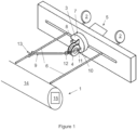
- Figure 1 illustrates an embodiment of a system for manufacturing a weave.
- the system comprises a winder 1, at least two wire spools 2, a wire spool carrier 3 and additional wire spool 4 releasably attached to the wire spool carrier 3 and an actuator 5.
- the wire spools 2 are arranged to release longitudinal wires 6 to the winder 1, wherein each wire spool 2 releases one single longitudinal wire 6.
- Distance between said longitudinal wires 6 is predetermined but adjustable, and to facilitate at keeping the distance constant during operation, hollow tubes (not shown in Figures) may be utilized to guide the longitudinal wires 6 from the wire spools 2 toward the winder 1.
- the distance between the longitudinal wires 6 may be 5 to 8 cm, for instance, and each wire spool 2 may contain kilometres long wire, which is typically 2 km long but not limited to it. Some wire spools 2 may contain up to 7-10 km long wires.
- the distance between the longitudinal wires 6 may be adjusted by adjusting the distance between their respective wire spools 2.
- the wire spool carrier 3 comprises a wheel 7.
- the wheel 7 is a cogwheel, though in all implementations this is not necessary that the wheel 7 is provided with gear coupling, as the actuator 5 may rotate the wheel 7 via an axle.
- the cogwheel 7 comprises a gear coupling, such as inserted teeth or cogs, and a slit 8 extending through the cogwheel 7 from a centre of the wire spool carrier 3 to the circumference.
- the slit 8 should be wider than the hollow tube to allow the hollow tube to pass through the slit 8.
- the cogwheel 7 may have a helix angle making it a helical gear.
- the cogwheel 7 can be for instance 3-5 cm in diameter, making the slit 8 1,5-2,5 cm long.
- the additional wire spool 4 is releasably attached to the wire spool carrier 3 and arranged to release a crossing wire 9.
- the additional wire spool 4 may be arranged with a spool holder 10 which can be releasably attached to a protrusion of the wire spool carrier 3 by means of a screw and nut, for instance.
- An additional guide 11 may be attached to the wire spool carrier 3 for guiding the crossing wire 9 from the additional wire spool 4 through a hole 12.
- the guide 11 is arranged to steer the crossing wire 9 from the additional wire spool 4 with a steady speed and tension.
- An opening can be arranged next to the hole 12 to facilitate the crossing wire 9 forming a loop 13 around the longitudinal wire 6.
- the term "loop" refers to a section of a wire that is wound at least once around another wire.
- the guide 11 is not necessary.
- the actuator 5 is configured to move the wire spool carrier 3 between the longitudinal wires 6 such way that the additional wire spool 4 in turns moves to each longitudinal wire 6 to a position where the respective longitudinal wire 6 is located in the slit 8 of the wire spool carrier 3 at which stage the cogwheel 7 rotates around said respective longitudinal wire 6 to form the loop 13.
- the wire spool carrier 3 can rotate for instance 2-4 rotations around the longitudinal wire 6. Then the cogwheel 7 moves towards a following longitudinal wire 6 in such way that a predetermined path of the crossing wire 9 from the additional wire spool 4 of the wire spool carrier 3 forms the weave with the longitudinal wires 6 from the wire spools 2.
- the actuator 5 may comprise a power source, control system and electric motor, for instance.
- the winder 1 is provided for reeling the manufactured weave to a rotating reel 14 which may be connected to a winding motor 15.
- actuation of the winding motor 15 is timed with the movements of the wire spool carrier 3 in such way that when the wire spool carrier 3 is moving between the longitudinal wires 6, the winding motor 15 is configured to wind the weave on the rotating reel 14, and when the wire spool carrier 3 is rotating around the longitudinal wire 6, the winding motor 15 is configured to halt the winding.
- the longitudinal wires 6 from the wire spools 2 may have a different diameter than the crossing wire 9 from the wire spool carrier 3.
- the longitudinal wire 6 may have a diameter of 40-80 microns and the crossing wire 9 may have 20-50 microns.
- all the wires can have a same diameter, which may range from 20 to 80 microns.
- the wires are made from an electrically conductive material, such as aluminium or copper. Aluminium is advantageous in Low Earth Orbit (LEO) satellites as it resists atomic oxygen due to its oxidized surface and copper is usable in deep space applications, where atomic oxygen is not prevalent.
- LEO Low Earth Orbit
- Figure 2 illustrates a second embodiment of the system for manufacturing a weave.
- the embodiment is very similar to the one explained in connection with Figure 1 . Therefore, the embodiment of Figure 2 is mainly explained by pointing out the differences between these embodiments.
- a second cogwheel 16 is connected to the meshing cogwheel 7 of the wire spool carrier 3 in such way that the second cogwheel 16 is arranged to rotate the cogwheel 7 of the wire spool carrier 3 by transferring torque from the actuator 5.
- the actuator 5 may comprise a cogwheel motor 25 connected to the second cogwheel 16 for rotating the second cogwheel 16 clockwise or anticlockwise.
- the actuator 5 further comprises a linear transfer component 17, such as a drive belt or ball screw, and a linear rail configuration 18 moving the wire spool carrier 3 and the second cogwheel 16 transversally in relation to the longitudinal wires 6.
- the drive belt may be a timing belt with teeth molded onto its inner surface and designed to run over matching toothed pulleys or sprockets.
- a linear transfer motor 19 connected to the toothed pulley or sprocket is configured to transform the rotational motion to linear motion of the drive belt.
- the ball screw transforms rotational motion to linear motion with minimal friction and is made to close tolerances and therefore suitable for use in situations requiring high precision.
- the linear rail configuration 18 in this instance may be a frame, wherein the actuator 5 and wire spools 2 are arranged on one side of the frame and the wire spool carrier 3 and the second cogwheel 16 are arranged on other side of the frame so that the longitudinal wires 6 can pass through the frame via an elongated slot within the frame.
- the linear rail configuration 18 is arranged to move together with the wire spool carrier 3, second cogwheel 16, cogwheel motor 25, linear transfer component 17 and linear transfer motor 19.
- the linear rail configuration 18 may be surrounded by a support structure (not shown in Figures) which is stationary in relation to the wire spool carriers 2 while the linear rail configuration 18 moves transversally within the support structure.
- rotational torque of the cogwheel motor 25 to rotate the wire spool carrier 3 is transmitted via the gear coupling of the second cogwheel 16 and the cogwheel 7 of the wire spool carrier 3.
- This type of rotational torque transmission works also with the helical gear profile since there are multiple points of teeth contact during the rotation.
- Required torque to rotate the wire spool carrier 3 is so low that the performance loss in the torque transmission due to partial contact is negligible.
- Figure 3 illustrates a third embodiment of the system for manufacturing a weave.
- the embodiment is very similar to the one explained in connection with Figure 1 . Therefore, the embodiment of Figure 3 is mainly explained by pointing out the differences between these embodiments.
- the system further comprises a pair of rollers 20 arranged in parallel to receive the weave in between them to compress the loops 13 before reeling the weave to the rotating reel 14. This compression flattens the weave into a plane such that the weave is more compressed during the winding which saves space and bonds the loops 13 around longitudinal wires 6. The bonding adds more contact surface between the loops 13 and the longitudinal wires 6.
- this bonding can be arranged by melting the loops 13 together with the longitudinal wires 6 above the melting temperature of the wires 6, 9.
- Figure 4 illustrates another embodiment of the actuator 5 of the system for manufacturing a weave.
- the rest of the system is very similar to the one explained in connection with Figure 1 . Therefore, the embodiment of Figure 4 is mainly explained by pointing out the differences of the actuator 5.
- the second cogwheel 16, the cogwheel motor 25, the linear transfer component 17, the linear rail configuration 18 and the linear transfer motor 19 are replaced by two parallel longitudinal screws 21 on opposite sides of the wire spool carrier 3 and a separately operated motor 22 for each longitudinal screw 21.
- the longitudinal screws 21 together with their rotary motors 22 actuate rotation movement and transversal movement of the wire spool carrier 3 between the longitudinal wires 6.
- Each parallel longitudinal screw 21 has a helix angle meshing with the circumference of the cogwheel 7 of the wire spool carrier 3 in such way that a first longitudinal screw 21 is above the cogwheel 7 and a second longitudinal screw 21 is below the cogwheel 7.
- the wire spool carrier 3 When the two parallel longitudinal screws 21 have a different direction of rotation but a same speed, the wire spool carrier 3 is arranged to perform rotation movement, and when the two parallel longitudinal screws 21 have a same direction of rotation and a same speed, the wire spool carrier 3 is arranged to perform transversal movement.
- the advantage of this embodiment is to have a lightweight system while achieving high production speeds without harmful vibrations and deflections or wear of moving components.
- the previous embodiments relate to 2-dimensional weave patterns. However, manufacturing a 3-dimensional weave pattern is not excluded.
- the wire spool carrier 3 can be carried by an open-ended grabbing mechanism, for example a robotic arm, and can pass the wire spool carrier 3 to another actuator. This mechanism is suited for both 2-dimensional and 3-dimensional weave patterns and is not physically constrained in any 3-dimensional axis or orientation. This implementation is possible to combine with other embodiments.
- the system can produce different topologies of weaves which enable the weave to maintain integrity in space conditions. Countering space environmental constraints such as atomic oxygen, and micrometeorites as well as minimizing surface area to minimize surface charges and currents forming into the weave. Minimizing launch weight but maximizing length are constraints to match. Multiple longitudinal wires and 2 or 3 dimensionalities in the structure are advantageous, as is minimizing wire surface area by using as thin wires as possible. Two dimensional topologies can be extended to three dimensions by adding a third carrier, for instance.
Landscapes
- Engineering & Computer Science (AREA)
- Textile Engineering (AREA)
- Mechanical Engineering (AREA)
- Manufacturing & Machinery (AREA)
- Aviation & Aerospace Engineering (AREA)
- Remote Sensing (AREA)
- Transportation (AREA)
- Transmission Devices (AREA)
- Woven Fabrics (AREA)
Description
- The present invention relates to a system for manufacturing of fabrics, ropes, cables and nets, and more particularly to a system for manufacturing a weave made of wires.
- The electric sail is a new space propulsion concept which uses the solar wind momentum for producing thrust. A full-scale electric sail consists of many long and thin conducting tethers i.e. weaves made of wires. The spacecraft contains a solar-powered electron gun which is used to keep the spacecraft and the wires in a high positive potential. The electric field of the wires extends into the surrounding solar wind plasma, which enables the solar wind ions to detect the wires as rather thick and wide obstacles. A technical concept exists for deploying the wires in a relatively simple way and guiding the resulting spacecraft electrically.
- Some of the problems associated with the electric sail is how to manufacture the weaves fast, reliably and cost-efficiently, and while in the spacecraft, the weaves can be deployed easily to its full length. For instance,
JPS5224489U1 claim 1 is based,JP2002273537A US523415A ,US743806A ,US612400A andUS6173922B1 disclose different types of devices for manufacturing a weave. The pattern of the weave should be designed so that if a meteor or space debris damages part of the weave, it will not begin unwinding itself. - Manufacturing these patterns has been difficult for multiple reasons. The extremely thin metallic wires, such as less than 50 microns, are fragile, so the manufacturing mechanism should contact or deform or both the individual wires and the completed weave as little as possible. The strain on the wires and the weave should also vary as little as possible during the manufacturing process in order to achieve steady and predictable quality.
- An object of the present invention to provide a system for manufacturing a weave to overcome the above problems. The objects of the invention are achieved by the system which is characterized by what is stated in the independent claim. The preferred embodiments of the invention are disclosed in the dependent claims.
- The invention is based on the idea of having a system of manufacturing a weave made of longitudinal wires and a crossing wire forming a loop around each longitudinal wire.
- Advantages of the system of the invention are that a joint between two thin wires is reliable to manufacture automatically and with steady quality, the weave is tolerant to different environments in space and different conditions between the process from manufacture of the weave to the launch to space.
- In the following the invention will be described in greater detail by means of preferred embodiments with reference to the accompanying drawings, in which
-
Figure 1 illustrates a first embodiment of a system for manufacturing a weave; -
Figure 2 illustrates a second embodiment of the system for manufacturing the weave; -
Figure 3 illustrates a third embodiment of the system for manufacturing the weave; -
Figure 4 illustrates another embodiment of a part of the system for manufacturing the weave. -
Figure 1 illustrates an embodiment of a system for manufacturing a weave. The system comprises awinder 1, at least twowire spools 2, awire spool carrier 3 andadditional wire spool 4 releasably attached to thewire spool carrier 3 and anactuator 5. - The
wire spools 2 are arranged to releaselongitudinal wires 6 to thewinder 1, wherein eachwire spool 2 releases one singlelongitudinal wire 6. Distance between saidlongitudinal wires 6 is predetermined but adjustable, and to facilitate at keeping the distance constant during operation, hollow tubes (not shown in Figures) may be utilized to guide thelongitudinal wires 6 from thewire spools 2 toward thewinder 1. The distance between thelongitudinal wires 6 may be 5 to 8 cm, for instance, and eachwire spool 2 may contain kilometres long wire, which is typically 2 km long but not limited to it. Somewire spools 2 may contain up to 7-10 km long wires. The distance between thelongitudinal wires 6 may be adjusted by adjusting the distance between theirrespective wire spools 2. - The
wire spool carrier 3 comprises a wheel 7. In the following, it will be by example be assumed that the wheel 7 is a cogwheel, though in all implementations this is not necessary that the wheel 7 is provided with gear coupling, as theactuator 5 may rotate the wheel 7 via an axle. In this implementation the cogwheel 7 comprises a gear coupling, such as inserted teeth or cogs, and a slit 8 extending through the cogwheel 7 from a centre of thewire spool carrier 3 to the circumference. The slit 8 should be wider than the hollow tube to allow the hollow tube to pass through the slit 8. The cogwheel 7 may have a helix angle making it a helical gear. The cogwheel 7 can be for instance 3-5 cm in diameter, making the slit 8 1,5-2,5 cm long. - The
additional wire spool 4 is releasably attached to thewire spool carrier 3 and arranged to release a crossing wire 9. Theadditional wire spool 4 may be arranged with aspool holder 10 which can be releasably attached to a protrusion of thewire spool carrier 3 by means of a screw and nut, for instance. - An
additional guide 11 may be attached to thewire spool carrier 3 for guiding the crossing wire 9 from theadditional wire spool 4 through ahole 12. Theguide 11 is arranged to steer the crossing wire 9 from theadditional wire spool 4 with a steady speed and tension. An opening can be arranged next to thehole 12 to facilitate the crossing wire 9 forming aloop 13 around thelongitudinal wire 6. In this context, the term "loop" refers to a section of a wire that is wound at least once around another wire. However, in some embodiments, theguide 11 is not necessary. - The
actuator 5 is configured to move thewire spool carrier 3 between thelongitudinal wires 6 such way that theadditional wire spool 4 in turns moves to eachlongitudinal wire 6 to a position where the respectivelongitudinal wire 6 is located in the slit 8 of thewire spool carrier 3 at which stage the cogwheel 7 rotates around said respectivelongitudinal wire 6 to form theloop 13. Thewire spool carrier 3 can rotate for instance 2-4 rotations around thelongitudinal wire 6. Then the cogwheel 7 moves towards a followinglongitudinal wire 6 in such way that a predetermined path of the crossing wire 9 from theadditional wire spool 4 of thewire spool carrier 3 forms the weave with thelongitudinal wires 6 from thewire spools 2. Theactuator 5 may comprise a power source, control system and electric motor, for instance. - In the
Figure 1 , only twowire spools 2 andlongitudinal wires 6 are shown. However, more than twowire spools 2 andlongitudinal wires 6 may be arranged to weave a wider weave. - The
winder 1 is provided for reeling the manufactured weave to a rotatingreel 14 which may be connected to a windingmotor 15. When the weave with desired length is completed, thereel 14 can be removed from thewinder 1. In some embodiments, actuation of thewinding motor 15 is timed with the movements of thewire spool carrier 3 in such way that when thewire spool carrier 3 is moving between thelongitudinal wires 6, thewinding motor 15 is configured to wind the weave on the rotatingreel 14, and when thewire spool carrier 3 is rotating around thelongitudinal wire 6, thewinding motor 15 is configured to halt the winding. - The
longitudinal wires 6 from thewire spools 2 may have a different diameter than the crossing wire 9 from thewire spool carrier 3. For example, thelongitudinal wire 6 may have a diameter of 40-80 microns and the crossing wire 9 may have 20-50 microns. Alternatively, all the wires can have a same diameter, which may range from 20 to 80 microns. The wires are made from an electrically conductive material, such as aluminium or copper. Aluminium is advantageous in Low Earth Orbit (LEO) satellites as it resists atomic oxygen due to its oxidized surface and copper is usable in deep space applications, where atomic oxygen is not prevalent. -
Figure 2 illustrates a second embodiment of the system for manufacturing a weave. The embodiment is very similar to the one explained in connection withFigure 1 . Therefore, the embodiment ofFigure 2 is mainly explained by pointing out the differences between these embodiments. - A
second cogwheel 16 is connected to the meshing cogwheel 7 of thewire spool carrier 3 in such way that thesecond cogwheel 16 is arranged to rotate the cogwheel 7 of thewire spool carrier 3 by transferring torque from theactuator 5. Theactuator 5 may comprise acogwheel motor 25 connected to thesecond cogwheel 16 for rotating thesecond cogwheel 16 clockwise or anticlockwise. Theactuator 5 further comprises alinear transfer component 17, such as a drive belt or ball screw, and alinear rail configuration 18 moving thewire spool carrier 3 and thesecond cogwheel 16 transversally in relation to thelongitudinal wires 6. - The drive belt may be a timing belt with teeth molded onto its inner surface and designed to run over matching toothed pulleys or sprockets. A
linear transfer motor 19 connected to the toothed pulley or sprocket is configured to transform the rotational motion to linear motion of the drive belt. The ball screw transforms rotational motion to linear motion with minimal friction and is made to close tolerances and therefore suitable for use in situations requiring high precision. - The
linear rail configuration 18 in this instance may be a frame, wherein theactuator 5 andwire spools 2 are arranged on one side of the frame and thewire spool carrier 3 and thesecond cogwheel 16 are arranged on other side of the frame so that thelongitudinal wires 6 can pass through the frame via an elongated slot within the frame. Thelinear rail configuration 18 is arranged to move together with thewire spool carrier 3,second cogwheel 16,cogwheel motor 25,linear transfer component 17 andlinear transfer motor 19. Thelinear rail configuration 18 may be surrounded by a support structure (not shown in Figures) which is stationary in relation to thewire spool carriers 2 while thelinear rail configuration 18 moves transversally within the support structure. - With this setup, it is possible to use different
wire spool carrier 3 models and weave patterns without requiring extensive modifications to the system platform. In this embodiment, rotational torque of thecogwheel motor 25 to rotate thewire spool carrier 3 is transmitted via the gear coupling of thesecond cogwheel 16 and the cogwheel 7 of thewire spool carrier 3. This type of rotational torque transmission works also with the helical gear profile since there are multiple points of teeth contact during the rotation. Required torque to rotate thewire spool carrier 3 is so low that the performance loss in the torque transmission due to partial contact is negligible. -
Figure 3 illustrates a third embodiment of the system for manufacturing a weave. The embodiment is very similar to the one explained in connection withFigure 1 . Therefore, the embodiment ofFigure 3 is mainly explained by pointing out the differences between these embodiments. - In
Figure 3 , the system further comprises a pair ofrollers 20 arranged in parallel to receive the weave in between them to compress theloops 13 before reeling the weave to the rotatingreel 14. This compression flattens the weave into a plane such that the weave is more compressed during the winding which saves space and bonds theloops 13 aroundlongitudinal wires 6. The bonding adds more contact surface between theloops 13 and thelongitudinal wires 6. - Alternatively, this bonding can be arranged by melting the
loops 13 together with thelongitudinal wires 6 above the melting temperature of thewires 6, 9. When a single wire brakes due to micrometeorites, for instance, the rest of the weave remain intact due to the resilience of the bonding. -
Figure 4 illustrates another embodiment of theactuator 5 of the system for manufacturing a weave. The rest of the system is very similar to the one explained in connection withFigure 1 . Therefore, the embodiment ofFigure 4 is mainly explained by pointing out the differences of theactuator 5. - In this embodiment, the
second cogwheel 16, thecogwheel motor 25, thelinear transfer component 17, thelinear rail configuration 18 and thelinear transfer motor 19 are replaced by two parallellongitudinal screws 21 on opposite sides of thewire spool carrier 3 and a separately operatedmotor 22 for eachlongitudinal screw 21. Thelongitudinal screws 21 together with theirrotary motors 22 actuate rotation movement and transversal movement of thewire spool carrier 3 between thelongitudinal wires 6. - Each parallel
longitudinal screw 21 has a helix angle meshing with the circumference of the cogwheel 7 of thewire spool carrier 3 in such way that a firstlongitudinal screw 21 is above the cogwheel 7 and a secondlongitudinal screw 21 is below the cogwheel 7. - When the two parallel
longitudinal screws 21 have a different direction of rotation but a same speed, thewire spool carrier 3 is arranged to perform rotation movement, and when the two parallellongitudinal screws 21 have a same direction of rotation and a same speed, thewire spool carrier 3 is arranged to perform transversal movement. - The advantage of this embodiment is to have a lightweight system while achieving high production speeds without harmful vibrations and deflections or wear of moving components.
- The previous embodiments relate to 2-dimensional weave patterns. However, manufacturing a 3-dimensional weave pattern is not excluded. Generally, the
wire spool carrier 3 can be carried by an open-ended grabbing mechanism, for example a robotic arm, and can pass thewire spool carrier 3 to another actuator. This mechanism is suited for both 2-dimensional and 3-dimensional weave patterns and is not physically constrained in any 3-dimensional axis or orientation. This implementation is possible to combine with other embodiments. - The system can produce different topologies of weaves which enable the weave to maintain integrity in space conditions. Countering space environmental constraints such as atomic oxygen, and micrometeorites as well as minimizing surface area to minimize surface charges and currents forming into the weave. Minimizing launch weight but maximizing length are constraints to match. Multiple longitudinal wires and 2 or 3 dimensionalities in the structure are advantageous, as is minimizing wire surface area by using as thin wires as possible. Two dimensional topologies can be extended to three dimensions by adding a third carrier, for instance.
Claims (8)
- A system for manufacturing a weave, the system comprising:a winder (1) for reeling the manufactured weave to a rotating reel (14),wire spools (2), comprising longitudinal wires (6), arranged to release said longitudinal wires (6) to said winder (1), characterized in that the system further comprisesa wire spool carrier (3) comprising a wheel (7) and a slit (8) extending through the wheel (7) from a centre of the wire spool carrier (3) to the circumference,an additional wire spool (4), comprising a crossing wire (9), releasably attached to the wire spool carrier (3) and arranged to release said crossing wire (9), andan actuator (5) configured to move, in use, the wire spool carrier (3) between the longitudinal wires (6) such that the additional wire spool (4) in turns moves to each longitudinal wire (6) to a position where the respective longitudinal wire (6) is located in said slit (8) at which stage the wheel (7) is rotatable around said respective longitudinal wire (6) to wound a section of said crossing wire (9) at least once around said respective longitudinal wire (6) before moving towards a following longitudinal wire (6) in such a way that a predetermined path of the crossing wire (9) from the additional wire spool (4) forms the weave with the longitudinal wires (6) from the wire spools (2).
- The system according to claim 1, wherein said wheel (7) is a cogwheel and the system further comprisesa second cogwheel (16) connected to the wire spool carrier (3), andthe actuator (5) further comprising a linear transfer component (17) and a linear rail configuration (18) moving the wire spool carrier (3) and the second cogwheel (16) transversally in relation to the longitudinal wires (6).
- The system according to claim 1, wherein said wheel (7) is a cogwheel and the system further comprisestwo parallel longitudinal screws (21) on opposite sides of the cogwheel (7) of the wire spool carrier (3), anda separately operated motor (22) for each longitudinal screw (21) which together the motors (22) actuate rotation movement and transversal movement of the wire spool carrier (3) between the longitudinal wires (6).
- The system according to any preceding claims 1-3, wherein the longitudinal wires (6) from the wire spools (2) have a different diameter than the crossing wire (9) from the additional wire spool (4).
- The system according to any preceding claims 1-4, wherein the diameter of the wires (6, 9) is 20-80 microns.
- The system according to any preceding claims 1-5, wherein the system further comprises a pair of rollers (20) arranged in parallel to receive the weave in between them to compress the weave before reeling to the rotating reel (14).
- The system according to any preceding claims 1-6, wherein the wire (6, 9) is made from electrically conductive material.
- The system according to claim 7, wherein the wire (6, 9) is made from one of aluminium or copper.
Applications Claiming Priority (2)
| Application Number | Priority Date | Filing Date | Title |
|---|---|---|---|
| FI20205268A FI129043B (en) | 2020-03-16 | 2020-03-16 | Device for manufacturing a weave |
| PCT/FI2021/050185 WO2021186106A1 (en) | 2020-03-16 | 2021-03-15 | Device for manufacturing a weave |
Publications (3)
| Publication Number | Publication Date |
|---|---|
| EP4121229A1 EP4121229A1 (en) | 2023-01-25 |
| EP4121229C0 EP4121229C0 (en) | 2023-11-01 |
| EP4121229B1 true EP4121229B1 (en) | 2023-11-01 |
Family
ID=75143671
Family Applications (1)
| Application Number | Title | Priority Date | Filing Date |
|---|---|---|---|
| EP21713724.9A Active EP4121229B1 (en) | 2020-03-16 | 2021-03-15 | Device for manufacturing a weave |
Country Status (5)
| Country | Link |
|---|---|
| US (1) | US12054859B2 (en) |
| EP (1) | EP4121229B1 (en) |
| ES (1) | ES2967658T3 (en) |
| FI (1) | FI129043B (en) |
| WO (1) | WO2021186106A1 (en) |
Family Cites Families (37)
| Publication number | Priority date | Publication date | Assignee | Title |
|---|---|---|---|---|
| US1465554A (en) * | 1923-08-21 | klein | ||
| US523415A (en) * | 1894-07-24 | Machine for weavinb cross-wires in wire fences | ||
| US157536A (en) * | 1874-12-08 | Improvement in apparatus for weaving hair | ||
| US612400A (en) * | 1898-10-18 | cochrane | ||
| US743806A (en) * | 1902-12-13 | 1903-11-10 | Blassie Baumgartner | Wire-fence machine. |
| US843299A (en) * | 1904-06-11 | 1907-02-05 | Michigan Woven Wire Fence Co | Wire-fabric-weaving machine. |
| US983985A (en) * | 1907-10-09 | 1911-02-14 | Allen C Shimer | Wire-fabric-making machine. |
| US1141382A (en) * | 1911-02-06 | 1915-06-01 | Adolph L De Leeuw | Circular braider. |
| GB191213508A (en) | 1912-06-10 | 1913-02-13 | Shepshed Lace Mfg Company Ltd | Improvements in the Manufacture of Lace on Lace Braiding Machines and in Machines therefor. |
| US1095176A (en) * | 1913-05-29 | 1914-04-28 | Nashawena Mills | Leno-weaving. |
| US2223317A (en) * | 1938-11-07 | 1940-11-26 | Ewing Dev Company | Weaving machine |
| US3222016A (en) * | 1964-03-26 | 1965-12-07 | Jay D Boone | Variable porosity fabric for aeronautical decelerator |
| US3578529A (en) * | 1968-05-27 | 1971-05-11 | Arthur Kenneth Baker | Apparatus for producing reinforced plastics material articles |
| US3633850A (en) * | 1969-01-06 | 1972-01-11 | Lewis Feldman | Flexible sail rotor devices |
| JPS5341579Y2 (en) * | 1975-07-31 | 1978-10-06 | ||
| JPS5224489A (en) | 1975-08-20 | 1977-02-23 | Toyota Motor Corp | Radar |
| US4517715A (en) * | 1982-04-13 | 1985-05-21 | Toray Industries, Inc. | Chenille woven or knitted fabric and process for producing the same |
| US5659477A (en) * | 1994-12-28 | 1997-08-19 | Collins; Charles Michael | Self reproducing fundamental fabricating machines (F-Units) |
| US6173922B1 (en) * | 1997-04-22 | 2001-01-16 | Robert P. Hoyt | Failure resistant multiline tether |
| AU6046000A (en) * | 1999-03-22 | 2000-10-16 | Ilc Dover, Inc. | Method of linear actuation by inflation and apparatus therefor |
| US6431497B1 (en) * | 2000-09-08 | 2002-08-13 | Robert P. Hoyt | Failure resistant multiline tether |
| JP2002273537A (en) * | 2001-03-16 | 2002-09-25 | Murata Mach Ltd | Wire-like body pulling mechanism |
| WO2003004356A2 (en) * | 2001-07-06 | 2003-01-16 | Team Encounter, Llc | Space craft and methods for space travel |
| CN108425170B (en) * | 2004-11-09 | 2021-02-26 | 得克萨斯大学体系董事会 | Manufacture and use of nanofiber yarns, tapes and sheets |
| US7913954B2 (en) * | 2006-03-10 | 2011-03-29 | Star Technology And Research, Inc. | Electrodynamic structure |
| JP4335974B1 (en) | 2008-09-11 | 2009-09-30 | 徹 菅間 | Transmission medium |
| GB0818523D0 (en) * | 2008-10-09 | 2008-11-19 | Univ Exeter | Fibrous assembly |
| US7858055B2 (en) * | 2008-12-18 | 2010-12-28 | Kimberly-Clark Worldwide, Inc. | Moisture sensitive auxetic material |
| GB201107152D0 (en) * | 2011-04-28 | 2011-06-08 | Leonard Philip | Textile thread or fibre |
| DE102011107208A1 (en) * | 2011-07-13 | 2013-01-17 | Frank Ellinghaus | Mobile solar glider space powerhouse and coupled solar glider power plants for space-based energy generation and generation |
| GB201210691D0 (en) * | 2012-06-15 | 2012-08-01 | Mmt Textiles Ltd | Active fibre |
| US10213965B2 (en) * | 2013-11-25 | 2019-02-26 | Tethers Unlimited Inc | Architecture, methods, and apparatus for additive manufacturing and assembly of sparse structures, multifunctional structures, and components for space and terrestrial systems |
| US20150247267A1 (en) * | 2014-03-03 | 2015-09-03 | Comfortex Window Fashions | Variable transparency fabric, window shade including same and related method |
| EP3433492B1 (en) * | 2016-03-21 | 2024-10-02 | Board Of Regents, The University Of Texas System | Actuating textiles containing polymer fiber muscles |
| EP3468868B1 (en) * | 2016-06-14 | 2021-05-19 | Blomquist, Richard | Spacecraft and control method |
| WO2019093520A1 (en) | 2017-11-13 | 2019-05-16 | 国立研究開発法人宇宙航空研究開発機構 | Net, tether accommodating device, and method for producing net |
| JP2019090146A (en) * | 2017-11-13 | 2019-06-13 | 国立研究開発法人宇宙航空研究開発機構 | Net, device for housing tether, and method of producing net |
-
2020
- 2020-03-16 FI FI20205268A patent/FI129043B/en active IP Right Grant
-
2021
- 2021-03-15 US US17/911,846 patent/US12054859B2/en active Active
- 2021-03-15 EP EP21713724.9A patent/EP4121229B1/en active Active
- 2021-03-15 ES ES21713724T patent/ES2967658T3/en active Active
- 2021-03-15 WO PCT/FI2021/050185 patent/WO2021186106A1/en not_active Ceased
Also Published As
| Publication number | Publication date |
|---|---|
| WO2021186106A1 (en) | 2021-09-23 |
| FI20205268A1 (en) | 2021-05-31 |
| EP4121229C0 (en) | 2023-11-01 |
| US12054859B2 (en) | 2024-08-06 |
| US20230151520A1 (en) | 2023-05-18 |
| EP4121229A1 (en) | 2023-01-25 |
| ES2967658T3 (en) | 2024-05-03 |
| FI129043B (en) | 2021-05-31 |
Similar Documents
| Publication | Publication Date | Title |
|---|---|---|
| EP1354670B1 (en) | Multi-finger hand device | |
| US1983962A (en) | Power transmission mechanism | |
| EP3055726B1 (en) | Near-linear drive systems for positioning reflectors | |
| US10213965B2 (en) | Architecture, methods, and apparatus for additive manufacturing and assembly of sparse structures, multifunctional structures, and components for space and terrestrial systems | |
| JP4797020B2 (en) | Actuator | |
| US20170373379A1 (en) | Multi ret actuator having a relay configuration with positioning and driving motors | |
| US12054859B2 (en) | Device for manufacturing a weave | |
| CN113172645B (en) | a continuum robot | |
| EP0097562A2 (en) | Telescopic transfer device, particularly for industrial robots | |
| CA2642423A1 (en) | Rotary to linear transmission | |
| US4864784A (en) | Mast extending and rotating apparatus | |
| EP3213999B1 (en) | Deployment and pointing device | |
| EP4291492B1 (en) | Boom system for a satellite | |
| US6622580B1 (en) | Backlash-free speed reducing device | |
| US7412910B2 (en) | Mechanism for transforming a rotational movement into a linear movement | |
| US12060924B2 (en) | Device for winding/unwinding a link | |
| EP4347397B1 (en) | Remote control system for a magnus-effect aircraft | |
| WO2023051975A1 (en) | Robot, robotic system, manipulation device and method for manipulating objects | |
| CN105798900B (en) | Rope driving decoupling mechanism and its decoupling method based on train | |
| US7758364B1 (en) | Rotary positioning | |
| US20190257012A1 (en) | Armouring machine assembly with an adjustable guide plate | |
| JP2003130167A (en) | Conversion device of straight line motion to turning motion | |
| US8262009B2 (en) | System for electrical cable management in limited rotation applications | |
| FR2572560A1 (en) | Movement unit for machine manipulator | |
| AU2018221306B2 (en) | System for transferring a magnetic link |
Legal Events
| Date | Code | Title | Description |
|---|---|---|---|
| STAA | Information on the status of an ep patent application or granted ep patent |
Free format text: STATUS: UNKNOWN |
|
| STAA | Information on the status of an ep patent application or granted ep patent |
Free format text: STATUS: THE INTERNATIONAL PUBLICATION HAS BEEN MADE |
|
| PUAI | Public reference made under article 153(3) epc to a published international application that has entered the european phase |
Free format text: ORIGINAL CODE: 0009012 |
|
| STAA | Information on the status of an ep patent application or granted ep patent |
Free format text: STATUS: REQUEST FOR EXAMINATION WAS MADE |
|
| 17P | Request for examination filed |
Effective date: 20221011 |
|
| AK | Designated contracting states |
Kind code of ref document: A1 Designated state(s): AL AT BE BG CH CY CZ DE DK EE ES FI FR GB GR HR HU IE IS IT LI LT LU LV MC MK MT NL NO PL PT RO RS SE SI SK SM TR |
|
| GRAP | Despatch of communication of intention to grant a patent |
Free format text: ORIGINAL CODE: EPIDOSNIGR1 |
|
| STAA | Information on the status of an ep patent application or granted ep patent |
Free format text: STATUS: GRANT OF PATENT IS INTENDED |
|
| DAV | Request for validation of the european patent (deleted) | ||
| DAX | Request for extension of the european patent (deleted) | ||
| INTG | Intention to grant announced |
Effective date: 20230524 |
|
| GRAS | Grant fee paid |
Free format text: ORIGINAL CODE: EPIDOSNIGR3 |
|
| GRAA | (expected) grant |
Free format text: ORIGINAL CODE: 0009210 |
|
| STAA | Information on the status of an ep patent application or granted ep patent |
Free format text: STATUS: THE PATENT HAS BEEN GRANTED |
|
| AK | Designated contracting states |
Kind code of ref document: B1 Designated state(s): AL AT BE BG CH CY CZ DE DK EE ES FI FR GB GR HR HU IE IS IT LI LT LU LV MC MK MT NL NO PL PT RO RS SE SI SK SM TR |
|
| REG | Reference to a national code |
Ref country code: GB Ref legal event code: FG4D |
|
| REG | Reference to a national code |
Ref country code: CH Ref legal event code: EP |
|
| REG | Reference to a national code |
Ref country code: IE Ref legal event code: FG4D |
|
| REG | Reference to a national code |
Ref country code: DE Ref legal event code: R096 Ref document number: 602021006458 Country of ref document: DE |
|
| U01 | Request for unitary effect filed |
Effective date: 20231127 |
|
| U07 | Unitary effect registered |
Designated state(s): AT BE BG DE DK EE FI FR IT LT LU LV MT NL PT SE SI Effective date: 20231201 |
|
| REG | Reference to a national code |
Ref country code: NO Ref legal event code: T2 Effective date: 20231101 |
|
| PG25 | Lapsed in a contracting state [announced via postgrant information from national office to epo] |
Ref country code: GR Free format text: LAPSE BECAUSE OF FAILURE TO SUBMIT A TRANSLATION OF THE DESCRIPTION OR TO PAY THE FEE WITHIN THE PRESCRIBED TIME-LIMIT Effective date: 20240202 |
|
| PG25 | Lapsed in a contracting state [announced via postgrant information from national office to epo] |
Ref country code: IS Free format text: LAPSE BECAUSE OF FAILURE TO SUBMIT A TRANSLATION OF THE DESCRIPTION OR TO PAY THE FEE WITHIN THE PRESCRIBED TIME-LIMIT Effective date: 20240301 |
|
| U20 | Renewal fee for the european patent with unitary effect paid |
Year of fee payment: 4 Effective date: 20240312 |
|
| PG25 | Lapsed in a contracting state [announced via postgrant information from national office to epo] |
Ref country code: IS Free format text: LAPSE BECAUSE OF FAILURE TO SUBMIT A TRANSLATION OF THE DESCRIPTION OR TO PAY THE FEE WITHIN THE PRESCRIBED TIME-LIMIT Effective date: 20240301 Ref country code: GR Free format text: LAPSE BECAUSE OF FAILURE TO SUBMIT A TRANSLATION OF THE DESCRIPTION OR TO PAY THE FEE WITHIN THE PRESCRIBED TIME-LIMIT Effective date: 20240202 |
|
| REG | Reference to a national code |
Ref country code: ES Ref legal event code: FG2A Ref document number: 2967658 Country of ref document: ES Kind code of ref document: T3 Effective date: 20240503 |
|
| PG25 | Lapsed in a contracting state [announced via postgrant information from national office to epo] |
Ref country code: RS Free format text: LAPSE BECAUSE OF FAILURE TO SUBMIT A TRANSLATION OF THE DESCRIPTION OR TO PAY THE FEE WITHIN THE PRESCRIBED TIME-LIMIT Effective date: 20231101 Ref country code: PL Free format text: LAPSE BECAUSE OF FAILURE TO SUBMIT A TRANSLATION OF THE DESCRIPTION OR TO PAY THE FEE WITHIN THE PRESCRIBED TIME-LIMIT Effective date: 20231101 Ref country code: HR Free format text: LAPSE BECAUSE OF FAILURE TO SUBMIT A TRANSLATION OF THE DESCRIPTION OR TO PAY THE FEE WITHIN THE PRESCRIBED TIME-LIMIT Effective date: 20231101 |
|
| PG25 | Lapsed in a contracting state [announced via postgrant information from national office to epo] |
Ref country code: CZ Free format text: LAPSE BECAUSE OF FAILURE TO SUBMIT A TRANSLATION OF THE DESCRIPTION OR TO PAY THE FEE WITHIN THE PRESCRIBED TIME-LIMIT Effective date: 20231101 |
|
| PG25 | Lapsed in a contracting state [announced via postgrant information from national office to epo] |
Ref country code: SK Free format text: LAPSE BECAUSE OF FAILURE TO SUBMIT A TRANSLATION OF THE DESCRIPTION OR TO PAY THE FEE WITHIN THE PRESCRIBED TIME-LIMIT Effective date: 20231101 |
|
| PG25 | Lapsed in a contracting state [announced via postgrant information from national office to epo] |
Ref country code: SM Free format text: LAPSE BECAUSE OF FAILURE TO SUBMIT A TRANSLATION OF THE DESCRIPTION OR TO PAY THE FEE WITHIN THE PRESCRIBED TIME-LIMIT Effective date: 20231101 Ref country code: SK Free format text: LAPSE BECAUSE OF FAILURE TO SUBMIT A TRANSLATION OF THE DESCRIPTION OR TO PAY THE FEE WITHIN THE PRESCRIBED TIME-LIMIT Effective date: 20231101 Ref country code: CZ Free format text: LAPSE BECAUSE OF FAILURE TO SUBMIT A TRANSLATION OF THE DESCRIPTION OR TO PAY THE FEE WITHIN THE PRESCRIBED TIME-LIMIT Effective date: 20231101 |
|
| REG | Reference to a national code |
Ref country code: DE Ref legal event code: R097 Ref document number: 602021006458 Country of ref document: DE |
|
| PLBE | No opposition filed within time limit |
Free format text: ORIGINAL CODE: 0009261 |
|
| STAA | Information on the status of an ep patent application or granted ep patent |
Free format text: STATUS: NO OPPOSITION FILED WITHIN TIME LIMIT |
|
| 26N | No opposition filed |
Effective date: 20240802 |
|
| REG | Reference to a national code |
Ref country code: CH Ref legal event code: PL |
|
| PG25 | Lapsed in a contracting state [announced via postgrant information from national office to epo] |
Ref country code: MC Free format text: LAPSE BECAUSE OF FAILURE TO SUBMIT A TRANSLATION OF THE DESCRIPTION OR TO PAY THE FEE WITHIN THE PRESCRIBED TIME-LIMIT Effective date: 20231101 |
|
| PG25 | Lapsed in a contracting state [announced via postgrant information from national office to epo] |
Ref country code: MC Free format text: LAPSE BECAUSE OF FAILURE TO SUBMIT A TRANSLATION OF THE DESCRIPTION OR TO PAY THE FEE WITHIN THE PRESCRIBED TIME-LIMIT Effective date: 20231101 |
|
| PG25 | Lapsed in a contracting state [announced via postgrant information from national office to epo] |
Ref country code: IE Free format text: LAPSE BECAUSE OF NON-PAYMENT OF DUE FEES Effective date: 20240315 |
|
| PG25 | Lapsed in a contracting state [announced via postgrant information from national office to epo] |
Ref country code: IE Free format text: LAPSE BECAUSE OF NON-PAYMENT OF DUE FEES Effective date: 20240315 Ref country code: CH Free format text: LAPSE BECAUSE OF NON-PAYMENT OF DUE FEES Effective date: 20240331 |
|
| U20 | Renewal fee for the european patent with unitary effect paid |
Year of fee payment: 5 Effective date: 20250312 |
|
| PGFP | Annual fee paid to national office [announced via postgrant information from national office to epo] |
Ref country code: ES Payment date: 20250604 Year of fee payment: 5 |
|
| PG25 | Lapsed in a contracting state [announced via postgrant information from national office to epo] |
Ref country code: RO Free format text: LAPSE BECAUSE OF FAILURE TO SUBMIT A TRANSLATION OF THE DESCRIPTION OR TO PAY THE FEE WITHIN THE PRESCRIBED TIME-LIMIT Effective date: 20231101 |
|
| PG25 | Lapsed in a contracting state [announced via postgrant information from national office to epo] |
Ref country code: CY Free format text: LAPSE BECAUSE OF FAILURE TO SUBMIT A TRANSLATION OF THE DESCRIPTION OR TO PAY THE FEE WITHIN THE PRESCRIBED TIME-LIMIT; INVALID AB INITIO Effective date: 20210315 |
|
| PG25 | Lapsed in a contracting state [announced via postgrant information from national office to epo] |
Ref country code: HU Free format text: LAPSE BECAUSE OF FAILURE TO SUBMIT A TRANSLATION OF THE DESCRIPTION OR TO PAY THE FEE WITHIN THE PRESCRIBED TIME-LIMIT; INVALID AB INITIO Effective date: 20210315 |
|
| PG25 | Lapsed in a contracting state [announced via postgrant information from national office to epo] |
Ref country code: TR Free format text: LAPSE BECAUSE OF FAILURE TO SUBMIT A TRANSLATION OF THE DESCRIPTION OR TO PAY THE FEE WITHIN THE PRESCRIBED TIME-LIMIT Effective date: 20231101 |
|
| U20 | Renewal fee for the european patent with unitary effect paid |
Year of fee payment: 6 Effective date: 20260304 |
|
| PGFP | Annual fee paid to national office [announced via postgrant information from national office to epo] |
Ref country code: GB Payment date: 20260330 Year of fee payment: 6 |
|
| PGFP | Annual fee paid to national office [announced via postgrant information from national office to epo] |
Ref country code: NO Payment date: 20260324 Year of fee payment: 6 |