EP4120987B1 - Entferntes zentrales schultergelenk für ein schulterstützendes exoskelett - Google Patents
Entferntes zentrales schultergelenk für ein schulterstützendes exoskelett Download PDFInfo
- Publication number
- EP4120987B1 EP4120987B1 EP21771767.7A EP21771767A EP4120987B1 EP 4120987 B1 EP4120987 B1 EP 4120987B1 EP 21771767 A EP21771767 A EP 21771767A EP 4120987 B1 EP4120987 B1 EP 4120987B1
- Authority
- EP
- European Patent Office
- Prior art keywords
- segment
- axis
- center joint
- remote
- remote center
- Prior art date
- Legal status (The legal status is an assumption and is not a legal conclusion. Google has not performed a legal analysis and makes no representation as to the accuracy of the status listed.)
- Active
Links
Images


Classifications
-
- A—HUMAN NECESSITIES
- A61—MEDICAL OR VETERINARY SCIENCE; HYGIENE
- A61H—PHYSICAL THERAPY APPARATUS, e.g. DEVICES FOR LOCATING OR STIMULATING REFLEX POINTS IN THE BODY; ARTIFICIAL RESPIRATION; MASSAGE; BATHING DEVICES FOR SPECIAL THERAPEUTIC OR HYGIENIC PURPOSES OR SPECIFIC PARTS OF THE BODY
- A61H1/00—Apparatus for passive exercising; Vibrating apparatus; Chiropractic devices, e.g. body impacting devices, external devices for briefly extending or aligning unbroken bones
- A61H1/02—Stretching or bending or torsioning apparatus for exercising
- A61H1/0274—Stretching or bending or torsioning apparatus for exercising for the upper limbs
- A61H1/0281—Shoulder
-
- A—HUMAN NECESSITIES
- A61—MEDICAL OR VETERINARY SCIENCE; HYGIENE
- A61H—PHYSICAL THERAPY APPARATUS, e.g. DEVICES FOR LOCATING OR STIMULATING REFLEX POINTS IN THE BODY; ARTIFICIAL RESPIRATION; MASSAGE; BATHING DEVICES FOR SPECIAL THERAPEUTIC OR HYGIENIC PURPOSES OR SPECIFIC PARTS OF THE BODY
- A61H1/00—Apparatus for passive exercising; Vibrating apparatus; Chiropractic devices, e.g. body impacting devices, external devices for briefly extending or aligning unbroken bones
- A61H1/02—Stretching or bending or torsioning apparatus for exercising
- A61H1/0292—Stretching or bending or torsioning apparatus for exercising for the spinal column
- A61H1/0296—Neck
-
- B—PERFORMING OPERATIONS; TRANSPORTING
- B25—HAND TOOLS; PORTABLE POWER-DRIVEN TOOLS; MANIPULATORS
- B25J—MANIPULATORS; CHAMBERS PROVIDED WITH MANIPULATION DEVICES
- B25J9/00—Programme-controlled manipulators
- B25J9/0006—Exoskeletons, i.e. resembling a human figure
-
- B—PERFORMING OPERATIONS; TRANSPORTING
- B25—HAND TOOLS; PORTABLE POWER-DRIVEN TOOLS; MANIPULATORS
- B25J—MANIPULATORS; CHAMBERS PROVIDED WITH MANIPULATION DEVICES
- B25J9/00—Programme-controlled manipulators
- B25J9/003—Programme-controlled manipulators having parallel kinematics
- B25J9/0045—Programme-controlled manipulators having parallel kinematics with kinematics chains having a rotary joint at the base
- B25J9/0048—Programme-controlled manipulators having parallel kinematics with kinematics chains having a rotary joint at the base with kinematics chains of the type rotary-rotary-rotary
-
- A—HUMAN NECESSITIES
- A61—MEDICAL OR VETERINARY SCIENCE; HYGIENE
- A61H—PHYSICAL THERAPY APPARATUS, e.g. DEVICES FOR LOCATING OR STIMULATING REFLEX POINTS IN THE BODY; ARTIFICIAL RESPIRATION; MASSAGE; BATHING DEVICES FOR SPECIAL THERAPEUTIC OR HYGIENIC PURPOSES OR SPECIFIC PARTS OF THE BODY
- A61H2201/00—Characteristics of apparatus not provided for in the preceding codes
- A61H2201/12—Driving means
- A61H2201/1207—Driving means with electric or magnetic drive
-
- A—HUMAN NECESSITIES
- A61—MEDICAL OR VETERINARY SCIENCE; HYGIENE
- A61H—PHYSICAL THERAPY APPARATUS, e.g. DEVICES FOR LOCATING OR STIMULATING REFLEX POINTS IN THE BODY; ARTIFICIAL RESPIRATION; MASSAGE; BATHING DEVICES FOR SPECIAL THERAPEUTIC OR HYGIENIC PURPOSES OR SPECIFIC PARTS OF THE BODY
- A61H2201/00—Characteristics of apparatus not provided for in the preceding codes
- A61H2201/16—Physical interface with patient
- A61H2201/1602—Physical interface with patient kind of interface, e.g. head rest, knee support or lumbar support
- A61H2201/1609—Neck
-
- A—HUMAN NECESSITIES
- A61—MEDICAL OR VETERINARY SCIENCE; HYGIENE
- A61H—PHYSICAL THERAPY APPARATUS, e.g. DEVICES FOR LOCATING OR STIMULATING REFLEX POINTS IN THE BODY; ARTIFICIAL RESPIRATION; MASSAGE; BATHING DEVICES FOR SPECIAL THERAPEUTIC OR HYGIENIC PURPOSES OR SPECIFIC PARTS OF THE BODY
- A61H2201/00—Characteristics of apparatus not provided for in the preceding codes
- A61H2201/16—Physical interface with patient
- A61H2201/1602—Physical interface with patient kind of interface, e.g. head rest, knee support or lumbar support
- A61H2201/1614—Shoulder, e.g. for neck stretching
- A61H2201/1616—Holding means therefor
-
- A—HUMAN NECESSITIES
- A61—MEDICAL OR VETERINARY SCIENCE; HYGIENE
- A61H—PHYSICAL THERAPY APPARATUS, e.g. DEVICES FOR LOCATING OR STIMULATING REFLEX POINTS IN THE BODY; ARTIFICIAL RESPIRATION; MASSAGE; BATHING DEVICES FOR SPECIAL THERAPEUTIC OR HYGIENIC PURPOSES OR SPECIFIC PARTS OF THE BODY
- A61H2201/00—Characteristics of apparatus not provided for in the preceding codes
- A61H2201/16—Physical interface with patient
- A61H2201/1602—Physical interface with patient kind of interface, e.g. head rest, knee support or lumbar support
- A61H2201/165—Wearable interfaces
-
- A—HUMAN NECESSITIES
- A61—MEDICAL OR VETERINARY SCIENCE; HYGIENE
- A61H—PHYSICAL THERAPY APPARATUS, e.g. DEVICES FOR LOCATING OR STIMULATING REFLEX POINTS IN THE BODY; ARTIFICIAL RESPIRATION; MASSAGE; BATHING DEVICES FOR SPECIAL THERAPEUTIC OR HYGIENIC PURPOSES OR SPECIFIC PARTS OF THE BODY
- A61H2201/00—Characteristics of apparatus not provided for in the preceding codes
- A61H2201/16—Physical interface with patient
- A61H2201/1657—Movement of interface, i.e. force application means
- A61H2201/1671—Movement of interface, i.e. force application means rotational
-
- A—HUMAN NECESSITIES
- A61—MEDICAL OR VETERINARY SCIENCE; HYGIENE
- A61H—PHYSICAL THERAPY APPARATUS, e.g. DEVICES FOR LOCATING OR STIMULATING REFLEX POINTS IN THE BODY; ARTIFICIAL RESPIRATION; MASSAGE; BATHING DEVICES FOR SPECIAL THERAPEUTIC OR HYGIENIC PURPOSES OR SPECIFIC PARTS OF THE BODY
- A61H2201/00—Characteristics of apparatus not provided for in the preceding codes
- A61H2201/50—Control means thereof
- A61H2201/5053—Control means thereof mechanically controlled
Definitions
- the present invention pertains to the art of supporting exoskeleton devices for the human body, and more particularly, a remote center joint that can create a passive degree of freedom while transferring supportive forces.
- Mechanisms comprising a six-bar arrangement with two sets of intermeshing gears have been utilized to support horizontal or vertical loads for applications such as scissor jacks. These mechanisms have been limited to supporting linear motion. Other mechanisms, especially in the field of exoskeletons and robotics, require at least one degree of rotational freedom with a remote center so that the hardware can work around an object while maintaining an axis passing through that object. Spherical mechanisms are a common solution to this problem, utilizing curved segments rotating along axes that coincide about a single remote center of motion. These mechanisms, if passive, have been configured as 4-bar scissors type segments that form the sides of a parallelogram or rhombus and move along the surface of a sphere originating at the common remote center of motion.
- a revolute joint rotates orthogonally to the remote axis to create 2 nd and 3 rd degrees of freedom coinciding with the remote center of motion. If only a single degree of freedom about the remote axis is required or if a load is to be supported, the proximal and distal revolute joints of the parallelogram must be constrained to keep the mechanism from collapsing. This is done either by actuated means or by a motion controlling mechanism that adds additional segments and a prismatic joint to the assembly. It would be beneficial to have a remote center mechanism capable of rotational motion that can support applied loads about the remote axis without the added complexities inherent in the prior art.
- the present disclosure provides a remote center mechanism as defined in appended claim 1.
- the present disclosure is directed to a remote center mechanism configured to create one degree of freedom between a base segment and a terminal segment while passively supporting an applied load.
- the mechanism utilizes six segments (vs four) in a hexagonal shape whose joints coincide at two remote centers of motion (vs 1RCM) to create a remote rotational axis (vs remote point).
- the mechanism thus rotates about an imaginary cylindrical shell rather than a spherical one.
- both the base segment and the terminal segment are planar and are coupled to a set of segments along parallel rotational axes that do not intersect.
- each set of segments are geared together in order to constrain the mechanism to one degree of freedom and resist applied loads.
- a primary embodiment of this mechanism is used in a shoulder supporting exoskeleton to create passive horizontal motion about the shoulder joint. Throughout its range of motion, the mechanism minimizes the profile of the device while transferring the loads from a torque generator located alongside the arm to a torso frame.
- the remote-center joint comprises a base segment, a terminal segment coupled, a first segment and a third segment each rotatably coupled to the base segment about parallel axes, wherein the first segment and the third segment are geared together, a second segment and a fourth segment each rotatably coupled to the terminal segment about parallel axes, wherein the second segment and the fourth segment are geared together, wherein the second segment is rotatably coupled to the first segment and the third segment is rotatably coupled to the fourth segment such that the terminal segment is rotatable relative to the base segment about an imaginary axis that does not pass through any mechanical joint of the remote-center joint.
- the remote center joint transfers a weight of or attached to the terminal segment to the base segment without affecting motion of the terminal segment relative to the base segment about the imaginary axis.
- reaction forces that do not apply a moment about the imaginary axis are transferred from the terminal link through the remote center joint to the base link without causing relative motion of the base link relative to the terminal link about the imaginary axis.
- a remote-center joint for an arm supporting exoskeleton comprises a base segment coupled to a torso frame of the arm supporting exoskeleton, wherein the torso frame is configured to be coupled to a torso of a person, a terminal segment coupled to an arm segment of the arm supporting exoskeleton, wherein the arm segment is configured to be coupled to an arm of the person, a first segment rotatably coupled to the base segment along a first axis, a second segment rotatably coupled to the first segment about a second axis, and rotatably coupled to the terminal segment about a third axis, wherein the first axis, second axis, and third axis intersect at a first point, a third segment rotatably coupled to the base segment along a fourth axis parallel to the first axis, wherein the third segment and the first segment are provided with intermeshing gears, and a fourth segment rotatably coupled to the third segment along a fifth axis, and rotat
- a remote-center joint for an arm supporting exoskeleton comprises a base segment coupled to a torso frame of the arm supporting exoskeleton, wherein the torso frame is configured to be coupled to the torso of a person, a terminal segment coupled to an arm segment of the arm supporting exoskeleton, wherein the arm segment is configured to be coupled to the arm of a person, a first segment and a third segment each rotatably coupled to the base segment about parallel axes, wherein the first segment and the third segment are geared together, a second segment and a fourth segment each rotatably coupled to the terminal segment about parallel axes, wherein the second segment and the fourth segment are geared together, wherein the second segment is rotatably coupled to the first segment and the third segment is rotatably coupled to the fourth segment such that the remote center joint rotates arm segment relative to the torso frame about an imaginary axis that does not pass through any mechanical joint.
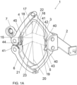
- FIG.1A shows a perspective view of remote center joint 1 in a partially extended position.
- Remote center joint 1 is configured to rotate terminal segment 7 relative to base segment 2 along imaginary axis 15.
- Remote center joint 1 comprises first segment 3 rotatably coupled to base segment 2 along first axis 16.
- Second segment 4 is rotatably coupled to first segment 3 about second axis 17 which intersects first axis 16 at first point 22.
- Second segment 4 is rotatably coupled to terminal segment 7 about third axis 18 which intersects first point 22.
- Third segment 5 is rotatably coupled to base segment 2 about fourth axis 19 parallel to first axis 16.
- Fourth segment 6 is rotatably coupled to third segment 5 about fifth axis 20 which intersects fourth axis 19 at second point 23.
- Fourth segment 6 is rotatably coupled to terminal segment 7 along sixth axis 21 which intersects second point 23.
- Imaginary axis 15 of rotation of terminal segment 7 relative to base segment 2 is a line connecting first point 22 and second point 23.
- Third segment 5 is geared to first segment 3 and fourth segment 6 is geared to second segment At least a portion of a weight, force, or torque applied to terminal segment 7 is transferred by remote center joint 1 to base segment 2.
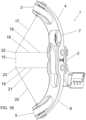
- FIG.1B shows a side view of remote center joint 1. It can be seen that imaginary axis 15 is substantially separated from the hardware profile and does not interest any segment of remote center joint. In other embodiments, imaginary axis 15 does not pass through any mechanical joint. This is in opposition to a real axis which is formed by two or more links and crosses through the hardware of those links, such as first axis 16 formed between base segment 2 and first segment 3. This allows for remote center joint 1 to be placed outside of an object while rotating along an axis that passes through that object. Additionally, remote center joint 1 creates imaginary axis 15 through only rotational joints, as opposed to creating an axis through a curved track and carriage. Rotational joints are simpler to add bearing surface to and seal, increasing the robustness of remote center joint. Additionally, the collapsed configuration of remote center joint as seen in FIG. 2 is much smaller than what would be possible with a curved track and carriage.
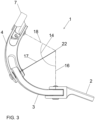
- FIG.2 and FIG.3 show a top view of remote center joint 1.
- first point 22 is coincident with second point 23 and imaginary axis 15 is perpendicular to the page.
- first axis 16 overlaps and hides fourth axis 19
- second axis 17 overlaps and hides fifth axis 20
- third axis 18 overlaps and hides sixth axis 21. It can be seen that first point 22, and thus imaginary axis 15 is substantially separated from the hardware profile. This allows for remote center joint 1 to be placed to the side of an object while rotating along an axis that passes through that object.
- remote center joint 1 is in a flexed position, forming a small joint rotation angle 14 between first axis 16 and third axis 18 about first point 22.
- Joint rotation angle 14 may similarly be defined as the angle between base segment 2 and terminal segment 7 about first point 22.
- a collapsing motion is defined as motion of terminal segment 7 relative to base segment 2 that results in a reduction of joint rotation angle 14.
- An extension motion is defined as motion of terminal segment 7 relative to base segment 2 that results in an increase of joint rotation angle 14.
- remote center joint 1 is in an extend position, forming a large joint rotation angle 14 compared to FIG.2 .
- remote center joint 1 is capable of moving around an object while maintaining imaginary axis 15 passing through the object.
- terminal segment 7 rotates relative to base segment 2 through the intermediate segments and axes without terminal segment 7 being directly coupled to base segment 2.
- Rotation of terminal segment 7 about imaginary axis 15 is not generated by a single joint, but instead is generated by the collective six joints forming first axis 16, second axis 17, third axis 18, fourth axis 19, fifth axis 20, and sixth axis 21.
- terminal segment 7 has only one degree of freedom and is thus not able to translate or rotate in directions other than about imaginary axis 15 due to forces that may be applied to any segment of remote center joint 1. This allows for controlled and predictable motion of terminal segment 7 relative to base segment 2.
- Passive motion of remote center joint 1 may be achieved through forces applied to terminal segment 7 about imaginary axis 15 while base segment 2 remains fixed. Forces applied to terminal segment 7 not creating a movement about imaginary axis 15 will be transferred to base segment 2 without affecting motion of remote center joint 1.
- forces from a rotary or linear actuator either active or passive, may be applied between any two segments of remote center joint 1 to control motion between terminal segment 7 and base segment 2.
- the actuator may be mounted directly onto remote center joint 1, or forces from an externally mounted actuator may be transferred to remote center joint 1 through a cable or cable and pulley system.
- FIG.4 shows a top view of first segment 3 with first axis 16 and second axis 17 converging at first point 22.
- Arc angle 35 is defined as the angle between first axis 16 and second axis 17.
- First distance 36 is the measure between first point 22 and first segment 3 along first axis 16.
- Second distance 37 is the measure between first point 22 and first segment 3 along second axis 17.
- first distance 36 of first segment is different than second distance 37 of first segment.
- first distance 36 of first segment is the same as second distance 37 of first segment.
- First distance 36 and second distance 37 may be utilized to change the position of first point 22 or to alter the profile of remote center joint 1.
- first segment 3 may be of any shape to create first axis 16 and second axis 17.
- first segment 3 has a single bent profile, however first segment 3 may have a curved profile 34 as shown in FIG.3 or a double bent profile 38 as show FIG.9 , among many others.
- Each segment may be of any shape as long as it comprises two intersecting axes of rotation when coupled to neighboring segments.
- first distance 36 corresponds to the distance along first axis 16, third axis 18, fourth axis 19 or sixth axis 21 connecting to base segment 2 or terminal segment 7 as applicable.
- second distance 37 corresponds to the distance along second axis 17 or fifth axis 20 as applicable.
- arc angle 35 of first segment 3, second segment 4, third segment 5, and fourth segment 6 defines the range of motion of terminal segment 7 relative to base segment 2.
- the range of motion of remote center joint 1 is the lesser of arc angle 35 of first segment 3 added to arc angle 35 of second segment 4 compared to arc angle 35 of third segment 5 added to arc angle 35 of fourth segment 6.
- arc angle 35 of first segment 3, second segment 4, third segment 5, and fourth segment 6 are equal. This allows the segments of remote center joint 1 to move symmetrically as shown in FIG.1 , FIG.2 , and FIG. 3 .
- arc angle 35 of first segment 3 is equal to arc angle 35 of third segment 5 and arc angle 35 of second segment 4 is equal to arc angle 35 of fourth segment 6 while the arc angle of first segment 3 is not equal to the arc angle of second segment 4.
- This causes symmetric motion between first segment 3 and third segment 5, and symmetric motion between second segment 4 and fourth segment 6, but asymmetric motion between first segment 3 and second segment 4 as shown in FIG. 5 .
- the segments with (reduced) arc angle 35 will rotate about base segment 2 or terminal segment 7 to a greater degree than the segments with (increased) arc angle 35. This changes the profile of remote center joint 1 throughout the range of motion of terminal segment 7 relative to base segment 2.
- arc angle 35 of first segment 3 is equal to arc angle 35 of second segment 4 and arc angle 35 of third segment 5 is equal to arc angle 35 of fourth segment 6 while the arc angle 35 of first segment 3 is not equal to the arc angle 35 of third segment 5.
- the arc angle 35 is different between each of the first segment 3, second segment 4, third segment 5, and fourth segment 6 creating asymmetry of motion between each segment.
- changing the arc angle 35 of various segments may be used to alter the profile, strength, or aesthetic look of remote center joint 1.
- first distance 36 and second distance 37 of first segment 3, second segment 4, third segment 5, and fourth segment 6 defines the distance of imaginary axis 15 from the hardware, the orientation of imaginary axis 15, and the profile of remote center joint 1.
- first distance 36 and second distance 37 of first segment 3 is equal to first distance 36 and second distance 37 of third segment 5 and first distance 36 and second distance 37 of second segment 4 is equal to first distance 36 and second distance 37 of fourth segment 6.
- first distance 36 of first segment 3 is different than first distance 36 of third segment 5 and first distance 36 of second segment 4 is different than first distance 36 of fourth segment 6.
- second distance 37 of first segment 3 is different than second distance 37 of third segment 5 and second distance 37 of second segment 4 is different than second distance 37 of fourth segment 6. This effect, not shown, creates an asymmetry in profile between the first segment 3 and second segment 4 compared to the third segment 5 and fourth segment 6.
- first distance 36 and second distance 37 of first segment 3 is the same as first distance 36 and second distance 37 of second segment 4
- first distance 36 and second distance 37 of third segment 5 is the same as first distance 36 and second distance 37 of fourth segment 6.
- This configuration is shown in FIG. 1 , FIG.2 and FIG.3 such that first segment 3 and second segment 4 may be joined by a double supported clevis joint.
- terminal segment 7 will contact base segment 2 in a fully flexed position as the segments are not configured to overlap.
- first distance 36 and second distance 37 of first segment 3 is different than first distance 36 and second distance 37 of second segment 4
- first distance 36 and second distance 37 of third segment 5 is different than first distance 36 and second distance 37 of fourth segment 6.
- first distance 36 of any segment will affect how far base segment 2 overlaps terminal segment 7 at the fully flexed position
- second distance 37 of any segment will affect the overlap between segments, specifically the overlap between first segment 3 and second segment 4 along second axis 17, or the overlap between third segment 5 and fourth segment 6 along fifth axis 20.
- Each segment may have varying the first distance 36 or second distance 37 depending on the mechanical connection in order to align their respective axes to first point 22 or second point 23.
- first distance 36 and second distance 37 of the first segment 3, second segment 4, third segment 5, and fourth segment 6 are defined such that imaginary axis 15 is perpendicular to the first axis 16.
- gearing between first segment 3 and third segment 5 is a 1:1 ratio. In other embodiments the gearing between second segment 4 and fourth segment 6 is a 1:1 ratio. In the primary embodiment the gearing between segments occurs through gear teeth integrated into each segment. In other embodiments, separate gears may be attached to each segment to accomplish controlled geared motion between segments. Still in other embodiments, a high friction coating may be sufficient to gear two segments together.
- two segments of remote center joint 1 may be configured to hard stop against each other to limit the range of motion of terminal segment 7 relative to base segment 2.
- Hard stopping motion of remote center joint 1 at an extended position may be utilized to limit the range of motion of remote center joint 1, or to prevent remote center joint 1 from entering a position after which it becomes difficult to re-collapse the joint.
- hard stopping motion of remote center joint 1 at a flexed position may be utilized to limit the range of motion.
- Remote center joint 1 may further comprise a hard stop spring, such as a spring plunger, coupled to any of the segments and configured to selectively contact another segment in order to bias remote center joint 1 away from the hard stop position.
- FIG.6 shows a perspective view of remote center joint 1 in a fully extended position where at least one extension hard stop 40 limits further extension motion.
- both first segment 3 and third segment 5 include extension hard stop 40.
- extension hard stop 40 of first segment 3 contacts extension hard stop 40 of third segment 5
- both first segment 3 and third segment 5 are prevented from further rotation about first axis 16 and fourth axis 19 respectively, thus preventing further extension motion of terminal segment 7 relative to base segment 2.
- hard stops may be placed between any set of two segments to prevent rotation corresponding to collapsing or extending motion of terminal segment 7 relative to base segment 2.
- one of the segments comprises first extension hard stop 40 and another of the segments comprises second extension hard stop 40, wherein at a fully extended position, first extension hard stop 40 and second extension hard stop 40 contact each other to prevent remote center joint 1 from increasing joint rotation angle 14.
- remote center joint 1 further comprises first magnet 42 coupled to first extension hard stop 40 and second magnet 43 coupled to second extension hard stop 40, wherein first magnet 42 and second magnet 43 are configured to repel first extension hard stop 40 from second extension hard stop 40.
- remote center joint 1 further comprises first magnet 42 coupled to first extension hard stop 40 and second magnet 43 coupled to second extension hard stop 40, wherein first magnet 42 and second magnet 43 are configured to attract first extension hard stop 40 to second extension hard stop 40.
- remote center joint 1 further comprises first magnet 42 coupled to any of the segments, and second magnet 43 coupled to any other segment, wherein first magnet 42 and second magnet 43 are configured to bias remote center joint away from an extended hard stop position.
- first magnet 42 and second magnet 43 are configured to bias remote center joint 1 into an extended hard stop position.
- first magnet 42 is coupled to first segment 3, and second magnet 43 is coupled to third segment 5.
- First magnet 42 and second magnet 43 are configured to repel each other to bias the rotation of first segment 3 and third segment 5 in a direction that corresponds to a reduction in joint rotation angle 14 of terminal segment 7 relative to base segment 2. In this configuration the force between first magnet 42 and second magnet 43 is greatest at the fully extended position and reduces as remote center joint 1 moves away from this position.
- a spring such as a spring plunger
- first magnet 42 or second magnet 43 An opposite result may be achieved by reversing the polarity of either first magnet 42 or second magnet 43 so that they attract each other, resulting in a bias of remote center joint 1 towards the fully extended position.
- first magnet 42 and second magnet 43 An equivalent function may be achieved between any two segments of remote center joint 1, with the polarity of first magnet 42 and second magnet 43 impacting whether remote center joint 1 is biased towards or repelled from any position of terminal segment 7 relative to base segment 2, most notably for the fully extended and fully flexed positions.
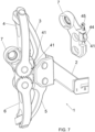
- FIG.7 shows remote center joint 1 in a fully flexed position where at least one flexion hard stop 41 prevents further collapsing motion.
- both first segment 3 and terminal segment 7 include the at least one flexion hard stop 41.
- first segment 3 is prevented from further rotation about first axis 16, thus preventing further collapsing motion of terminal segment 7 relative to base segment 2.
- hard stops may be placed between any set of two segments to prevent rotation corresponding to collapsing or extending motion of terminal segment 7 relative to base segment 2.
- one of the segments comprises a first flexion hard stop 41 and another of the segments comprises a second flexion hard stop 41, wherein at a fully flexed position, the first flexion hard stop 41 and the second flexion hard stop 41 contact each other to prevent remote center joint 1 from decreasing joint rotation angle 14.
- remote center joint 1 further comprises first magnet 42 coupled to first flexion hard stop 41 and stow magnet 44 coupled to second flexion hard stop 41, wherein first magnet 42 and stow magnet 44 are configured to attract first flexion hard stop 41 to second flexion hard stop 41.
- remote center joint 1 further comprises first magnet 42 coupled to any of the segments, and stow magnet 44 coupled to any other segment, wherein first magnet 42 and stow magnet 44 are configured to bias remote center joint 1 into a collapsed hard stop position. Holding remote center joint 1 in a flexed position may be utilized to store the mechanism in a low-profile manner when not in use.
- first magnet 42 is configured to attract stow magnet 44 in order to bias and hold remote center joint 1 in a flexed position.
- remote center joint 1 may further comprise stow switch 45 configured to move stow magnet 44 between a first position and a second position.
- stow magnet 44 When stow magnet 44 is in the first position it comes into contact with first magnet 42 when remote center joint 1 is in a fully flexed position, thus applying a force to hold remote center joint 1 in a fully flexed position.
- stow magnet 44 When stow magnet 44 is in the second position it does not come into contact with first magnet 42 when remote center joint 1 is in a fully flexed position and does not apply a force to hold remote center joint 1 against flexion hard stop 41.
- first magnet 42 is coupled to first segment 3 and stow magnet 44 is moveably coupled to terminal segment 7. It may be understood by one skilled in the art that the first magnet 42 and stow magnet 44 may be placed between any two segments to accomplish the same function as described above.
- remote center joint 1 further comprises a stow mechanism configured to hold remote center joint 1 in a collapsed configuration when not in use.
- a stow mechanism configured to hold remote center joint 1 in a collapsed configuration when not in use.
- Many types of mechanism may be used between any two segments to hold remote center joint 1 in place. Examples include hook and latch, male/female connectors, or an over the center toggle mechanism, among others.
- remote center joint 1 further comprises a spring 82 configured to act between at least two segments to bias the motion of terminal segment 7 relative to base segment 2.
- Spring 82 may be selected from a list including torsion spring, compression spring, gas spring, leaf spring, elastic band, or other common resilient element known to those skilled in the art.
- spring 82 is configured to bias the motion of terminal segment 7 relative to base segment 2 throughout the range of motion of remote center joint 1.
- Spring 82 may be configured to bias remote center joint 1 in an extending or collapsing direction. When spring 82 is configured to bias remote center joint 1 in a collapsing direction it may fulfill a function similar to the stow mechanism described above.
- spring 82 is configured to bias terminal segment 7 in a collapsing direction relative to base segment 2 only at the extreme extended range of motion of remote center joint 1. In other embodiments, spring 82 is configured to bias terminal segment 7 in an extending direction relative to base segment 2 only at the extreme collapsed range of motion of remote center joint 1.
- each segment may be composed of one or more links.
- each segment comprises a single link arranged so that each joint is double supported.
- some segments may comprise two links arranged in parallel so that each joint is double supported.
- each segment may comprise a single link arranged so that each joint is single supported.
- Each arrangement may be utilized for one or more segments to optimize remote center joint 1 for strength, range of motion, profile, or other common characteristics.
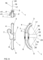
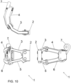
- FIG.9 and FIG.10 show an embodiment of remote center joint 1 wherein the segments are configured so that in the fully collapsed configuration first axis 16 and third axis 18 become approximately coincident. This allows remote center joint 1 to maximize its range of motion and minimize its profile when stowed.
- first segment 3 and third segment 5 are comprised of single linkages
- second segment 4 and fourth segment 6 are comprised of at least two linkages that overlap first segment 3 and third segment 5 while each joint remains double supported.
- FIG. 9 shows remote center joint 1 in a fully flexed position
- FIG. 10 shows remote center joint 1 in an extended position.
- FIG.11 shows an embodiment where two of remote center joint 1 are connected in series in order to maximize the range of motion of a second terminal segment 13 relative to base segment 2 or to minimize profile of the mechanism.
- remote center joint 1 further comprises second base segment 8, fifth segment 9, sixth segment 10, seventh segment 11, eighth segment 12, and second terminal segment 13.
- Second base segment 8 is coupled to terminal segment 7.
- Fifth segment 9 is rotatably coupled to second base segment 8 about seventh axis 25.
- Sixth segment 10 is rotatably coupled to fifth segment 9 about eighth axis 26 that intersects seventh axis 25 at third point 31.
- Second terminal segment 13 is rotatably coupled to sixth segment 10 about ninth axis 27 that intersects third point 31.
- Seventh segment 11 is rotatably coupled to second base segment 8 along tenth axis 28 that is parallel to seventh axis 25 and seventh segment 11 is geared to fifth segment 9.
- Eighth segment 12 is rotatably coupled to seventh segment 11 along eleventh axis 29 that intersects tenth axis 28 at fourth point 32.
- Eighth segment 12 is rotatably coupled to second terminal segment 13 along twelfth axis 30 that intersects fourth point 32 and eighth segment 12 is geared to sixth segment 10.
- Second terminal segment 13 is configured to rotate relative to second base segment 8 about second imaginary axis 33 passing between third point 31 and fourth point 32.
- second segment 4 is geared to fifth segment 9 in a 1:1 ratio to create symmetrical motion between the first remote center joint 1 and the second remote center joint 1.
- fourth segment 6 is geared to seventh segment 11 to create symmetrical motion between first remote center joint 1 and second remote center joint 1.
- first remote center joint 1 may be connected in series in a similar manner to accomplish a given range of motion, loading, profile, or other mechanical requirement.
- linkages of the various remote center joint 1 connected in series may have varying radius, arc angle, or flat sections to vary the location of the multiple imaginary axes or the relative motion of the various segments.
- remote center joint 1 may be used as part of shoulder supporting exoskeleton 60.
- Shoulder supporting exoskeleton 60 may also be referred to as arm supporting exoskeleton 60.
- remote center joint 1 is used to provide motion between torso frame 61 coupled to person's torso 92 and arm segment 70 coupled to person's upper arm 94.
- arm segment 70 is a shoulder supporting actuator configured to at least partially support the gravitational effects due to the weight of the arm about the shoulder joint.
- the motion provided by remote center joint 1 as a part of shoulder supporting exoskeleton 60 corresponds to relatively horizontal motions of upper arm 94 of person 90 while arm segment 70 provides motion for or applies a supportive force to relatively vertical motions of upper arm 94 of person 90.
- imaginary axis 15 created by remote center joint 1 passes approximately through the shoulder joint of person 90 while the hardware remains behind or to the side of the body of person 90. This allows arm segment 70 to move relative to torso frame 61 about an axis that approximately coincides with the shoulder joint of person 90 to provide a natural range of motion and minimize relative motion between shoulder supporting exoskeleton 60 and upper arm 94 of person 90 or torso 92 of person 90.
- Approximately through the shoulder joint of person 90 may mean that an axis crosses through the body of the person near the shoulder joint, scapula, or upper arm. Additionally, this configuration allows for all needed hardware to be placed behind or to the side of person 90, without any hardware being located above the shoulder of person 90 or next to a head 91 of person 90.
- the passive motion of remote center joint 1 is controlled by forces from upper arm 94 of person 90 being transferred through arm segment 70 to terminal segment 7 while base segment 2 is fixed to torso frame 61 which is in turn fixed to torso 92 of person 90.
- remote center joint 1 Supportive forces and torques that are applied to upper arm 94 of person 90 from the arm segment 70 are transferred through remote center joint 1 to torso frame 61, which in turn applies the forces and torques to torso 92 of person 90 and hips 93 of person 90.
- multiples of remote center joint 1 may be used as part of shoulder supporting exoskeleton 60.
- shoulder supporting exoskeleton 60 comprises a torso frame 61, a left remote center joint 1 coupled to torso frame 61, a left arm segment 70 coupled to left remote center joint 1, a right remote center joint 1 coupled to torso frame 61, and right arm segment 70 coupled to right remote center joint 1, wherein torso frame 61 is configured to be coupled to torso 92 of person 90, left arm segment 70 is configured to be coupled to upper arm 94 of person 90 on the left side, and right arm segment 70 is configured to be coupled to upper arm 94 of person 90 on the right side.
- FIG. 13 shows a rear view of remote center joint 1 as part of shoulder supporting exoskeleton 60.
- Remote center joint 1 is configured to rotate terminal segment 7, coupled to upper arm 94 of person 90, relative to base segment 2, coupled to torso 92 of person 90, along imaginary axis 15 passing through the body of person 90.
- Remote center joint 1 comprises first segment 3 rotatably coupled to base segment 2 along first axis 16.
- Second segment 4 is rotatably coupled to first segment 3 about second axis 17 which intersects first axis 16 at first point 22.
- Second segment 4 is rotatably coupled to terminal segment 7 about third axis 18 which intersects first point 22.
- Third segment 5 is rotatably coupled to base segment 2 about fourth axis 19 parallel to first axis 16.
- Third segment 5 is geared to the first segment 3.
- Fourth segment 6 is rotatably coupled to third segment 5 about fifth axis 20 which intersects fourth axis 19 at second point 23.
- Fourth segment 6 is rotatably coupled to terminal segment 7 along sixth axis 21 which intersects second point 23.
- Fourth segment 6 is geared to second segment 4.
- Imaginary axis 15 of rotation of terminal segment 7 relative to base segment 2 is a line connecting first point 22 and second point 23.
- remote center joint 1 is configured to provide horizontal shoulder motion for shoulder supporting exoskeleton 60 wherein base segment 2 is coupled to torso frame 61 of shoulder supporting exoskeleton 60 and terminal segment 7 is coupled to arm segment 70 of shoulder supporting exoskeleton 60.
- remote center joint 1 provides motion along imaginary axis 15 substantially parallel to gravity line 89.
- remote center joint 1 transfers a weight of the arm segment 70 to the torso frame 61 without affecting motion of terminal segment 7 relative to base segment 2.
- remote center joint 1 accommodates for a horizontal motion of the upper arm 94 of person 90 between arm segment 70 and torso frame 61 when the arm supporting exoskeleton 60 is worn by the person 90.
- remote center joint 1 when person 90 is standing upright, as a part of shoulder supporting exoskeleton 60 remote center joint 1 provides motion along imaginary axis 15 skew to gravity line 89 to bias the motion of upper arm 94 of person 90 relative to torso 92 of person 90.
- torso frame 61 further comprises shoulder straps 67 that at least partially encircle a person's s torso 92, and belt 66 that at least partially encircles hips 93 of person 90 to couple shoulder supporting exoskeleton 60 to person 90.
- Remote center joint 1 may further comprise anchor strap 68 coupled to base segment 2 at its first end and configured to couple to shoulder strap 67 from its second end. Anchor strap 68 may be tightened to better secure remote center joint 1 to person 90.
- anchor strap 68 may be coupled to base segment 2 from both ends, and be configured to at least partially encircle persons shoulder, upper arm 94 of person 90, or torso 92 of person 90.
- Torso frame 61 may further comprise lower spine 63 and upper spine 62. To adjust the position of remote center joint 1 relative to belt 66, the location of upper spine 62 may be adjusted and held in place relative to lower spine 63 along the major axis of lower spine 63. This adjustment may be used to adjust the exoskeletons to persons of different height in order to align support axis 71 of arm segment 70 with persons shoulder joint.
- the shoulder joint of person 90 may refer to any area around the shoulder including but not limited to the glenohumeral joint, scapula, humerus, and clavicle.
- torso frame 61 further comprises hip frame 64 coupled to both ends of belt 66 from its distal sides and to lower spine 63 from its center. Hip frame 64 may be configured to transfer forces from torso frame 61 to hips 93 of person 90.
- Torso frame 61 may further comprise spine mount 65 located substantially behind torso 92 of person 90.
- remote center joint 1 is adjustably coupled to spine mount 65 along an axis perpendicular to the major axis of upper spine 62 or lower spine 63.
- Remote center joint 1 may be moved and fixed in place relative to spine mount 65 in order to adjust for the size of person 90 to better align imaginary axis 15 of rotation with the persons shoulder joint.
- remote center joint 1 may be rotationally coupled to torso frame 61 about an axis substantially parallel to imaginary axis 15 created between first point 22 and second point 23. This rotational coupling may occur between base segment 2 and spine mount 65, or base segment 2 may comprise two separate segments capable of rotation relative to each other.
- a rotational coupling between remote center joint 1 and torso frame 61 may be used to extend the range of motion of arm segment 70 relative to torso frame 61.
- remote center joint 1 may be prismatically coupled to torso frame 61 along a direction perpendicular to imaginary axis 15 created between first point 22 and second point 23.
- a prismatic coupling between remote center joint 1 and torso frame 61 may be used to extend the range of motion of arm segment 70 relative to torso frame 61 or to dynamically adjust the alignment of imaginary axis 15 created between first point 22 and second point 23 with the shoulder joint of person 90.
- remote center joint 1 may be coupled to torso frame 61 with a resilient member configured to deform under load and return to its original position when the load is removed.
- the resilient member may be configured to increase the range of motion between arm segment 70 and torso frame 61.
- remote center joint 1 may be rotationally coupled to arm segment 70. This may occur through a rotational coupling between terminal segment 7 and arm segment 70, or terminal segment 7 may comprise two independent segments capable of rotating relative to each other.
- a rotational coupling between remote center joint 1 and arm segment 70 may be used to extend the range of motion of arm segment 70 relative to torso frame 61.
- rotational couplings between remote center joint 1 and torso frame 61 or arm segment 70 may comprise a spring or magnets to bias motion or hard stops to limit motion as described in regards to the motion of the remote center joint above.
- arm segment 70 comprises proximal segment 72 coupled to terminal segment 7 of remote center joint 1, distal segment 73 rotatably coupled to proximal segment 72 about support axis 71, and arm brace 74 coupled to distal segment 73.
- arm segment 70 comprises distal segment 73 configured to rotate relative to terminal segment 7 about support axis 71 orthogonal to the imaginary axis 15, wherein the support axis 71 crosses approximately through the shoulder joint of the person 90, and torque generator coupled to the distal segment 73 configured to apply a torque about the support axis 71 such that the distal segment 73 applies a force to the person's arm.
- arm segment 70 further comprises proximal segment 72 configured to be coupled to terminal segment 7, and distal segment 73 configured to rotate relative to proximal segment 72 about support axis 71 that crosses approximately through the shoulder joint of person 90 orthogonal to imaginary axis 15, wherein distal segment 73 is configured to attach to the arm of person 90, and torque generator coupled to proximal segment 72 from its first end and to distal segment 73 from its second end, the torque generator configured to apply a torque about support axis 71 such that distal segment 73 applies a force to the person's arm to at least partially support the weight of the person's arm.
- a torque generator may include a motor, spring, pneumatic, hydraulic or other type of torque or force creating actuator.
- Torque generator is attached to distal segment 73 from its first end and may be attached to terminal segment 7 or proximal segment 72 from its second end.
- torque generator remotely actuates distal segment 73 about support axis 71 and it attached to distal segment 73 from its first end and to any other component of remote center joint 1 or torso frame 61 from its second end, the forces being transferred to distal segment 73 through a Bowden cable or similar device.
- arm segment 70 is configured to create a torque between proximal segment 72 and distal segment 73 about support axis 71 in order to at least partially support the weight of upper arm 94 of person 90.
- This torque is applied to upper arm 94 of person 90 by arm brace 74, and reaction forces and torques are applied to remote center joint 1 through proximal segment 72.
- Remote center joint 1 transfers vertical forces from arm segment 70 to torso frame 61 which is configured to apply the loads to the hips of person 90.
- Horizontal components of torques from arm segment 70 in turn cause terminal segment 7 to rotate relative to base segment 2 about imaginary axis 15.
- arm segment 70 is configured to apply a torque to arm of person 90 about support axis 71 orthogonal to imaginary axis 15, wherein reaction forces from the torque that do not create a moment about imaginary axis 15 are transferred through remote center joint 1 to torso frame 61 without affecting motion of terminal segment 7 relative to base segment 2.
- support axis 71 is orthogonal to imaginary axis 15 created between first point 22 and second point 23.
- remote center joint 1 maintains support axis 71 passing approximately through persons shoulder joint.
- FIG. 13 and FIG. 14 a top view and back view of person 90 can be seen where persons left arm is oriented to persons side and persons right arm is oriented in front of person 90. It can be seen that when upper arm 94 of person 90 is oriented to the side of person 90, remote center joint 1 moves into a flexed position, as with persons left arm.
- remote center joint 1 moves into an extended position, as with persons right arm. Remote center joint 1 moves to allow arm segment 70 to move in unison with upper arm 94 of person 90 while torso frame 61 remains fixed to torso 92 of person 90.
- arm brace 74 is adjustably coupled to distal segment 73 to adjust the position of arm brace 74 relative to support axis 71 in order to adjust for the length of upper arm 94 of person 90.
- Arm brace 74 may be attached to upper arm 94 of person 90 through an arm strap.
- the orientation of proximal segment 72 can be adjusted relative to remote center joint 1 about an axis parallel to support axis 71 to adjust the support provided by arm segment 70 to person 90.
- the orientation of proximal segment 72 can be adjusted relative to remote center joint 1 about an axis orthogonal to imaginary axis 15 connecting first point 22 and second point 23 to adjust the support provided by arm segment 70 to person 90.
- arm segment 70 is rotatably coupled to remote center joint 1 about an axis parallel to imaginary axis 15 connecting first point 22 and second point 23 to increase the range of motion of arm segment 70 relative to torso frame 61.
- remote center joint 1 may be used as part of neck supporting exoskeleton 80.
- Neck supporting exoskeleton 80 may be used to at least partially support the weight of the head 91 of person 90 as it moves relative to torso 92 of person 90.
- Neck supporting exoskeleton 80 may further comprise torso frame 61 coupled to remote center joint 1 and configured to couple to torso 92 of person 90, and head pillow 81 coupled to remote center joint 1 and configured to contact the head 91 of person 90.
- remote center joint 1 may be configured to create imaginary axis 15 between first point 22 and second point 23 that passes approximately through persons neck.
- remote center joint 1 moves head pillow 81 relative to torso frame 61 about an axis substantially aligned with persons biological spine to prevent relative motion between head pillow 81 and the head 91 of person 90 to reduce discomfort due to chafing.
- FIG. 14 it can be seen that person's head 91 is rotated backwards relative to torso 92 of person 90, as if person 90 was looking upwards, forcing remote center joint 1 into a flexed position.
- imaginary axis 15 between first point 22 and second point 23 passes through persons neck.
- FIG. 15 it can be seen that person's head 91 is rotated forwards relative to FIG. 14 relative to torso 92 of person 90, as if person 90 was looking forward, forcing remote center joint 1 into an extended position.
- imaginary axis 15 between first point 22 and second point 23 remains passing through persons neck.
- Base segment 2 may be coupled to torso frame 61 which is coupled to torso 92 of person 90.
- upper spine 62 may be coupled to torso 92 of person 90 in a manner equivalent to that discussed above for shoulder supporting exoskeleton 60.
- Terminal segment 7 may be coupled to head pillow 81 configured to contact the head 91 of person 90 and apply a supportive force.
- remote center joint 1 may further comprise spring 82 coupled between at least two segments.
- Spring 82 may be configured to bias remote center joint 1 into an extended position.
- spring 82 causes remote center joint 1 to resist the motion of head pillow 81 relative to torso frame 61 to at least partially support the weight of the head 91 of person 90.
- spring 82 causes remote center joint 1 to assist the motion of head pillow 81 relative to torso frame 61 to at least partially support the weight of the head 91 of person 90.
- remote center joint 1 may be configured to support sideways or forward rotation of the head 91 of person 90 relative to torso 92 of person 90 instead of rearwards motion.
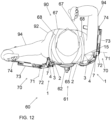
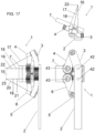
- FIG. 16 and FIG. 17 shows an embodiment of remote center joint 1 configured to accommodate bi-directional spinal twisting motion of torso 92 of person 90 relative to hips 93 of person 90.
- This may be used as a part of shoulder supporting exoskeleton 60, neck supporting exoskeleton 80, or any other type of wearable device such as a back-supporting exoskeleton, backpack, load carriage device, etc.
- remote center joint 1 is configured to create imaginary axis 15 between first point 22 and second point 23 passing through persons spine and oriented along the length of persons spine, parallel to gravity line 89 when person 90 is standing upright.
- base segment 2 is fixed relative to persons lower torso and terminal segment 7 is fixed relative to persons upper torso.
- terminal segment 7 tracks persons upper torso while base segment 2 remains fixed with persons lower torso.
- Persons upper torso may indicate motion of the rib cage, chest, shoulders, neck, or head.
- Persons lower torso may indicate motion of the pelvis or lumbar spine.
- remote center joint 1 When persons spine is in a neutral position, remote center joint 1 may be biased into a flexed position as shown in FIG. 16 .
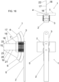
- remote center joint 1 When persons spine is twisted to the right or the left, remote center joint 1 may be biased into an extended position as shown in FIG. 17 . While accommodating for twisting motion of persons pine, remote center joint 1 may transfer forces and toques between terminal segment 7 and base segment 2.
- each segment of remote center joint 1 may consist of one link, with the joints between them arranged in a single supported fashion. This allows each link to overlap with the connected linkages so that remote center joint 1 may extend in two directions about imaginary axis 15 between first point 22 and second point 23.
- first axis 16 aligns with third axis 18 and fourth axis 19 aligns with sixth axis 21 as shown in FIG. 16 a singularity occurs where first segment 3 can rotate relative to third segment 5 without any motion between base segment 2 and terminal segment 7. To avoid this singularity as shown in FIG.
- remote center joint 1 may further comprise first magnet 42 coupled to any of the segments, and second magnet 43 coupled to any other segment, wherein first magnet 42 and second magnet 43 are configured to bias remote center joint 1 away from a position in which first axis 16 aligns with third axis 18 and fourth axis 19 aligns with sixth axis 21.
- First magnet 42 and second magnet 43 in this orientation will toggle remote center joint 1 around this singularity position.
- first magnet 42 is positioned in line with first axis 16 and second magnet 43 is positioned in line with third axis 18, wherein first magnet 42 is configured to repel second magnet 43.
- first magnet 42 and second magnet 43 can similarly be placed in line with fourth axis 19 and sixth axis 21, respectively.
- remote center joint 1 may be use in many applications.
- remote center joint 1 may be used for any other body motion.
- remote center joint 1 may be used to allow an exoskeleton to move with a person during motions including but not limited to internal/external shoulder rotation, internal/external hip rotation, wrist pronation/supination, finger flexion, ankle pronation/supination, spinal flexion, or spinal side bending.
- one of skill in the art may utilize remote center joint 1 for applications in robotics, surgical equipment, tool mounting equipment, or any other device or mechanism where one end must rotate relative to another.
Landscapes
- Health & Medical Sciences (AREA)
- Engineering & Computer Science (AREA)
- Animal Behavior & Ethology (AREA)
- Life Sciences & Earth Sciences (AREA)
- Veterinary Medicine (AREA)
- Public Health (AREA)
- General Health & Medical Sciences (AREA)
- Epidemiology (AREA)
- Pain & Pain Management (AREA)
- Physical Education & Sports Medicine (AREA)
- Rehabilitation Therapy (AREA)
- Mechanical Engineering (AREA)
- Robotics (AREA)
- Orthopedic Medicine & Surgery (AREA)
- Neurology (AREA)
- Biomedical Technology (AREA)
- Manipulator (AREA)
- Toys (AREA)
- Prostheses (AREA)
Claims (15)
- Gelenk mit externem Drehzentrum (1), das Folgendes umfasst:ein Grundsegment (2);ein Endsegment (7);ein erstes Segment (3) und ein drittes Segment (5), die jeweils um parallele Achsen (16, 19) drehbar mit dem Grundsegment gekoppelt sind, wobei das erste Segment und das dritte Segment miteinander verzahnt sind; undein zweites Segment (4) und ein viertes Segment (6), die jeweils um parallele Achsen (18, 21) drehbar mit dem Endsegment gekoppelt sind, wobei das zweite Segment und das vierte Segment miteinander verzahnt sind,wobei das zweite Segment drehbar mit dem ersten Segment gekoppelt ist und das dritte Segment drehbar mit dem vierten Segment gekoppelt ist, so dass das Endsegment relativ zu dem Grundsegment um eine imaginäre Achse (15) drehbar ist, die nicht durch ein mechanisches Gelenk des Gelenks mit externem Drehzentrum verläuft.
- Gelenk mit externem Drehzentrum nach Anspruch 1, wobei die imaginäre Achse (15) parallel zu einer Schwerkraftlinie verläuft, so dass das Gelenk mit externem Drehzentrum ein Gewicht des Endsegments oder ein an diesem befestigtes Gewicht auf das Grundsegment überträgt, ohne die Bewegung des Endsegments relativ zum Grundsegment um die imaginäre Achse zu beeinflussen.
- Gelenk mit externem Drehzentrum nach Anspruch 1, wobei ein erster Segmentbogenwinkel gleich einem dritten Segmentbogenwinkel und ein zweiter Segmentbogenwinkel gleich einem vierten Segmentbogenwinkel ist, so dass ein Übersetzungsverhältnis zwischen dem ersten Segment und dem dritten Segment 1:1 und das Übersetzungsverhältnis zwischen dem zweiten Segment und dem vierten Segment 1:1 ist.
- Gelenk mit externem Drehzentrum nach Anspruch 1, wobei das zweite Segment so konfiguriert ist, dass es das erste Segment überlappt, und das vierte Segment so konfiguriert ist, dass es das dritte Segment überlappt, so dass das Gelenk mit externem Drehzentrum durch eine Position rotieren kann, in der die erste Achse mit der dritten Achse zusammenfällt und die vierte Achse mit der fünften Achse zusammenfällt.
- Gelenk mit externem Drehzentrum nach Anspruch 4, ferner umfassend einen ersten Magneten (42), der mit mindestens einem aus der Gruppe, die gebildet ist von dem Basissegment, dem Endsegment, dem ersten Segment, dem zweiten Segment, dem dritten Segment und dem vierten Segment, gekoppelt ist, und einen zweiten Magneten (43), der mit einem beliebigen anderen aus der Gruppe, die gebildet ist von dem Basissegment, dem Endsegment, dem ersten Segment, dem zweiten Segment, dem dritten Segment und dem vierten Segment, gekoppelt ist, wobei der erste Magnet und der zweite Magnet so konfiguriert sind, dass sie das Gelenk mit externem Drehzentrum von einer Position weg vorspannen, in der die erste Achse mit der dritten Achse und die vierte Achse mit der sechsten Achse fluchtet.
- Gelenk mit externem Drehzentrum nach Anspruch 1, wobei mindestens eines aus der Gruppe, die gebildet ist aus dem Grundsegment, dem Endsegment, dem ersten Segment, dem zweiten Segment, dem dritten Segment und dem vierten Segment, einen ersten Verlängerungsanschlag umfasst und ein anderes aus der Gruppe, die gebildet ist aus dem Grundsegment, dem Endsegment, dem ersten Segment, dem zweiten Segment, dem dritten Segment und dem vierten Segment, einen zweiten Verlängerungsanschlag umfasst, wobei in einer vollständig ausgefahrenen Position der erste Verlängerungsanschlag und der zweite Verlängerungsanschlag einander berühren, um zu verhindern, dass das Gelenk mit externem Drehzentrum einen Gelenkdrehwinkel vergrößert.
- Gelenk mit externem Drehzentrum nach Anspruch 6, das ferner einen ersten Magneten (42), der mit dem ersten Verlängerungsanschlag gekoppelt ist, und einen zweiten Magneten (43), der mit dem zweiten Verlängerungsanschlag gekoppelt ist, umfasst, wobei der erste Magnet und der zweite Magnet so konfiguriert sind, dass sie den ersten Verlängerungsanschlag vom zweiten Verlängerungsanschlag abstoßen.
- Gelenk mit externem Drehzentrum nach Anspruch 1, wobei mindestens eines aus der Gruppe, die gebildet ist von dem Grundsegment, dem Endsegment, dem ersten Segment, dem zweiten Segment, dem dritten Segment und dem vierten Segment. einen ersten Flexionsanschlag und ein anderes aus der Gruppe, die gebildet ist von dem Basissegment, dem Endsegment, dem ersten Segment, dem zweiten Segment, dem dritten Segment und dem vierten Segment, einen zweiten Flexionsanschlag umfasst, wobei in einer vollständig flektierten Position der erste Flexionsanschlag und der zweite Flexionsanschlag einander berühren, um zu verhindern, dass das Gelenk mit externem Drehzentrum einen Gelenkdrehwinkel verringert.
- Gelenk mit externem Drehzentrum nach Anspruch 8, das ferner mit einem ersten Magneten (42), der mit dem ersten Flexionsanschlag gekoppelt ist, und einem Verstaumagneten (44), der mit dem zweiten Flexionsanschlag gekoppelt ist, wobei der erste Magnet und der Verstaumagnet so konfiguriert sind, dass sie den ersten Flexionsanschlag an den zweiten Flexionsanschlag anziehen.
- Gelenk mit externem Drehzentrum nach Anspruch 1, das ferner eine Feder (82) umfasst, die so konfiguriert ist, dass sie zwischen mindestens zwei von dem Grundsegment, dem Endsegment, dem ersten Segment, dem zweiten Segment, dem dritten Segment und dem vierten Segment wirkt, um die Bewegung des Endsegments relativ zu dem Grundsegment vorzuspannen.
- Gelenk mit externem Drehzentrum nach einem der vorstehenden Ansprüche, wobei das Grundsegment so konfiguriert ist, dass es mit einem Exoskelett gekoppelt werden kann, das so konfiguriert ist, dass es von einer Person getragen werden kann, und die imaginäre Achse ungefähr durch den Körper der Person verläuft.
- Gelenk mit externem Drehzentrum nach einem der vorstehenden Ansprüche, wobei das Grundsegment mit einem Torsorahmen (61) eines einen Arm stützenden Exoskeletts gekoppelt ist, wobei der Torsorahmen konfiguriert ist, um mit dem Torso einer Person gekoppelt zu werden, unddas Endsegment so konfiguriert ist, dass es mit einem Armsegment (70) des den Arm stützenden Exoskeletts gekoppelt wird, wobei das Armsegment so konfiguriert ist, dass es mit einem Oberarm der Person gekoppelt wird,wobei, wenn das den Arm stützende Exoskelett von der Person getragen wird, das Gelenk mit externem Drehzentrum das Armsegment relativ zu dem Torsorahmen so dreht, dass die imaginäre Achse ungefähr durch ein Schultergelenk der Person verläuft.
- Gelenk mit externem Drehzentrum nach Anspruch 12, wobei die imaginäre Achse parallel zu einer Schwerkraftlinie verläuft, wenn die Person aufrecht steht, so dass das Gelenk mit externem Drehzentrum eine horizontale Bewegung eines Oberarms der Person zwischen dem Armsegment und dem Torsorahmen zulässt, wenn das den Arm stützende Exoskelett von der Person getragen wird.
- Gelenk mit externem Drehzentrum nach Anspruch 12, wobei das Armsegment so konfiguriert ist, dass es ein Drehmoment auf den Arm der Person um eine zur imaginären Achse orthogonale Stützachse ausübt, wobei Reaktionskräfte aus dem Drehmoment, die kein Moment um die imaginäre Achse erzeugen, durch das Gelenk mit externem Drehzentrum auf den Torsorahmen übertragen werden, ohne die Bewegung des Endsegments relativ zum Grundsegment zu beeinflussen.
- Gelenk mit externem Drehzentrum nach einem der vorstehenden Ansprüche, wobei das erste Segment drehbar mit dem Grundsegment entlang einer ersten Achse (16) gekoppelt ist;das zweite Segment mit dem ersten Segment um eine zweite Achse (17) drehbar gekoppelt ist und mit dem Endsegment um eine dritte Achse (18) drehbar gekoppelt ist, wobei sich die erste Achse, die zweite Achse und die dritte Achse in einem ersten Punkt schneiden;das dritte Segment drehbar mit dem Grundsegment entlang einer vierten Achse parallel zu der ersten Achse gekoppelt ist, unddas vierte Segment drehbar mit dem dritten Segment entlang einer fünften Achse gekoppelt ist und drehbar mit dem Endsegment entlang einer sechsten Achse parallel zur dritten Achse gekoppelt ist, wobei sich die vierte Achse, die fünfte Achse und die sechste Achse in einem zweiten Punkt schneiden,wobei das Gelenk mit externem Drehzentrum das Endsegment relativ zu dem Grundsegment um die imaginäre Achse dreht, die den ersten Punkt und den zweiten Punkt verbindet.
Applications Claiming Priority (2)
| Application Number | Priority Date | Filing Date | Title |
|---|---|---|---|
| US202062991684P | 2020-03-19 | 2020-03-19 | |
| PCT/US2021/023235 WO2021188950A1 (en) | 2020-03-19 | 2021-03-19 | Remote center shoulder joint for shoulder supporting exoskeleton |
Publications (3)
| Publication Number | Publication Date |
|---|---|
| EP4120987A1 EP4120987A1 (de) | 2023-01-25 |
| EP4120987A4 EP4120987A4 (de) | 2024-04-10 |
| EP4120987B1 true EP4120987B1 (de) | 2025-06-25 |
Family
ID=77748675
Family Applications (1)
| Application Number | Title | Priority Date | Filing Date |
|---|---|---|---|
| EP21771767.7A Active EP4120987B1 (de) | 2020-03-19 | 2021-03-19 | Entferntes zentrales schultergelenk für ein schulterstützendes exoskelett |
Country Status (3)
| Country | Link |
|---|---|
| US (1) | US12029699B2 (de) |
| EP (1) | EP4120987B1 (de) |
| WO (1) | WO2021188950A1 (de) |
Families Citing this family (3)
| Publication number | Priority date | Publication date | Assignee | Title |
|---|---|---|---|---|
| EP3959044A1 (de) * | 2019-04-24 | 2022-03-02 | Aalborg Universitet | Kugelmechanismus mit scherengestänge mit steuermitteln |
| EP4120987B1 (de) | 2020-03-19 | 2025-06-25 | suitX, Inc. | Entferntes zentrales schultergelenk für ein schulterstützendes exoskelett |
| CN114366555B (zh) * | 2021-12-31 | 2024-03-15 | 安徽中医药大学 | 一种可穿戴式上肢康复外骨骼机器人 |
Family Cites Families (38)
| Publication number | Priority date | Publication date | Assignee | Title |
|---|---|---|---|---|
| US741382A (en) | 1902-03-24 | 1903-10-13 | Chicago Writing Machine Company | Folding bracket for telephones, &c. |
| USRE32213E (en) | 1974-09-16 | 1986-07-22 | Equipment for use with hand held motion picture cameras | |
| US4298149A (en) | 1978-01-17 | 1981-11-03 | Panavision, Incorporated | Body harness for cinematographer |
| US5111983A (en) | 1986-02-10 | 1992-05-12 | Simmons Elex M | Camera stabilizing device |
| FR2611855B1 (fr) | 1987-03-03 | 1989-07-13 | Spianti Dany | Support d'equipement portatif, notamment de camera |
| US5042763A (en) | 1990-01-05 | 1991-08-27 | Wong William W M | Self-leveling portable camera support apparatus |
| KR100299210B1 (ko) | 1999-03-12 | 2001-09-22 | 박호군 | 인간팔 장착형 힘 재현기능을 갖는 마스터 장치 |
| US6821259B2 (en) | 2001-07-30 | 2004-11-23 | The Nemours Foundation | Orthosis device |
| US6764231B1 (en) | 2003-01-28 | 2004-07-20 | Cory Shubert | Body mounted camera support |
| US7325777B2 (en) | 2005-02-18 | 2008-02-05 | Gordon Daniel Thiessen | Portable articulating tool support |
| WO2006113416A2 (en) | 2005-04-15 | 2006-10-26 | Brown Garrett W | Equipoising support apparatus |
| US7862524B2 (en) * | 2006-03-23 | 2011-01-04 | Carignan Craig R | Portable arm exoskeleton for shoulder rehabilitation |
| EP2185036B1 (de) | 2007-08-30 | 2020-01-15 | BROWN, Garrett W. | Bewegliche stütze für den menschlichen arm |
| AU2009341585B2 (en) | 2008-12-18 | 2015-06-18 | Ekso Bionics, Inc. | Wearable material handling system |
| US8939924B1 (en) * | 2009-05-18 | 2015-01-27 | The Lonnie and Shannon Paulos Trust | Magnet assisted orthotic brace |
| US8585017B2 (en) | 2009-11-30 | 2013-11-19 | Norco Industries, Inc. | Low profile scissor jack |
| KR101572852B1 (ko) | 2010-01-06 | 2015-12-01 | 삼성전자 주식회사 | 팔 보조 장치 |
| WO2011127471A1 (en) | 2010-04-09 | 2011-10-13 | Lockheed Martin Corporation | Portable load lifting system |
| US8591441B2 (en) | 2010-10-22 | 2013-11-26 | Peter M. Bonutti | Shoulder orthosis including flexion/extension device |
| EP2665449B1 (de) | 2011-01-18 | 2017-11-15 | Levitate Technologies, Inc. | Adaptive armstützensysteme und verfahren zu ihrer verwendung |
| US9719633B2 (en) | 2011-05-06 | 2017-08-01 | Garrett W. Brown | Exoskeleton arm interface |
| US9358148B2 (en) * | 2012-04-03 | 2016-06-07 | Annulus, Llc | Dip joint extension splint and methods of using same |
| US9404618B2 (en) | 2012-04-15 | 2016-08-02 | Garrett W. Brown | Lifting extension mount assembly for equipoising arms |
| ITPI20120069A1 (it) | 2012-06-11 | 2013-12-12 | Scuola Superiore S Anna | Esoscheletro per l¿interazione fisica con l¿uomo |
| CA2893555C (en) | 2012-12-11 | 2022-04-26 | Levitate Technologies, Inc. | Adaptive arm support systems and methods for use |
| WO2015058249A1 (en) * | 2013-10-24 | 2015-04-30 | University Of Technology, Sydney | Robotic exoskeleton apparatus |
| US10639785B2 (en) | 2015-05-18 | 2020-05-05 | The Regents Of The University Of California | Variable force generators for arm supporting exoskeletons |
| US9889554B2 (en) | 2015-05-18 | 2018-02-13 | The Regents Of The University Of California | Apparatus for human arm supporting exoskeleton |
| US10391627B2 (en) | 2015-05-18 | 2019-08-27 | The Regents Of The University Of California | Arm supporting exoskeleton with a variable force generator |
| US10569413B2 (en) * | 2015-12-22 | 2020-02-25 | Ekso Bionics, Inc. | Exoskeleton and method of providing an assistive torque to an arm of a wearer |
| TWI600421B (zh) * | 2016-01-05 | 2017-10-01 | 國立成功大學 | 肩關節復健輔具 |
| US10154729B2 (en) * | 2016-05-10 | 2018-12-18 | Knape & Vogt Manufacturing Company | Articulating ergonomic support arm |
| US20190175453A1 (en) | 2016-06-07 | 2019-06-13 | Herobility Ab | A lid for a drinking bottle |
| CN109311167A (zh) * | 2016-06-23 | 2019-02-05 | 国立大学法人香川大学 | 肌力辅助装置 |
| IT201700081177A1 (it) | 2017-07-18 | 2019-01-18 | Iuvo S R L | "Sistema di assistenza agli sforzi da parte di un operatore" |
| US11890751B2 (en) | 2017-10-17 | 2024-02-06 | Aalborg Universitet | Compact spherical 3-DOF mechanism constructed with scissor linkages |
| EP3959044A1 (de) * | 2019-04-24 | 2022-03-02 | Aalborg Universitet | Kugelmechanismus mit scherengestänge mit steuermitteln |
| EP4120987B1 (de) | 2020-03-19 | 2025-06-25 | suitX, Inc. | Entferntes zentrales schultergelenk für ein schulterstützendes exoskelett |
-
2021
- 2021-03-19 EP EP21771767.7A patent/EP4120987B1/de active Active
- 2021-03-19 US US17/206,814 patent/US12029699B2/en active Active
- 2021-03-19 WO PCT/US2021/023235 patent/WO2021188950A1/en not_active Ceased
Also Published As
| Publication number | Publication date |
|---|---|
| US12029699B2 (en) | 2024-07-09 |
| US20210290469A1 (en) | 2021-09-23 |
| EP4120987A1 (de) | 2023-01-25 |
| EP4120987A4 (de) | 2024-04-10 |
| WO2021188950A1 (en) | 2021-09-23 |
Similar Documents
| Publication | Publication Date | Title |
|---|---|---|
| EP4120987B1 (de) | Entferntes zentrales schultergelenk für ein schulterstützendes exoskelett | |
| EP3529015B1 (de) | Kraftausgleichsstütze | |
| US11540969B2 (en) | Ergonomic exoskeleton system for the upper limb | |
| KR102603041B1 (ko) | 착용식 근력 보조 장치 | |
| US11160716B2 (en) | Exoskeleton structure | |
| US10441492B2 (en) | Power transmission apparatus having two belts | |
| US11648169B2 (en) | Wearable apparatus for assisting muscular strength | |
| CN110539289A (zh) | 一种助力外骨骼三自由度对心髋关节机构 | |
| US20240408742A1 (en) | Exoskeletons Comprising Flexible Mechanisms | |
| EP2981240B1 (de) | Mechanische verbindung | |
| KR102681476B1 (ko) | 착용식 근력 보조 장치 | |
| US20100280423A1 (en) | Muscle force assisting device (as amended) | |
| KR102676812B1 (ko) | 상완 근력 보조 장치 | |
| US11376148B2 (en) | Combined structure of wearable apparatus | |
| CN114080207B (zh) | 未充分驱动肩外骨骼远端关节及传递约束反应装置 | |
| US11883956B2 (en) | Wearable gravity compensation apparatus capable of multiple degrees of freedom of movement | |
| KR102792280B1 (ko) | 관절장치 | |
| KR20250152162A (ko) | 관절장치 | |
| WO2025253349A1 (en) | Kinematics for the compensation of an extremity load and exoskeleton that uses such kinematics | |
| KR20240046723A (ko) | 가요성 외골격 프레임과 팔 지지 시스템 및 이를 사용하는 방법 |
Legal Events
| Date | Code | Title | Description |
|---|---|---|---|
| STAA | Information on the status of an ep patent application or granted ep patent |
Free format text: STATUS: THE INTERNATIONAL PUBLICATION HAS BEEN MADE |
|
| PUAI | Public reference made under article 153(3) epc to a published international application that has entered the european phase |
Free format text: ORIGINAL CODE: 0009012 |
|
| STAA | Information on the status of an ep patent application or granted ep patent |
Free format text: STATUS: REQUEST FOR EXAMINATION WAS MADE |
|
| 17P | Request for examination filed |
Effective date: 20221017 |
|
| AK | Designated contracting states |
Kind code of ref document: A1 Designated state(s): AL AT BE BG CH CY CZ DE DK EE ES FI FR GB GR HR HU IE IS IT LI LT LU LV MC MK MT NL NO PL PT RO RS SE SI SK SM TR |
|
| DAV | Request for validation of the european patent (deleted) | ||
| DAX | Request for extension of the european patent (deleted) | ||
| A4 | Supplementary search report drawn up and despatched |
Effective date: 20240311 |
|
| RIC1 | Information provided on ipc code assigned before grant |
Ipc: A61F 2/76 20060101ALI20240304BHEP Ipc: A61F 2/54 20060101ALI20240304BHEP Ipc: B25J 17/02 20060101ALI20240304BHEP Ipc: A61H 1/02 20060101AFI20240304BHEP |
|
| GRAP | Despatch of communication of intention to grant a patent |
Free format text: ORIGINAL CODE: EPIDOSNIGR1 |
|
| STAA | Information on the status of an ep patent application or granted ep patent |
Free format text: STATUS: GRANT OF PATENT IS INTENDED |
|
| INTG | Intention to grant announced |
Effective date: 20241105 |
|
| GRAJ | Information related to disapproval of communication of intention to grant by the applicant or resumption of examination proceedings by the epo deleted |
Free format text: ORIGINAL CODE: EPIDOSDIGR1 |
|
| STAA | Information on the status of an ep patent application or granted ep patent |
Free format text: STATUS: REQUEST FOR EXAMINATION WAS MADE |
|
| GRAP | Despatch of communication of intention to grant a patent |
Free format text: ORIGINAL CODE: EPIDOSNIGR1 |
|
| STAA | Information on the status of an ep patent application or granted ep patent |
Free format text: STATUS: GRANT OF PATENT IS INTENDED |
|
| INTC | Intention to grant announced (deleted) | ||
| INTG | Intention to grant announced |
Effective date: 20250212 |
|
| GRAS | Grant fee paid |
Free format text: ORIGINAL CODE: EPIDOSNIGR3 |
|
| GRAA | (expected) grant |
Free format text: ORIGINAL CODE: 0009210 |
|
| STAA | Information on the status of an ep patent application or granted ep patent |
Free format text: STATUS: THE PATENT HAS BEEN GRANTED |
|
| AK | Designated contracting states |
Kind code of ref document: B1 Designated state(s): AL AT BE BG CH CY CZ DE DK EE ES FI FR GB GR HR HU IE IS IT LI LT LU LV MC MK MT NL NO PL PT RO RS SE SI SK SM TR |
|
| REG | Reference to a national code |
Ref country code: GB Ref legal event code: FG4D |
|
| REG | Reference to a national code |
Ref country code: CH Ref legal event code: EP |
|
| REG | Reference to a national code |
Ref country code: DE Ref legal event code: R096 Ref document number: 602021032934 Country of ref document: DE |
|
| REG | Reference to a national code |
Ref country code: CH Ref legal event code: EP |
|
| REG | Reference to a national code |
Ref country code: IE Ref legal event code: FG4D |
|
| PG25 | Lapsed in a contracting state [announced via postgrant information from national office to epo] |
Ref country code: FI Free format text: LAPSE BECAUSE OF FAILURE TO SUBMIT A TRANSLATION OF THE DESCRIPTION OR TO PAY THE FEE WITHIN THE PRESCRIBED TIME-LIMIT Effective date: 20250625 |
|
| REG | Reference to a national code |
Ref country code: LT Ref legal event code: MG9D |
|
| PG25 | Lapsed in a contracting state [announced via postgrant information from national office to epo] |
Ref country code: NO Free format text: LAPSE BECAUSE OF FAILURE TO SUBMIT A TRANSLATION OF THE DESCRIPTION OR TO PAY THE FEE WITHIN THE PRESCRIBED TIME-LIMIT Effective date: 20250925 Ref country code: GR Free format text: LAPSE BECAUSE OF FAILURE TO SUBMIT A TRANSLATION OF THE DESCRIPTION OR TO PAY THE FEE WITHIN THE PRESCRIBED TIME-LIMIT Effective date: 20250926 |
|
| PG25 | Lapsed in a contracting state [announced via postgrant information from national office to epo] |
Ref country code: BG Free format text: LAPSE BECAUSE OF FAILURE TO SUBMIT A TRANSLATION OF THE DESCRIPTION OR TO PAY THE FEE WITHIN THE PRESCRIBED TIME-LIMIT Effective date: 20250625 |
|
| PG25 | Lapsed in a contracting state [announced via postgrant information from national office to epo] |
Ref country code: HR Free format text: LAPSE BECAUSE OF FAILURE TO SUBMIT A TRANSLATION OF THE DESCRIPTION OR TO PAY THE FEE WITHIN THE PRESCRIBED TIME-LIMIT Effective date: 20250625 |
|
| PG25 | Lapsed in a contracting state [announced via postgrant information from national office to epo] |
Ref country code: RS Free format text: LAPSE BECAUSE OF FAILURE TO SUBMIT A TRANSLATION OF THE DESCRIPTION OR TO PAY THE FEE WITHIN THE PRESCRIBED TIME-LIMIT Effective date: 20250925 |
|
| PG25 | Lapsed in a contracting state [announced via postgrant information from national office to epo] |
Ref country code: LV Free format text: LAPSE BECAUSE OF FAILURE TO SUBMIT A TRANSLATION OF THE DESCRIPTION OR TO PAY THE FEE WITHIN THE PRESCRIBED TIME-LIMIT Effective date: 20250625 |
|
| REG | Reference to a national code |
Ref country code: NL Ref legal event code: MP Effective date: 20250625 |
|
| PG25 | Lapsed in a contracting state [announced via postgrant information from national office to epo] |
Ref country code: NL Free format text: LAPSE BECAUSE OF FAILURE TO SUBMIT A TRANSLATION OF THE DESCRIPTION OR TO PAY THE FEE WITHIN THE PRESCRIBED TIME-LIMIT Effective date: 20250625 |
|
| PG25 | Lapsed in a contracting state [announced via postgrant information from national office to epo] |
Ref country code: PT Free format text: LAPSE BECAUSE OF FAILURE TO SUBMIT A TRANSLATION OF THE DESCRIPTION OR TO PAY THE FEE WITHIN THE PRESCRIBED TIME-LIMIT Effective date: 20251027 |
|
| REG | Reference to a national code |
Ref country code: AT Ref legal event code: MK05 Ref document number: 1805716 Country of ref document: AT Kind code of ref document: T Effective date: 20250625 |