EP4120939B1 - Dispositif de coupe d'implant à double tige - Google Patents
Dispositif de coupe d'implant à double tige Download PDFInfo
- Publication number
- EP4120939B1 EP4120939B1 EP21739468.3A EP21739468A EP4120939B1 EP 4120939 B1 EP4120939 B1 EP 4120939B1 EP 21739468 A EP21739468 A EP 21739468A EP 4120939 B1 EP4120939 B1 EP 4120939B1
- Authority
- EP
- European Patent Office
- Prior art keywords
- implant
- cutter
- coupled
- lead screw
- coupler
- Prior art date
- Legal status (The legal status is an assumption and is not a legal conclusion. Google has not performed a legal analysis and makes no representation as to the accuracy of the status listed.)
- Active
Links
Images







Classifications
-
- A—HUMAN NECESSITIES
- A61—MEDICAL OR VETERINARY SCIENCE; HYGIENE
- A61B—DIAGNOSIS; SURGERY; IDENTIFICATION
- A61B17/00—Surgical instruments, devices or methods
- A61B17/56—Surgical instruments or methods for treatment of bones or joints; Devices specially adapted therefor
- A61B17/58—Surgical instruments or methods for treatment of bones or joints; Devices specially adapted therefor for osteosynthesis, e.g. bone plates, screws or setting implements
- A61B17/88—Osteosynthesis instruments; Methods or means for implanting or extracting internal or external fixation devices
- A61B17/8863—Apparatus for shaping or cutting osteosynthesis equipment by medical personnel
-
- A—HUMAN NECESSITIES
- A61—MEDICAL OR VETERINARY SCIENCE; HYGIENE
- A61B—DIAGNOSIS; SURGERY; IDENTIFICATION
- A61B17/00—Surgical instruments, devices or methods
- A61B17/56—Surgical instruments or methods for treatment of bones or joints; Devices specially adapted therefor
- A61B17/58—Surgical instruments or methods for treatment of bones or joints; Devices specially adapted therefor for osteosynthesis, e.g. bone plates, screws or setting implements
- A61B17/68—Internal fixation devices, including fasteners and spinal fixators, even if a part thereof projects from the skin
- A61B17/70—Spinal positioners or stabilisers, e.g. stabilisers comprising fluid filler in an implant
- A61B17/7074—Tools specially adapted for spinal fixation operations other than for bone removal or filler handling
- A61B17/7076—Tools specially adapted for spinal fixation operations other than for bone removal or filler handling for driving, positioning or assembling spinal clamps or bone anchors specially adapted for spinal fixation
- A61B17/7082—Tools specially adapted for spinal fixation operations other than for bone removal or filler handling for driving, positioning or assembling spinal clamps or bone anchors specially adapted for spinal fixation for driving, i.e. rotating, screws or screw parts specially adapted for spinal fixation, e.g. for driving polyaxial or tulip-headed screws
-
- A—HUMAN NECESSITIES
- A61—MEDICAL OR VETERINARY SCIENCE; HYGIENE
- A61B—DIAGNOSIS; SURGERY; IDENTIFICATION
- A61B17/00—Surgical instruments, devices or methods
- A61B17/16—Instruments for performing osteoclasis; Drills or chisels for bones; Trepans
- A61B17/1613—Component parts
- A61B17/1615—Drill bits, i.e. rotating tools extending from a handpiece to contact the worked material
-
- A—HUMAN NECESSITIES
- A61—MEDICAL OR VETERINARY SCIENCE; HYGIENE
- A61B—DIAGNOSIS; SURGERY; IDENTIFICATION
- A61B17/00—Surgical instruments, devices or methods
- A61B17/16—Instruments for performing osteoclasis; Drills or chisels for bones; Trepans
- A61B17/1613—Component parts
- A61B17/1622—Drill handpieces
- A61B17/1624—Drive mechanisms therefor
-
- A—HUMAN NECESSITIES
- A61—MEDICAL OR VETERINARY SCIENCE; HYGIENE
- A61B—DIAGNOSIS; SURGERY; IDENTIFICATION
- A61B17/00—Surgical instruments, devices or methods
- A61B17/16—Instruments for performing osteoclasis; Drills or chisels for bones; Trepans
- A61B17/1613—Component parts
- A61B17/1633—Sleeves, i.e. non-rotating parts surrounding the bit shaft, e.g. the sleeve forming a single unit with the bit shaft
-
- A—HUMAN NECESSITIES
- A61—MEDICAL OR VETERINARY SCIENCE; HYGIENE
- A61B—DIAGNOSIS; SURGERY; IDENTIFICATION
- A61B17/00—Surgical instruments, devices or methods
- A61B17/16—Instruments for performing osteoclasis; Drills or chisels for bones; Trepans
- A61B17/1662—Instruments for performing osteoclasis; Drills or chisels for bones; Trepans for particular parts of the body
- A61B17/1671—Instruments for performing osteoclasis; Drills or chisels for bones; Trepans for particular parts of the body for the spine
-
- A—HUMAN NECESSITIES
- A61—MEDICAL OR VETERINARY SCIENCE; HYGIENE
- A61B—DIAGNOSIS; SURGERY; IDENTIFICATION
- A61B17/00—Surgical instruments, devices or methods
- A61B17/16—Instruments for performing osteoclasis; Drills or chisels for bones; Trepans
- A61B17/17—Guides or aligning means for drills, mills, pins or wires
- A61B17/1739—Guides or aligning means for drills, mills, pins or wires specially adapted for particular parts of the body
- A61B17/1757—Guides or aligning means for drills, mills, pins or wires specially adapted for particular parts of the body for the spine
-
- A—HUMAN NECESSITIES
- A61—MEDICAL OR VETERINARY SCIENCE; HYGIENE
- A61B—DIAGNOSIS; SURGERY; IDENTIFICATION
- A61B17/00—Surgical instruments, devices or methods
- A61B2017/00477—Coupling
-
- A—HUMAN NECESSITIES
- A61—MEDICAL OR VETERINARY SCIENCE; HYGIENE
- A61B—DIAGNOSIS; SURGERY; IDENTIFICATION
- A61B17/00—Surgical instruments, devices or methods
- A61B17/16—Instruments for performing osteoclasis; Drills or chisels for bones; Trepans
- A61B2017/1602—Mills
Definitions
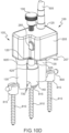
- the cutter 100 may be used to cut/mill spine rods, including, for example, a spine rod 800 affixed to a spine 805 of a patient using spine rod screws 810 having proximally attached tulips 815 (see FIGS. 1 and 10A through 10D ).
- the cutter 100 may be employed, for example, to cut implanted spine rods of varying lengths and diameters (e.g., 2, 4, 6, 8, 10 mm, etc.), as well as those affixed to a spine using structures other than screws 810 and those constructed from various materials, such as, for example, stainless steel, titanium, or cobalt chrome.
- cutter 100 is described herein and shown in the Figures as operable to cut spine rods (such as spine rod 800), it should be appreciated that the cutter 100 and other embodiments contemplated by the subject disclosure may be used to cut/mill other types of implants, and that various embodiments of the subject disclosure are not intended to be limited for use with any particular size, type or category of implant(s).
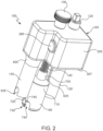
- the cutter 100 includes a gearbox 105, primary and secondary milling bits 110, 110', and a shaft e.g., a threaded lead screw 120 operatively coupled to and extending through the gearbox 105, an input coupling 125 (which e.g., may include a Hudson connector or similar connector for coupling to a driving source) coupled rigidly to the proximal end of the primary milling bit 110, a knob 130 coupled to the proximal end of the lead screw 120, chip collectors 135, 135' coupled to the distal end of the gearbox 105 and respectively circumscribing the primary and secondary milling bits 110, 110', and an implant coupler 140 coupled to the distal end of the lead screw 120 and guided for longitudinal translation by the chip collectors 135, 135', e.g., via guide rails 625, 625'.
- a shaft e.g., a threaded lead screw 120 operatively coupled to and extending through the gearbox 105
- an input coupling 125 which
- the primary milling bit, the secondary milling bit and the lead screw are spaced apart along a substantially linear path, and a longitudinal axis of the primary milling bit and a longitudinal axis of the secondary milling bit are substantially parallel to a longitudinal axis of the lead screw.
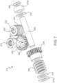
- the primary and secondary milling bits 110, 110' respectively include distal cutting ends 305, 305' for cutting implants e.g., the spine rod 800, and proximal drive ends 310, 310' with respective drive grooves 315, 315' for operatively coupling to the gearbox 105.
- the cutting ends 305, 305' include notched or rounded edges 325, 325' to reduce chipping and spiral flutes 320, 320' for transporting chips and other fragments cut/milled from the spine rod 800 proximally toward center regions 330, 330' of the bits 110, 110'.
- At least the cutting ends 305, 305' of the primary and secondary milling bits 110, 110' are made from tungsten carbide, though it should be appreciated that other portions of the milling bits 110, 110' may also be made of tungsten carbide, or that any or all portions thereof may be constructed using alternative materials. It should also be appreciated that the cutting ends 305, 305' may be center or edge cutting and/or or have rounded edges 325, 325', and that various exemplary embodiments of the subject disclosure are not intended to be limited to any particular type of cutting end or manner of cutting the spine rod 800 or other implant.
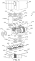
- the gearbox 105 includes a housing 205 with a distal plate 207 enclosing translation and milling drive assemblies 210, 215 operable respectively to translate the gearbox 105 distally with respect to the lead screw 120 or along a longitudinal extent of the lead screw and to drive the secondary milling bit 110' in response to a rotational driving force applied to the input coupling 125, as well as various washers 270 and bushings 275a, 275b, 275c, 275d, 275e and 275f to protect the various components of the drive assemblies 210, 215 from wear and to properly position, align and space the components within the housing 205.
- the driving force is supplied e.g., by a drill 500 with a flexible drive shaft 505, though it should be appreciated that the rotational driving force may be applied to the input coupling 125 in other ways, such as, for example, via a rigid drive shaft, and that various exemplary embodiments of the subject disclosure are not intended to be limited to any particular manner of applying a driving force to the input coupling 125.
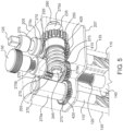
- the translation drive assembly 210 includes a first worm screw 220 having a longitudinal bore 225 receiving the proximal drive end 310 of the primary milling bit 110 and a longitudinally extending drive rib 230 engaging the drive groove 315 of the primary milling bit 110, a first worm gear 235 operatively coupled to the first worm screw 220, a shaft 245 extending longitudinally through the first worm gear 235 and bounded at one end by an end cap 280 and circlip (not shown) inside the housing 205 and on the other end by an alignment receptacle 285 ( FIG.
- a second worm screw 250 disposed rotatably on and circumscribing the shaft 245 and coupled rigidly to the first worm gear 235, a second worm gear 255 operatively coupled to the second worm screw 250 and having a hexagonal socket 260 and a longitudinal through bore 265 circumscribing the lead screw 120, and a hexagonal lead nut 272 positioned within the hexagonal socket 260 and threadedly engaged with the lead screw 120.
- the chip collectors 135, 135' circumscribe the primary and secondary milling bits 110, 110' and respectively include proximal funnel-shaped ends 605, 605' coupled to the distal plate 207 of the housing 205, generally cylindrical body portions 610 having internal chip collection cavities 620 in communication with the milling bits 110, 110' and outer surfaces provided with longitudinally extending guide rails 625, 625', longitudinal bores 630 extending from the distal bottoms of chip collection cavities 620 to the distal ends of the body portions 610, 610', and cutouts 635 shaped to receive the spine rod 800 and facing transversely to and intersecting the longitudinal bores 630 at the distal ends of the body portions 610, 610'.
- the internal diameters of bores 630 at the distal ends of the chip collectors are equal to or slightly larger than the external diameters of the primary and secondary milling bits 110, 110' to effectively retain or seal the chip collection cavities 620 and prevent chips and other fragments removed from the spine rod 800 from escaping the cavities 620.
- the cutouts 635 are U-shaped to receive the spine rod 800, though it should be appreciated that the cutouts 635 may be shaped differently to receive other types of implants.
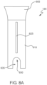
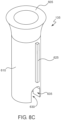
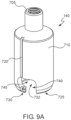
- the implant coupler 140 includes a proximal threaded receptacle 705 coupled to the distal end of the lead screw 120 and a generally cylindrical coupling body 710 having an outer surface provided with longitudinally extending grooves 720, 720' respectively and slidably engaging with the guide rails 625, 625' of the chip collectors 135, 135' and a distal end 725 provided with a socket 730 e.g., a helicopter socket and a hollow receptacle 732 shaped e.g., to receive a tulip 815 of a spine rod screw 810 for properly orientating and aligning the cutter 100 during a cutting/milling operation.
- a socket 730 e.g., a helicopter socket and a hollow receptacle 732 shaped e.g., to receive a tulip 815 of a spine rod screw 810 for properly orientating and aligning the cutter 100 during a cutting/milling operation.
- the implant coupler may or may not include a hollow receptacle e.g., the implant coupler may be of smaller diameter or a cylinder having a socket for engaging a rod similar to socket 730. In this alternative embodiment, the coupler does not receive the tulip 815 and engages only with the spine rod 800.
- the socket 730 is shaped to releasably receive the spine rod 800 and includes helicopter cutouts having respective and radially aligned or diametrically opposed receipt channels 740, 740' and locking channels 745, 745'.
- the locking channels 745, 745' are also configured to align planarly with the cutouts 635 of the chip collectors 135, 135' so that the primary and secondary milling bits 110, 110' can properly align with the spine rod 800 during operation of the cutter 100.
- the receipt channels 740, 740' and locking channels 745, 745' may be shaped differently to receive differently shaped rods and other implants.
- the implant coupler 140 may include structures in addition to or in lieu of the socket 730 for releasably receiving the spine rod 800 or other implant.
- a user To operate the cutter 100 to cut/mill the spine rod 800, a user first aligns the cutter 100 (see FIG. 10A ) and engages the hollow receptacle 732 of the implant coupler with a tulip 815 of a spine rod screw 810, while at the same time aligning the receipt channels 740, 740' of the implant coupler 140 with the spine rod 800 (see FIG. 10B ). Once the spine rod 800 is received completely within the receipt channels 740, 740' of the implant coupler 140, the user rotates the cutter 100 counterclockwise (when viewed distally from the proximal side of the cutter 100) to position the spine rod 800 fully within the locking channels (see FIG.
- spur gears 405, 415, 420 may be sized differently and/or include different numbers of teeth, and that the secondary milling bit 110' may rotate at a different speed or in a different rotational direction compared to the primary milling bit 110.
- the clockwise rotation of the hexagonal lead nut 272 causes the lead screw 120 to produce a distal force on the lead nut 272, thereby causing the gearbox 105 (with coupled milling bits 110, 110' and chip collectors 135, 135') to translate distally along the lead screw 120 guided by engagement of the guide rails 625, 625' of the chip collectors 135, 135' with the grooves 720, 720' of the implant coupler 140.
- the device may use a compound gear set instead of worm drive gears.
- the gearbox 105 translates distally until the distal cutting ends 305, 305' of the primary and secondary milling bits 110, 110' contact the spine rod 800, at which point cutting/milling of the spine rod 800 begins.
- the cutouts 635 of the chip collectors 135, 135' engage with the spine rod 800 and help guide the milling bits 110, 110' as they advance therethrough. Chips and other fragments removed from the spine rod 800 are transported proximally by the spiral flutes 320, 320' of the primary and secondary milling bits 110, 110' into the chip collection cavities 620 of the chip collectors 135, 135', where they are deposited and maintained during the cutting/milling operation.
- the primary and secondary milling bits 110, 110' continue to translate distally until they cut through the spine rod 800, at which point the cutting/milling operation ends ( FIG. 10D ) and the cutter 100 is removed from the patient.
- proximal top surfaces of cutouts 635 which engage with the spine rod 800 to prevent the distal center-cutting ends 305, 305' of the primary and secondary milling bits 110, 110' from translating too far distally into the patient.
- the proximal top surfaces of cutouts of the chip collectors prevent further distal penetration of the cutting ends of the primary and secondary milling bits once the spine rod is cut thereby.
- the largest diameter of spine rods is currently 6 mm. Therefore, there will be a hard stop on the travel of the cutters at a distance slightly greater than 6 mm.
- the cylindrical guides concentric to the cutters have a cutout that accepts the spine rod. The furthest travel of the cutters is limited to not extend past these guides.
- the chip collectors 135, 135' are removed from the cutter 100 so that the chips and other fragments cut/milled from the spine rod 800, as well as any chips and fragments remaining in the spiral flutes 320, 320' of the primary and secondary milling bits 110, 110', may be accessed and discarded.
- removal of the chip collectors 135, 135' may be facilitated by first detaching the implant coupler 140 from the cutter 100.
- This may be effectuated by first rotating the knob 130 counterclockwise to retract the distal end of the lead screw 120 from the threaded receptacle 705 of the implant coupler 140 and then sliding the coupler 140 distally to disengage the guide rails 625, 625' of the chip collectors 135, 135' from the grooves 720, 720' of the implant coupler 140.
- the cutter 100 may then be reset to perform a new cutting/milling operation by first reattaching the chip collectors 135, 135' and the implant coupler 140 and then translating the gearbox 105 proximally into its initial position by applying a counterclockwise rotational force to the input coupling 125 manually or by using the drill 500 or other mechanism.
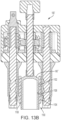
- FIGS. 11 , 12 , 13A and 13B disclose further exemplary embodiments of the subject disclosure, which include a clamping mechanism for applying clamping force to an implant during cutting of the implant.
- the various clamping mechanisms of these embodiments hold the implant firmly and steady in place to prevent chattering of the implant, i.e., resist vibrations of the implant, caused by milling.
- chattering of the implant i.e., resist vibrations of the implant, caused by milling.
- FIGS. 11 , 12 , 13A and 13B only those elements of the implant cutters shown in FIGS. 11 , 12 , 13A and 13B that materially depart in structure and/or function from their counterparts shown in FIGS. 1-10D , or are otherwise necessary for a proper understanding of the subject disclosure, will be described in detail.
- the clamping mechanism 900 comprises an axially extending elongated shaft 902 have threads threadedly engaging the implant coupler e.g., about its proximal end 902a.
- the threaded shaft includes a handle 904 at a proximal end thereof and an implant engageable tip 906 at a distal end thereof operable to clampingly engage the implant, e.g., spine rod 800.
- knob 130' and threaded lead screw 120' may be correspondingly internally threaded to engage with the external threading of the shaft 902. That is the lead screw 120' and/or knob 130' can include a longitudinal through hole having internal threads.
- the knob 130' and the threaded lead screw 120' are provided with smooth-walled internal bores of slightly larger diameter than the diameter of the threaded shaft.
- FIG. 12 there is shown an exemplary embodiment of a clamping mechanism 1000 operatively connected to the implant coupler 140" for applying clamping force to an implant 800 during cutting of the implant.
- the clamping mechanism 1000 comprises a set screw receiver 1002 radially or laterally projecting from the implant coupler 140" and a laterally extending set screw 1004 threadedly engaging the implant coupler at the set screw receiver and operable to clampingly engage the implant.
- the set screw has a socket 1006 or other tool engageable structure that permits the set screw to be advanced into the implant coupler until it firmly engages the implant. Milling of the implant can then be performed with minimal or no vibration of the implant occurring during milling.
- FIGS. 13A and 13B there is shown an exemplary embodiment of a clamping mechanism 1100 operatively connected to the implant coupler 140′′′ for applying clamping force to an unillustrated implant during cutting thereof.
- a circumferential surface of the implant coupler is externally threaded at 1102.
- the clamping mechanism includes a substantially cylindrical sleeve 1104 surrounding the implant coupler and having internal threading 1106 configured to threadedly engage the external threading of the implant coupler.
- the internally threaded sleeve 1104 includes a distal edge 1108 operable to clampingly engage the implant.
- the external surface of the sleeve 1104 can be provided with structure 1110 for enhancing a user's grip when turning the sleeve relative to the implant coupler.
- structure 1110 can include recesses, raised ridges, knurling, and the like.
Landscapes
- Health & Medical Sciences (AREA)
- Surgery (AREA)
- Life Sciences & Earth Sciences (AREA)
- Orthopedic Medicine & Surgery (AREA)
- Medical Informatics (AREA)
- Molecular Biology (AREA)
- Veterinary Medicine (AREA)
- Engineering & Computer Science (AREA)
- Biomedical Technology (AREA)
- Heart & Thoracic Surgery (AREA)
- Public Health (AREA)
- Nuclear Medicine, Radiotherapy & Molecular Imaging (AREA)
- Animal Behavior & Ethology (AREA)
- General Health & Medical Sciences (AREA)
- Neurology (AREA)
- Dentistry (AREA)
- Oral & Maxillofacial Surgery (AREA)
- Surgical Instruments (AREA)
- Dental Prosthetics (AREA)
- Prostheses (AREA)
Claims (14)
- Un outil de coupe (100) pour couper un implant (800), caractérisé par :une boîte de vitesses (105) ;une mèche de fraisage primaire (110), une mèche de fraisage secondaire (110') et une vis mère (120) espacées le long d'un trajet sensiblement linéaire et couplées de manière fonctionnelle à la boîte de vitesses ;un accouplement d'entrée (125) couplé à une mèche de fraisage primaire ; etUn coupleur d'implant (140) couplé à la vis mère, la boîte de vitesses étant conçue pour se déplacer par rapport à la vis mère et entraîner la mèche de fraisage secondaire en réponse à une force de rotation appliquée au couplage d'entrée, la boîte de vitesses comprenant :
Un ensemble d'entraînement en translation (210) conçu pour déplacer la boîte de vitesses par rapport à la vis mère en réponse à la force de rotation appliquée à l'accouplement d'entrée, et un ensemble d'entraînement de fraisage (215) conçu pour entraîner la mèche de fraisage secondaire en réponse à la force de rotation appliquée à l'accouplement d'entrée. - L'outil de coupe selon la revendication 1, dans lequel l'ensemble d'entraînement en translation comprend :une première vis sans fin (220) circonscrivant et couplée à la mèche de fraisage primaire ;un premier engrenage à vis sans fin (235) couplé de manière fonctionnelle à la première vis sans fin ;une seconde vis sans fin (250) couplée rigidement au premier engrenage à vis sans fin ; etun second engrenage à vis sans fin (255) couplé de manière opérationnelle à la seconde vis sans fin, le second engrenage à vis sans fin circonscrivant la vis mère et comportant une douille (260).
- L'outil de coupe selon la revendication 2, dans lequel l'ensemble d'entraînement en translation comprend en outre un écrou (272) dans la douille du second engrenage à vis sans fin et s'engage par filetage dans la vis mère.
- L'outil de coupe selon la revendication 1 ou la revendication 2, dans lequel l'ensemble d'entraînement de fraisage comprend :un premier engrenage droit (405) circonscrivant et couplé rigidement à la mèche de fraisage primaire ;un second engrenage droit (415) couplé de manière opérationnelle au premier engrenage droit ; etun troisième engrenage droit (420) couplé de manière opérationnelle au second engrenage droit circonscrivant et couplé de manière rigide à la mèche de fraisage secondaire.
- L'outil de coupe selon l'une quelconque des revendications précédentes, comprenant en outre des premier et second collecteurs de copeaux (135', 135) couplés à la boîte de vitesses et circonscrivant respectivement les mèches de fraisage primaire et secondaire.
- L'outil de coupe selon la revendication 5, dans laquelle chacun des premier et second collecteurs de copeaux comprend une découpe (635) destinée à recevoir l'implant et une cavité de collecte de copeaux (620) destinée à maintenir les copeaux et les fragments fraisés à l'écart de l'implant, ou dans lequel chacun des premier et second collecteurs de copeaux comprend un rail de guidage longitudinal (625, 625') destiné à s'engager de manière coulissante avec une rainure respective (720, 720') sur le coupleur d'implant.
- L'outil de coupe selon la revendication 6, dans lequel chacun des premier et second collecteurs de copeaux comprend un rail de guidage longitudinal (625, 625') pour s'engager de manière coulissante avec une rainure respective (720, 720') sur le coupleur d'implant.
- L'outil de coupe selon l'une quelconque des revendications précédentes, dans lequel le coupleur d'implant comprend un réceptacle (705) couplé à une extrémité distale de la vis mère et une douille d'hélicoptère (730) structurée pour se coupler de manière amovible à l'implant, ou dans lequel le coupleur d'implant comprend un évidement (732) pour recevoir une tulipe (815) d'une vis (810).
- L'outil de coupe selon l'une quelconque des revendications précédentes, dans lequel chacune des mèches de fraisage primaires et secondaires comprend une extrémité de coupe distale (305, 305') avec des cannelures en spirale (320, 320') pour couper l'implant et une extrémité d'entraînement proximale (310, 310') couplée de manière fonctionnelle à la boîte de vitesses.
- L'outil de coupe selon l'une quelconque des revendications précédentes, dans lequel la mèche de fraisage primaire, la mèche de fraisage secondaire et la vis mère sont espacées le long d'un trajet sensiblement linéaire.
- L'outil de coupe selon l'une quelconque des revendications précédentes, dans lequel le coupleur d'implant est structuré pour se coupler à une tige dorsale (800).
- L'outil de coupe selon l'une quelconque des revendications précédentes, dans lequel l'accouplement d'entrée peut fonctionner pour recevoir une force d'entraînement en rotation.
- L'outil de coupe selon l'une quelconque des revendications précédentes comprenant en outre un mécanisme de serrage (900, 1000, 1100) pour appliquer une force de serrage à un implant pendant la coupe de l'implant.
- L'outil de coupe selon la revendication 13, dans lequel le mécanisme de serrage (900) comprend un arbre s'étendant de manière axiale (902) s'engageant dans le coupleur d'implant, l'arbre comprenant une extrémité proximale et une pointe (906) pouvant s'engager dans l'implant à une extrémité distale de celui-ci, pouvant être utilisées pour engager par serrage l'implant, ou dans lequel le mécanisme de serrage (1000) comprend une vis de réglage (1004) s'étendant à travers le coupleur d'implant, ou dans lequel le mécanisme de serrage (1100) comprend des filetages internes (1106) pouvant être utilisés pour engager par filetage le coupleur d'implant, et un bord distal (1108) pour engager par serrage l'implant.
Applications Claiming Priority (2)
| Application Number | Priority Date | Filing Date | Title |
|---|---|---|---|
| US202063026972P | 2020-05-19 | 2020-05-19 | |
| PCT/US2021/033135 WO2021236754A1 (fr) | 2020-05-19 | 2021-05-19 | Dispositif de coupe d'implant à double tige |
Publications (3)
| Publication Number | Publication Date |
|---|---|
| EP4120939A1 EP4120939A1 (fr) | 2023-01-25 |
| EP4120939B1 true EP4120939B1 (fr) | 2025-07-02 |
| EP4120939C0 EP4120939C0 (fr) | 2025-07-02 |
Family
ID=76829618
Family Applications (1)
| Application Number | Title | Priority Date | Filing Date |
|---|---|---|---|
| EP21739468.3A Active EP4120939B1 (fr) | 2020-05-19 | 2021-05-19 | Dispositif de coupe d'implant à double tige |
Country Status (6)
| Country | Link |
|---|---|
| US (1) | US12256963B2 (fr) |
| EP (1) | EP4120939B1 (fr) |
| JP (1) | JP7388668B2 (fr) |
| CN (1) | CN115515517B (fr) |
| AU (1) | AU2021277283B2 (fr) |
| WO (1) | WO2021236754A1 (fr) |
Families Citing this family (2)
| Publication number | Priority date | Publication date | Assignee | Title |
|---|---|---|---|---|
| US20240325063A1 (en) * | 2023-03-31 | 2024-10-03 | Shukla Medical | Spine rod cutter |
| WO2025064874A1 (fr) * | 2023-09-20 | 2025-03-27 | Paragon 28, Inc. | Foret à angle droit, instrumentation, système et procédés d'utilisation et d'assemblage |
Family Cites Families (11)
| Publication number | Priority date | Publication date | Assignee | Title |
|---|---|---|---|---|
| US5578039A (en) | 1995-02-15 | 1996-11-26 | Smith & Nephew Richards Inc. | Tibial resection instrumentation and surgical method |
| US5988027A (en) * | 1997-05-14 | 1999-11-23 | Lenox - Maclaren | Surgical rod cutter |
| DE102008053566A1 (de) | 2007-11-27 | 2009-06-04 | Bernhard Hildebrandt | System aus Endprothesen und Geräten zur minimal invasiven und zementfreien Implantation von Endoprothesen der Schulter und der Hüfte und der Offset-Verbesserung des Schenkelhalses |
| US8968420B2 (en) * | 2008-04-17 | 2015-03-03 | Warsaw Orthopedic, Inc. | Surgical prosthetic device cutting tool |
| US9427274B1 (en) | 2013-10-17 | 2016-08-30 | Z'egist Solutions, LLC | Surgical cutting system and method |
| WO2016065489A1 (fr) | 2014-10-31 | 2016-05-06 | RIOS Medical AG | Ensemble implant pour l'articulation sacro-iliaque |
| US10070909B2 (en) | 2015-05-27 | 2018-09-11 | Medos International Sàrl | Devices and methods for bending or cutting implants |
| DE102015120725A1 (de) | 2015-11-30 | 2017-06-01 | Aesculap Ag | Medizinisches Schneidinstrument |
| AU2017201327A1 (en) * | 2016-02-29 | 2017-09-14 | Stryker European Holdings I, Llc | Rod cutting debris collector and guide |
| WO2019183491A1 (fr) | 2018-03-22 | 2019-09-26 | Dignity Health | Appareil et dispositif de découpe osseuse pour le retrait de tissu osseux |
| US11950818B2 (en) * | 2019-09-30 | 2024-04-09 | Shukla Medical | Implant cutter |
-
2021
- 2021-05-19 AU AU2021277283A patent/AU2021277283B2/en active Active
- 2021-05-19 JP JP2022561192A patent/JP7388668B2/ja active Active
- 2021-05-19 US US17/324,616 patent/US12256963B2/en active Active
- 2021-05-19 WO PCT/US2021/033135 patent/WO2021236754A1/fr not_active Ceased
- 2021-05-19 CN CN202180029565.0A patent/CN115515517B/zh active Active
- 2021-05-19 EP EP21739468.3A patent/EP4120939B1/fr active Active
Also Published As
| Publication number | Publication date |
|---|---|
| EP4120939A1 (fr) | 2023-01-25 |
| JP2023526170A (ja) | 2023-06-21 |
| US12256963B2 (en) | 2025-03-25 |
| CN115515517B (zh) | 2025-03-28 |
| AU2021277283A1 (en) | 2022-11-03 |
| CN115515517A (zh) | 2022-12-23 |
| US20210361326A1 (en) | 2021-11-25 |
| EP4120939C0 (fr) | 2025-07-02 |
| AU2021277283B2 (en) | 2024-05-02 |
| WO2021236754A1 (fr) | 2021-11-25 |
| JP7388668B2 (ja) | 2023-11-29 |
Similar Documents
| Publication | Publication Date | Title |
|---|---|---|
| US6918914B2 (en) | Minimally invasive adjustable acetubular reamer | |
| EP1567070B1 (fr) | Taraudage a longueur reglable et procede pour percer et tarauder un orifice dans un os | |
| US8523866B2 (en) | Modular tapered hollow reamer for medical applications | |
| CA2791886C (fr) | Outil reglable pour attaches tubulees | |
| US20080300600A1 (en) | Resurfacing reamer with cutting struts | |
| AU2021277283B2 (en) | Dual rod implant cutter | |
| WO2007107842A2 (fr) | Système d'aléseuse guidée pour reformer un os | |
| WO1998035621A9 (fr) | Guide-foret en profondeur reglable | |
| EP3975939B1 (fr) | Dispositif de préparation d'un tibia pour la réception d'un composant d'implant tibial d'une cheville de remplacement | |
| KR20070020018A (ko) | 깊이 조정가능한 드릴 비트 | |
| WO2013154686A1 (fr) | Trépans chirurgicaux | |
| RU2741718C2 (ru) | Хирургическое сверло | |
| US8403931B2 (en) | Modular tapered hollow reamer for medical applications | |
| US10912573B2 (en) | Intramedullary canal reamer | |
| US11083470B2 (en) | Expandable reamer cutting head | |
| US7575432B2 (en) | Torque transmission for a surgical or dental rotating tool | |
| EP4147668A1 (fr) | Kit d'implantation permettant la préparation d'un trou d'implant sur l'os en un seul forage avec un seul ostéotome | |
| EP2945562B1 (fr) | Tige d'un instrument dentaire | |
| US11752012B1 (en) | Arthrodesis surgical apparatus and method | |
| CN216797808U (zh) | 一种可调节的瞄准套管 | |
| US7316690B2 (en) | Angled driver with depth gauge | |
| CN213465207U (zh) | 医用磨钻钻头 |
Legal Events
| Date | Code | Title | Description |
|---|---|---|---|
| STAA | Information on the status of an ep patent application or granted ep patent |
Free format text: STATUS: UNKNOWN |
|
| STAA | Information on the status of an ep patent application or granted ep patent |
Free format text: STATUS: THE INTERNATIONAL PUBLICATION HAS BEEN MADE |
|
| PUAI | Public reference made under article 153(3) epc to a published international application that has entered the european phase |
Free format text: ORIGINAL CODE: 0009012 |
|
| STAA | Information on the status of an ep patent application or granted ep patent |
Free format text: STATUS: REQUEST FOR EXAMINATION WAS MADE |
|
| 17P | Request for examination filed |
Effective date: 20221021 |
|
| AK | Designated contracting states |
Kind code of ref document: A1 Designated state(s): AL AT BE BG CH CY CZ DE DK EE ES FI FR GB GR HR HU IE IS IT LI LT LU LV MC MK MT NL NO PL PT RO RS SE SI SK SM TR |
|
| DAV | Request for validation of the european patent (deleted) | ||
| DAX | Request for extension of the european patent (deleted) | ||
| STAA | Information on the status of an ep patent application or granted ep patent |
Free format text: STATUS: EXAMINATION IS IN PROGRESS |
|
| 17Q | First examination report despatched |
Effective date: 20240604 |
|
| RIN1 | Information on inventor provided before grant (corrected) |
Inventor name: SERVEDIO, BRIAN JOSEPH Inventor name: SWEITZER, ZACHARY, ROBERT |
|
| GRAP | Despatch of communication of intention to grant a patent |
Free format text: ORIGINAL CODE: EPIDOSNIGR1 |
|
| STAA | Information on the status of an ep patent application or granted ep patent |
Free format text: STATUS: GRANT OF PATENT IS INTENDED |
|
| INTG | Intention to grant announced |
Effective date: 20250217 |
|
| GRAS | Grant fee paid |
Free format text: ORIGINAL CODE: EPIDOSNIGR3 |
|
| GRAA | (expected) grant |
Free format text: ORIGINAL CODE: 0009210 |
|
| STAA | Information on the status of an ep patent application or granted ep patent |
Free format text: STATUS: THE PATENT HAS BEEN GRANTED |
|
| AK | Designated contracting states |
Kind code of ref document: B1 Designated state(s): AL AT BE BG CH CY CZ DE DK EE ES FI FR GB GR HR HU IE IS IT LI LT LU LV MC MK MT NL NO PL PT RO RS SE SI SK SM TR |
|
| REG | Reference to a national code |
Ref country code: GB Ref legal event code: FG4D |
|
| REG | Reference to a national code |
Ref country code: CH Ref legal event code: EP |
|
| REG | Reference to a national code |
Ref country code: DE Ref legal event code: R096 Ref document number: 602021033390 Country of ref document: DE |
|
| REG | Reference to a national code |
Ref country code: IE Ref legal event code: FG4D |
|
| U01 | Request for unitary effect filed |
Effective date: 20250722 |
|
| U07 | Unitary effect registered |
Designated state(s): AT BE BG DE DK EE FI FR IT LT LU LV MT NL PT RO SE SI Effective date: 20250729 |
|
| PG25 | Lapsed in a contracting state [announced via postgrant information from national office to epo] |
Ref country code: IS Free format text: LAPSE BECAUSE OF FAILURE TO SUBMIT A TRANSLATION OF THE DESCRIPTION OR TO PAY THE FEE WITHIN THE PRESCRIBED TIME-LIMIT Effective date: 20251102 |
|
| PG25 | Lapsed in a contracting state [announced via postgrant information from national office to epo] |
Ref country code: NO Free format text: LAPSE BECAUSE OF FAILURE TO SUBMIT A TRANSLATION OF THE DESCRIPTION OR TO PAY THE FEE WITHIN THE PRESCRIBED TIME-LIMIT Effective date: 20251002 |
|
| PG25 | Lapsed in a contracting state [announced via postgrant information from national office to epo] |
Ref country code: HR Free format text: LAPSE BECAUSE OF FAILURE TO SUBMIT A TRANSLATION OF THE DESCRIPTION OR TO PAY THE FEE WITHIN THE PRESCRIBED TIME-LIMIT Effective date: 20250702 |
|
| PG25 | Lapsed in a contracting state [announced via postgrant information from national office to epo] |
Ref country code: GR Free format text: LAPSE BECAUSE OF FAILURE TO SUBMIT A TRANSLATION OF THE DESCRIPTION OR TO PAY THE FEE WITHIN THE PRESCRIBED TIME-LIMIT Effective date: 20251003 |
|
| PG25 | Lapsed in a contracting state [announced via postgrant information from national office to epo] |
Ref country code: CZ Free format text: LAPSE BECAUSE OF FAILURE TO SUBMIT A TRANSLATION OF THE DESCRIPTION OR TO PAY THE FEE WITHIN THE PRESCRIBED TIME-LIMIT Effective date: 20250702 |
|
| PG25 | Lapsed in a contracting state [announced via postgrant information from national office to epo] |
Ref country code: PL Free format text: LAPSE BECAUSE OF FAILURE TO SUBMIT A TRANSLATION OF THE DESCRIPTION OR TO PAY THE FEE WITHIN THE PRESCRIBED TIME-LIMIT Effective date: 20250702 |
|
| PG25 | Lapsed in a contracting state [announced via postgrant information from national office to epo] |
Ref country code: RS Free format text: LAPSE BECAUSE OF FAILURE TO SUBMIT A TRANSLATION OF THE DESCRIPTION OR TO PAY THE FEE WITHIN THE PRESCRIBED TIME-LIMIT Effective date: 20251002 |
|
| PG25 | Lapsed in a contracting state [announced via postgrant information from national office to epo] |
Ref country code: ES Free format text: LAPSE BECAUSE OF FAILURE TO SUBMIT A TRANSLATION OF THE DESCRIPTION OR TO PAY THE FEE WITHIN THE PRESCRIBED TIME-LIMIT Effective date: 20250702 |
|
| PG25 | Lapsed in a contracting state [announced via postgrant information from national office to epo] |
Ref country code: SM Free format text: LAPSE BECAUSE OF FAILURE TO SUBMIT A TRANSLATION OF THE DESCRIPTION OR TO PAY THE FEE WITHIN THE PRESCRIBED TIME-LIMIT Effective date: 20250702 |
|
| PG25 | Lapsed in a contracting state [announced via postgrant information from national office to epo] |
Ref country code: SK Free format text: LAPSE BECAUSE OF FAILURE TO SUBMIT A TRANSLATION OF THE DESCRIPTION OR TO PAY THE FEE WITHIN THE PRESCRIBED TIME-LIMIT Effective date: 20250702 |
|
| PLBE | No opposition filed within time limit |
Free format text: ORIGINAL CODE: 0009261 |
|
| STAA | Information on the status of an ep patent application or granted ep patent |
Free format text: STATUS: NO OPPOSITION FILED WITHIN TIME LIMIT |