EP4120571A1 - Hybrid adc circuit and method - Google Patents
Hybrid adc circuit and method Download PDFInfo
- Publication number
- EP4120571A1 EP4120571A1 EP21186151.3A EP21186151A EP4120571A1 EP 4120571 A1 EP4120571 A1 EP 4120571A1 EP 21186151 A EP21186151 A EP 21186151A EP 4120571 A1 EP4120571 A1 EP 4120571A1
- Authority
- EP
- European Patent Office
- Prior art keywords
- signal
- circuit
- filter
- adc
- analog
- Prior art date
- Legal status (The legal status is an assumption and is not a legal conclusion. Google has not performed a legal analysis and makes no representation as to the accuracy of the status listed.)
- Pending
Links
Images


Classifications
-
- H—ELECTRICITY
- H03—ELECTRONIC CIRCUITRY
- H03M—CODING; DECODING; CODE CONVERSION IN GENERAL
- H03M1/00—Analogue/digital conversion; Digital/analogue conversion
- H03M1/12—Analogue/digital converters
- H03M1/14—Conversion in steps with each step involving the same or a different conversion means and delivering more than one bit
- H03M1/16—Conversion in steps with each step involving the same or a different conversion means and delivering more than one bit with scale factor modification, i.e. by changing the amplification between the steps
- H03M1/164—Conversion in steps with each step involving the same or a different conversion means and delivering more than one bit with scale factor modification, i.e. by changing the amplification between the steps the steps being performed sequentially in series-connected stages
-
- H—ELECTRICITY
- H03—ELECTRONIC CIRCUITRY
- H03M—CODING; DECODING; CODE CONVERSION IN GENERAL
- H03M1/00—Analogue/digital conversion; Digital/analogue conversion
- H03M1/001—Analogue/digital/analogue conversion
-
- H—ELECTRICITY
- H03—ELECTRONIC CIRCUITRY
- H03M—CODING; DECODING; CODE CONVERSION IN GENERAL
- H03M1/00—Analogue/digital conversion; Digital/analogue conversion
- H03M1/06—Continuously compensating for, or preventing, undesired influence of physical parameters
- H03M1/0617—Continuously compensating for, or preventing, undesired influence of physical parameters characterised by the use of methods or means not specific to a particular type of detrimental influence
- H03M1/0626—Continuously compensating for, or preventing, undesired influence of physical parameters characterised by the use of methods or means not specific to a particular type of detrimental influence by filtering
- H03M1/0629—Anti-aliasing
-
- H—ELECTRICITY
- H03—ELECTRONIC CIRCUITRY
- H03M—CODING; DECODING; CODE CONVERSION IN GENERAL
- H03M3/00—Conversion of analogue values to or from differential modulation
- H03M3/30—Delta-sigma modulation
- H03M3/322—Continuously compensating for, or preventing, undesired influence of physical parameters
- H03M3/324—Continuously compensating for, or preventing, undesired influence of physical parameters characterised by means or methods for compensating or preventing more than one type of error at a time, e.g. by synchronisation or using a ratiometric arrangement
- H03M3/344—Continuously compensating for, or preventing, undesired influence of physical parameters characterised by means or methods for compensating or preventing more than one type of error at a time, e.g. by synchronisation or using a ratiometric arrangement by filtering other than the noise-shaping inherent to delta-sigma modulators, e.g. anti-aliasing
-
- H—ELECTRICITY
- H03—ELECTRONIC CIRCUITRY
- H03M—CODING; DECODING; CODE CONVERSION IN GENERAL
- H03M3/00—Conversion of analogue values to or from differential modulation
- H03M3/30—Delta-sigma modulation
- H03M3/458—Analogue/digital converters using delta-sigma modulation as an intermediate step
- H03M3/46—Analogue/digital converters using delta-sigma modulation as an intermediate step using a combination of at least one delta-sigma modulator in series with at least one analogue/digital converter of a different type
-
- H—ELECTRICITY
- H03—ELECTRONIC CIRCUITRY
- H03M—CODING; DECODING; CODE CONVERSION IN GENERAL
- H03M1/00—Analogue/digital conversion; Digital/analogue conversion
-
- H—ELECTRICITY
- H03—ELECTRONIC CIRCUITRY
- H03M—CODING; DECODING; CODE CONVERSION IN GENERAL
- H03M1/00—Analogue/digital conversion; Digital/analogue conversion
- H03M1/12—Analogue/digital converters
-
- H—ELECTRICITY
- H03—ELECTRONIC CIRCUITRY
- H03M—CODING; DECODING; CODE CONVERSION IN GENERAL
- H03M3/00—Conversion of analogue values to or from differential modulation
-
- H—ELECTRICITY
- H03—ELECTRONIC CIRCUITRY
- H03M—CODING; DECODING; CODE CONVERSION IN GENERAL
- H03M3/00—Conversion of analogue values to or from differential modulation
- H03M3/30—Delta-sigma modulation
- H03M3/39—Structural details of delta-sigma modulators, e.g. incremental delta-sigma modulators
- H03M3/412—Structural details of delta-sigma modulators, e.g. incremental delta-sigma modulators characterised by the number of quantisers and their type and resolution
- H03M3/422—Structural details of delta-sigma modulators, e.g. incremental delta-sigma modulators characterised by the number of quantisers and their type and resolution having one quantiser only
- H03M3/424—Structural details of delta-sigma modulators, e.g. incremental delta-sigma modulators characterised by the number of quantisers and their type and resolution having one quantiser only the quantiser being a multiple bit one
- H03M3/426—Structural details of delta-sigma modulators, e.g. incremental delta-sigma modulators characterised by the number of quantisers and their type and resolution having one quantiser only the quantiser being a multiple bit one the quantiser being a successive approximation type analogue/digital converter
-
- H—ELECTRICITY
- H03—ELECTRONIC CIRCUITRY
- H03M—CODING; DECODING; CODE CONVERSION IN GENERAL
- H03M3/00—Conversion of analogue values to or from differential modulation
- H03M3/30—Delta-sigma modulation
- H03M3/39—Structural details of delta-sigma modulators, e.g. incremental delta-sigma modulators
- H03M3/436—Structural details of delta-sigma modulators, e.g. incremental delta-sigma modulators characterised by the order of the loop filter, e.g. error feedback type
-
- H—ELECTRICITY
- H03—ELECTRONIC CIRCUITRY
- H03M—CODING; DECODING; CODE CONVERSION IN GENERAL
- H03M3/00—Conversion of analogue values to or from differential modulation
- H03M3/30—Delta-sigma modulation
- H03M3/458—Analogue/digital converters using delta-sigma modulation as an intermediate step
Definitions
- the present disclosure relates to the field of analog to digital converter (ADC) circuits and methods. More specifically, the present disclosure relates to a hybrid ADC circuit for converting an analog input signal into a digital output signal method, and to an automobile radar system comprising such hybrid ADC circuit. Furthermore, the present disclosure relates to a method of converting an analog input signal into a digital output signal.
- ADC analog to digital converter
- Hybrid ADC circuits such as successive approximation register (SAR) assisted continuous-time delta-sigma (CT ⁇ ) analog-to-digital converter (ADC) circuits, have many applications, including car radar products for preventing collisions.
- SAR successive approximation register
- CT ⁇ continuous-time delta-sigma
- ADC analog-to-digital converter
- a hybrid ADC device for converting an analog input signal into a digital output signal.
- the device comprises a first ADC circuit configured to receive the analog input signal and convert it into a first digital signal; a DAC circuit configured to receive the first digital signal and convert it into a first analog signal; a delay circuit configured to delay the analog input signal; a first combiner configured to generate an analog residual signal by subtracting the first analog signal from the delayed analog input signal; a second ADC circuit configured to receive the residual analog signal and convert it into a second digital signal; a filter circuit configured to receive the first digital signal and output a filtered first digital signal, the filter circuit having a transfer function corresponding to a combined transfer function of the DAC circuit and the second ADC circuit; and a second combiner configured to generate the digital output signal by adding the second digital signal and the filtered first digital signal, wherein the first ADC circuit comprises an anti-aliasing filter.
- This aspect is based on the idea that an anti-aliasing filter is embedded into the first ADC circuit of the hybrid ADC device in order to prevent or at least reduce or attenuate aliasing signals (also referred to as "blockers") within the input signal bandwidth.
- aliasing signals also referred to as "blockers”
- the anti-aliasing filter comprises a passive low-pass filter arranged to filter the analog input signal prior to converting the analog input signal into the first digital signal.
- the passive low-pass filter is easy and cheap to implement and provides an effective reduction of the undesirable aliasing effects that occur in prior art circuits.
- the first ADC circuit comprises a CT Sigma-Delta ADC with passive loop filter.
- the anti-aliasing filter is implemented as an integral part (i.e., as the loop filter) of a CT (Continuous-Time) Sigma-Delta ADC.
- the CT Sigma-Delta ADC may be a first order, second order, third order, or even higher order Delta-Sigma modulator.
- the loop filter may be implemented as a cascade of first order filters.
- the passive loop filter comprises an RC filter circuit.
- the passive loop filter comprises a simple analog low-pass filter.
- the delay circuit comprises an all-pass filter.
- the delay circuit serves to assure that the analog input signal is delayed by an amount corresponding to the delay induced by the first ADC circuit and the DAC circuit. Thereby, the first analog signal and the delayed analog input signal are in phase at the first combiner.
- the second ADC circuit comprises a low-pass filter, an amplifier, and a CT Delta-Sigma ADC circuit.
- the second ADC circuit is configured to filter the analog residual signal and amplify the filtered analog residual signal as appropriate before converting it into the second digital signal.
- a method of converting an analog input signal into a digital output signal comprises receiving the analog input signal at a first ADC circuit and converting it into a first digital signal; receiving the first digital signal at a DAC circuit and converting it into a first analog signal; delaying the analog input signal utilizing a delay circuit; generating an analog residual signal by subtracting the first analog signal from the delayed analog input signal in a first combiner; receiving the residual analog signal at a second ADC circuit and converting it into a second digital signal; receiving the first digital signal at a filter circuit and outputting a filtered first digital signal, the filter circuit having a transfer function corresponding to a combined transfer function of the DAC circuit and the second ADC circuit; and generating the digital output signal by adding the second digital signal and the filtered first digital signal in a second combiner, wherein the first ADC circuit comprises an anti-aliasing filter.
- This aspect is essentially based on the same idea as the first aspect discussed above and provides the same and similar advantages in terms of a method.
- the anti-aliasing filter comprises a passive low-pass filter arranged to filter the analog input signal prior to converting the analog input signal into the first digital signal.
- the passive low-pass filter is easy and cheap to implement and provides an effective reduction of the undesirable aliasing effects that occur in prior art circuits.
- the first ADC circuit comprises a CT Sigma-Delta ADC with passive loop filter.
- the anti-aliasing filter is implemented as an integral part (i.e., as the loop filter) of a CT (Continuous-Time) Sigma-Delta ADC.
- the CT Sigma-Delta ADC may be a first order, second order, third order, or even higher order Delta-Sigma modulator.
- the loop filter may be implemented as a cascade of first order filters.
- the passive loop filter comprises an RC filter circuit.
- the passive loop filter comprises a simple analog low-pass filter.
- the delay circuit comprises an all-pass filter.
- the delay circuit serves to assure that the analog input signal is delayed by an amount corresponding to the delay induced by the first ADC circuit and the DAC circuit. Thereby, the first analog signal and the delayed analog input signal are in phase at the first combiner.
- the second ADC circuit comprises a low-pass filter, an amplifier, and a CT Delta-Sigma ADC circuit.
- the second ADC circuit is configured to filter the analog residual signal and amplify the filtered analog residual signal as appropriate before converting it into the second digital signal.
- an automobile radar system comprising the hybrid ADC device according to the first aspect or any of the above embodiments thereof.
- Figure 1 shows a block diagram of a hybrid ADC device 101 according to the prior art.
- the device 101 comprises a 5b-SAR ADC 110 forming a first ADC circuit configured to receive the analog input signal Vin and convert it into a first digital signal Y0.
- the device 101 further comprises a 5b-DAC circuit 120 configured to receive the first digital signal Y0 and convert it into a first analog signal A1.
- the device 101 further comprises an all-pass filter 130 forming delay circuit configured to delay the analog input signal Vin, thereby providing a delayed analog input signal Vind.
- a first combiner 140 is arranged and configured to generate an analog residual signal ⁇ by subtracting the first analog signal A1 from the delayed analog input signal Vind.
- the residual signal ⁇ corresponds to quantization noise, non-linearity and sampling images formed in the first ADC circuit 110.
- the device 101 further comprises a second ADC circuit 150 configured to receive the residual analog signal ⁇ and convert it into a second digital signal Y1.
- the second ADC circuit comprises a low-pass filter 152 for filtering the residual analog signal ⁇ , an amplifier 154 for amplifying the filtered residual analog signal ⁇ , and a CT ⁇ ADC 156 for digitizing the amplified residual analog signal ⁇ , thereby forming the second digital signal Y1.
- a filter circuit 160 is arranged and configured to receive the first digital signal Y0 and to output a filtered first digital signal Y0', the filter circuit having a transfer function H(z) corresponding to a combined transfer function H(s) of the DAC circuit 120 and the second ADC circuit 150.
- the device 101 comprises a second combiner 170 arranged and configured to generate the digital output signal Vout by adding the second digital signal Y1 and the filtered first digital signal Y0', such that the unwanted signal content corresponding to the residual signal ⁇ is cancelled out.
- the first ADC circuit 110, the DAC circuit 120, and the second ADC circuit 150 all have the same sampling frequency Fs.
- the first ADC circuit 110, the DAC circuit 120, and the second ADC circuit 150 may have different sampling frequencies.
- the first ADC circuit 110 and/or the second ADC circuit 150 may run at half the sampling frequency of the DAC circuit 120. This would allow to save some power at the cost of a more complex implementation of the all-pass filter 130.
- the first ADC circuit 110 and/or the second ADC circuit 150 may run at higher sampling frequencies than the DAC circuit 120. Thereby, the latency of the first ADC circuit 110 and/or the second ADC circuit 150 is reduced, and as a result thereof, the implementation of the all-pass filer 130 may be less complex.
- a major disadvantage of the architecture depicted in Fig. 1 is that the SAR ADC 110 aliases blockers located around Fs-Fbw (where Fbw denotes the desired bandwidth) into the input signal bandwidth which in return increases the amplitude of the residue signals ⁇ present at the input of the LPF 152. Since the LPF 152, amplifier 154 and CT ⁇ ADC 156 do not filter the in-band signals, the back end of the ADC must be able to have enough dynamic range to process such aliased blockers.
- the present disclosure provides an improved hybrid ADC device 202 as shown in Figure 2 .
- the first ADC circuit 210 comprises an anti-aliasing filter 214 in front of the SAR-based quantizer 212, and a feedback loop 218 coupled to a combiner 216 in front of the anti-aliasing filter 214.
- the circuit 202 comprises a first ADC circuit 210 with an embedded anti-aliasing filter 214 implemented as a loop filter, preferably a passive low-pass filter. Otherwise, the circuit 202 is similar to circuit 101 shown in Figure 1 and the corresponding description of the further elements and functions is not repeated here.
- summing the filtered first digital signal Y0' and the second digital signal Y1 at the combiner 270 results in cancellation of both aliasing components as well as SAR ADC related errors.
- FIG 3 shows a circuit diagram of a first ADC circuit 310 comprising a passive loop filter 314 according to an exemplary embodiment.
- the circuit 310 may in particular be used as the first ADC circuit 210 in the embodiment shown in Figure 2 .
- the loop filter 314 is a first order passive low-pass filter comprising resistor R1, capacitor C1, and, optionally, capacitor C2.
- the feedback loop 318 comprises a DAC 319.
- the ADC circuit 310 is shown as a first order passive delta-sigma modulator.
- the loop may be implemented as a cascade of passive low-pass filters.
- stabilization networks such as feed-forward coefficients, can also be implemented with passive components.
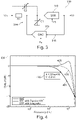
- Figure 4 shows a plot 404 of transfer functions 481, 483, 485 for three different filter configurations.
- Figure 5 shows a plot of corresponding phase responses 591, 593, 595 for the three different filter configurations.
- the transfer function 481 shows the transfer function (STF) of a configuration where a first order anti-aliasing filter with a cut-off frequency of 400MHz (cf. point 482 in Figure 4 ) is arranged in front of the prior art device 101 shown in Figure 1 .
- STF transfer function
- the corresponding phase response 591 is shown in Figure 5 and it appears from point 592 that the first order filter introduces -45° of phase shift at 400MHz.
- the device 202 shown in Figure 2 is represented by the curves 485 and 595.
- the in-band attenuation of the filter is not present anymore and a phase shift of -45° does not occur until 950MHz (cf. point 596 in Figure 5 ).
- the curves 483 and 593 respectively show transfer function and phase response for an implementation with an integrator, as suggested e.g., in US Patent No. 9,614,510 .
- the curves 483 and 593 extend mainly in-between the curves 481, 485 and 591, 595.
- the corresponding implementation is far more complex in comparison to the embedded passive loop filter suggested herein.
- FIG. 6 shows a flow chart 600 of a method of converting an analog input signal into a digital output signal according to an exemplary embodiment.
- the method 600 begins at 610 by receiving the analog input signal Vin at a first ADC circuit 210 and converting it into a first digital signal Y0.
- the first ADC circuit 210 comprises an anti-aliasing filter 214, 314.
- the first digital signal Y0 is received at a DAC circuit 220 and converted into a first analog signal A1.
- the analog input signal Vin is delayed utilizing a delay circuit 230.
- the method continues at 640 by generating an analog residual signal ⁇ by subtracting the first analog signal A1 from the delayed analog input signal in a first combiner 240.
- the residual analog signal ⁇ is received at a second ADC circuit 250 and converted into a second digital signal Y1. Furthermore, at 660, the first digital signal Y0 is received at a filter circuit 260 and a filtered first digital signal Y0' is output.
- the filter circuit 260 has a transfer function H(z) corresponding to a combined transfer function H(s) of the DAC circuit 220 and the second ADC circuit 250. Then, at 670, the digital output signal Vout is generated by adding the second digital signal Y1 and the filtered first digital signal Y0' in a second combiner 270.
- the proposed hybrid ADC circuit 202 is particularly useful in an automobile radar system for collision prevention as it provides a significant increase in useful bandwidth without adding significant complexity, cost, or footprint in comparison to existing systems.
Abstract
Description
- The present disclosure relates to the field of analog to digital converter (ADC) circuits and methods. More specifically, the present disclosure relates to a hybrid ADC circuit for converting an analog input signal into a digital output signal method, and to an automobile radar system comprising such hybrid ADC circuit. Furthermore, the present disclosure relates to a method of converting an analog input signal into a digital output signal.
- Hybrid ADC circuits, such as successive approximation register (SAR) assisted continuous-time delta-sigma (CTΔΣ) analog-to-digital converter (ADC) circuits, have many applications, including car radar products for preventing collisions. However, with increasing requirements for input signal bandwidth beyond 100MHz, aliasing effects make it difficult to achieve the required power efficiency while effectively utilizing the available supply headroom.
- There may thus be a need for circuits and methods capable of overcoming these drawbacks.
- This need may be met by the subject matter according to the independent claims. Advantageous embodiments of the present disclosure are set forth in the dependent claims.
- According to a first aspect, there is provided a hybrid ADC device for converting an analog input signal into a digital output signal. The device comprises a first ADC circuit configured to receive the analog input signal and convert it into a first digital signal; a DAC circuit configured to receive the first digital signal and convert it into a first analog signal; a delay circuit configured to delay the analog input signal; a first combiner configured to generate an analog residual signal by subtracting the first analog signal from the delayed analog input signal; a second ADC circuit configured to receive the residual analog signal and convert it into a second digital signal; a filter circuit configured to receive the first digital signal and output a filtered first digital signal, the filter circuit having a transfer function corresponding to a combined transfer function of the DAC circuit and the second ADC circuit; and a second combiner configured to generate the digital output signal by adding the second digital signal and the filtered first digital signal, wherein the first ADC circuit comprises an anti-aliasing filter.
- This aspect is based on the idea that an anti-aliasing filter is embedded into the first ADC circuit of the hybrid ADC device in order to prevent or at least reduce or attenuate aliasing signals (also referred to as "blockers") within the input signal bandwidth. Thereby, corresponding increases in amplitude of the analog residual signal are correspondingly prevented (or at least reduced or attenuated).
- According to an embodiment, the anti-aliasing filter comprises a passive low-pass filter arranged to filter the analog input signal prior to converting the analog input signal into the first digital signal.
- The passive low-pass filter is easy and cheap to implement and provides an effective reduction of the undesirable aliasing effects that occur in prior art circuits.
- According to a further embodiment, the first ADC circuit comprises a CT Sigma-Delta ADC with passive loop filter.
- In this embodiment, the anti-aliasing filter is implemented as an integral part (i.e., as the loop filter) of a CT (Continuous-Time) Sigma-Delta ADC. The CT Sigma-Delta ADC may be a first order, second order, third order, or even higher order Delta-Sigma modulator. In case of higher order (i.e., above first order) Delta-Sigma modulators, the loop filter may be implemented as a cascade of first order filters.
- According to a further embodiment, the passive loop filter comprises an RC filter circuit.
- In other words, the passive loop filter comprises a simple analog low-pass filter.
- According to a further embodiment, the delay circuit comprises an all-pass filter.
- The delay circuit serves to assure that the analog input signal is delayed by an amount corresponding to the delay induced by the first ADC circuit and the DAC circuit. Thereby, the first analog signal and the delayed analog input signal are in phase at the first combiner.
- According to a further embodiment, the second ADC circuit comprises a low-pass filter, an amplifier, and a CT Delta-Sigma ADC circuit.
- In other words, the second ADC circuit is configured to filter the analog residual signal and amplify the filtered analog residual signal as appropriate before converting it into the second digital signal.
- According to a second aspect, there is provided a method of converting an analog input signal into a digital output signal. The method comprises receiving the analog input signal at a first ADC circuit and converting it into a first digital signal; receiving the first digital signal at a DAC circuit and converting it into a first analog signal; delaying the analog input signal utilizing a delay circuit; generating an analog residual signal by subtracting the first analog signal from the delayed analog input signal in a first combiner; receiving the residual analog signal at a second ADC circuit and converting it into a second digital signal; receiving the first digital signal at a filter circuit and outputting a filtered first digital signal, the filter circuit having a transfer function corresponding to a combined transfer function of the DAC circuit and the second ADC circuit; and generating the digital output signal by adding the second digital signal and the filtered first digital signal in a second combiner, wherein the first ADC circuit comprises an anti-aliasing filter.
- This aspect is essentially based on the same idea as the first aspect discussed above and provides the same and similar advantages in terms of a method.
- According to a further embodiment, the anti-aliasing filter comprises a passive low-pass filter arranged to filter the analog input signal prior to converting the analog input signal into the first digital signal.
- The passive low-pass filter is easy and cheap to implement and provides an effective reduction of the undesirable aliasing effects that occur in prior art circuits.
- According to a further embodiment, the first ADC circuit comprises a CT Sigma-Delta ADC with passive loop filter.
- In this embodiment, the anti-aliasing filter is implemented as an integral part (i.e., as the loop filter) of a CT (Continuous-Time) Sigma-Delta ADC. The CT Sigma-Delta ADC may be a first order, second order, third order, or even higher order Delta-Sigma modulator. In case of higher order (i.e., above first order) Delta-Sigma modulators, the loop filter may be implemented as a cascade of first order filters.
- According to a further embodiment, the passive loop filter comprises an RC filter circuit.
- In other words, the passive loop filter comprises a simple analog low-pass filter.
- According to a further embodiment, the delay circuit comprises an all-pass filter.
- The delay circuit serves to assure that the analog input signal is delayed by an amount corresponding to the delay induced by the first ADC circuit and the DAC circuit. Thereby, the first analog signal and the delayed analog input signal are in phase at the first combiner.
- According to a further embodiment, the second ADC circuit comprises a low-pass filter, an amplifier, and a CT Delta-Sigma ADC circuit.
- In other words, the second ADC circuit is configured to filter the analog residual signal and amplify the filtered analog residual signal as appropriate before converting it into the second digital signal.
- According to a third aspect, there is provided an automobile radar system comprising the hybrid ADC device according to the first aspect or any of the above embodiments thereof.
- It should be noted that exemplary embodiments have been described with reference to different subject matters. In particular, some embodiments have been described with reference to method type claims whereas other embodiments have been described with reference to apparatus type claims. However, a person skilled in the art will gather from the above and the following description that, unless otherwise indicated, in addition to any combination of features belonging to one type of subject matter also any combination of features relating to different subject matters, in particular a combination of features of the method type claims and features of the apparatus type claims, is also disclosed with this document.
- The aspects defined above and further aspects of the present disclosure will be apparent from the examples of embodiment to be described hereinafter and are explained with reference to the examples of embodiment. Aspects of the present disclosure will be described in more detail hereinafter with reference to examples of embodiment to which the present disclosure is, however, not limited.
-
-
Figure 1 shows a block diagram of a hybrid ADC device according to the prior art. -
Figure 2 shows a block diagram of a hybrid ADC device according to an exemplary embodiment. -
Figure 3 shows a circuit diagram of a first ADC circuit comprising a passive loop filter according to an exemplary embodiment. -
Figure 4 shows transfer functions for three different filter configurations. -
Figure 5 shows phase responses for three different filter configurations. -
Figure 6 shows a flow chart of a method of converting an analog input signal into a digital output signal according to an exemplary embodiment. - The illustration in the drawing is schematic. It is noted that in different figures, similar or identical elements are provided with the same reference signs or with reference signs, which differ only within the first digit.
-
Figure 1 shows a block diagram of ahybrid ADC device 101 according to the prior art. Thedevice 101 comprises a 5b-SAR ADC 110 forming a first ADC circuit configured to receive the analog input signal Vin and convert it into a first digital signal Y0. Thedevice 101 further comprises a 5b-DAC circuit 120 configured to receive the first digital signal Y0 and convert it into a first analog signal A1. Thedevice 101 further comprises an all-pass filter 130 forming delay circuit configured to delay the analog input signal Vin, thereby providing a delayed analog input signal Vind. Afirst combiner 140 is arranged and configured to generate an analog residual signal ε by subtracting the first analog signal A1 from the delayed analog input signal Vind. The residual signal ε corresponds to quantization noise, non-linearity and sampling images formed in thefirst ADC circuit 110. Thedevice 101 further comprises asecond ADC circuit 150 configured to receive the residual analog signal ε and convert it into a second digital signal Y1. The second ADC circuit comprises a low-pass filter 152 for filtering the residual analog signal ε, anamplifier 154 for amplifying the filtered residual analog signal ε, and aCTΔΣ ADC 156 for digitizing the amplified residual analog signal ε, thereby forming the second digital signal Y1. Furthermore, afilter circuit 160 is arranged and configured to receive the first digital signal Y0 and to output a filtered first digital signal Y0', the filter circuit having a transfer function H(z) corresponding to a combined transfer function H(s) of theDAC circuit 120 and thesecond ADC circuit 150. Finally, thedevice 101 comprises asecond combiner 170 arranged and configured to generate the digital output signal Vout by adding the second digital signal Y1 and the filtered first digital signal Y0', such that the unwanted signal content corresponding to the residual signal ε is cancelled out. Thefirst ADC circuit 110, theDAC circuit 120, and thesecond ADC circuit 150 all have the same sampling frequency Fs. However, it should be noted that in other implementations thefirst ADC circuit 110, theDAC circuit 120, and thesecond ADC circuit 150 may have different sampling frequencies. In one alternative example, thefirst ADC circuit 110 and/or thesecond ADC circuit 150 may run at half the sampling frequency of theDAC circuit 120. This would allow to save some power at the cost of a more complex implementation of the all-pass filter 130. In another alternative, thefirst ADC circuit 110 and/or thesecond ADC circuit 150 may run at higher sampling frequencies than theDAC circuit 120. Thereby, the latency of thefirst ADC circuit 110 and/or thesecond ADC circuit 150 is reduced, and as a result thereof, the implementation of the all-pass filer 130 may be less complex. - A major disadvantage of the architecture depicted in
Fig. 1 is that theSAR ADC 110 aliases blockers located around Fs-Fbw (where Fbw denotes the desired bandwidth) into the input signal bandwidth which in return increases the amplitude of the residue signals ε present at the input of theLPF 152. Since theLPF 152,amplifier 154 andCTΔΣ ADC 156 do not filter the in-band signals, the back end of the ADC must be able to have enough dynamic range to process such aliased blockers. - To overcome this and other drawbacks, the present disclosure provides an improved
hybrid ADC device 202 as shown inFigure 2 . More specifically, in the embodiment shown inFigure 2 , thefirst ADC circuit 210 comprises ananti-aliasing filter 214 in front of the SAR-based quantizer 212, and afeedback loop 218 coupled to acombiner 216 in front of theanti-aliasing filter 214. In other words, compared to theprior art circuit 101 shown inFigure 1 and discussed above, thecircuit 202 comprises afirst ADC circuit 210 with an embeddedanti-aliasing filter 214 implemented as a loop filter, preferably a passive low-pass filter. Otherwise, thecircuit 202 is similar tocircuit 101 shown inFigure 1 and the corresponding description of the further elements and functions is not repeated here. As a result, summing the filtered first digital signal Y0' and the second digital signal Y1 at thecombiner 270 results in cancellation of both aliasing components as well as SAR ADC related errors. -
Figure 3 shows a circuit diagram of afirst ADC circuit 310 comprising apassive loop filter 314 according to an exemplary embodiment. Thecircuit 310 may in particular be used as thefirst ADC circuit 210 in the embodiment shown inFigure 2 . In this exemplary embodiment, theloop filter 314 is a first order passive low-pass filter comprising resistor R1, capacitor C1, and, optionally, capacitor C2. Thefeedback loop 318 comprises aDAC 319. TheADC circuit 310 is shown as a first order passive delta-sigma modulator. However, the skilled person will realize that the idea is also applicable for higher order delta-sigma modulators, where the loop may be implemented as a cascade of passive low-pass filters. Furthermore, stabilization networks, such as feed-forward coefficients, can also be implemented with passive components. -
Figure 4 shows aplot 404 oftransfer functions Figure 5 shows a plot ofcorresponding phase responses transfer function 481 shows the transfer function (STF) of a configuration where a first order anti-aliasing filter with a cut-off frequency of 400MHz (cf.point 482 inFigure 4 ) is arranged in front of theprior art device 101 shown inFigure 1 . Such a configuration has been proposed in the prior art, e.g. inUS patent No. 10,361,711 B1 US patent No. 10,187,075 B1 corresponding phase response 591 is shown inFigure 5 and it appears frompoint 592 that the first order filter introduces -45° of phase shift at 400MHz. In comparison, thedevice 202 shown inFigure 2 is represented by thecurves point 596 inFigure 5 ). This indicates that the proposed architecture achieves much wider bandwidth and similar AAF response, see in particularFigure 4 around 400MHz (Fs-Fbw, where Fs=2.4GHz). For further comparison, thecurves US Patent No. 9,614,510 curves curves -
Figure 6 shows aflow chart 600 of a method of converting an analog input signal into a digital output signal according to an exemplary embodiment. Themethod 600 begins at 610 by receiving the analog input signal Vin at afirst ADC circuit 210 and converting it into a first digital signal Y0. Thefirst ADC circuit 210 comprises ananti-aliasing filter DAC circuit 220 and converted into a first analog signal A1. Furthermore, at 630, the analog input signal Vin is delayed utilizing adelay circuit 230. The method continues at 640 by generating an analog residual signal ε by subtracting the first analog signal A1 from the delayed analog input signal in afirst combiner 240. At 650, the residual analog signal ε is received at asecond ADC circuit 250 and converted into a second digital signal Y1. Furthermore, at 660, the first digital signal Y0 is received at afilter circuit 260 and a filtered first digital signal Y0' is output. Thefilter circuit 260 has a transfer function H(z) corresponding to a combined transfer function H(s) of theDAC circuit 220 and thesecond ADC circuit 250. Then, at 670, the digital output signal Vout is generated by adding the second digital signal Y1 and the filtered first digital signal Y0' in asecond combiner 270. - The proposed
hybrid ADC circuit 202 is particularly useful in an automobile radar system for collision prevention as it provides a significant increase in useful bandwidth without adding significant complexity, cost, or footprint in comparison to existing systems. - It is noted that, unless otherwise indicated, the use of terms such as "upper", "lower", "left", and "right" refers solely to the orientation of the corresponding drawing.
- It is noted that the term "comprising" does not exclude other elements or steps and that the use of the articles "a" or "an" does not exclude a plurality. Also, elements described in association with different embodiments may be combined. It should also be noted that reference signs in the claims should not be construed as limiting the scope of the claims.
Claims (13)
- A hybrid ADC device for converting an analog input signal (Vin) into a digital output signal (Vout), the device comprising:a first ADC circuit configured to receive the analog input signal (Vin) and convert it into a first digital signal (Y0);a DAC circuit configured to receive the first digital signal and convert it into a first analog signal;a delay circuit configured to delay the analog input signal;a first combiner configured to generate an analog residual signal by subtracting the first analog signal from the delayed analog input signal;a second ADC circuit configured to receive the residual analog signal and convert it into a second digital signal (Y1);a filter circuit configured to receive the first digital signal and output a filtered first digital signal (Y0'), the filter circuit having a transfer function corresponding to a combined transfer function of the DAC circuit and the second ADC circuit; anda second combiner configured to generate the digital output signal (Vout) by adding the second digital signal and the filtered first digital signal,wherein the first ADC circuit comprises an anti-aliasing filter.
- The device according to claim 1, wherein the anti-aliasing filter comprises a passive low-pass filter arranged to filter the analog input signal prior to converting the analog input signal into the first digital signal.
- The device according to claim 1 or 2, wherein the first ADC circuit comprises a CT Sigma-Delta ADC with passive loop filter.
- The device according to claim 3, wherein the passive loop filter comprises an RC filter circuit.
- The device according to any one of claims 1 to 4, wherein the delay circuit comprises an all-pass filter.
- The device according to any one of claims 1 to 5, wherein the second ADC circuit comprises a low-pass filter, an amplifier, and a CT Delta-Sigma ADC circuit.
- A method of converting an analog input signal (Vin) into a digital output signal (Vout), the method comprising:receiving the analog input signal (Vin) at a first ADC circuit and converting it into a first digital signal (Y0);receiving the first digital signal at a DAC circuit and converting it into a first analog signal;delaying the analog input signal utilizing a delay circuit;generating an analog residual signal by subtracting the first analog signal from the delayed analog input signal in a first combiner;receiving the residual analog signal at a second ADC circuit and converting it into a second digital signal (Y1);receiving the first digital signal at a filter circuit and outputting a filtered first digital signal (Y0'), the filter circuit having a transfer function corresponding to a combined transfer function of the DAC circuit and the second ADC circuit; andgenerating the digital output signal (Vout) by adding the second digital signal and the filtered first digital signal in a second combiner,wherein the first ADC circuit comprises an anti-aliasing filter.
- The method according to claim 7, wherein the anti-aliasing filter comprises a passive low-pass filter arranged to filter the analog input signal prior to converting the analog input signal into the first digital signal.
- The method according to claim 7 or 8, wherein the first ADC circuit comprises a CT Sigma-Delta ADC with passive loop filter.
- The method according to claim 9, wherein the passive loop filter comprises an RC filter circuit.
- The method according to any one of claims7 to 10, wherein the delay circuit comprises an all-pass filter.
- The method according to any one of claims 7 to 11, wherein the second ADC circuit comprises a low-pass filter, an amplifier, and a CT Delta-Sigma ADC circuit.
- An automobile radar system comprising the hybrid ADC device according to any one of claims 1 to 6.
Priority Applications (3)
| Application Number | Priority Date | Filing Date | Title |
|---|---|---|---|
| EP21186151.3A EP4120571A1 (en) | 2021-07-16 | 2021-07-16 | Hybrid adc circuit and method |
| US17/809,315 US11876524B2 (en) | 2021-07-16 | 2022-06-28 | Hybrid ADC circuit and method |
| CN202210856710.9A CN115622564A (en) | 2021-07-16 | 2022-07-14 | Hybrid ADC circuit and method |
Applications Claiming Priority (1)
| Application Number | Priority Date | Filing Date | Title |
|---|---|---|---|
| EP21186151.3A EP4120571A1 (en) | 2021-07-16 | 2021-07-16 | Hybrid adc circuit and method |
Publications (1)
| Publication Number | Publication Date |
|---|---|
| EP4120571A1 true EP4120571A1 (en) | 2023-01-18 |
Family
ID=76958834
Family Applications (1)
| Application Number | Title | Priority Date | Filing Date |
|---|---|---|---|
| EP21186151.3A Pending EP4120571A1 (en) | 2021-07-16 | 2021-07-16 | Hybrid adc circuit and method |
Country Status (3)
| Country | Link |
|---|---|
| US (1) | US11876524B2 (en) |
| EP (1) | EP4120571A1 (en) |
| CN (1) | CN115622564A (en) |
Citations (3)
| Publication number | Priority date | Publication date | Assignee | Title |
|---|---|---|---|---|
| US9614510B2 (en) | 2015-03-13 | 2017-04-04 | Texas Instruments Incorporated | Input path matching in pipelined continuous-time analog-to-digital converters |
| US10187075B1 (en) | 2018-05-08 | 2019-01-22 | Analog Devices Global Unlimited Company | Blocker tolerance in continuous-time residue generating analog-to-digital converters |
| US10361711B1 (en) | 2018-12-13 | 2019-07-23 | Analog Devices Global Unlimited Company | Stub filters to improve blocker tolerance in continuous-time residue generation analog-to-digital converters |
Family Cites Families (6)
| Publication number | Priority date | Publication date | Assignee | Title |
|---|---|---|---|---|
| US8195221B2 (en) * | 2008-06-30 | 2012-06-05 | Intel Corporation | Loop delay compensation for continuous time sigma delta analog to digital converter |
| US10181860B1 (en) | 2017-10-26 | 2019-01-15 | Analog Devices Global Unlimited Company | Reducing residue signals in analog-to-digital converters |
| US10171102B1 (en) | 2018-01-09 | 2019-01-01 | Analog Devices Global Unlimited Company | Oversampled continuous-time pipeline ADC with voltage-mode summation |
| US10432210B1 (en) | 2018-07-05 | 2019-10-01 | Analog Devices Global Unlimited Company | Oversampled continuous-time pipeline ADC with digital signal reconstruction |
| US10924128B2 (en) | 2019-05-24 | 2021-02-16 | Analog Devices International Unlimited Company | VCO-based continuous-time pipelined ADC |
| US11005491B1 (en) * | 2020-05-27 | 2021-05-11 | Huawei Technologies Co., Ltd. | System and method for wireless receiver communication based on variable leading bit orthogonal code sets |
-
2021
- 2021-07-16 EP EP21186151.3A patent/EP4120571A1/en active Pending
-
2022
- 2022-06-28 US US17/809,315 patent/US11876524B2/en active Active
- 2022-07-14 CN CN202210856710.9A patent/CN115622564A/en active Pending
Patent Citations (3)
| Publication number | Priority date | Publication date | Assignee | Title |
|---|---|---|---|---|
| US9614510B2 (en) | 2015-03-13 | 2017-04-04 | Texas Instruments Incorporated | Input path matching in pipelined continuous-time analog-to-digital converters |
| US10187075B1 (en) | 2018-05-08 | 2019-01-22 | Analog Devices Global Unlimited Company | Blocker tolerance in continuous-time residue generating analog-to-digital converters |
| US10361711B1 (en) | 2018-12-13 | 2019-07-23 | Analog Devices Global Unlimited Company | Stub filters to improve blocker tolerance in continuous-time residue generation analog-to-digital converters |
Non-Patent Citations (1)
| Title |
|---|
| CENCI P ET AL: "A 3.2mW SAR-assisted CT[Delta][sum] ADC with 77.5dB SNDR and 40MHz BW in 28nm CMOS", 2019 SYMPOSIUM ON VLSI CIRCUITS, JSAP, 9 June 2019 (2019-06-09), XP033583871, DOI: 10.23919/VLSIC.2019.8778176 * |
Also Published As
| Publication number | Publication date |
|---|---|
| US11876524B2 (en) | 2024-01-16 |
| CN115622564A (en) | 2023-01-17 |
| US20230017344A1 (en) | 2023-01-19 |
Similar Documents
| Publication | Publication Date | Title |
|---|---|---|
| EP2410659B1 (en) | A multi-bit sigma-delta modulator with reduced number of bits in feedback path | |
| EP0643488B1 (en) | Sigma-delta analog-to-digital converter with filtration having controlled pole-zero locations, and apparatus therefor | |
| US9178529B2 (en) | Multi-stage noise shaping analog-to-digital converter | |
| US4862169A (en) | Oversampled A/D converter using filtered, cascaded noise shaping modulators | |
| US7626525B2 (en) | Feed-forward circuitry and corresponding error cancellation circuit for cascaded delta-sigma modulator | |
| US10141948B2 (en) | Delta-sigma modulator, analog-to-digital converter and associated signal conversion method based on multi stage noise shaping structure | |
| TWI555340B (en) | Sigma delta modulator with dither | |
| KR101624933B1 (en) | Sigma-delta analog-to-digital converter | |
| US7034728B2 (en) | Bandpass delta-sigma modulator with distributed feedforward paths | |
| JP2009530875A (en) | Feedforward Sigma-Delta AD Converter with Optimal Built-in Filter Function | |
| US8223051B2 (en) | Multi-bit sigma-delta modulator with reduced number of bits in feedback path | |
| JP2007528138A (en) | Analog-to-digital converter with sigma-delta modulator and receiver with such analog-to-digital converter | |
| EP1590888A2 (en) | Signal processing system with baseband noise modulation and noise filtering | |
| US10084474B1 (en) | Noise shaping circuit and sigma-delta digital-to-analog converter | |
| EP4120571A1 (en) | Hybrid adc circuit and method | |
| Ungethüm et al. | Minimizing signal-dependent residue in CT pipelined ADCs | |
| Ritter et al. | Anti-aliasing filter improvement in continuous-time feedback sigma-delta modulators | |
| CN101120507A (en) | AD converter arrangement | |
| Pandita et al. | Oversampling A/D converters with reduced sensitivity to DAC nonlinearities | |
| US9350373B1 (en) | Analog-to-digital converter and long-term-evolution advanced device and method for analog-to-digital conversion | |
| WO2023227270A1 (en) | Analog-to-digital converter and cascaded analog-to-digital converter | |
| Holdaway | Designing antialias filters for ADCs | |
| KR20240027406A (en) | Decimation filter using partly serial structure and device having the same | |
| EP2919388A1 (en) | Modulator with high signal to noise ratio | |
| Angus et al. | STF behaviour in optimised for ELD cascaded CT Delta-Sigma Modulators |
Legal Events
| Date | Code | Title | Description |
|---|---|---|---|
| PUAI | Public reference made under article 153(3) epc to a published international application that has entered the european phase |
Free format text: ORIGINAL CODE: 0009012 |
|
| STAA | Information on the status of an ep patent application or granted ep patent |
Free format text: STATUS: THE APPLICATION HAS BEEN PUBLISHED |
|
| AK | Designated contracting states |
Kind code of ref document: A1 Designated state(s): AL AT BE BG CH CY CZ DE DK EE ES FI FR GB GR HR HU IE IS IT LI LT LU LV MC MK MT NL NO PL PT RO RS SE SI SK SM TR |
|
| STAA | Information on the status of an ep patent application or granted ep patent |
Free format text: STATUS: REQUEST FOR EXAMINATION WAS MADE |
|
| 17P | Request for examination filed |
Effective date: 20230718 |
|
| RBV | Designated contracting states (corrected) |
Designated state(s): AL AT BE BG CH CY CZ DE DK EE ES FI FR GB GR HR HU IE IS IT LI LT LU LV MC MK MT NL NO PL PT RO RS SE SI SK SM TR |