EP4120541A1 - Abnormality detection device, abnormality detection method, program, indoor wiring system, power conditioner, breaker, solar panel, solar panel accessory module, and junction box - Google Patents
Abnormality detection device, abnormality detection method, program, indoor wiring system, power conditioner, breaker, solar panel, solar panel accessory module, and junction box Download PDFInfo
- Publication number
- EP4120541A1 EP4120541A1 EP21767286.4A EP21767286A EP4120541A1 EP 4120541 A1 EP4120541 A1 EP 4120541A1 EP 21767286 A EP21767286 A EP 21767286A EP 4120541 A1 EP4120541 A1 EP 4120541A1
- Authority
- EP
- European Patent Office
- Prior art keywords
- detection device
- anomaly detection
- converter
- solar panel
- wiring
- Prior art date
- Legal status (The legal status is an assumption and is not a legal conclusion. Google has not performed a legal analysis and makes no representation as to the accuracy of the status listed.)
- Granted
Links
Images

Classifications
-
- H—ELECTRICITY
- H02—GENERATION; CONVERSION OR DISTRIBUTION OF ELECTRIC POWER
- H02S—GENERATION OF ELECTRIC POWER BY CONVERSION OF INFRARED RADIATION, VISIBLE LIGHT OR ULTRAVIOLET LIGHT, e.g. USING PHOTOVOLTAIC [PV] MODULES
- H02S50/00—Monitoring or testing of PV systems, e.g. load balancing or fault identification
-
- H—ELECTRICITY
- H02—GENERATION; CONVERSION OR DISTRIBUTION OF ELECTRIC POWER
- H02M—APPARATUS FOR CONVERSION BETWEEN AC AND AC, BETWEEN AC AND DC, OR BETWEEN DC AND DC, AND FOR USE WITH MAINS OR SIMILAR POWER SUPPLY SYSTEMS; CONVERSION OF DC OR AC INPUT POWER INTO SURGE OUTPUT POWER; CONTROL OR REGULATION THEREOF
- H02M1/00—Details of apparatus for conversion
- H02M1/32—Means for protecting converters other than automatic disconnection
-
- G—PHYSICS
- G06—COMPUTING OR CALCULATING; COUNTING
- G06F—ELECTRIC DIGITAL DATA PROCESSING
- G06F1/00—Details not covered by groups G06F3/00 - G06F13/00 and G06F21/00
- G06F1/26—Power supply means, e.g. regulation thereof
- G06F1/30—Means for acting in the event of power-supply failure or interruption, e.g. power-supply fluctuations
-
- H—ELECTRICITY
- H02—GENERATION; CONVERSION OR DISTRIBUTION OF ELECTRIC POWER
- H02H—EMERGENCY PROTECTIVE CIRCUIT ARRANGEMENTS
- H02H7/00—Emergency protective circuit arrangements specially adapted for specific types of electric machines or apparatus or for sectionalised protection of cable or line systems, and effecting automatic switching in the event of an undesired change from normal working conditions
- H02H7/20—Emergency protective circuit arrangements specially adapted for specific types of electric machines or apparatus or for sectionalised protection of cable or line systems, and effecting automatic switching in the event of an undesired change from normal working conditions for electronic equipment
-
- H—ELECTRICITY
- H02—GENERATION; CONVERSION OR DISTRIBUTION OF ELECTRIC POWER
- H02S—GENERATION OF ELECTRIC POWER BY CONVERSION OF INFRARED RADIATION, VISIBLE LIGHT OR ULTRAVIOLET LIGHT, e.g. USING PHOTOVOLTAIC [PV] MODULES
- H02S40/00—Components or accessories in combination with PV modules, not provided for in groups H02S10/00 - H02S30/00
- H02S40/30—Electrical components
-
- H—ELECTRICITY
- H02—GENERATION; CONVERSION OR DISTRIBUTION OF ELECTRIC POWER
- H02M—APPARATUS FOR CONVERSION BETWEEN AC AND AC, BETWEEN AC AND DC, OR BETWEEN DC AND DC, AND FOR USE WITH MAINS OR SIMILAR POWER SUPPLY SYSTEMS; CONVERSION OF DC OR AC INPUT POWER INTO SURGE OUTPUT POWER; CONTROL OR REGULATION THEREOF
- H02M1/00—Details of apparatus for conversion
- H02M1/0067—Converter structures employing plural converter units, other than for parallel operation of the units on a single load
- H02M1/007—Plural converter units in cascade
-
- H—ELECTRICITY
- H02—GENERATION; CONVERSION OR DISTRIBUTION OF ELECTRIC POWER
- H02M—APPARATUS FOR CONVERSION BETWEEN AC AND AC, BETWEEN AC AND DC, OR BETWEEN DC AND DC, AND FOR USE WITH MAINS OR SIMILAR POWER SUPPLY SYSTEMS; CONVERSION OF DC OR AC INPUT POWER INTO SURGE OUTPUT POWER; CONTROL OR REGULATION THEREOF
- H02M1/00—Details of apparatus for conversion
- H02M1/10—Arrangements incorporating converting means for enabling loads to be operated at will from different kinds of power supplies, e.g. from AC or DC
-
- H—ELECTRICITY
- H02—GENERATION; CONVERSION OR DISTRIBUTION OF ELECTRIC POWER
- H02M—APPARATUS FOR CONVERSION BETWEEN AC AND AC, BETWEEN AC AND DC, OR BETWEEN DC AND DC, AND FOR USE WITH MAINS OR SIMILAR POWER SUPPLY SYSTEMS; CONVERSION OF DC OR AC INPUT POWER INTO SURGE OUTPUT POWER; CONTROL OR REGULATION THEREOF
- H02M1/00—Details of apparatus for conversion
- H02M1/36—Means for starting or stopping converters
Definitions
- the present invention relates to anomaly detection devices, anomaly detection methods, programs, indoor wiring systems, solar inverters, circuit breakers, solar panels, solar panel attachment modules, and junction boxes.
- a voltage detection means for measuring a voltage in wiring and an electric current detection means for measuring an electric current in wiring need to be provided as the means for detecting an anomaly in wiring, which leads to increased size and cost of the system.
- the present invention provides an anomaly detection device, etc., capable of easily detecting an anomaly in wiring.
- An anomaly detection device includes: a determiner that determines whether a communication connection via a communication line connecting a device and a voltage converter including a communication function has been lost; and an outputter that outputs an anomalous signal when it is determined that the communication connection has been lost.
- An anomaly detection method includes: determining whether a communication connection via a communication line connecting a device and a voltage converter including a communication function has been lost; and outputting an anomalous signal when it is determined that the communication connection has been lost.
- a program according to one aspect of the present invention causes a computer to perform the above-described anomaly detection method.
- An indoor wiring system includes: the above-described anomaly detection device; the communication line; and a device provided indoors and connected to the communication line.
- a solar inverter includes: the above-described anomaly detection device; the voltage converter; and a converter that converts electric power output from the voltage converter.
- a circuit breaker includes: the above-described anomaly detection device. When it is determined that the communication connection has been lost, the circuit breaker shuts off an electric current flowing through the communication line.
- a solar panel according to one aspect of the present invention includes: the above-described anomaly detection device.
- the solar panel generates electric power using sunlight.
- a solar panel attachment module includes: the above-described anomaly detection device.
- the solar panel attachment module converts a signal output from a solar panel.
- a junction box includes: the above-described anomaly detection device.
- the junction box connects a solar panel and a solar inverter.
- an anomaly in wiring can be easily detected.
- FIG. 1 is a configuration diagram illustrating one example of solar power generation system 1 according to Embodiment 1.
- Solar power generation system 1 includes solar panel 41, storage batteries 51, 52, DC/DC converters 31, 32, 33, inverter 34, and anomaly detection device 10.
- Solar panel 41 generates direct-current power by generating electric power using sunlight.
- the direct-current power generated by solar panel 41 is supplied to DC/DC converter 31.
- Storage battery 51 stores the direct-current power received from DC/DC converter 32
- storage battery 52 stores the direct-current power received from DC/DC converter 33.
- storage batteries 51, 52 may be installed in an electric vehicle, an electric bicycle, or the like, or may be used to supply electric power to home appliances and the like.
- DC/DC converters 31, 32, 33 are voltage converters that increase or decrease the direct-current voltage of the direct-current power supplied thereto.
- the voltage conversion function of DC/DC converters 31, 32, 33 is implemented using a capacitor, a coil, and a semiconductor switch, for example.
- DC/DC converter 31 increases or decreases the voltage of the direct-current power supplied thereto from solar panel 41 and outputs the direct-current power to DC/DC converters 32, 33 and inverter 34.
- DC/DC converter 31 includes a positive electrode and a negative electrode; a positive electrode-side direct-current power line is connected to the positive electrode, and a negative electrode-side direct-current power line is connected to the negative electrode.
- This positive electrode-side direct-current power line and this negative electrode-side direct-current power line are collectively referred to as wiring 21.
- Wiring 21 extends from DC/DC converter 31 and branches toward DC/DC converters 32, 33 and inverter 34, for example.
- the direct-current power is supplied from DC/DC converter 31 to DC/DC converters 32, 33 and inverter 34 through wiring 21.
- DC/DC converter 31 includes a semiconductor switch that turns ON and OFF the supply of electric power to DC/DC converters 32, 33 and inverter 34 through wiring 21.
- DC/DC converter 31 is one example of the voltage converter including a communication function.
- Each of DC/DC converters 32, 33 and inverter 34 is one example of the device that communicates with DC/DC converter 31.
- the communication connection between DC/DC converter 31 and each of DC/DC converters 32, 33 and inverter 34 is performed through a communication line.
- Wiring 21 is one example of the communication line. As described above, wiring 21 is a direct-current power line, and the communication line also functions as a direct-current power line that connects DC/DC converter 31 and each of DC/DC converters 32, 33 and inverter 34.
- DC/DC converter 31 communicates with each of DC/DC converters 32, 33 and inverter 34 by way of power-line communication (PLC) or power over Ethernet (registered trademark) (PoE) using wiring 21 functioning as both the communication line and the direct-current power line.
- PLC power-line communication
- PoE power over Ethernet
- DC/DC converter 32 increases or decreases the voltage of the direct-current power supplied thereto from DC/DC converter 31 and outputs the direct-current power to storage battery 51.
- DC/DC converter 32 includes a positive electrode and a negative electrode; a positive electrode-side direct-current power line is connected to the positive electrode, and a negative electrode-side direct-current power line is connected to the negative electrode.
- This positive electrode-side direct-current power line and this negative electrode-side direct-current power line are collectively referred to as wiring 22.
- the direct-current power is supplied from DC/DC converter 32 to storage battery 51 through wiring 22.
- DC/DC converter 32 includes a semiconductor switch that turns ON and OFF the supply of electric power to storage battery 51 through wiring 22.
- DC/DC converter 32 is one example of the voltage converter including a communication function.
- DC/DC converter 32 is a device that communicates with DC/DC converter 31, which is a voltage converter, as well as being a voltage converter.
- Storage battery 51 is one example of the device that communicates with DC/DC converter 32.
- the communication connection between DC/DC converter 32 and storage battery 51 is performed through a communication line.
- Wiring 22 is one example of the communication line. As described above, wiring 22 is a direct-current power line, and the communication line also functions as a direct-current power line that connects DC/DC converter 32 and storage battery 51.
- DC/DC converter 32 and storage battery 51 communicate with each other by way of PLC or PoE using wiring 22 functioning as both the communication line and the direct-current power line.
- DC/DC converter 33 increases or decreases the voltage of the direct-current power supplied thereto from DC/DC converter 31 and outputs the direct-current power to storage battery 52.
- DC/DC converter 33 includes a positive electrode and a negative electrode; a positive electrode-side direct-current power line is connected to the positive electrode, and a negative electrode-side direct-current power line is connected to the negative electrode.
- This positive electrode-side direct-current power line and this negative electrode-side direct-current power line are collectively referred to as wiring 23.
- the direct-current power is supplied from DC/DC converter 33 to storage battery 52 through wiring 23.
- DC/DC converter 33 includes a semiconductor switch that turns ON and OFF the supply of electric power to storage battery 52 through wiring 23.
- DC/DC converter 33 is one example of the voltage converter including a communication function.
- DC/DC converter 33 is a device that communicates with DC/DC converter 31, which is a voltage converter, as well as being a voltage converter.
- Storage battery 52 is one example of the device that communicates with DC/DC converter 33.
- the communication connection between DC/DC converter 33 and storage battery 52 is performed through a communication line.
- Wiring 23 is one example of the communication line. As described above, wiring 23 is a direct-current power line, and the communication line also functions as a direct-current power line that connects DC/DC converter 33 and storage battery 52.
- DC/DC converter 33 and storage battery 52 communicate with each other by way of PLC or PoE using wiring 23 functioning as both the communication line and the direct-current power line.
- Inverter 34 converts, into alternating-current power, the direct-current power supplied thereto from DC/DC converter 31 and outputs the alternating-current power.
- Inverter 34 which uses the maximum power point tracking (MPPT) technology, for example, adjusts the electric current and the voltage of the direct-current power supplied thereto from DC/DC converter 31 so as to have values that maximize the electric power.
- MPPT maximum power point tracking
- inverter 34 converts the direct-current power into alternating-current power having a voltage of 100 V and a frequency of 50 Hz or 60 Hz. This alternating-current power is used in home appliances and the like.
- the electric current detection means, the voltage detection means, or the like when the electric current detection means, the voltage detection means, or the like is provided in wiring, an anomaly (for example, damage or rupture) in the wiring can be detected, but providing the electric current detection means, the voltage detection means, or the like leads to increased size and cost of the system.
- anomaly detection device 10 is used in order to easily detect an anomaly in the wiring.
- Anomaly detection device 10 is, for example, a microcomputer.
- the microcomputer is a semiconductor integrated circuit or the like including read-only memory (ROM) and random-access memory (RAM) each having a program stored therein, a processor (a central processing unit) (CPU) that executes the program, a timer, an A/D converter, a D/A converter, and the like.
- anomaly detection device 10 may be provided as hardware using a dedicated electronic circuit including an A/D converter, a logical circuit, a gate array, a D/A converter, and the like.
- Anomaly detection device 10 is connected to DC/DC converters 31, 32, 33 and inverter 34, for example, via wired or wireless connection so as to allow communication therebetween; anomaly detection device 10 can receive notifications from DC/DC converters 31, 32, 33 and inverter 34.
- Anomaly detection device 10 includes determiner 11 and outputter 12. Determiner 11 and outputter 12 are each implemented by the processor executing the program stored in the memory. The operations of determiner 11 and outputter 12 will be described with reference to FIG. 2 .
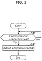
- FIG. 2 is a flowchart illustrating one example of the operation of anomaly detection device 10 according to Embodiment 1.
- Determiner 11 determines whether the communication connection via the communication line connecting the device and the voltage converter including the communication function has been lost (Step S11). For example, DC/DC converter 31 and DC/DC converter 32 regularly transmit and receive heartbeats for confirming that the communication connection between DC/DC converter 31 and DC/DC converter 32 is valid. Similarly, for example, DC/DC converters 31, 33 transmit and receive heartbeats, DC/DC converter 31 and inverter 34 transmit and receive heartbeats, DC/DC converter 32 and storage battery 51 transmit and receive heartbeats, and DC/DC converter 33 and storage battery 52 transmit and receive heartbeats.
- DC/DC converters 31, 32, 33 and inverter 34 notify anomaly detection device 10 of this failure.
- determiner 11 can determine whether the communication connection via the communication line connecting the device and the voltage converter including the communication function has been lost. For example, when anomaly detection device 10 is notified by DC/DC converter 32 of the failure to regularly receive heartbeats from storage battery 51, anomaly detection device 10 can determine that the communication connection via wiring 22, which connects DC/DC converter 32 and storage battery 51, has been lost.
- Step S11 determines that the communication connection via the communication line connecting the voltage converter and the device has not been lost (No in Step S11). the process in Step S11 is continuously performed.
- the anomalous signal includes a signal for interrupting the supply of electric power from the voltage converter to the device.
- the anomalous signal may include a signal for reporting the anomaly to a user, a manager, or the like of solar power generation system 1; outputter 12 may use this signal to notify that there is an anomaly in wiring 22.
- anomaly detection device 10 may be provided in one of DC/DC converters 31, 32, 33 and inverter 34.
- anomaly detection device 10 includes: determiner 11 that determines whether a communication connection via a communication line connecting a device and a voltage converter including a communication function has been lost; and outputter 12 that outputs an anomalous signal when it is determined that the communication connection has been lost.
- the communication line may also function as a direct-current power line connecting the voltage converter and the device.
- the direct-current power line which is used to supply electric power is associated with safety, meaning that the importance of detecting an anomaly in the direct-current power line is high. This is because there is a risk that an anomaly in the direct-current power line may cause an electrical fire due to electrical leakage, a short circuit, an arc discharge, or the like. According to this aspect, it is possible to easily detect such an anomaly in the direct-current power line by determining whether the communication connection has been lost.
- the anomalous signal may include a signal for interrupting the supply of electric power from the voltage converter to the device.
- Embodiment 1 has thus far described an example where the anomaly detection device is provided in the solar power generation system, but the anomaly detection device may be provided in an indoor wiring system. This will be described with reference to FIG. 3 .
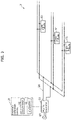
- FIG. 3 is a configuration diagram illustrating one example of indoor wiring system 2 according to Embodiment 2. Note that system power supply 40 connected to indoor wiring system 2 is also illustrated in FIG. 3 .
- System power supply 40 supplies alternating-current power generated at a power station or the like.
- Indoor wiring system 2 includes AC/DC converter 30, wiring 20, light fixtures 53, 54, 55, and anomaly detection device 10.
- AC/DC converter 30, wiring 20, light fixtures 53, 54, 55, and anomaly detection device 10 are installed inside a facility such as a detached house, an apartment, a building, or a factory.
- AC/DC converter 30 is a voltage converter that receives the alternating-current power from system power supply 40, converts the received alternating-current power into direct-current power, and outputs the direct-current power.
- AC/DC converter 30 outputs, to light fixtures 53, 54, 55, the direct-current power resulting from the conversion.
- AC/DC converter 30 includes a positive electrode and a negative electrode; a positive electrode-side direct-current power line is connected to the positive electrode, and a negative electrode-side direct-current power line is connected to the negative electrode.
- This positive electrode-side direct-current power line and this negative electrode-side direct-current power line are collectively referred to as wiring 20.
- Wiring 20 extends from AC/DC converter 30 and branches toward light fixtures 53, 54, 55, for example.
- the direct-current power is supplied from AC/DC converter 30 to light fixtures 53, 54, 55 through wiring 20.
- AC/DC converter 30 includes a semiconductor switch that turns ON and OFF the supply of electric power to light fixtures 53, 54, 55 through wiring
- AC/DC converter 30 is one example of the voltage converter including a communication function.
- Each of light fixtures 53, 54, 55 is one example of the device that communicates with AC/DC converter 30.
- the communication connection between AC/DC converter 30 and each of light fixtures 53, 54, 55 is performed through a communication line.
- Wiring 20 is one example of the communication line.
- wiring 20 is a direct-current power line, and the communication line also functions as a direct-current power line that connects AC/DC converter 30 and each of light fixtures 53, 54, 55.
- AC/DC converter 30 and each of light fixtures 53, 54, 55 communicate with each other by way of PLC or PoE using wiring 20 functioning as both the communication line and the direct-current power line.
- the device is not particularly limited to the light fixture as long as the device is provided indoors.
- the device may be a loudspeaker, a microphone, or the like.
- the electric current detection means, the voltage detection means, or the like is provided in wiring 20 20, an anomaly (for example, damage or rupture) in the wiring can be detected, but providing the electric current detection means, the voltage detection means, or the like leads to increased size and cost of the system.
- anomaly detection device 10 is used in the present embodiment as well.
- Anomaly detection device 10 that is the same as that according to Embodiment 1 is used; the present embodiment is different from Embodiment 1 in that anomaly detection device 10 is applied to indoor wiring system 2.
- AC/DC converter 30 and light fixture 53 regularly transmit and receive heartbeats for confirming that the communication connection between AC/DC converter 30 and light fixture 53 is valid.
- AC/DC converter 30 and light fixture 54 transmit and receive heartbeats
- AC/DC converter 30 and light fixture 55 transmit and receive heartbeats.
- AC/DC converter 30 fails to regularly receive heartbeats from light fixture 53, 54, or 55, AC/DC converter 30 notifies anomaly detection device 10 of this failure.
- determiner 11 and outputter 12 are the same as those described in Embodiment 1 and as such, description thereof will be omitted.
- indoor wiring system 2 includes anomaly detection device 10, a communication line (for example, wiring 20), and a device (for example, light fixtures 53, 54, 55) provided indoors.
- anomaly detection device 10 may be applied to indoor wiring system 2; it is possible to provide indoor wiring system 2 capable of easily detecting an anomaly in the wiring.
- the embodiments have thus far described examples where the communication line also functions as a direct-current power line connecting the voltage converter and the device, but the communication line does not need to function as a direct-current power line.
- determiner 11 may identify the type, etc., of the anomaly by analyzing the frequency components of electrical parameters (for example, an electric current or a voltage) obtained from the electric current detection means or the voltage detection means.
- the embodiments have thus far described examples where the anomaly detection device is applied to the solar power generation system and the indoor wiring system, but the examples of application are not limited to these examples.
- Other examples of application of the anomaly detection device according to the present invention (specifically, the anomaly detection device capable of easily detecting an anomaly in the wiring) will be described with reference to FIG. 4 .
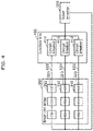
- FIG. 4 is a diagram for describing an example of application of the anomaly detection device according to the present invention.
- the anomaly detection device is applied to a system in which solar inverter 500 converts direct-current power supplied thereto from solar panel 310 through wiring into alternating-current power, for example.
- solar inverter 500 converts direct-current power supplied thereto from solar panel 310 through wiring into alternating-current power
- two or more (for example, three) sets of two or more (for example, three) solar panels 310 connected in series by a single line (string) of wiring 600 are arranged to form solar cell array 300.
- Two or more lines of wiring 600 are put together by junction box 400 and are connected to solar inverter 500.
- Wiring 600 is a communication line.
- circuit breaker 410 is provided for each line of wiring 600; in this example, circuit breaker 410 is provided in junction box 400. Note that circuit breaker 410 does not need to be provided in junction box 400.
- circuit breaker 410 may be provided between junction box 400 and solar cell array 300 or may be provided between junction box 400 and solar inverter 500 instead of being provided for each line of wiring 600.
- Solar panel 310 includes solar panel attachment module 320 which converts a signal to be output from solar panel 310, for example.
- Solar panel attachment module 320 is, for example, a DC/DC converter that optimizes the amount of electric power to be generated by each solar panel 310. Note that solar panel 310 does not need to include solar panel attachment module 320.
- Solar inverter 500 includes a voltage converter (for example, DC/DC converter) and a converter (for example, inverter) that converts electric power (direct-current power) output from the voltage converter into alternating current power.
- a voltage converter for example, DC/DC converter
- a converter for example, inverter
- solar inverter 500 may include the anomaly detection device. When it is determined that an electric arc has occurred, solar inverter 500 is stopped.
- circuit breaker 410 may include the anomaly detection device. When it is determined that an anomaly has occurred, circuit breaker 410 shuts off an electric current flowing through wiring 600.
- solar panel 310 or solar panel attachment module 320 may include the anomaly detection device. When it is determined that an anomaly has occurred, solar panel 310 or solar panel attachment module 320 stops the output to wiring 600.
- junction box 400 may include the anomaly detection device. When it is determined that an anomaly has occurred, junction box 400 shuts off, via circuit breaker 410 or the like, an electric current flowing through wiring 600, for example.
- the anomaly detection device can be applied to not only those cited above, but also any system in which an anomaly in wiring needs to be detected.
- solar inverter 500 may include the anomaly detection device, the voltage converter, and the converter that converts the electric power output from the voltage converter.
- Circuit breaker 410 may include the anomaly detection device, and when it is determined that the communication connection has been lost, shut off an electric current flowing through the communication line.
- Solar panel 310 may include the anomaly detection device and may generate electric power using sunlight.
- Solar panel attachment module 320 may include the anomaly detection device and may convert a signal to be output from solar panel 310.
- Junction box 400 may include the anomaly detection device and may connect solar panel 310 and solar inverter 500.
- the present invention can be implemented not only as an anomaly detection device, but also as an anomaly detection method including steps (processes) which the structural elements included in the anomaly detection device perform.
- the anomaly detection method includes: determining whether the communication connection via a communication line connecting a device and a voltage converter including a communication function has been lost (Step S11); and outputting an anomalous signal when it is determined that the communication connection has been lost (Yes in Step S11) (Step S12), as illustrated in FIG. 2 .
- these steps may be performed by a computer (computer system).
- the present invention can be implemented as a program which causes the computer to perform the steps included in the method.
- the present invention can be implemented as a non-transitory, computer-readable recording medium such as compact disc read-only memory (CD-ROM) including the program recorded thereon.
- CD-ROM compact disc read-only memory
- the anomaly detection device may be provided as software for a general-purpose computer such as a personal computer.
Landscapes
- Engineering & Computer Science (AREA)
- Theoretical Computer Science (AREA)
- Power Engineering (AREA)
- Physics & Mathematics (AREA)
- General Engineering & Computer Science (AREA)
- General Physics & Mathematics (AREA)
- Photovoltaic Devices (AREA)
- Inverter Devices (AREA)
Abstract
Description
- The present invention relates to anomaly detection devices, anomaly detection methods, programs, indoor wiring systems, solar inverters, circuit breakers, solar panels, solar panel attachment modules, and junction boxes.
- Conventionally, there is a known system that converts direct-current power supplied thereto from a photovoltaic (PV) panel (solar panel) or the like via wiring into alternating-current power using devices such as an inverter. A report indicates that such wiring connecting a direct-current power supply and a device is damaged or ruptured due to an external factor, degradation over time, or the like. There are cases where an anomaly such as an electric arc (i.e., arc discharge) occurs due to damage or the like of such wiring. Thus, a detection means for detecting an anomaly such as an electric arc in wiring has been proposed (for example, Patent Literature (PTL) 1).
- [PTL 1]
Japanese Unexamined Patent Application No. 2011-007765 - However, in
PTL 1, a voltage detection means for measuring a voltage in wiring and an electric current detection means for measuring an electric current in wiring need to be provided as the means for detecting an anomaly in wiring, which leads to increased size and cost of the system. - Thus, the present invention provides an anomaly detection device, etc., capable of easily detecting an anomaly in wiring.
- An anomaly detection device according to one aspect of the present invention includes: a determiner that determines whether a communication connection via a communication line connecting a device and a voltage converter including a communication function has been lost; and an outputter that outputs an anomalous signal when it is determined that the communication connection has been lost.
- An anomaly detection method according to one aspect of the present invention includes: determining whether a communication connection via a communication line connecting a device and a voltage converter including a communication function has been lost; and outputting an anomalous signal when it is determined that the communication connection has been lost.
- A program according to one aspect of the present invention causes a computer to perform the above-described anomaly detection method.
- An indoor wiring system according to one aspect of the present invention includes: the above-described anomaly detection device; the communication line; and a device provided indoors and connected to the communication line.
- A solar inverter according to one aspect of the present invention includes: the above-described anomaly detection device; the voltage converter; and a converter that converts electric power output from the voltage converter.
- A circuit breaker according to one aspect of the present invention includes: the above-described anomaly detection device. When it is determined that the communication connection has been lost, the circuit breaker shuts off an electric current flowing through the communication line.
- A solar panel according to one aspect of the present invention includes: the above-described anomaly detection device. The solar panel generates electric power using sunlight.
- A solar panel attachment module according to one aspect of the present invention includes: the above-described anomaly detection device. The solar panel attachment module converts a signal output from a solar panel.
- A junction box according to one aspect of the present invention includes: the above-described anomaly detection device. The junction box connects a solar panel and a solar inverter.
- According to one aspect of the present invention, an anomaly in wiring can be easily detected.
-
- [
FIG. 1 ]
FIG. 1 is a configuration diagram illustrating one example of a solar power generation system according toEmbodiment 1. - [
FIG. 2 ]
FIG. 2 is a flowchart illustrating one example of the operation of an anomaly detection device according toEmbodiment 1. - [
FIG. 3 ]
FIG. 3 is a configuration diagram illustrating one example of an indoor wiring system according toEmbodiment 2. - [
FIG. 4 ]
FIG. 4 is a diagram for describing an example of application of an anomaly detection device according to the present invention. - Hereinafter, embodiments of the present invention will be described with reference to the Drawings. Note that each embodiment described below shows a specific example of the present invention. Therefore, the numerical values, shapes, materials, structural elements, the arrangement and connection of the structural elements, steps, the processing order of the steps, etc. shown in the following embodiments are mere examples and are not intended to limit the present invention.
- Note that the figures are schematic diagrams and are not necessarily precise illustrations. In the figures, substantially identical elements are assigned the same reference signs, and overlapping description is omitted or simplified.
-
FIG. 1 is a configuration diagram illustrating one example of solarpower generation system 1 according toEmbodiment 1. - Solar
power generation system 1 includessolar panel 41,storage batteries DC converters inverter 34, andanomaly detection device 10. -
Solar panel 41 generates direct-current power by generating electric power using sunlight. The direct-current power generated bysolar panel 41 is supplied to DC/DC converter 31. -
Storage battery 51 stores the direct-current power received from DC/DC converter 32, andstorage battery 52 stores the direct-current power received from DC/DC converter 33. For example,storage batteries - DC/
DC converters DC converters - DC/
DC converter 31 increases or decreases the voltage of the direct-current power supplied thereto fromsolar panel 41 and outputs the direct-current power to DC/DC converters DC converter 31 includes a positive electrode and a negative electrode; a positive electrode-side direct-current power line is connected to the positive electrode, and a negative electrode-side direct-current power line is connected to the negative electrode. This positive electrode-side direct-current power line and this negative electrode-side direct-current power line are collectively referred to aswiring 21.Wiring 21 extends from DC/DC converter 31 and branches toward DC/DC converters DC converter 31 to DC/DC converters wiring 21. For example, DC/DC converter 31 includes a semiconductor switch that turns ON and OFF the supply of electric power to DC/DC converters wiring 21. - DC/
DC converter 31 is one example of the voltage converter including a communication function. Each of DC/DC converters inverter 34 is one example of the device that communicates with DC/DC converter 31. The communication connection between DC/DC converter 31 and each of DC/DC converters inverter 34 is performed through a communication line.Wiring 21 is one example of the communication line. As described above,wiring 21 is a direct-current power line, and the communication line also functions as a direct-current power line that connects DC/DC converter 31 and each of DC/DC converters DC converter 31 communicates with each of DC/DC converters wiring 21 functioning as both the communication line and the direct-current power line. - DC/
DC converter 32 increases or decreases the voltage of the direct-current power supplied thereto from DC/DC converter 31 and outputs the direct-current power tostorage battery 51. DC/DC converter 32 includes a positive electrode and a negative electrode; a positive electrode-side direct-current power line is connected to the positive electrode, and a negative electrode-side direct-current power line is connected to the negative electrode. This positive electrode-side direct-current power line and this negative electrode-side direct-current power line are collectively referred to as wiring 22. The direct-current power is supplied from DC/DC converter 32 tostorage battery 51 through wiring 22. For example, DC/DC converter 32 includes a semiconductor switch that turns ON and OFF the supply of electric power tostorage battery 51 through wiring 22. - DC/
DC converter 32 is one example of the voltage converter including a communication function. In other words, DC/DC converter 32 is a device that communicates with DC/DC converter 31, which is a voltage converter, as well as being a voltage converter.Storage battery 51 is one example of the device that communicates with DC/DC converter 32. The communication connection between DC/DC converter 32 andstorage battery 51 is performed through a communication line. Wiring 22 is one example of the communication line. As described above, wiring 22 is a direct-current power line, and the communication line also functions as a direct-current power line that connects DC/DC converter 32 andstorage battery 51. For example, DC/DC converter 32 andstorage battery 51 communicate with each other by way of PLC or PoE using wiring 22 functioning as both the communication line and the direct-current power line. - DC/
DC converter 33 increases or decreases the voltage of the direct-current power supplied thereto from DC/DC converter 31 and outputs the direct-current power tostorage battery 52. DC/DC converter 33 includes a positive electrode and a negative electrode; a positive electrode-side direct-current power line is connected to the positive electrode, and a negative electrode-side direct-current power line is connected to the negative electrode. This positive electrode-side direct-current power line and this negative electrode-side direct-current power line are collectively referred to aswiring 23. The direct-current power is supplied from DC/DC converter 33 tostorage battery 52 throughwiring 23. For example, DC/DC converter 33 includes a semiconductor switch that turns ON and OFF the supply of electric power tostorage battery 52 throughwiring 23. - DC/
DC converter 33 is one example of the voltage converter including a communication function. In other words, DC/DC converter 33 is a device that communicates with DC/DC converter 31, which is a voltage converter, as well as being a voltage converter.Storage battery 52 is one example of the device that communicates with DC/DC converter 33. The communication connection between DC/DC converter 33 andstorage battery 52 is performed through a communication line.Wiring 23 is one example of the communication line. As described above, wiring 23 is a direct-current power line, and the communication line also functions as a direct-current power line that connects DC/DC converter 33 andstorage battery 52. For example, DC/DC converter 33 andstorage battery 52 communicate with each other by way of PLC orPoE using wiring 23 functioning as both the communication line and the direct-current power line. -
Inverter 34 converts, into alternating-current power, the direct-current power supplied thereto from DC/DC converter 31 and outputs the alternating-current power.Inverter 34, which uses the maximum power point tracking (MPPT) technology, for example, adjusts the electric current and the voltage of the direct-current power supplied thereto from DC/DC converter 31 so as to have values that maximize the electric power. For example,inverter 34 converts the direct-current power into alternating-current power having a voltage of 100 V and a frequency of 50 Hz or 60 Hz. This alternating-current power is used in home appliances and the like. - For example, when the electric current detection means, the voltage detection means, or the like is provided in wiring, an anomaly (for example, damage or rupture) in the wiring can be detected, but providing the electric current detection means, the voltage detection means, or the like leads to increased size and cost of the system.
- Thus,
anomaly detection device 10 is used in order to easily detect an anomaly in the wiring.Anomaly detection device 10 is, for example, a microcomputer. The microcomputer is a semiconductor integrated circuit or the like including read-only memory (ROM) and random-access memory (RAM) each having a program stored therein, a processor (a central processing unit) (CPU) that executes the program, a timer, an A/D converter, a D/A converter, and the like. Note thatanomaly detection device 10 may be provided as hardware using a dedicated electronic circuit including an A/D converter, a logical circuit, a gate array, a D/A converter, and the like.Anomaly detection device 10 is connected to DC/DC converters inverter 34, for example, via wired or wireless connection so as to allow communication therebetween;anomaly detection device 10 can receive notifications from DC/DC converters inverter 34. -
Anomaly detection device 10 includesdeterminer 11 andoutputter 12.Determiner 11 andoutputter 12 are each implemented by the processor executing the program stored in the memory. The operations ofdeterminer 11 andoutputter 12 will be described with reference toFIG. 2 . -
FIG. 2 is a flowchart illustrating one example of the operation ofanomaly detection device 10 according toEmbodiment 1. -
Determiner 11 determines whether the communication connection via the communication line connecting the device and the voltage converter including the communication function has been lost (Step S11). For example, DC/DC converter 31 and DC/DC converter 32 regularly transmit and receive heartbeats for confirming that the communication connection between DC/DC converter 31 and DC/DC converter 32 is valid. Similarly, for example, DC/DC converters DC converter 31 andinverter 34 transmit and receive heartbeats, DC/DC converter 32 andstorage battery 51 transmit and receive heartbeats, and DC/DC converter 33 andstorage battery 52 transmit and receive heartbeats. For example, when DC/DC converters inverter 34 fail to regularly receive heartbeats from the corresponding communication partners, DC/DC converters inverter 34 notifyanomaly detection device 10 of this failure. With this,determiner 11 can determine whether the communication connection via the communication line connecting the device and the voltage converter including the communication function has been lost. For example, whenanomaly detection device 10 is notified by DC/DC converter 32 of the failure to regularly receive heartbeats fromstorage battery 51,anomaly detection device 10 can determine that the communication connection via wiring 22, which connects DC/DC converter 32 andstorage battery 51, has been lost. - When
determiner 11 determines that the communication connection via the communication line connecting the voltage converter and the device has not been lost (No in Step S11), the process in Step S11 is continuously performed. - When it is determined that the communication connection has been lost (Yes in Step S11),
outputter 12 outputs an anomalous signal (Step S12). For example, the anomalous signal includes a signal for interrupting the supply of electric power from the voltage converter to the device. For example, when it is determined that the communication connection between DC/DC converter 32 andstorage battery 51 has been lost,outputter 12 outputs, to DC/DC converter 32, a signal for interrupting the supply of electric power from DC/DC converter 32 tostorage battery 51. DC/DC converter 32 receives this signal and, accordingly, interrupts the supply of electric power tostorage battery 51 by controlling the semiconductor switch that turns ON and OFF the supply of electric power tostorage battery 51 via wiring 22, for example. Furthermore, the anomalous signal may include a signal for reporting the anomaly to a user, a manager, or the like of solarpower generation system 1; outputter 12 may use this signal to notify that there is an anomaly in wiring 22. - Note that
anomaly detection device 10 may be provided in one of DC/DC converters inverter 34. - As described above,
anomaly detection device 10 according to the present embodiment includes:determiner 11 that determines whether a communication connection via a communication line connecting a device and a voltage converter including a communication function has been lost; andoutputter 12 that outputs an anomalous signal when it is determined that the communication connection has been lost. - With this, it is possible to detect an anomaly in wiring by only determining whether the communication connection has been lost. Stated differently, there is no need to provide the voltage detection means, the electric current detection means, or the like in the wiring, and an anomaly in the wiring can be easily detected.
- For example, the communication line may also function as a direct-current power line connecting the voltage converter and the device.
- The direct-current power line which is used to supply electric power is associated with safety, meaning that the importance of detecting an anomaly in the direct-current power line is high. This is because there is a risk that an anomaly in the direct-current power line may cause an electrical fire due to electrical leakage, a short circuit, an arc discharge, or the like. According to this aspect, it is possible to easily detect such an anomaly in the direct-current power line by determining whether the communication connection has been lost.
- For example, the anomalous signal may include a signal for interrupting the supply of electric power from the voltage converter to the device.
- With this, when an anomaly in the wiring is detected, the supply of electric power from the voltage converter to the device can be interrupted, and thus safety is secured.
-
Embodiment 1 has thus far described an example where the anomaly detection device is provided in the solar power generation system, but the anomaly detection device may be provided in an indoor wiring system. This will be described with reference toFIG. 3 . -
FIG. 3 is a configuration diagram illustrating one example ofindoor wiring system 2 according toEmbodiment 2. Note thatsystem power supply 40 connected toindoor wiring system 2 is also illustrated inFIG. 3 . -
System power supply 40 supplies alternating-current power generated at a power station or the like. -
Indoor wiring system 2 includes AC/DC converter 30, wiring 20,light fixtures anomaly detection device 10. AC/DC converter 30, wiring 20,light fixtures anomaly detection device 10 are installed inside a facility such as a detached house, an apartment, a building, or a factory. - AC/
DC converter 30 is a voltage converter that receives the alternating-current power fromsystem power supply 40, converts the received alternating-current power into direct-current power, and outputs the direct-current power. AC/DC converter 30 outputs, tolight fixtures DC converter 30 includes a positive electrode and a negative electrode; a positive electrode-side direct-current power line is connected to the positive electrode, and a negative electrode-side direct-current power line is connected to the negative electrode. This positive electrode-side direct-current power line and this negative electrode-side direct-current power line are collectively referred to aswiring 20.Wiring 20 extends from AC/DC converter 30 and branches towardlight fixtures DC converter 30 tolight fixtures wiring 20. For example, AC/DC converter 30 includes a semiconductor switch that turns ON and OFF the supply of electric power tolight fixtures wiring 20. - AC/
DC converter 30 is one example of the voltage converter including a communication function. Each oflight fixtures DC converter 30. The communication connection between AC/DC converter 30 and each oflight fixtures Wiring 20 is one example of the communication line. As described above, wiring 20 is a direct-current power line, and the communication line also functions as a direct-current power line that connects AC/DC converter 30 and each oflight fixtures DC converter 30 and each oflight fixtures PoE using wiring 20 functioning as both the communication line and the direct-current power line. - Note that the device is not particularly limited to the light fixture as long as the device is provided indoors. For example, the device may be a loudspeaker, a microphone, or the like.
- For example, when the electric current detection means, the voltage detection means, or the like is provided in
wiring 20, an anomaly (for example, damage or rupture) in the wiring can be detected, but providing the electric current detection means, the voltage detection means, or the like leads to increased size and cost of the system. - Thus, in order to easily detect an anomaly in the wiring,
anomaly detection device 10 is used in the present embodiment as well.Anomaly detection device 10 that is the same as that according toEmbodiment 1 is used; the present embodiment is different fromEmbodiment 1 in thatanomaly detection device 10 is applied toindoor wiring system 2. - For example, AC/
DC converter 30 andlight fixture 53 regularly transmit and receive heartbeats for confirming that the communication connection between AC/DC converter 30 andlight fixture 53 is valid. Similarly, for example, AC/DC converter 30 andlight fixture 54 transmit and receive heartbeats, and AC/DC converter 30 andlight fixture 55 transmit and receive heartbeats. For example, when AC/DC converter 30 fails to regularly receive heartbeats fromlight fixture DC converter 30 notifiesanomaly detection device 10 of this failure. - The operations of
determiner 11 andoutputter 12 are the same as those described inEmbodiment 1 and as such, description thereof will be omitted. - As described above,
indoor wiring system 2 according to the present embodiment includesanomaly detection device 10, a communication line (for example, wiring 20), and a device (for example,light fixtures - Thus,
anomaly detection device 10 may be applied toindoor wiring system 2; it is possible to provideindoor wiring system 2 capable of easily detecting an anomaly in the wiring. - The anomaly detection device, etc., according to the embodiments have been described thus far, but the present invention is not limited to the embodiments described above.
- For example, the embodiments have thus far described examples where the communication line also functions as a direct-current power line connecting the voltage converter and the device, but the communication line does not need to function as a direct-current power line.
- For example, the embodiments have thus far described examples where the electric current detection means or the voltage detection means is not provided in the wiring, but the electric current detection means or the voltage detection means may be provided in the wiring. After determining that the communication connection has been lost,
determiner 11 may identify the type, etc., of the anomaly by analyzing the frequency components of electrical parameters (for example, an electric current or a voltage) obtained from the electric current detection means or the voltage detection means. - For example, the embodiments have thus far described examples where the anomaly detection device is applied to the solar power generation system and the indoor wiring system, but the examples of application are not limited to these examples. Other examples of application of the anomaly detection device according to the present invention (specifically, the anomaly detection device capable of easily detecting an anomaly in the wiring) will be described with reference to
FIG. 4 . -
FIG. 4 is a diagram for describing an example of application of the anomaly detection device according to the present invention. - The anomaly detection device according to the present invention is applied to a system in which
solar inverter 500 converts direct-current power supplied thereto fromsolar panel 310 through wiring into alternating-current power, for example. In this example of application, two or more (for example, three) sets of two or more (for example, three)solar panels 310 connected in series by a single line (string) ofwiring 600 are arranged to formsolar cell array 300. Two or more lines ofwiring 600 are put together byjunction box 400 and are connected tosolar inverter 500. Wiring 600 is a communication line. - For example,
circuit breaker 410 is provided for each line ofwiring 600; in this example,circuit breaker 410 is provided injunction box 400. Note thatcircuit breaker 410 does not need to be provided injunction box 400. For example,circuit breaker 410 may be provided betweenjunction box 400 andsolar cell array 300 or may be provided betweenjunction box 400 andsolar inverter 500 instead of being provided for each line ofwiring 600. -
Solar panel 310 includes solarpanel attachment module 320 which converts a signal to be output fromsolar panel 310, for example. Solarpanel attachment module 320 is, for example, a DC/DC converter that optimizes the amount of electric power to be generated by eachsolar panel 310. Note thatsolar panel 310 does not need to include solarpanel attachment module 320. -
Solar inverter 500 includes a voltage converter (for example, DC/DC converter) and a converter (for example, inverter) that converts electric power (direct-current power) output from the voltage converter into alternating current power. - For example,
solar inverter 500 may include the anomaly detection device. When it is determined that an electric arc has occurred,solar inverter 500 is stopped. - For example,
circuit breaker 410 may include the anomaly detection device. When it is determined that an anomaly has occurred,circuit breaker 410 shuts off an electric current flowing throughwiring 600. - Furthermore, for example,
solar panel 310 or solarpanel attachment module 320 may include the anomaly detection device. When it is determined that an anomaly has occurred,solar panel 310 or solarpanel attachment module 320 stops the output towiring 600. - Furthermore, for example,
junction box 400 may include the anomaly detection device. When it is determined that an anomaly has occurred,junction box 400 shuts off, viacircuit breaker 410 or the like, an electric current flowing throughwiring 600, for example. - Note that the anomaly detection device according to the present invention can be applied to not only those cited above, but also any system in which an anomaly in wiring needs to be detected.
- Thus,
solar inverter 500 may include the anomaly detection device, the voltage converter, and the converter that converts the electric power output from the voltage converter.Circuit breaker 410 may include the anomaly detection device, and when it is determined that the communication connection has been lost, shut off an electric current flowing through the communication line.Solar panel 310 may include the anomaly detection device and may generate electric power using sunlight. Solarpanel attachment module 320 may include the anomaly detection device and may convert a signal to be output fromsolar panel 310.Junction box 400 may include the anomaly detection device and may connectsolar panel 310 andsolar inverter 500. - Furthermore, the present invention can be implemented not only as an anomaly detection device, but also as an anomaly detection method including steps (processes) which the structural elements included in the anomaly detection device perform.
- Specifically, the anomaly detection method includes: determining whether the communication connection via a communication line connecting a device and a voltage converter including a communication function has been lost (Step S11); and outputting an anomalous signal when it is determined that the communication connection has been lost (Yes in Step S11) (Step S12), as illustrated in
FIG. 2 . - For example, these steps may be performed by a computer (computer system). The present invention can be implemented as a program which causes the computer to perform the steps included in the method. Furthermore, the present invention can be implemented as a non-transitory, computer-readable recording medium such as compact disc read-only memory (CD-ROM) including the program recorded thereon.
- For example, the anomaly detection device may be provided as software for a general-purpose computer such as a personal computer.
- Forms obtained by various modifications to the embodiments that can be conceived by a person having ordinary skill in the art, and forms configured by arbitrarily combining structural elements and functions in different embodiments which are within the scope of the essence of the present invention are included in the present invention.
-
- 1
- solar power generation system
- 2
- indoor wiring system
- 10
- anomaly detection device
- 11
- determiner
- 12
- outputter
- 20, 21, 22, 23, 600
- wiring
- 30
- AC/DC converter
- 31, 32, 33
- DC/DC converter
- 34
- inverter
- 40
- system power supply
- 41, 310
- solar panel
- 51, 52
- storage battery
- 53, 54, 55
- light fixture
- 300
- solar cell array
- 320
- solar panel attachment module
- 400
- junction box
- 410
- circuit breaker
- 500
- solar inverter
Claims (11)
- An anomaly detection device comprising:a determiner that determines whether a communication connection via a communication line connecting a device and a voltage converter including a communication function has been lost; andan outputter that outputs an anomalous signal when it is determined that the communication connection has been lost.
- The anomaly detection device according to claim 1, wherein
the communication line also functions as a direct-current power line connecting the voltage converter and the device. - The anomaly detection device according to claim 1 or 2, wherein
the anomalous signal includes a signal for interrupting supply of electric power from the voltage converter to the device. - An anomaly detection method comprising:determining whether a communication connection via a communication line connecting a device and a voltage converter including a communication function has been lost; andoutputting an anomalous signal when it is determined that the communication connection has been lost.
- A program for causing a computer to perform the anomaly detection method according to claim 4.
- An indoor wiring system comprising:the anomaly detection device according to any one of claims 1 to 3;the communication line; anda device provided indoors and connected to the communication line.
- A solar inverter comprising:the anomaly detection device according to any one of claims 1 to 3;the voltage converter; anda converter that converts electric power output from the voltage converter.
- A circuit breaker comprising:the anomaly detection device according to any one of claims 1 to 3, whereinwhen it is determined that the communication connection has been lost, the circuit breaker shuts off an electric current flowing through the communication line.
- A solar panel comprising:the anomaly detection device according to any one of claims 1 to 3, whereinthe solar panel generates electric power using sunlight.
- A solar panel attachment module comprising:the anomaly detection device according to any one of claims 1 to 3, whereinthe solar panel attachment module converts a signal output from a solar panel.
- A junction box comprising:the anomaly detection device according to any one of claims 1 to 3, whereinthe junction box connects a solar panel and a solar inverter.
Applications Claiming Priority (2)
| Application Number | Priority Date | Filing Date | Title |
|---|---|---|---|
| JP2020041739 | 2020-03-11 | ||
| PCT/JP2021/008296 WO2021182262A1 (en) | 2020-03-11 | 2021-03-03 | Abnormality detection device, abnormality detection method, program, indoor wiring system, power conditioner, breaker, solar panel, solar panel accessory module, and junction box |
Publications (3)
| Publication Number | Publication Date |
|---|---|
| EP4120541A1 true EP4120541A1 (en) | 2023-01-18 |
| EP4120541A4 EP4120541A4 (en) | 2023-07-19 |
| EP4120541B1 EP4120541B1 (en) | 2025-10-29 |
Family
ID=77672248
Family Applications (1)
| Application Number | Title | Priority Date | Filing Date |
|---|---|---|---|
| EP21767286.4A Active EP4120541B1 (en) | 2020-03-11 | 2021-03-03 | Abnormality detection device, abnormality detection method, program, indoor wiring system, power conditioner, breaker, solar panel, solar panel accessory module, and junction box |
Country Status (5)
| Country | Link |
|---|---|
| US (1) | US20230094178A1 (en) |
| EP (1) | EP4120541B1 (en) |
| JP (1) | JP7357249B2 (en) |
| CN (1) | CN115176407B (en) |
| WO (1) | WO2021182262A1 (en) |
Families Citing this family (3)
| Publication number | Priority date | Publication date | Assignee | Title |
|---|---|---|---|---|
| CN120856042A (en) * | 2023-11-30 | 2025-10-28 | 华为数字能源技术有限公司 | Power device, power device control method and photovoltaic power generation system |
| CN120196469A (en) * | 2023-12-22 | 2025-06-24 | 富联精密电子(天津)有限公司 | Fault detection systems, storage devices and servers |
| CN119232559B (en) * | 2024-08-19 | 2026-04-28 | 东风汽车集团股份有限公司 | Methods, media, and products for preventing DC-DC CAN signal transmission and reception failures |
Family Cites Families (16)
| Publication number | Priority date | Publication date | Assignee | Title |
|---|---|---|---|---|
| JP3655295B2 (en) * | 2002-07-22 | 2005-06-02 | 富士通株式会社 | Inverter current detection method, current detection circuit thereof, abnormality detection method thereof, abnormality detection circuit thereof, display device and information processing device |
| JP2008042999A (en) * | 2006-08-02 | 2008-02-21 | Matsushita Electric Works Ltd | Power supply device |
| US11228278B2 (en) * | 2007-11-02 | 2022-01-18 | Tigo Energy, Inc. | System and method for enhanced watch dog in solar panel installations |
| JP5419579B2 (en) | 2009-05-28 | 2014-02-19 | 京セラ株式会社 | Arc detection means and control means and communication means using the same |
| WO2011133928A2 (en) * | 2010-04-22 | 2011-10-27 | Tigo Energy, Inc. | System and method for enhanced watch dog in solar panel installations |
| JP2012019601A (en) | 2010-07-07 | 2012-01-26 | Sony Corp | Electric power system, electric power reception device, and electric power transmission control method |
| JP5218483B2 (en) * | 2010-07-09 | 2013-06-26 | ソニー株式会社 | Power control device |
| US8751036B2 (en) * | 2011-09-28 | 2014-06-10 | Causam Energy, Inc. | Systems and methods for microgrid power generation management with selective disconnect |
| JP2016001948A (en) * | 2014-06-11 | 2016-01-07 | 住友電気工業株式会社 | Monitoring system for photovoltaic power generation |
| US10348094B2 (en) * | 2015-01-28 | 2019-07-09 | Abb Schweiz Ag | Energy panel arrangement shutdown |
| EP3254373B1 (en) * | 2015-02-06 | 2018-11-21 | ABB Schweiz AG | Photovoltaic string combiner with modular platform architecture |
| KR101863761B1 (en) | 2016-08-22 | 2018-06-01 | 주식회사 루텍 | System for Motor Control Center having Redundant Structure of Integration Module and Communication |
| JP6982820B2 (en) * | 2017-12-27 | 2021-12-17 | パナソニックIpマネジメント株式会社 | Control command system and power conversion system |
| JP7108860B2 (en) * | 2019-06-27 | 2022-07-29 | パナソニックIpマネジメント株式会社 | Power supply system and power supply system control method |
| US11923670B2 (en) * | 2020-03-11 | 2024-03-05 | Panasonic Intellectual Property Management Co., Ltd. | ARC detection device, solar inverter, indoor wiring system, circuit breaker, solar panel, solar panel attachment module, and junction box |
| JP7546224B2 (en) * | 2020-08-26 | 2024-09-06 | パナソニックIpマネジメント株式会社 | ABNORMALITY DETECTION DEVICE, ABNORMALITY DETECTION METHOD, AND PROGRAM |
-
2021
- 2021-03-03 CN CN202180017304.7A patent/CN115176407B/en active Active
- 2021-03-03 US US17/908,691 patent/US20230094178A1/en not_active Abandoned
- 2021-03-03 WO PCT/JP2021/008296 patent/WO2021182262A1/en not_active Ceased
- 2021-03-03 JP JP2022505985A patent/JP7357249B2/en active Active
- 2021-03-03 EP EP21767286.4A patent/EP4120541B1/en active Active
Also Published As
| Publication number | Publication date |
|---|---|
| CN115176407A (en) | 2022-10-11 |
| US20230094178A1 (en) | 2023-03-30 |
| CN115176407B (en) | 2026-04-10 |
| JP7357249B2 (en) | 2023-10-06 |
| EP4120541A4 (en) | 2023-07-19 |
| EP4120541B1 (en) | 2025-10-29 |
| WO2021182262A1 (en) | 2021-09-16 |
| JPWO2021182262A1 (en) | 2021-09-16 |
Similar Documents
| Publication | Publication Date | Title |
|---|---|---|
| KR101535589B1 (en) | distributed inverter and intelligent gateway | |
| CN112803485B (en) | A photovoltaic fast shutdown system and its control method | |
| EP4120541A1 (en) | Abnormality detection device, abnormality detection method, program, indoor wiring system, power conditioner, breaker, solar panel, solar panel accessory module, and junction box | |
| KR101830666B1 (en) | Power conversion apparatus | |
| WO2011065278A1 (en) | Grid connection apparatus | |
| KR20120093671A (en) | Grid-connected generating system with photovoltaic and wind power hybrid generation and generator thereof | |
| US12184055B2 (en) | Arc detection device, solar inverter, indoor wiring system, breaker, solar panel, solar panel- attached module, and junction box | |
| US20230280387A1 (en) | Anomaly detection device, anomaly detection method, and recording medium | |
| US11923670B2 (en) | ARC detection device, solar inverter, indoor wiring system, circuit breaker, solar panel, solar panel attachment module, and junction box | |
| JP7482281B2 (en) | Power Conversion Systems | |
| WO2022066554A1 (en) | High-power microinverter and system | |
| EP4325691A1 (en) | Electric power conversion system and electric power conversion device | |
| WO2012063667A1 (en) | Dc power supply system | |
| US12149062B2 (en) | Arc detection device, indoor power line system, solar power generation system, and storage battery system | |
| JP2021063663A (en) | Arc detection device, breaker, power conditioner, photovoltaic panel, photovoltaic panel attachment module, junction box, arc detection system, and arc detection method | |
| KR101568712B1 (en) | An islanding detection apparatus and method with partial phase window monitoring method on grid connected inverter | |
| CN117749086A (en) | Arc discharge identification method, inverter and inverter system | |
| JP7108860B2 (en) | Power supply system and power supply system control method | |
| KR101417572B1 (en) | Energy storage system with function of uninterruptible power equipment | |
| JP2015042100A (en) | Power conditioner | |
| US20240072528A1 (en) | Arc detection device, breaker, power conditioner, solar panel, solar-panel-attached module, junction box, arc detection system, and arc detection method | |
| JP7246010B2 (en) | protector | |
| KR20240008642A (en) | Apparatus and method for detecting arc | |
| CN120784951A (en) | Photovoltaic power generation system, control method of converter and inverter | |
| TW202341600A (en) | Power conversion system |
Legal Events
| Date | Code | Title | Description |
|---|---|---|---|
| STAA | Information on the status of an ep patent application or granted ep patent |
Free format text: STATUS: THE INTERNATIONAL PUBLICATION HAS BEEN MADE |
|
| PUAI | Public reference made under article 153(3) epc to a published international application that has entered the european phase |
Free format text: ORIGINAL CODE: 0009012 |
|
| STAA | Information on the status of an ep patent application or granted ep patent |
Free format text: STATUS: REQUEST FOR EXAMINATION WAS MADE |
|
| 17P | Request for examination filed |
Effective date: 20220906 |
|
| AK | Designated contracting states |
Kind code of ref document: A1 Designated state(s): AL AT BE BG CH CY CZ DE DK EE ES FI FR GB GR HR HU IE IS IT LI LT LU LV MC MK MT NL NO PL PT RO RS SE SI SK SM TR |
|
| DAV | Request for validation of the european patent (deleted) | ||
| DAX | Request for extension of the european patent (deleted) | ||
| A4 | Supplementary search report drawn up and despatched |
Effective date: 20230615 |
|
| RIC1 | Information provided on ipc code assigned before grant |
Ipc: H02M 7/48 20070101AFI20230609BHEP |
|
| GRAP | Despatch of communication of intention to grant a patent |
Free format text: ORIGINAL CODE: EPIDOSNIGR1 |
|
| STAA | Information on the status of an ep patent application or granted ep patent |
Free format text: STATUS: GRANT OF PATENT IS INTENDED |
|
| INTG | Intention to grant announced |
Effective date: 20250624 |
|
| GRAS | Grant fee paid |
Free format text: ORIGINAL CODE: EPIDOSNIGR3 |
|
| GRAA | (expected) grant |
Free format text: ORIGINAL CODE: 0009210 |
|
| STAA | Information on the status of an ep patent application or granted ep patent |
Free format text: STATUS: THE PATENT HAS BEEN GRANTED |
|
| AK | Designated contracting states |
Kind code of ref document: B1 Designated state(s): AL AT BE BG CH CY CZ DE DK EE ES FI FR GB GR HR HU IE IS IT LI LT LU LV MC MK MT NL NO PL PT RO RS SE SI SK SM TR |
|
| REG | Reference to a national code |
Ref country code: CH Ref legal event code: F10 Free format text: ST27 STATUS EVENT CODE: U-0-0-F10-F00 (AS PROVIDED BY THE NATIONAL OFFICE) Effective date: 20251029 Ref country code: GB Ref legal event code: FG4D |
|
| REG | Reference to a national code |
Ref country code: IE Ref legal event code: FG4D |
|
| REG | Reference to a national code |
Ref country code: DE Ref legal event code: R096 Ref document number: 602021041318 Country of ref document: DE |
|
| REG | Reference to a national code |
Ref country code: NL Ref legal event code: MP Effective date: 20251029 |
|
| PG25 | Lapsed in a contracting state [announced via postgrant information from national office to epo] |
Ref country code: ES Free format text: LAPSE BECAUSE OF FAILURE TO SUBMIT A TRANSLATION OF THE DESCRIPTION OR TO PAY THE FEE WITHIN THE PRESCRIBED TIME-LIMIT Effective date: 20251029 |
|
| REG | Reference to a national code |
Ref country code: LT Ref legal event code: MG9D |
|
| PG25 | Lapsed in a contracting state [announced via postgrant information from national office to epo] |
Ref country code: NO Free format text: LAPSE BECAUSE OF FAILURE TO SUBMIT A TRANSLATION OF THE DESCRIPTION OR TO PAY THE FEE WITHIN THE PRESCRIBED TIME-LIMIT Effective date: 20260129 |
|
| PGFP | Annual fee paid to national office [announced via postgrant information from national office to epo] |
Ref country code: DE Payment date: 20260319 Year of fee payment: 6 |
|
| PG25 | Lapsed in a contracting state [announced via postgrant information from national office to epo] |
Ref country code: HR Free format text: LAPSE BECAUSE OF FAILURE TO SUBMIT A TRANSLATION OF THE DESCRIPTION OR TO PAY THE FEE WITHIN THE PRESCRIBED TIME-LIMIT Effective date: 20251029 Ref country code: FI Free format text: LAPSE BECAUSE OF FAILURE TO SUBMIT A TRANSLATION OF THE DESCRIPTION OR TO PAY THE FEE WITHIN THE PRESCRIBED TIME-LIMIT Effective date: 20251029 Ref country code: AT Free format text: LAPSE BECAUSE OF FAILURE TO SUBMIT A TRANSLATION OF THE DESCRIPTION OR TO PAY THE FEE WITHIN THE PRESCRIBED TIME-LIMIT Effective date: 20251029 |
|
| REG | Reference to a national code |
Ref country code: AT Ref legal event code: MK05 Ref document number: 1852825 Country of ref document: AT Kind code of ref document: T Effective date: 20251029 |
|
| PG25 | Lapsed in a contracting state [announced via postgrant information from national office to epo] |
Ref country code: NL Free format text: LAPSE BECAUSE OF FAILURE TO SUBMIT A TRANSLATION OF THE DESCRIPTION OR TO PAY THE FEE WITHIN THE PRESCRIBED TIME-LIMIT Effective date: 20251029 |
|
| PG25 | Lapsed in a contracting state [announced via postgrant information from national office to epo] |
Ref country code: RS Free format text: LAPSE BECAUSE OF FAILURE TO SUBMIT A TRANSLATION OF THE DESCRIPTION OR TO PAY THE FEE WITHIN THE PRESCRIBED TIME-LIMIT Effective date: 20260129 |
|
| PG25 | Lapsed in a contracting state [announced via postgrant information from national office to epo] |
Ref country code: IS Free format text: LAPSE BECAUSE OF FAILURE TO SUBMIT A TRANSLATION OF THE DESCRIPTION OR TO PAY THE FEE WITHIN THE PRESCRIBED TIME-LIMIT Effective date: 20260228 |
|
| PG25 | Lapsed in a contracting state [announced via postgrant information from national office to epo] |
Ref country code: PT Free format text: LAPSE BECAUSE OF FAILURE TO SUBMIT A TRANSLATION OF THE DESCRIPTION OR TO PAY THE FEE WITHIN THE PRESCRIBED TIME-LIMIT Effective date: 20260302 |
|
| PG25 | Lapsed in a contracting state [announced via postgrant information from national office to epo] |
Ref country code: PL Free format text: LAPSE BECAUSE OF FAILURE TO SUBMIT A TRANSLATION OF THE DESCRIPTION OR TO PAY THE FEE WITHIN THE PRESCRIBED TIME-LIMIT Effective date: 20251029 |
|
| PG25 | Lapsed in a contracting state [announced via postgrant information from national office to epo] |
Ref country code: LV Free format text: LAPSE BECAUSE OF FAILURE TO SUBMIT A TRANSLATION OF THE DESCRIPTION OR TO PAY THE FEE WITHIN THE PRESCRIBED TIME-LIMIT Effective date: 20251029 |