EP4120517A1 - Stator for rotating electrical machine, and rotating electrical machine - Google Patents
Stator for rotating electrical machine, and rotating electrical machine Download PDFInfo
- Publication number
- EP4120517A1 EP4120517A1 EP20924293.2A EP20924293A EP4120517A1 EP 4120517 A1 EP4120517 A1 EP 4120517A1 EP 20924293 A EP20924293 A EP 20924293A EP 4120517 A1 EP4120517 A1 EP 4120517A1
- Authority
- EP
- European Patent Office
- Prior art keywords
- bridge section
- coil segment
- linear part
- bridge
- inclination angle
- Prior art date
- Legal status (The legal status is an assumption and is not a legal conclusion. Google has not performed a legal analysis and makes no representation as to the accuracy of the status listed.)
- Withdrawn
Links
- 238000005452 bending Methods 0.000 claims abstract description 54
- 239000004020 conductor Substances 0.000 claims description 5
- 230000002093 peripheral effect Effects 0.000 description 6
- 238000003466 welding Methods 0.000 description 6
- 229910000831 Steel Inorganic materials 0.000 description 5
- 239000010959 steel Substances 0.000 description 5
- 230000007423 decrease Effects 0.000 description 4
- 238000010292 electrical insulation Methods 0.000 description 3
- 229910000976 Electrical steel Inorganic materials 0.000 description 2
- 238000012986 modification Methods 0.000 description 2
- 230000004048 modification Effects 0.000 description 2
- 230000000149 penetrating effect Effects 0.000 description 2
- RYGMFSIKBFXOCR-UHFFFAOYSA-N Copper Chemical compound [Cu] RYGMFSIKBFXOCR-UHFFFAOYSA-N 0.000 description 1
- XAGFODPZIPBFFR-UHFFFAOYSA-N aluminium Chemical compound [Al] XAGFODPZIPBFFR-UHFFFAOYSA-N 0.000 description 1
- 229910052782 aluminium Inorganic materials 0.000 description 1
- 230000004323 axial length Effects 0.000 description 1
- 239000011324 bead Substances 0.000 description 1
- 229910052802 copper Inorganic materials 0.000 description 1
- 239000010949 copper Substances 0.000 description 1
- 230000003247 decreasing effect Effects 0.000 description 1
- 210000003298 dental enamel Anatomy 0.000 description 1
- 230000006698 induction Effects 0.000 description 1
- 239000011810 insulating material Substances 0.000 description 1
- 239000000696 magnetic material Substances 0.000 description 1
- 230000005389 magnetism Effects 0.000 description 1
- 239000000463 material Substances 0.000 description 1
- 230000007935 neutral effect Effects 0.000 description 1
- 239000000843 powder Substances 0.000 description 1
- 238000006467 substitution reaction Methods 0.000 description 1
- 239000002966 varnish Substances 0.000 description 1
Images





Classifications
-
- H—ELECTRICITY
- H02—GENERATION; CONVERSION OR DISTRIBUTION OF ELECTRIC POWER
- H02K—DYNAMO-ELECTRIC MACHINES
- H02K3/00—Details of windings
- H02K3/04—Windings characterised by the conductor shape, form or construction, e.g. with bar conductors
- H02K3/12—Windings characterised by the conductor shape, form or construction, e.g. with bar conductors arranged in slots
-
- H—ELECTRICITY
- H02—GENERATION; CONVERSION OR DISTRIBUTION OF ELECTRIC POWER
- H02K—DYNAMO-ELECTRIC MACHINES
- H02K3/00—Details of windings
- H02K3/04—Windings characterised by the conductor shape, form or construction, e.g. with bar conductors
- H02K3/28—Layout of windings or of connections between windings
-
- H—ELECTRICITY
- H02—GENERATION; CONVERSION OR DISTRIBUTION OF ELECTRIC POWER
- H02K—DYNAMO-ELECTRIC MACHINES
- H02K15/00—Processes or apparatus specially adapted for manufacturing, assembling, maintaining or repairing of dynamo-electric machines
- H02K15/04—Processes or apparatus specially adapted for manufacturing, assembling, maintaining or repairing of dynamo-electric machines of windings prior to their mounting into the machines
- H02K15/0414—Processes or apparatus specially adapted for manufacturing, assembling, maintaining or repairing of dynamo-electric machines of windings prior to their mounting into the machines the windings consisting of separate elements, e.g. bars, segments or half coils
- H02K15/0421—Processes or apparatus specially adapted for manufacturing, assembling, maintaining or repairing of dynamo-electric machines of windings prior to their mounting into the machines the windings consisting of separate elements, e.g. bars, segments or half coils and consisting of single conductors, e.g. hairpins
-
- H—ELECTRICITY
- H02—GENERATION; CONVERSION OR DISTRIBUTION OF ELECTRIC POWER
- H02K—DYNAMO-ELECTRIC MACHINES
- H02K15/00—Processes or apparatus specially adapted for manufacturing, assembling, maintaining or repairing of dynamo-electric machines
- H02K15/06—Embedding prefabricated windings in the machines
- H02K15/062—Windings in slots; Salient pole windings
- H02K15/064—Windings consisting of separate segments
Definitions
- Embodiments of the present application relate generally to a stator of a rotary electric machine and a rotary electric machine.
- Rotary electric machines include a cylindrical stator and a rotor arranged rotatably in a field space of the stator.
- the stator includes a stator core including multi-layered annular electromagnetic steel plates, and a stator coil formed of a flat conductor and attached to the stator core. Coils formed of a plurality of coil segments bonded together in series include coil ends protruding outward from both end surfaces of the stator core in the axial direction. In recent years, demand for smaller stators of rotary electric machines is high.
- Patent Literature 1 JP 2016-152753 A
- Embodiments of the present application present a stator of a rotary electric machine which will miniaturize a stator core, and a rotary electric machine with such a stator.
- a stator of rotary electric machine comprises a stator core including a yoke, a plurality of teeth, one end surface positioned at one end of an axial direction, and other end surface positioned in the other end of the axial direction, the stator core forming slots each extending in a radial direction between the teeth adjacent to each other; and a plurality of stator coils each of which is structured by joining a plurality of coil segments to each other, each of the coil segments being formed of a rectangular conductor and including a first linear part and a second linear part positioned separately in the slots, and a bridge part connecting the first linear part and the second linear part on a side of the one end surface of the stator core.
- the coil segments include a first coil segment including a first linear part positioned outermost in the radial direction among the coil segments arranged in the radial direction in the slot, a second linear part positioned outermost in the radial direction among the coil segments in a different slot, and a bridge part, and a second coil segment including a first linear part positioned outermost in the radial direction among the coil segments in the slot adjacent to the first linear part of the first coil segment in the opposite side of the second linear part of the first coil segment, a second linear part positioned outermost in the radial direction among the coil segments in the slot adjacent to the second linear part of the first coil segment in the opposite side of the first linear part of the first coil segment, and a bridge part.
- the bridge part of the first coil segment includes a first bridge section extending in a circumferential direction of the stator core toward the second linear part through a first curving part curving from the first linear part of the first coil segment to the second linear part side, inclining outward in the axial direction at a first inclination angle with respect to a flat surface parallel to the one end surface, the first bridge section including a first bending part in a halfway through the circumferential direction forming a second inclination angle as the angle inclining with respect to the flat surface parallel to the one end surface, which is smaller than the first inclination angle, and
- a rotary electric machine comprises the aforementioned stator and a rotor positioned in a field space of the stator.
- FIG. 1 is a cross-sectional view of the rotary electric machine 1 of the embodiment.
- FIG. 2 is a perspective view illustrating a part of the stator 1P of the rotary electric machine, from one end surface 10a side (non-welding side of each coil segment) of a stator core 10.
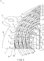
- FIG. 3 is a perspective view illustrating a part of the stator 1P, from the other end surface 10b side (welding side of each coil segment) of the stator core 10.
- the rotary electric machine 1 is configured as a permanent magnet type rotary electric machine, for example.
- the rotary electric machine 1 includes the stator 1P and the rotor 1Q arranged in the field space of the stator 1P.
- the field space of the embodiment is the space where the magnetic field is generated by the stator 1P.
- axial direction a direction of extension of the central axis C of the rotary electric machine 1
- circumferential direction a direction of rotation around the central axis C
- radial direction a direction orthogonal to the axial and circumferential directions
- the stator 1P comprises a stator core 10, and a plurality of stator coils 20 attached to the stator core 10.
- the stator core 10 includes a laminated body with a plurality of circular-shaped electromagnetic steel plates formed of magnetic material such as silicon steel which are laminated concentrically with respect to the central axis C.
- the electromagnetic steel plates are connected to each other by welding multiple locations on the outer periphery of the laminated body.
- the stator core 10 has an inner peripheral surface 10c facing the rotor 1Q in the inner radial direction, and an outer peripheral surface 10c facing the rotor 1Q supported by a casing (not shown) in the outer radial direction.
- the stator core 10 has one end surface 10a located at one end in the axial direction, and another end surface 10d located at the other end in the axial direction.
- the one end surface 10a and the other end surface 10b are orthogonal to the central axis C, respectively.
- the stator core 10 includes a cylindrical yoke 12 located in the outer radial direction, and a plurality of (for example, 48) of teeth 11 extending in the radial direction of the stator core 10 from the yoke 12 in the circumferential direction of the stator core 10 at regular intervals.
- a slot 13 is provided between adjacent teeth 11 in the circumferential direction of the stator core 10.
- 48 slots 13 extend in the radial direction of the stator core 10 between the adjacent teeth 11 and are evenly spaced from each other in the circumferential direction of the stator core 10.
- the slots 13 penetrate axially from one end surface 10a to the other end surface 10b of the stator core 10.
- the slot 13 is open on the inner surface 10c of the stator core 10.
- the stator coil 20 includes a flat conductor with a rectangular cross-section.
- the long side of the stator coil 20 faces the radial direction of the stator core 10 in the slot 13.
- the stator coil 20 is formed of copper or aluminum with sufficient conductivity.
- the stator coil 20 includes a first coil end 20a ( FIG. 2 ) extending axially outward from one end surface 10a of the stator core 10, and a second coil end 20b ( FIG. 3 ) extending axially outward from the other end surface 10b of the stator core 10. That is, in the stator coil 20, the part extending outward from the end surface of the stator core 10 and crossing between different slots 13 corresponds to the first coil end 20a or the second coil end 20b.
- the stator coil 20 includes current input outlet wires at one end and neutral wires connected to each other at the other end.
- the stator coil 20 is placed in the slot 13 of the stator core 10 in a distributed arrangement.
- the stator coil 20 includes a plurality of coil segments (First coil segment 21 to seventh coil segment 27) formed of flat conductor, bonded in series.
- the coil segment integrally includes a first linear part and a second linear part, which are placed in different slots 13, and a bridge part connecting the first linear part and the second linear part in one end surface 10a side in the axial direction of the stator core 10.
- the multiple coil segments are bonded in series via weld beads 28 on the other end surface 10b side of the stator core 10.
- the joint surface of coil segments is, for example, powder coated, or covered with an insulating material such as varnish to ensure electrical insulation.
- the surfaces (sides) other than the bonding surfaces of coil segments are covered with an insulating film, such as enamel, to ensure electrical insulation.
- the coil segments arranged in the same slot 13 are packaged integrally by insulating paper 29 to ensure electrical insulation.
- the first stator coil 20 of each phase (three phases: U, V, and W) includes, a first coil segment 21 inserted into an area 1T positioned radially outermost in each slot 13 ( FIG. 1 ), which is one lane of the concentric circle of the stator core 10 ( FIGS.
- a fifth coil segment 25 inserted across an area 2T (lane 2) and an area 3T (lane 3) of each slot 13
- a sixth coil segment 26 inserted across an area 4T (lane 4) and an area 5T (lane 5) of each slot 13
- a seventh coil segment 27 inserted across an area 6T (lane 6) and an area 7T (lane 7) of each slot 13
- a third coil segment 23 inserted into an area 8T (lane 8) positioned radially innermost in each slot 13, connected in series in the order stated above.
- the second stator coil 20 of each phase includes a second coil segment 22, fifth coil segment 25, sixth coil segment 26, and seventh coil segment 27, and a fourth coil segment 24 inserted into an area 8T (innermost lane 8) of each slot 13, connected in series in the order stated above.
- the second stator coil 20 of each phase is electrically connected in parallel with the first stator coil 20.
- FIG. 4 is a perspective view illustrating the first coil segment 21 and the second coil segment 22 separately, disposed in the outermost area 1T (lane 1) of the slot 13.
- FIG. 5 is a plan view illustrating the first coil segment 21 and the second coil segment 22 separately, disposed in the outermost area 1T (lane 1) (plan view of FIG. 4 from the axial direction).
- FIG. 6 is a side view illustrating the first coil segment 21 and the second coil segment 22 in the area 1T (lane 1) of the slot 13, viewed from the radial outer side of the stator core 10. With reference to FIGS. 4 to 6 , among the coil segments of the stator coil 20, the first coil segment 21 and the second coil segment 22 arranged in the outermost peripheral area 1T (lane 1) of the slot 13 will be explained.
- the first coil segment 21 and the second coil segment 22 are arranged in the radially outermost side of the coil segments (between the first coil segment 21 and the seventh coil segment 27) arranged in the radial direction of the stator core 10 in the slot 13. That is, in the area 1T (lane 1) of the slot 13, any of a first linear part 21P or a second linear part 21Q of the first coil segment 21, or a first linear part 22P or a second linear part 22Q of the second coil segment 22 is placed.
- the first linear part 22P and the second linear part 22Q of the second coil segment 22 are disposed in different slots 13 in a manner to sandwich the first linear part 21P or the second linear part 21Q of the first coil segment 21 from both sides of the circumference of the stator core 10.
- the second coil segment 22 is longer in the circumferential direction of the stator core 10 than the first coil segment 21.
- the first linear part 21P of the first coil segment 21 is located in the area 1T of the slot 13, and the second linear part 22Q is located in the area 1T of the other slot 13, which is located several slots (for example, 17 slots) apart in the circumferential direction.
- the bride part 21R of the first coil segment 21 extends along the circumferential direction of the stator core 10 from an extension end of the first linear part 21P to an extension end of the second linear part 21Q while being distant from the one end surface 10a.
- the first linear part 22P of the second coil segment 22 is located in the area 1T of the slot 13 next to the second linear part 21P of the first coil segment 21 in the opposite side of the second linear part 21Q.
- the second linear part 22Q of the second coil segment 22 is located in the area 1T of the slot 13 next to the second linear part 21Q of the first coil segment 21 in the opposite side of the first linear part 21P. That is, the first linear part 21P and the second linear part 21Q of the first coil segment 21 are located between the first linear part 21P and the second linear part 22Q of the second coil segment 22, and are sandwiched between the first linear part 22P and the second linear part 22Q of the second coil segment 22 from both sides in the circumferential direction.
- the bridge part 22R of the second coil segment 22 extends from the extension end of the first linear part 22P to the extension end of the second linear part 22Q along the circumferential direction of the stator core 10 while being distant from the one end surface 10a.
- the bridge part 22R is disposed radially outwardly with respect to the bridge part 21R of the first coil segment 21.
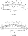
- FIG. 6A is a schematic side view illustrating the first coil segment
- FIG. 6B is a schematic side view illustrating the second coil segment.
- the bridge part 21R of the first coil segment 21 includes a first bridge section L1 and a second bridge section L2.
- the first bridge section L1 extends in the circumferential direction of the stator core 10 toward the second linear part 21Q through a first curving part 21s which is bent to the side of the second linear part 21Q from the first linear part 21P of the first coil segment 21.
- the first bridge section L1 is inclined by a first inclination angle ⁇ 1 ( ⁇ 0°, 180°) in the direction away from the one end surface 10a in the axial direction with respect to a flat surface parallel to the one end surface 10a of the stator core 10.
- the first bridge section L1 has a first bending part 21t which decreases the inclination angle with respect to the one end surface 10a in the middle way extending to the second linear part 21Q.
- the first bridge section L1 includes a first inclined section L1a extending from the first curving part 21S to the first bending part 21t at the first inclination angle ⁇ 1, and a second inclined section L1b extending from the first bending part 21t to the extension end of the first bridge section L1 (top curving part 21W which will be described later) at a second inclination angle ⁇ 2 which is smaller than the first inclination angle ⁇ 1 ( ⁇ 2 ⁇ 1, ⁇ 2 ⁇ 0°, 180°).
- the bending part in the first bridge section L1 is a part of the first bending part 21t, but it is not limited thereto, and there may be N bending parts in N positions where N is two or more.
- the Nth bending part that is relatively far from the first curving part 21S is set to have smaller inclination angle with respect to the one end surface 10a than is the N-1 part that is relatively close to the first curving part 21S.
- the second bridge section L2 extends in the circumferential direction of the stator core 10 toward the first linear part 21P through a second curving part 21u which is bent from the extension end of the second linear part 21Q of the first coil segment 21 to the outside of the stator core 10 in the radial direction.
- the second bridge section L2 is located radially outward that is the first bridge section L1.
- the second bridge section L2 is inclined by a third inclination angle ⁇ 3 ( ⁇ 0°, 180°) in the direction away from the one end surface 10a in the axial direction with respect to a flat surface parallel to the one end surface 10a of the stator core 10.
- the second bridge section L2 includes a second bending part 21v which decreases the inclination angle with respect to the one end surface 10a in a middle way to the first linear part 21P. That is, the second bridge section L2 includes a third inclined section L2a extending from the second curving part 21u to the second bending part 21v at an inclined angle ⁇ 3, and a fourth inclined section L2b extending from the second bending part 21v to the extension end of the second bridge section L2 (top curving part 21W) at an inclination angle ⁇ 4 which is smaller than the third inclination angle ⁇ 3 ( ⁇ 4 ⁇ 3, ⁇ 4 ⁇ 0°, 180°).
- the third inclination angle ⁇ 3 may be common to or different from the first inclination angle ⁇ 1.
- the fourth inclination angle ⁇ 4 may be common to or different from the second inclination angle ⁇ 2.
- the bending part in the second bridge section L2 is a part of the second bending part 21v, but it is not limited thereto, and N bending parts may be disposed in N positions where N is two or more.
- the Nth bending part that is relatively far away from the second curving part 21u is set to have the inclination angle with respect to the one end surface 10a smaller than is the bending part of the N-1th bending part, which is relatively close to the second curving part 21u.
- the first bridge section L1 is connected to the second bridge section L2 via a first connection part 21w, which is bent or inclined in the radial direction.
- the first connection part 21W is positioned in the middle between the first linear part 21P and the second linear part 21Q in the circumferential direction, that is, the first connection part 21W is positioned between the first bridge section L1 and the second bridge section L2 to connect the first bridge section L1 and the second bridge section L2 together.
- the first connection part 21W forms the top part (top curving part) located in the bridge part 21R to be most distant in the axial direction from the one end surface 10a. In this example, the first connecting part 21W extends approximately parallel to the one end surface 10a.
- the bridge part 22R of the second coil segment 22 includes a third bridge section L3 and a fourth bridge section L4.
- the third bridge section L3 extends in the circumferential direction toward the second linear part 22Q through a third curving part 22s which is greatly bent from the first linear part 22P of the second coil segment 22 radially outwardly than is the shape of the second curving part 21u.
- the third bridge section L3 is positioned radially outside the second bridge section L2.
- the third bridge section L3 is inclined by a fifth inclination angle ⁇ 5 ( ⁇ 0°, 180°) in the direction away from the one end surface 10a in the axial direction with respect to a flat surface parallel to the one end surface 10a of the stator core 10.
- the third bridge section L3 has a first bending part 22t which decreases the inclination angle with respect to the one end surface 10a in the middle way extending to the second linear part 22Q. That is, the third bridge section L3 includes a first inclined section L3a extending from the third curving part 22S to the third bending part 22t at the fifth inclination angle ⁇ 5, and a second inclined section L3b extending from the third bending part 22t to the extension end of the third bridge section L3 (top curving part 22W which will be described later) at a sixth inclination angle ⁇ 6 which is smaller than the fifth inclination angle ⁇ 5 ( ⁇ 6 ⁇ 5, ⁇ 6 ⁇ 0°, 180°).
- the third bridge section L3 is positioned radially outward with respect to the first bridge section L1 of the first coil segment 21 to be opposed to the first bridge section L1 with a gap therebetween.
- the fourth bridge section L4 extends in the circumferential direction toward the first linear part 22P through a fourth curving part 22u which is greatly bent from the second linear part 22Q of the second coil segment 22 radially outwardly than is the shape of the third curving part 22s.
- the fourth bridge section L4 is positioned radially outside the third bridge section L3.
- the fourth bridge section L4 is inclined by a seventh inclination angle ⁇ 7 ( ⁇ 0°, 180°) in the direction away from the one end surface 10a in the axial direction with respect to a flat surface parallel to the one end surface 10a of the stator core 10.
- the fourth bridge section L4 has a fourth bending part 22v which decreases the inclination angle with respect to the one end surface 10a in the middle way extending to the first linear part 22P. That is, the fourth bridge section L4 includes a third inclined section L4a extending from the fourth curving part 22u to the fourth bending part 22v at the seventh inclination angle ⁇ 7, and a fourth inclined section L4b extending from the fourth bending part 22v to the extension end of the fourth bridge section L4 (top curving part 22W) at an eighth inclination angle ⁇ 8 which is smaller than the seventh inclination angle ⁇ 7 ( ⁇ 8 ⁇ 7, ⁇ 8 ⁇ 0°, 180°).
- the seventh inclination angle ⁇ 7 may be common to or different from the fifth inclination angle ⁇ 5.
- the eighth inclination angle ⁇ 8 may be common to or different from the sixth inclination angle ⁇ 6.
- the fourth bridge section L4 of the second coil segment 22 is positioned radially outward with respect to the second bridge section L2 of the first coil segment 21 to be opposed to the second bridge section L2 with a gap therebetween.
- the third bridge section L3 is connected to the fourth bridge section L4 via a second connection part 22w, which is bent or inclined in the radial direction.
- the second connection part 22W is positioned in the middle between the first linear part 22P and the second linear part 22Q in the circumferential direction, that is, the second connection part 22W is positioned between the third bridge section L3 and the fourth bridge section L4 to connect the third bridge section L3 and the fourth bridge section L4 together.
- the second connection part 22W forms the top part (top curving part) located in the bridge part 22R to be most distant in the axial direction from the one end surface 10a. In this example, the second connection part 22W extends approximately parallel to the one end surface 10a.
- the second connection part 22W and the aforementioned first connection part 21W of the first coil segment 21 are located at the common height position in the axial direction with respect to the one end surface 10a.
- the second connection part 22W is positioned outside the first connection part 21W in the radial direction to be opposed to the first connection part 21W at an interval.
- the bending parts in the third bridge section L3 and the fourth bridge section L4 of the second coil segment are a third bending part 22t and a fourth bending part 22v, respectively, but they are not limited thereto, and N bending parts may be disposed in N positions where N is two or more.
- the Nth bending part that is relatively far away from the third curving part 22S or the fourth curving part 22u is set to have the inclination angle with respect to the one end surface 10a smaller than is the bending part of the N-1th bending part, which is relatively close to the third curving part 22S or the fourth curving part 22u.
- the rotor 1Q includes a cylindrical rotor core 30, shaft 31 installed in the center of the rotor core 30 to be rotated around the central axis C, and a plurality of permanent magnets 3 arranged in a circumferential direction at the periphery of the rotor core 30.
- the rotor core 30 includes circular electromagnetic steel plates with magnetism, such as silicon steel, laminated concentrically about the central axis C.
- the electromagnetic steel plates are connected by welding at multiple locations on the outer periphery while laminated to each other.
- the rotor core 30 is separated from the inner peripheral surface 10c of the stator core 10 by a small gap (air gap), and is arranged coaxially with the central axis C of the stator core 10.
- the outer peripheral surface of the rotor core 30 is opposed to the tip end surface of the teeth 11 corresponding to the inner peripheral surface 10c of the stator core 10 with a small gap (air gap) therebetween.
- the rotor core 30 has one first inner hole 30a penetrating coaxially with the central axis C and a plurality of second inner holes 30b aligned in the circumferential direction at the outer periphery and penetrating in the axial direction.
- the shaft 31 is formed in the shape of a cylinder, and is inserted and fitted into the first inner hole 30a of the rotor core 30.
- the shaft 31 extends coaxially with the central axis C of the rotor core 30.
- the shaft 31 rotates together with the rotor core 30, and transmits rotational power to a wheel or the like, which is not shown, through connecting gears, etc.
- the permanent magnets 32 extend over the entire axial length of the rotor core 30, and are arranged at predetermined intervals in the circumferential direction of the rotor core 30.
- the permanent magnets 32 are rectangular in cross section, and formed in a bar shape extending in the axial direction.
- the bridge part 21R of the first coil segment 21 and the bridge part 22R of the second coil segment 22 are adjacent to each other in the radial direction of the stator core 10 while they are distant from each other in the radial direction of the stator core 10, and thus, they do not interfere with each other. That is, the third bridge section L3 and the fourth bridge section L4 of the second coil segment 22 are positioned more radially outside of the stator core 10 than is the second bridge section L2 of the first coil segment 21, with a gap therebetween.
- the bridge parts 21R and 22R adjacent to each other in the radial direction of the stator core 10 do not vertically overlap with each other in the axial direction of the stator core 10.
- the projection height of the stator core 10 in the axial direction can be suppressed by sufficiently bending or curving the bridge parts 21R and 22R with respect to the one end surface 10a of the stator core 10 independently without interference therebetween.
- the first coil segment 21 and the second coil segment 22 can set the axial projection length of the first coil end 20a from the one end surface 10a of the stator core 10 to be relatively short.
- the bridge parts 21R and 22R of the first and second coil segments 21 and 22 may include first and second bending parts 21t and 21v and third and fourth bending parts 22t and 22v which shallow the inclination angle with respect to the one end surface 10a of the stator core 10 in order to reduce a gap G formed in the axis direction between the bridge parts 21R and 22R of the first and second coil segments adjacent in the circumferential direction of the stator core 10.
- the bridge parts 21R and 22R with smaller inclination angle with respect to the one end surface 10a with the first and second bending parts 21t and 21v and third and fourth bending parts 22t and 22v are adjacent at a relatively small angle with respect to the other first and second coil segments adjacent to each other in the circumferential direction of the stator core 10.
- the first coil segment 21 and the second coil segment 22 can set the axial projection length of the first coil end 20a from the one end surface 10a of the stator core 10 to be relatively short.
- the stator 1P of the rotary electric machine 1 can be miniaturized, and the rotary electric machine 1 including the stator 1P can be miniaturized as well.
- the bridge part 21R of the first coil segment 21 includes, between the first bridge section L1 and the second bridge section L2, the first connection part 21w bent or curved in the radial direction.
- the bridge part 22R of the second coil segment 22 include, between the third bridge section L3 and the fourth bridge section L4, the second connection part 22w bent or curved in the radial direction and opposed to the first connection part 21w with a gap therebetween.
- the first coil segment 21 and the second coil segment 22 can further suppress the axial projection length of the first coil end 20a from the one end surface 10a of the stator core 10.
- the stator 1P of the rotary electric machine 1 and the rotary electric machine 1 including the stator 1P can be miniaturized.
- the number of coil turns, and the number of coil segments can be increased or decreased as appropriate, without being limited to the numbers of the above-mentioned embodiment.
- the rotor and the rotary electric machine of the embodiment are not limited to permanent magnet field motors, but may be applied to wound field rotary electric machines, and induction rotary electric machines.
- the dimensions, material, shape, etc., of the rotor are not limited to those of the embodiment described above, but may be changed in various ways according to the design. Specifically, instead of the structure in which eight coil segments are installed in each slot 13 of the stator core 10 as in the embodiment, a structure in which six or fewer or ten or more coil segments are installed in each slot may be adopted.
Landscapes
- Engineering & Computer Science (AREA)
- Power Engineering (AREA)
- Windings For Motors And Generators (AREA)
Abstract
Description
- Embodiments of the present application relate generally to a stator of a rotary electric machine and a rotary electric machine.
- Rotary electric machines include a cylindrical stator and a rotor arranged rotatably in a field space of the stator. The stator includes a stator core including multi-layered annular electromagnetic steel plates, and a stator coil formed of a flat conductor and attached to the stator core. Coils formed of a plurality of coil segments bonded together in series include coil ends protruding outward from both end surfaces of the stator core in the axial direction. In recent years, demand for smaller stators of rotary electric machines is high.
- Patent Literature 1:
JP 2016-152753 A - Embodiments of the present application present a stator of a rotary electric machine which will miniaturize a stator core, and a rotary electric machine with such a stator.
- According to an embodiment, a stator of rotary electric machine comprises a stator core including a yoke, a plurality of teeth, one end surface positioned at one end of an axial direction, and other end surface positioned in the other end of the axial direction, the stator core forming slots each extending in a radial direction between the teeth adjacent to each other; and a plurality of stator coils each of which is structured by joining a plurality of coil segments to each other, each of the coil segments being formed of a rectangular conductor and including a first linear part and a second linear part positioned separately in the slots, and a bridge part connecting the first linear part and the second linear part on a side of the one end surface of the stator core.
- The coil segments include a first coil segment including a first linear part positioned outermost in the radial direction among the coil segments arranged in the radial direction in the slot, a second linear part positioned outermost in the radial direction among the coil segments in a different slot, and a bridge part, and
a second coil segment including a first linear part positioned outermost in the radial direction among the coil segments in the slot adjacent to the first linear part of the first coil segment in the opposite side of the second linear part of the first coil segment, a second linear part positioned outermost in the radial direction among the coil segments in the slot adjacent to the second linear part of the first coil segment in the opposite side of the first linear part of the first coil segment, and a bridge part. - The bridge part of the first coil segment includes a first bridge section extending in a circumferential direction of the stator core toward the second linear part through a first curving part curving from the first linear part of the first coil segment to the second linear part side, inclining outward in the axial direction at a first inclination angle with respect to a flat surface parallel to the one end surface, the first bridge section including a first bending part in a halfway through the circumferential direction forming a second inclination angle as the angle inclining with respect to the flat surface parallel to the one end surface, which is smaller than the first inclination angle, and
- a second bridge section extending in the circumferential direction toward the first linear part on the outside in the radial direction than is the first bridge section through a second curving part curving outward in the radial direction from the second linear part of the first coil segment, inclining outward in the axial direction at a third inclination angle with respect to a flat surface parallel to the one end surface, the second bridge section including a second bending part in a halfway through the circumferential direction forming a fourth inclination angle as the angle inclining with respect to the one end surface, which is smaller than the third inclination angle, and
- the bridge part of the second coil segment includes a third bridge section extending in the circumferential direction toward the second linear part of the second coil segment on the outside in the radial direction than is the second bridge section through a third curving part curving outward in the radial direction greater than is the second curving part from the first linear part of the second coil segment, inclining outward in the axial direction at a fifth inclination angle with respect to a flat surface parallel to the one end surface, the third bridge section including a third bending part in a halfway through the circumferential direction forming a sixth inclination angle as the angle inclining with respect to a flat surface parallel to the one end surface, which is smaller than the fifth inclination angle, and
- a fourth bridge section extending in the circumferential direction toward the first linear part of the second coil segment in the outside of the radial direction than is the third bridge section through a fourth curving part curving outward in the radial direction greater than is the third curving part from the second linear part of the second coil segment, inclining outward in the axial direction at a seventh inclination angle with respect to a flat surface parallel to the one end surface, the fourth bridge section including a fourth bending part forming an eighth inclination angle as the angle inclining with respect to a flat surface parallel to the one end surface, which is smaller than the seventh inclination angle.
- According to an embodiment, a rotary electric machine comprises the aforementioned stator and a rotor positioned in a field space of the stator.
-
-
FIG. 1 is a lateral cross-sectional view of a rotary electric machine of an embodiment. -
FIG. 2 is a perspective view illustrating a part of a stator of the rotary electric machine from one end surface side (non-welding side of each coil segment) of the stator core. -
FIG. 3 is a perspective view illustrating a part of the stator from the other end surface side (welding side of each coil segment) of the stator core. -
FIG. 4 is a perspective view illustrating a first coil segment and a second coil segment separately, arranged in the outermost part of slots. -
FIG. 5 is a plan view of the first coil segment and the second coil segment separately, arranged in the outermost part of slots (plan view ofFIG. 4 viewed from the axial direction). -
FIG. 6A is a side view schematically illustrating the first coil segment. -
FIG. 6B is a side view schematically illustrating the second coil segment. -
FIG. 7 is a side view illustrating multiple pairs of the first coil segments and the second coil segments arranged in the outermost part of the slots. - Best Mode for Carrying Out the Invention Embodiments of the present invention will be described below with reference to the accompanying drawings.
- Note that, embodiments are merely examples, and the contents of the embodiments do not limit the scope of the invention. Modifications which can easily be conceived by a person having an ordinary skill are naturally encompassed in the scope of the invention. For easier understanding of the description, size, shape, and the like of each element may be changed from the actual implementation while being only schematically depicted in the figures.
- With reference to
FIGS. 1 to 6 , a rotaryelectric machine 1 and astator 1P and arotor 1Q of the rotaryelectric machine 1 of an embodiment will be described. -
FIG. 1 is a cross-sectional view of the rotaryelectric machine 1 of the embodiment.FIG. 2 is a perspective view illustrating a part of thestator 1P of the rotary electric machine, from oneend surface 10a side (non-welding side of each coil segment) of astator core 10.FIG. 3 is a perspective view illustrating a part of thestator 1P, from theother end surface 10b side (welding side of each coil segment) of thestator core 10. - As shown in
FIG. 1 , the rotaryelectric machine 1 is configured as a permanent magnet type rotary electric machine, for example. The rotaryelectric machine 1 includes thestator 1P and therotor 1Q arranged in the field space of thestator 1P. The field space of the embodiment is the space where the magnetic field is generated by thestator 1P. - In the following description, a direction of extension of the central axis C of the rotary
electric machine 1 is referred to as axial direction, a direction of rotation around the central axis C as circumferential direction, and direction orthogonal to the axial and circumferential directions as radial direction. - The
stator 1P comprises astator core 10, and a plurality ofstator coils 20 attached to thestator core 10. - The
stator core 10 includes a laminated body with a plurality of circular-shaped electromagnetic steel plates formed of magnetic material such as silicon steel which are laminated concentrically with respect to the central axis C. The electromagnetic steel plates are connected to each other by welding multiple locations on the outer periphery of the laminated body. Thestator core 10 has an innerperipheral surface 10c facing therotor 1Q in the inner radial direction, and an outerperipheral surface 10c facing therotor 1Q supported by a casing (not shown) in the outer radial direction. As shown inFIGS. 2 and3 , thestator core 10 has oneend surface 10a located at one end in the axial direction, and anotherend surface 10d located at the other end in the axial direction. The oneend surface 10a and theother end surface 10b are orthogonal to the central axis C, respectively. - As shown in
FIG. 1 , thestator core 10 includes acylindrical yoke 12 located in the outer radial direction, and a plurality of (for example, 48) ofteeth 11 extending in the radial direction of thestator core 10 from theyoke 12 in the circumferential direction of thestator core 10 at regular intervals. Aslot 13 is provided betweenadjacent teeth 11 in the circumferential direction of thestator core 10. 48slots 13 extend in the radial direction of thestator core 10 between theadjacent teeth 11 and are evenly spaced from each other in the circumferential direction of thestator core 10. Theslots 13 penetrate axially from oneend surface 10a to theother end surface 10b of thestator core 10. Theslot 13 is open on theinner surface 10c of thestator core 10. - As shown in
FIG. 1 , thestator coil 20 includes a flat conductor with a rectangular cross-section. The long side of thestator coil 20 faces the radial direction of thestator core 10 in theslot 13. Thestator coil 20 is formed of copper or aluminum with sufficient conductivity. Thestator coil 20 includes afirst coil end 20a (FIG. 2 ) extending axially outward from oneend surface 10a of thestator core 10, and asecond coil end 20b (FIG. 3 ) extending axially outward from theother end surface 10b of thestator core 10. That is, in thestator coil 20, the part extending outward from the end surface of thestator core 10 and crossing betweendifferent slots 13 corresponds to thefirst coil end 20a or thesecond coil end 20b. Thestator coil 20 includes current input outlet wires at one end and neutral wires connected to each other at the other end. - As shown in
FIG. 2 , thestator coil 20 is placed in theslot 13 of thestator core 10 in a distributed arrangement. In the embodiment, there are twostator coils 20 connected in parallel and receiving current in phase U, twostator coils 20 connected in parallel and receiving current in phase V, and twostator coils 20 connected in parallel and receiving current in phase W. That is, the rotaryelectric machine 1 is driven by a three-phase AC power supply of U-phase, V-phase, and W-phase. - As shown in
FIGS. 2 and3 , thestator coil 20 includes a plurality of coil segments (First coil segment 21 to seventh coil segment 27) formed of flat conductor, bonded in series. The coil segment integrally includes a first linear part and a second linear part, which are placed indifferent slots 13, and a bridge part connecting the first linear part and the second linear part in oneend surface 10a side in the axial direction of thestator core 10. As inFIG. 3 , the multiple coil segments are bonded in series viaweld beads 28 on theother end surface 10b side of thestator core 10. In thestator coil 20, the joint surface of coil segments is, for example, powder coated, or covered with an insulating material such as varnish to ensure electrical insulation. As inFIG. 1 , the surfaces (sides) other than the bonding surfaces of coil segments are covered with an insulating film, such as enamel, to ensure electrical insulation. Furthermore, the coil segments arranged in thesame slot 13 are packaged integrally by insulatingpaper 29 to ensure electrical insulation. - As in
FIGS. 1 to 3 , thefirst stator coil 20 of each phase (three phases: U, V, and W) includes, afirst coil segment 21 inserted into anarea 1T positioned radially outermost in each slot 13 (FIG. 1 ), which is one lane of the concentric circle of the stator core 10 (FIGS. 2 and3 ), afifth coil segment 25 inserted across anarea 2T (lane 2) and anarea 3T (lane 3) of eachslot 13, asixth coil segment 26 inserted across anarea 4T (lane 4) and anarea 5T (lane 5) of eachslot 13, aseventh coil segment 27 inserted across anarea 6T (lane 6) and an area 7T (lane 7) of eachslot 13, and athird coil segment 23 inserted into anarea 8T (lane 8) positioned radially innermost in eachslot 13, connected in series in the order stated above. - As in
FIGS. 1 to 3 , thesecond stator coil 20 of each phase includes asecond coil segment 22,fifth coil segment 25,sixth coil segment 26, andseventh coil segment 27, and afourth coil segment 24 inserted into anarea 8T (innermost lane 8) of eachslot 13, connected in series in the order stated above. Thesecond stator coil 20 of each phase is electrically connected in parallel with thefirst stator coil 20. -
FIG. 4 is a perspective view illustrating thefirst coil segment 21 and thesecond coil segment 22 separately, disposed in theoutermost area 1T (lane 1) of theslot 13.FIG. 5 is a plan view illustrating thefirst coil segment 21 and thesecond coil segment 22 separately, disposed in theoutermost area 1T (lane 1) (plan view ofFIG. 4 from the axial direction).FIG. 6 is a side view illustrating thefirst coil segment 21 and thesecond coil segment 22 in thearea 1T (lane 1) of theslot 13, viewed from the radial outer side of thestator core 10. With reference toFIGS. 4 to 6 , among the coil segments of thestator coil 20, thefirst coil segment 21 and thesecond coil segment 22 arranged in the outermostperipheral area 1T (lane 1) of theslot 13 will be explained. - As in
FIG. 4 , thefirst coil segment 21 and thesecond coil segment 22 are arranged in the radially outermost side of the coil segments (between thefirst coil segment 21 and the seventh coil segment 27) arranged in the radial direction of thestator core 10 in theslot 13. That is, in thearea 1T (lane 1) of theslot 13, any of a firstlinear part 21P or a secondlinear part 21Q of thefirst coil segment 21, or a firstlinear part 22P or a secondlinear part 22Q of thesecond coil segment 22 is placed. The firstlinear part 22P and the secondlinear part 22Q of thesecond coil segment 22 are disposed indifferent slots 13 in a manner to sandwich the firstlinear part 21P or the secondlinear part 21Q of thefirst coil segment 21 from both sides of the circumference of thestator core 10. In other words, thesecond coil segment 22 is longer in the circumferential direction of thestator core 10 than thefirst coil segment 21. - As in
FIGS. 4 and5 , the firstlinear part 21P of thefirst coil segment 21 is located in thearea 1T of theslot 13, and the secondlinear part 22Q is located in thearea 1T of theother slot 13, which is located several slots (for example, 17 slots) apart in the circumferential direction. Thebride part 21R of thefirst coil segment 21 extends along the circumferential direction of thestator core 10 from an extension end of the firstlinear part 21P to an extension end of the secondlinear part 21Q while being distant from the oneend surface 10a. - The first
linear part 22P of thesecond coil segment 22 is located in thearea 1T of theslot 13 next to the secondlinear part 21P of thefirst coil segment 21 in the opposite side of the secondlinear part 21Q. The secondlinear part 22Q of thesecond coil segment 22 is located in thearea 1T of theslot 13 next to the secondlinear part 21Q of thefirst coil segment 21 in the opposite side of the firstlinear part 21P. That is, the firstlinear part 21P and the secondlinear part 21Q of thefirst coil segment 21 are located between the firstlinear part 21P and the secondlinear part 22Q of thesecond coil segment 22, and are sandwiched between the firstlinear part 22P and the secondlinear part 22Q of thesecond coil segment 22 from both sides in the circumferential direction. - The
bridge part 22R of thesecond coil segment 22 extends from the extension end of the firstlinear part 22P to the extension end of the secondlinear part 22Q along the circumferential direction of thestator core 10 while being distant from the oneend surface 10a. Thebridge part 22R is disposed radially outwardly with respect to thebridge part 21R of thefirst coil segment 21. -
FIG. 6A is a schematic side view illustrating the first coil segment, andFIG. 6B is a schematic side view illustrating the second coil segment. - As in
FIGS. 4 ,5 , and6A , thebridge part 21R of thefirst coil segment 21 includes a first bridge section L1 and a second bridge section L2. - The first bridge section L1 extends in the circumferential direction of the
stator core 10 toward the secondlinear part 21Q through a firstcurving part 21s which is bent to the side of the secondlinear part 21Q from the firstlinear part 21P of thefirst coil segment 21. The first bridge section L1 is inclined by a first inclination angle θ1 (≠0°, 180°) in the direction away from the oneend surface 10a in the axial direction with respect to a flat surface parallel to the oneend surface 10a of thestator core 10. The first bridge section L1 has afirst bending part 21t which decreases the inclination angle with respect to the oneend surface 10a in the middle way extending to the secondlinear part 21Q. That is, the first bridge section L1 includes a first inclined section L1a extending from the firstcurving part 21S to the first bendingpart 21t at the first inclination angle θ1, and a second inclined section L1b extending from the first bendingpart 21t to the extension end of the first bridge section L1 (top curving part 21W which will be described later) at a second inclination angle θ2 which is smaller than the first inclination angle θ1 (θ2<θ1, θ2≠0°, 180°). - In the present embodiment, the bending part in the first bridge section L1 is a part of the first bending
part 21t, but it is not limited thereto, and there may be N bending parts in N positions where N is two or more. In that case, the Nth bending part that is relatively far from the firstcurving part 21S is set to have smaller inclination angle with respect to the oneend surface 10a than is the N-1 part that is relatively close to the firstcurving part 21S. Furthermore, a structure in which the Nth bending part, which is the farthest from the firstcurving part 21S, is set to an inclination angle θ = zero, and the top of the bending part extends substantially parallel to the oneend surface 10a may be adopted. - The second bridge section L2 extends in the circumferential direction of the
stator core 10 toward the firstlinear part 21P through a secondcurving part 21u which is bent from the extension end of the secondlinear part 21Q of thefirst coil segment 21 to the outside of thestator core 10 in the radial direction. The second bridge section L2 is located radially outward that is the first bridge section L1. The second bridge section L2 is inclined by a third inclination angle θ3 (≠0°, 180°) in the direction away from the oneend surface 10a in the axial direction with respect to a flat surface parallel to the oneend surface 10a of thestator core 10. The second bridge section L2 includes asecond bending part 21v which decreases the inclination angle with respect to the oneend surface 10a in a middle way to the firstlinear part 21P. That is, the second bridge section L2 includes a third inclined section L2a extending from the secondcurving part 21u to thesecond bending part 21v at an inclined angle θ3, and a fourth inclined section L2b extending from thesecond bending part 21v to the extension end of the second bridge section L2 (top curving part 21W) at an inclination angle θ4 which is smaller than the third inclination angle θ3 (θ4<θ3, θ4≠0°, 180°). - The third inclination angle θ3 may be common to or different from the first inclination angle θ1. The fourth inclination angle θ4 may be common to or different from the second inclination angle θ2. In the present embodiment, θ1=θ3 and θ2=θ4.
- In the present embodiment, the bending part in the second bridge section L2 is a part of the
second bending part 21v, but it is not limited thereto, and N bending parts may be disposed in N positions where N is two or more. In that case, the Nth bending part that is relatively far away from the secondcurving part 21u is set to have the inclination angle with respect to the oneend surface 10a smaller than is the bending part of the N-1th bending part, which is relatively close to the secondcurving part 21u. Furthermore, a structure in which the Nth bending part, which is the farthest from the secondcurving part 21u, is set to an inclination angle θ = zero, and the top part extends substantially parallel to the oneend surface 10a may be adopted. - The first bridge section L1 is connected to the second bridge section L2 via a
first connection part 21w, which is bent or inclined in the radial direction. Thefirst connection part 21W is positioned in the middle between the firstlinear part 21P and the secondlinear part 21Q in the circumferential direction, that is, thefirst connection part 21W is positioned between the first bridge section L1 and the second bridge section L2 to connect the first bridge section L1 and the second bridge section L2 together. Thefirst connection part 21W forms the top part (top curving part) located in thebridge part 21R to be most distant in the axial direction from the oneend surface 10a. In this example, the first connectingpart 21W extends approximately parallel to the oneend surface 10a. - As in
FIGS. 4 ,5 , and6B , thebridge part 22R of thesecond coil segment 22 includes a third bridge section L3 and a fourth bridge section L4. - The third bridge section L3 extends in the circumferential direction toward the second
linear part 22Q through a thirdcurving part 22s which is greatly bent from the firstlinear part 22P of thesecond coil segment 22 radially outwardly than is the shape of the secondcurving part 21u. The third bridge section L3 is positioned radially outside the second bridge section L2. The third bridge section L3 is inclined by a fifth inclination angle θ5 (≠0°, 180°) in the direction away from the oneend surface 10a in the axial direction with respect to a flat surface parallel to the oneend surface 10a of thestator core 10. The third bridge section L3 has afirst bending part 22t which decreases the inclination angle with respect to the oneend surface 10a in the middle way extending to the secondlinear part 22Q. That is, the third bridge section L3 includes a first inclined section L3a extending from the thirdcurving part 22S to thethird bending part 22t at the fifth inclination angle θ5, and a second inclined section L3b extending from thethird bending part 22t to the extension end of the third bridge section L3 (top curving part 22W which will be described later) at a sixth inclination angle θ6 which is smaller than the fifth inclination angle θ5 (θ6<θ5, θ6≠0°, 180°). - The third bridge section L3 is positioned radially outward with respect to the first bridge section L1 of the
first coil segment 21 to be opposed to the first bridge section L1 with a gap therebetween. - The fourth bridge section L4 extends in the circumferential direction toward the first
linear part 22P through a fourthcurving part 22u which is greatly bent from the secondlinear part 22Q of thesecond coil segment 22 radially outwardly than is the shape of the thirdcurving part 22s. The fourth bridge section L4 is positioned radially outside the third bridge section L3. The fourth bridge section L4 is inclined by a seventh inclination angle θ7 (≠0°, 180°) in the direction away from the oneend surface 10a in the axial direction with respect to a flat surface parallel to the oneend surface 10a of thestator core 10. The fourth bridge section L4 has afourth bending part 22v which decreases the inclination angle with respect to the oneend surface 10a in the middle way extending to the firstlinear part 22P. That is, the fourth bridge section L4 includes a third inclined section L4a extending from the fourthcurving part 22u to thefourth bending part 22v at the seventh inclination angle θ7, and a fourth inclined section L4b extending from thefourth bending part 22v to the extension end of the fourth bridge section L4 (top curving part 22W) at an eighth inclination angle θ8 which is smaller than the seventh inclination angle θ7 (θ8<θ7, θ8≠0°, 180°). - The seventh inclination angle θ7 may be common to or different from the fifth inclination angle θ5. The eighth inclination angle θ8 may be common to or different from the sixth inclination angle θ6. In the present embodiment, θ5=θ7 and θ6=θ8. Furthermore, in the present embodiment, θ1=θ5 and θ2=θ6.
- The fourth bridge section L4 of the
second coil segment 22 is positioned radially outward with respect to the second bridge section L2 of thefirst coil segment 21 to be opposed to the second bridge section L2 with a gap therebetween. - As in
FIG. 5 , the third bridge section L3 is connected to the fourth bridge section L4 via asecond connection part 22w, which is bent or inclined in the radial direction. Thesecond connection part 22W is positioned in the middle between the firstlinear part 22P and the secondlinear part 22Q in the circumferential direction, that is, thesecond connection part 22W is positioned between the third bridge section L3 and the fourth bridge section L4 to connect the third bridge section L3 and the fourth bridge section L4 together. Thesecond connection part 22W forms the top part (top curving part) located in thebridge part 22R to be most distant in the axial direction from the oneend surface 10a. In this example, thesecond connection part 22W extends approximately parallel to the oneend surface 10a. - The
second connection part 22W and the aforementionedfirst connection part 21W of thefirst coil segment 21 are located at the common height position in the axial direction with respect to the oneend surface 10a. Thesecond connection part 22W is positioned outside thefirst connection part 21W in the radial direction to be opposed to thefirst connection part 21W at an interval. - In the present embodiment, the bending parts in the third bridge section L3 and the fourth bridge section L4 of the second coil segment are a
third bending part 22t and afourth bending part 22v, respectively, but they are not limited thereto, and N bending parts may be disposed in N positions where N is two or more. In that case, the Nth bending part that is relatively far away from the thirdcurving part 22S or the fourthcurving part 22u is set to have the inclination angle with respect to the oneend surface 10a smaller than is the bending part of the N-1th bending part, which is relatively close to the thirdcurving part 22S or the fourthcurving part 22u. Furthermore, a structure in which the Nth bending part, which is the farthest from the thirdcurving part 22S or the fourthcurving part 22u, is set to an inclination angle θ = zero, and the top part of thebridge part 22R extends substantially parallel to the oneend surface 10a may be adopted. - As in
FIG. 1 , therotor 1Q includes acylindrical rotor core 30,shaft 31 installed in the center of therotor core 30 to be rotated around the central axis C, and a plurality of permanent magnets 3 arranged in a circumferential direction at the periphery of therotor core 30. - The
rotor core 30 includes circular electromagnetic steel plates with magnetism, such as silicon steel, laminated concentrically about the central axis C. The electromagnetic steel plates are connected by welding at multiple locations on the outer periphery while laminated to each other. Therotor core 30 is separated from the innerperipheral surface 10c of thestator core 10 by a small gap (air gap), and is arranged coaxially with the central axis C of thestator core 10. In other words, the outer peripheral surface of therotor core 30 is opposed to the tip end surface of theteeth 11 corresponding to the innerperipheral surface 10c of thestator core 10 with a small gap (air gap) therebetween. Therotor core 30 has one firstinner hole 30a penetrating coaxially with the central axis C and a plurality of secondinner holes 30b aligned in the circumferential direction at the outer periphery and penetrating in the axial direction. - The
shaft 31 is formed in the shape of a cylinder, and is inserted and fitted into the firstinner hole 30a of therotor core 30. Theshaft 31 extends coaxially with the central axis C of therotor core 30. Theshaft 31 rotates together with therotor core 30, and transmits rotational power to a wheel or the like, which is not shown, through connecting gears, etc. Thepermanent magnets 32 extend over the entire axial length of therotor core 30, and are arranged at predetermined intervals in the circumferential direction of therotor core 30. Thepermanent magnets 32 are rectangular in cross section, and formed in a bar shape extending in the axial direction. - In the embodiment structured as above, as in
FIGS. 4 and5 , thebridge part 21R of thefirst coil segment 21 and thebridge part 22R of thesecond coil segment 22 are adjacent to each other in the radial direction of thestator core 10 while they are distant from each other in the radial direction of thestator core 10, and thus, they do not interfere with each other. That is, the third bridge section L3 and the fourth bridge section L4 of thesecond coil segment 22 are positioned more radially outside of thestator core 10 than is the second bridge section L2 of thefirst coil segment 21, with a gap therebetween. Thebridge parts stator core 10 do not vertically overlap with each other in the axial direction of thestator core 10. Therefore, the projection height of thestator core 10 in the axial direction can be suppressed by sufficiently bending or curving thebridge parts end surface 10a of thestator core 10 independently without interference therebetween. As can be understood from the above, thefirst coil segment 21 and thesecond coil segment 22 can set the axial projection length of thefirst coil end 20a from the oneend surface 10a of thestator core 10 to be relatively short. - Furthermore, as in
FIG. 7 , if a plurality of pairs of thefirst coil segments 21 and thesecond coil segments 22 are arranged in the circumferential direction, thebridge parts second coil segments second bending parts fourth bending parts end surface 10a of thestator core 10 in order to reduce a gap G formed in the axis direction between thebridge parts stator core 10. That is, thebridge parts end surface 10a with the first andsecond bending parts fourth bending parts stator core 10. As can be understood from the above, thefirst coil segment 21 and thesecond coil segment 22 can set the axial projection length of thefirst coil end 20a from the oneend surface 10a of thestator core 10 to be relatively short. - With the shortened projection length of the coil ends, the
stator 1P of the rotaryelectric machine 1 can be miniaturized, and the rotaryelectric machine 1 including thestator 1P can be miniaturized as well. - Furthermore, the
bridge part 21R of thefirst coil segment 21 includes, between the first bridge section L1 and the second bridge section L2, thefirst connection part 21w bent or curved in the radial direction. Similarly, thebridge part 22R of thesecond coil segment 22 include, between the third bridge section L3 and the fourth bridge section L4, thesecond connection part 22w bent or curved in the radial direction and opposed to thefirst connection part 21w with a gap therebetween. With such a structure, thefirst coil segment 21 and thesecond coil segment 22 can further suppress the axial projection length of thefirst coil end 20a from the oneend surface 10a of thestator core 10. Thus, thestator 1P of the rotaryelectric machine 1 and the rotaryelectric machine 1 including thestator 1P can be miniaturized. - While certain embodiments have been described, these embodiments have been presented by way of example only, and are not intended to limit the scope of the inventions. Indeed, the novel embodiments described herein may be embodied in a variety of other forms; furthermore, various omissions, substitutions and changes in the form of the embodiments described herein may be made without departing from the spirit of the inventions. The accompanying claims and their equivalents are intended to cover such forms or modifications as would fall within the scope and spirit of the inventions.
- For example, the number of coil turns, and the number of coil segments can be increased or decreased as appropriate, without being limited to the numbers of the above-mentioned embodiment. The rotor and the rotary electric machine of the embodiment are not limited to permanent magnet field motors, but may be applied to wound field rotary electric machines, and induction rotary electric machines. The dimensions, material, shape, etc., of the rotor are not limited to those of the embodiment described above, but may be changed in various ways according to the design. Specifically, instead of the structure in which eight coil segments are installed in each
slot 13 of thestator core 10 as in the embodiment, a structure in which six or fewer or ten or more coil segments are installed in each slot may be adopted. - 1: Rotary electric machine, 1P: Stator, 1Q: Rotor, 10: Stator core, 10a: One end surface, 11: Teeth, 12: Yoke, 13: Slot, 20: Stator coil, 21: First coil segment, 21P: First linear part, 21Q: Second linear part, 21R: Bridge part, 21s: First curving part, 21t: First bending part, 21u: Second curving part, 21v: Second bending part, 21w: First connection part, 22: Second coil segment, 22P: First linear part, 22Q: Second linear part, 22R: Bridge part, 22s: Third curving part, 22t: Third bending part, 22u: Fourth curving part, 22v: Fourth bending part, 22w: Second connection part, L1: First bridge section, L2: Second bridge section, L3: Third bridge section, L4: Fourth bridge section
Claims (3)
- A stator of rotary electric machine; comprising:a stator core including a yoke, a plurality of teeth, one end surface positioned at one end of an axial direction, and other end surface positioned in the other end of the axial direction, the stator core forming slots each extending in a radial direction between the teeth adjacent to each other; anda plurality of stator coils each of which is structured by joining a plurality of coil segments to each other, each of the coil segments being formed of a rectangular conductor and including a first linear part and a second linear part positioned separately in the slots, and a bridge part connecting the first linear part and the second linear part on a side of the one end surface of the stator core, whereinthe coil segments include:a first coil segment including a first linear part positioned outermost in the radial direction among the coil segments arranged in the radial direction in the slot, a second linear part positioned outermost in the radial direction among the coil segments in a different slot, and a bridge part, anda second coil segment including a first linear part positioned outermost in the radial direction among the coil segments in the slot adjacent to the first linear part of the first coil segment in the opposite side of the second linear part of the first coil segment, a second linear part positioned outermost in the radial direction among the coil segments in the slot adjacent to the second linear part of the first coil segment in the opposite side of the first linear part of the first coil segment, and a bridge part, andthe bridge part of the first coil segment includesa first bridge section extending in a circumferential direction of the stator core toward the second linear part through a first curving part curving from the first linear part of the first coil segment to the second linear part side, inclining outward in the axial direction at a first inclination angle with respect to a flat surface parallel to the one end surface, the first bridge section including a first bending part in a halfway through the circumferential direction forming a second inclination angle as the angle inclining with respect to the flat surface parallel to the one end surface, which is smaller than the first inclination angle, anda second bridge section extending in the circumferential direction toward the first linear part on the outside in the radial direction than is the first bridge section through a second curving part curving outward in the radial direction from the second linear part of the first coil segment, inclining outward in the axial direction at a third inclination angle with respect to a flat surface parallel to the one end surface, the second bridge section including a second bending part in a halfway through the circumferential direction forming a fourth inclination angle as the angle inclining with respect to the one end surface, which is smaller than the third inclination angle, andthe bridge part of the second coil segment includesa third bridge section extending in the circumferential direction toward the second linear part of the second coil segment on the outside in the radial direction than is the second bridge section through a third curving part curving outward in the radial direction greater than is the second curving part from the first linear part of the second coil segment, inclining outward in the axial direction at a fifth inclination angle with respect to a flat surface parallel to the one end surface, the third bridge section including a third bending part in a halfway through the circumferential direction forming a sixth inclination angle as the angle inclining with respect to a flat surface parallel to the one end surface, which is smaller than the fifth inclination angle, anda fourth bridge section extending in the circumferential direction toward the first linear part of the second coil segment in the outside of the radial direction than is the third bridge section through a fourth curving part curving outward in the radial direction greater than is the third curving part from the second linear part of the second coil segment, inclining outward in the axial direction at a seventh inclination angle with respect to a flat surface parallel to the one end surface, the fourth bridge section including a fourth bending part forming an eighth inclination angle as the angle inclining with respect to a flat surface parallel to the one end surface, which is smaller than the seventh inclination angle.
- The stator of rotary electric machine of claim 1, whereinthe bridge part of the first coil segment includes a first connection part positioned between the first bridge section and the second bridge section connecting the first bridge section and the second bridge section,the bridge part of the second coil segment includes a second connection part positioned between the third bridge section and the fourth bridge section connecting the third bridge section and the fourth bridge section, andthe first connection part and the second connection part are arranged in a common height position in the axial direction with respect to the one end surface while being opposed to each other at an interval.
- A rotary electric machine comprising:a stator of claim 1 or 2; anda rotor arranged in a field space of the stator.
Applications Claiming Priority (2)
| Application Number | Priority Date | Filing Date | Title |
|---|---|---|---|
| PCT/JP2020/010598 WO2021181573A1 (en) | 2020-03-11 | 2020-03-11 | Stator for rotating electrical machine, and rotating electrical machine |
| PCT/JP2020/042151 WO2021181753A1 (en) | 2020-03-11 | 2020-11-11 | Stator for rotating electrical machine, and rotating electrical machine |
Publications (2)
| Publication Number | Publication Date |
|---|---|
| EP4120517A1 true EP4120517A1 (en) | 2023-01-18 |
| EP4120517A4 EP4120517A4 (en) | 2024-04-17 |
Family
ID=77670932
Family Applications (1)
| Application Number | Title | Priority Date | Filing Date |
|---|---|---|---|
| EP20924293.2A Withdrawn EP4120517A4 (en) | 2020-03-11 | 2020-11-11 | Stator for rotating electrical machine, and rotating electrical machine |
Country Status (5)
| Country | Link |
|---|---|
| US (1) | US12046969B2 (en) |
| EP (1) | EP4120517A4 (en) |
| JP (1) | JP6996028B1 (en) |
| CN (1) | CN114762221A (en) |
| WO (2) | WO2021181573A1 (en) |
Families Citing this family (1)
| Publication number | Priority date | Publication date | Assignee | Title |
|---|---|---|---|---|
| JP7726115B2 (en) * | 2022-04-21 | 2025-08-20 | 株式会社アイシン | Stator |
Family Cites Families (17)
| Publication number | Priority date | Publication date | Assignee | Title |
|---|---|---|---|---|
| US6882077B2 (en) * | 2002-12-19 | 2005-04-19 | Visteon Global Technologies, Inc. | Stator winding having cascaded end loops |
| JP4596127B2 (en) * | 2004-06-02 | 2010-12-08 | 株式会社デンソー | Rotating electric machine stator |
| JP4919059B2 (en) | 2007-06-27 | 2012-04-18 | 株式会社デンソー | Stator for rotating electrical machine and method for manufacturing the same |
| JP2009106023A (en) * | 2007-10-22 | 2009-05-14 | Toyota Motor Corp | Rotating electric machine and method of manufacturing rotating electric machine |
| KR101128995B1 (en) | 2008-07-14 | 2012-03-27 | 아이신에이더블류 가부시키가이샤 | Stator and manufacturing method thereof |
| JP5359463B2 (en) | 2009-03-30 | 2013-12-04 | トヨタ自動車株式会社 | Stator and rotating electric machine |
| KR101224688B1 (en) * | 2009-12-18 | 2013-01-21 | 도요타지도샤가부시키가이샤 | Stator |
| JP5434704B2 (en) * | 2010-03-12 | 2014-03-05 | 株式会社豊田自動織機 | Manufacturing method and manufacturing apparatus for stator of rotating electrical machine |
| JP5846081B2 (en) * | 2012-08-30 | 2016-01-20 | トヨタ自動車株式会社 | Stator coil structure of rotating electrical machine |
| CN105637738B (en) * | 2013-10-08 | 2018-04-10 | 三菱电机株式会社 | The stator of electric rotating machine |
| WO2016021451A1 (en) * | 2014-08-07 | 2016-02-11 | 日立オートモティブシステムズ株式会社 | Rotating-electrical-machine stator, and rotating electrical machine provided with same |
| WO2016024554A1 (en) * | 2014-08-11 | 2016-02-18 | アイシン・エィ・ダブリュ株式会社 | Stator-manufacturing method and stator |
| JP6394972B2 (en) * | 2015-02-19 | 2018-09-26 | 株式会社デンソー | Rotating electric machine stator |
| JP6394973B2 (en) | 2015-02-19 | 2018-09-26 | 株式会社デンソー | Rotating electric machine |
| DE102015225586A1 (en) * | 2015-12-17 | 2017-06-22 | Volkswagen Aktiengesellschaft | Bobbin for an electric coil |
| JP2017184587A (en) | 2016-03-31 | 2017-10-05 | 株式会社小松製作所 | Manufacturing method of stator winding of rotating electric machine |
| JP6742263B2 (en) * | 2017-03-14 | 2020-08-19 | 日立オートモティブシステムズ株式会社 | Rotating electric machine |
-
2020
- 2020-03-11 WO PCT/JP2020/010598 patent/WO2021181573A1/en not_active Ceased
- 2020-11-11 EP EP20924293.2A patent/EP4120517A4/en not_active Withdrawn
- 2020-11-11 CN CN202080083255.2A patent/CN114762221A/en active Pending
- 2020-11-11 JP JP2021517068A patent/JP6996028B1/en active Active
- 2020-11-11 WO PCT/JP2020/042151 patent/WO2021181753A1/en not_active Ceased
-
2022
- 2022-05-27 US US17/804,469 patent/US12046969B2/en active Active
Also Published As
| Publication number | Publication date |
|---|---|
| JPWO2021181753A1 (en) | 2021-09-16 |
| US20220294298A1 (en) | 2022-09-15 |
| CN114762221A (en) | 2022-07-15 |
| JP6996028B1 (en) | 2022-01-17 |
| EP4120517A4 (en) | 2024-04-17 |
| WO2021181573A1 (en) | 2021-09-16 |
| US12046969B2 (en) | 2024-07-23 |
| WO2021181753A1 (en) | 2021-09-16 |
Similar Documents
| Publication | Publication Date | Title |
|---|---|---|
| US12224634B2 (en) | Stator of rotary electric machine | |
| US10128724B2 (en) | Electromagnetic machine with optimized electromagnetic circuit elements integrated in tracks formed as crenellated annular lines | |
| JPWO2011102150A1 (en) | Armature for rotating electrical machine | |
| CN115149672B (en) | motor | |
| US9985491B2 (en) | Stator coil, axial gap-type rotating electric machine, and method for manufacturing same | |
| JP5742805B2 (en) | Rotating electric machine stator | |
| JP2018088729A (en) | Rotating electric machine stator | |
| CN113039704B (en) | Stator and electric motor using the same | |
| JP2012055074A (en) | Armature for rotary electric machine | |
| JP2008193842A (en) | Axial gap type rotating electrical machine | |
| JP2014036559A (en) | Stator for rotary electric machine | |
| EP3297134B1 (en) | Rotary electrical machine stator | |
| JP7685829B2 (en) | electric motor | |
| US12046969B2 (en) | Stator of rotary electric machine and rotary electric machine | |
| US11929653B2 (en) | Stator of rotary electric machine and rotary electric machine | |
| JP6794590B1 (en) | Stator of rotary electric machine and rotary electric machine | |
| CN112673559B (en) | Axial Flux Motor | |
| JP2016123249A (en) | coil | |
| CN110168864B (en) | Rotary motor | |
| WO2024089765A1 (en) | Stator of rotary electric machine | |
| JP2015119535A (en) | Rotary electric machine stator | |
| US20260142521A1 (en) | Coil unit, armature, and rotating electrical machine | |
| EP4648263A1 (en) | Stator structure of rotating electric machine | |
| JP2018207602A (en) | motor | |
| CN115441620A (en) | Electric machine |
Legal Events
| Date | Code | Title | Description |
|---|---|---|---|
| STAA | Information on the status of an ep patent application or granted ep patent |
Free format text: STATUS: THE INTERNATIONAL PUBLICATION HAS BEEN MADE |
|
| PUAI | Public reference made under article 153(3) epc to a published international application that has entered the european phase |
Free format text: ORIGINAL CODE: 0009012 |
|
| STAA | Information on the status of an ep patent application or granted ep patent |
Free format text: STATUS: REQUEST FOR EXAMINATION WAS MADE |
|
| 17P | Request for examination filed |
Effective date: 20220530 |
|
| AK | Designated contracting states |
Kind code of ref document: A1 Designated state(s): AL AT BE BG CH CY CZ DE DK EE ES FI FR GB GR HR HU IE IS IT LI LT LU LV MC MK MT NL NO PL PT RO RS SE SI SK SM TR |
|
| DAV | Request for validation of the european patent (deleted) | ||
| DAX | Request for extension of the european patent (deleted) | ||
| REG | Reference to a national code |
Ref country code: DE Ref legal event code: R079 Free format text: PREVIOUS MAIN CLASS: H02K0003040000 Ipc: H02K0003120000 |
|
| A4 | Supplementary search report drawn up and despatched |
Effective date: 20240318 |
|
| RIC1 | Information provided on ipc code assigned before grant |
Ipc: H02K 15/06 20060101ALN20240312BHEP Ipc: H02K 15/04 20060101ALN20240312BHEP Ipc: H02K 3/12 20060101AFI20240312BHEP |
|
| STAA | Information on the status of an ep patent application or granted ep patent |
Free format text: STATUS: THE APPLICATION HAS BEEN WITHDRAWN |
|
| 18W | Application withdrawn |
Effective date: 20240927 |