EP4120502B1 - Offshore-windpark mit einer mehrzahl von schwimmenden single-point-mooring-windenergieanlagen - Google Patents
Offshore-windpark mit einer mehrzahl von schwimmenden single-point-mooring-windenergieanlagen Download PDFInfo
- Publication number
- EP4120502B1 EP4120502B1 EP22174386.7A EP22174386A EP4120502B1 EP 4120502 B1 EP4120502 B1 EP 4120502B1 EP 22174386 A EP22174386 A EP 22174386A EP 4120502 B1 EP4120502 B1 EP 4120502B1
- Authority
- EP
- European Patent Office
- Prior art keywords
- collection station
- wind turbines
- wind farm
- offshore wind
- point
- Prior art date
- Legal status (The legal status is an assumption and is not a legal conclusion. Google has not performed a legal analysis and makes no representation as to the accuracy of the status listed.)
- Active
Links
Images




Classifications
-
- H—ELECTRICITY
- H02—GENERATION; CONVERSION OR DISTRIBUTION OF ELECTRIC POWER
- H02J—ELECTRIC POWER NETWORKS; CIRCUIT ARRANGEMENTS OR SYSTEMS FOR SUPPLYING OR DISTRIBUTING ELECTRIC POWER; SYSTEMS FOR STORING ELECTRIC ENERGY
- H02J3/00—Circuit arrangements for AC mains or AC distribution networks
- H02J3/38—Arrangements for feeding a single network from two or more generators or sources in parallel; Arrangements for feeding already energised networks from additional generators or sources in parallel
- H02J3/381—Dispersed generators
-
- B—PERFORMING OPERATIONS; TRANSPORTING
- B63—SHIPS OR OTHER WATERBORNE VESSELS; RELATED EQUIPMENT
- B63B—SHIPS OR OTHER WATERBORNE VESSELS; EQUIPMENT FOR SHIPPING
- B63B21/00—Tying-up; Shifting, towing, or pushing equipment; Anchoring
- B63B21/50—Anchoring arrangements or methods for special vessels, e.g. for floating drilling platforms or dredgers
- B63B21/502—Anchoring arrangements or methods for special vessels, e.g. for floating drilling platforms or dredgers by means of tension legs
-
- F—MECHANICAL ENGINEERING; LIGHTING; HEATING; WEAPONS; BLASTING
- F03—MACHINES OR ENGINES FOR LIQUIDS; WIND, SPRING, OR WEIGHT MOTORS; PRODUCING MECHANICAL POWER OR A REACTIVE PROPULSIVE THRUST, NOT OTHERWISE PROVIDED FOR
- F03D—WIND MOTORS
- F03D13/00—Assembly, mounting or commissioning of wind motors; Arrangements specially adapted for transporting wind motor components
- F03D13/20—Arrangements for mounting or supporting wind motors; Masts or towers for wind motors
- F03D13/25—Arrangements for mounting or supporting wind motors; Masts or towers for wind motors specially adapted for offshore installation
-
- F—MECHANICAL ENGINEERING; LIGHTING; HEATING; WEAPONS; BLASTING
- F03—MACHINES OR ENGINES FOR LIQUIDS; WIND, SPRING, OR WEIGHT MOTORS; PRODUCING MECHANICAL POWER OR A REACTIVE PROPULSIVE THRUST, NOT OTHERWISE PROVIDED FOR
- F03D—WIND MOTORS
- F03D9/00—Adaptations of wind motors for special use; Combinations of wind motors with apparatus driven thereby; Wind motors specially adapted for installation in particular locations
- F03D9/20—Wind motors characterised by the driven apparatus
- F03D9/25—Wind motors characterised by the driven apparatus the apparatus being an electrical generator
- F03D9/255—Wind motors characterised by the driven apparatus the apparatus being an electrical generator connected to electrical distribution networks; Arrangements therefor
- F03D9/257—Wind motors characterised by the driven apparatus the apparatus being an electrical generator connected to electrical distribution networks; Arrangements therefor the wind motor being part of a wind farm
-
- B—PERFORMING OPERATIONS; TRANSPORTING
- B63—SHIPS OR OTHER WATERBORNE VESSELS; RELATED EQUIPMENT
- B63B—SHIPS OR OTHER WATERBORNE VESSELS; EQUIPMENT FOR SHIPPING
- B63B35/00—Vessels or similar floating structures specially adapted for specific purposes and not otherwise provided for
- B63B35/44—Floating buildings, stores, drilling platforms, or workshops, e.g. carrying water-oil separating devices
- B63B2035/4433—Floating structures carrying electric power plants
- B63B2035/446—Floating structures carrying electric power plants for converting wind energy into electric energy
-
- F—MECHANICAL ENGINEERING; LIGHTING; HEATING; WEAPONS; BLASTING
- F05—INDEXING SCHEMES RELATING TO ENGINES OR PUMPS IN VARIOUS SUBCLASSES OF CLASSES F01-F04
- F05B—INDEXING SCHEME RELATING TO WIND, SPRING, WEIGHT, INERTIA OR LIKE MOTORS, TO MACHINES OR ENGINES FOR LIQUIDS COVERED BY SUBCLASSES F03B, F03D AND F03G
- F05B2240/00—Components
- F05B2240/90—Mounting on supporting structures or systems
- F05B2240/93—Mounting on supporting structures or systems on a structure floating on a liquid surface
-
- H—ELECTRICITY
- H02—GENERATION; CONVERSION OR DISTRIBUTION OF ELECTRIC POWER
- H02J—ELECTRIC POWER NETWORKS; CIRCUIT ARRANGEMENTS OR SYSTEMS FOR SUPPLYING OR DISTRIBUTING ELECTRIC POWER; SYSTEMS FOR STORING ELECTRIC ENERGY
- H02J2101/00—Supply or distribution of decentralised, dispersed or local electric power generation
- H02J2101/20—Dispersed power generation using renewable energy sources
- H02J2101/28—Wind energy
-
- H—ELECTRICITY
- H02—GENERATION; CONVERSION OR DISTRIBUTION OF ELECTRIC POWER
- H02J—ELECTRIC POWER NETWORKS; CIRCUIT ARRANGEMENTS OR SYSTEMS FOR SUPPLYING OR DISTRIBUTING ELECTRIC POWER; SYSTEMS FOR STORING ELECTRIC ENERGY
- H02J2105/00—Networks for supplying or distributing electric power characterised by their spatial reach or by the load
- H02J2105/10—Local stationary networks having a local or delimited stationary reach
- H02J2105/16—Local stationary networks having a local or delimited stationary reach being internal to power sources or power generation plants
-
- Y—GENERAL TAGGING OF NEW TECHNOLOGICAL DEVELOPMENTS; GENERAL TAGGING OF CROSS-SECTIONAL TECHNOLOGIES SPANNING OVER SEVERAL SECTIONS OF THE IPC; TECHNICAL SUBJECTS COVERED BY FORMER USPC CROSS-REFERENCE ART COLLECTIONS [XRACs] AND DIGESTS
- Y02—TECHNOLOGIES OR APPLICATIONS FOR MITIGATION OR ADAPTATION AGAINST CLIMATE CHANGE
- Y02E—REDUCTION OF GREENHOUSE GAS [GHG] EMISSIONS, RELATED TO ENERGY GENERATION, TRANSMISSION OR DISTRIBUTION
- Y02E10/00—Energy generation through renewable energy sources
- Y02E10/70—Wind energy
- Y02E10/727—Offshore wind turbines
Definitions
- the invention relates to an offshore wind farm with a plurality of floating single-point mooring wind turbines.
- the invention relates to an offshore wind farm with a plurality of floating single-point mooring wind turbines arranged within parquet-arranged partial areas and a collection station connected to the floating single-point mooring wind turbines, which is connected to a power grid by means of a transmission line.
- the design of wind farms is particularly important for WO 2012/048743 A1 , the CN 110 654 510 A , the DE 10 2015 121 371 A1 and the US 2013/152839 A1 known.
- the WO 2012/048743 reveals an offshore wind farm with wind turbines arranged in a star shape at equal distances around a central station and individually connected.
- the wind turbines of an offshore wind farm with firmly anchored wind turbines are usually anchored by means of a Fig. 1 shown ring cabling according to a ring topology ( Fig. 1a ) or as radial cabling according to a line topology ( Fig. 1b ) connected to the power grid.
- a ring line 30 In the ring cabling shown, several wind turbines 10 of an offshore wind farm 100 are connected to form a ring line 30, the two ends of which are connected to a collecting station 20, for example designed as a transformer platform, which is connected to a power grid by means of a central transmission line (not shown). With this cabling, the entire power of all wind turbines 10 arranged in the ring is transmitted via the cable 30. In order to transmit the sum of the electrical currents of the individual systems, a very thick cable must be used, and the installation of the cable is very complex due to its weight and rigidity.
- a further disadvantage of the ring topology is that three medium-voltage switchgear is required for each individual system in order to be able to continue operating the remaining systems in the ring in the event of a defect or maintenance of one of the systems. These switchgear require space and are complex to manufacture and install, and are also susceptible to failure.
- FIG. 1b Another possibility - as in Fig. 1b shown - the wind turbines 10 of the offshore wind farm are to be connected in series according to the line topology and then led to the collection station 20 using a cable 30.
- this arrangement has the disadvantage that if a line between the turbines fails, the turbines 10 arranged behind this damage as seen from the collection station 20 can no longer be operated and must be switched off.
- this arrangement requires several switchgear for each individual wind turbine, which also means that there is a high level of installation effort.
- the object of the invention is therefore in particular to create an electrical connection of floating single-point mooring wind turbines to a collection station, which can be made possible with low material and labor expenditure, with the least possible influence on the floating properties of the wind turbines and with the greatest possible freedom of movement of the floating wind turbine while ensuring long-term durability of the cables.
- the basic idea of the invention is to connect at least a subset of a plurality of floating single-point mooring wind turbines forming an offshore wind farm to a collection station using star cabling.
- Each cable leading from a wind turbine to the collection station only transmits the power of a single turbine and not the power of several turbines combined into one strand, so that the cables used can be designed to be correspondingly thinner and more flexible.
- the sum of the lengths of the star-shaped connections between each floating single-point mooring wind turbine and the collection station is less than the length of an imaginary line connecting the collection station and the floating single-point mooring wind turbines. This measure can result in further material savings.
- an offshore wind farm is proposed with a plurality of floating single-point mooring wind turbines arranged within parquet-arranged partial areas and a collection station connected to the floating single-point mooring wind turbines, which is connected to a power grid by means of a transmission line, wherein at least a subset of the plurality of floating single-point mooring wind turbines is each connected directly to the collection station with its own submarine cable to form a star-shaped power grid, wherein the sum of the length of the direct connections between the floating single-point mooring wind turbines and the collection station is less than the length of an imaginary line connecting the collection station and the floating single-point mooring wind turbines.
- the design of the offshore wind farm according to the invention with a star-shaped topology therefore requires a shorter cable length overall than would be necessary for the design of a ring or line topology in which the collection station and the floating single-point mooring wind turbines are linearly connected to one another.
- the electrical voltage level of the current carried in the submarine cables leading to the collection station is identical to the electrical voltage level of the current carried in the transmission line connected to the transfer station. It is particularly preferred that the electrical voltage of the current carried in the submarine cables leading to the collection station is identical to the electrical voltage of the current carried in the transmission line connected to the transfer station. Most preferably, the voltage in both the submarine cables and the transmission line is 66 kV.
- the direct connection of a floating single-point mooring wind turbine to the collection station is designed in such a way that the submarine cable used is as short and as thin as possible.
- the collection station also accommodates the switchgear of the wind turbines connected to the collection station without the single-point mooring wind turbines themselves having switchgear, thus enabling a simple, cost-effective and compact installation.
- only one switchgear is required per single-point mooring wind turbine and not three switchgears as in the case of ring cabling.
- a partial area represents the (imaginary) polygonal area in a plan view of the offshore wind farm that is assigned to a floating single-point mooring wind turbine including its anchoring.
- the parquet-arranged partial areas can be designed as a triangle, rectangle or hexagon, with the corner points of the partial area - as already shown in the DE 10 2015 121 371 B4 known - in particular, the positions of the foundations with which the floating single-point mooring wind turbines are fixed to the waterbed.
- these can be imaginary partial areas whose geometry is specifically defined by a predetermined distance between the wind turbines.
- This predetermined distance can, for example, be a multiple of the rotor diameter of the wind turbines installed in the offshore wind farm.
- the collection station is not located outside of a field containing the floating wind turbines, but rather in the center of a circle that includes at least a subset of the floating single-point mooring wind turbines.
- the collection station associated with the floating single-point mooring wind turbines The connected collection station is particularly preferably arranged in the center of gravity of the tiling of the floating single-point mooring wind turbines connected to the collection station.
- a particularly advantageous design with regard to the manufacture, installation and maintenance of the offshore wind farm is also achieved if the collection station is designed to be floating.
- the collection station can be manufactured on land, checked for functionality and towed to the place of installation, whereby it can also be easily replaced.
- the floating collection station can be designed as a tension leg platform (TLP) and, most preferably, connected to a foundation that attaches a floating single-point mooring wind turbine to the ground. This further reduces the material and installation costs of the offshore wind farm.
- TLP tension leg platform
- a further subset of the plurality of floating single-point mooring wind turbines is connected directly to a further collection station with its own submarine cable, forming a further star-shaped power grid.
- the offshore wind farm can be divided into individual groups (clusters), with a cluster consisting of a collection station and the floating single-point mooring wind turbines connected to it.
- the subset or the further subset of the majority of floating single-point mooring wind turbines preferably comprises six floating single-point mooring wind turbines. This is particularly advantageous in terms of installation and material costs when tiling with partial surfaces designed as hexagons.
- the collection station is preferably connected to a land-based power grid or to another larger collection or transformer platform as part of a power grid by means of a central transmission line.
- the floating single-point mooring wind turbines are designed to generate electrical power at high voltage levels, e.g. 66 kV, which is fed into the collection station with
- the power grids can be connected together using an electrical busbar, whereby the collecting station is connected to the onshore power grid via the central transmission line without further conversion to a higher alternating or direct voltage level.
- Fig. 2 shows a schematic plan view of a preferred embodiment of floating single-point mooring wind turbines grouped within an offshore wind farm, which are each connected by its own submarine cable directly to a collection station 20 of the offshore wind farm assigned to the group, forming a star-shaped power grid.
- FIG. 2 a design of an offshore wind farm 100 with a plurality of floating single-point mooring wind turbines 10, each with a collection station 20 and a plurality of each floating single-point mooring wind turbine 10 submarine cables 30 directly connecting to the collection station 20, thus creating a star-shaped connection network.
- the floating single-point mooring wind turbines 10 are arranged within predetermined sub-areas 40, which are arranged in a tiled pattern and represent the entire area of the offshore wind farm.
- the sub-areas 40 are in Fig. 2 designed as a hexagon.
- the tiling is either based on the foundation elements anchoring the respective floating single-point mooring wind turbine 10 or alternatively on another factor, in particular on a multiple of the rotor diameter of the floating single-point mooring wind turbine 10 arranged in the offshore wind farm.
- the collection station 20 is in Fig. 2 in the center of a dashed circle that encompasses the floating single-point mooring wind turbines 10.
- the collection station 20 of the Fig. 2 shown offshore wind farm 100 is arranged in the center of gravity of the tiling of the floating single-point mooring wind turbines 10 connected to the collection station 20.
- the sum of the length of the direct connections between the floating single-point mooring wind turbines 10 and the collection station 20 is less than the length of an imaginary line connecting the collection station 20 and the floating single-point mooring wind turbines 10, which would be required to form a ring or line topology.
- the in Fig. 2 The configuration shown has the shortest total length of the required connections between the floating single-point mooring wind turbines 10 and the collection station 20, with the total length being 5.19 times the length of the distance between the individual turbines and the average cable length being 0.86 times the distance between the turbines. With ring cabling, the average cable length between the turbines would be at least 1.4 times the distance between the turbines, thus requiring a significantly thicker and therefore more expensive cable.
- the collection station 20 is - as Fig. 4 to Fig. 6 show - preferably floating, especially designed as a Tension-Leg Platform (TLP) and in addition with a neighboring floating single-point mooring wind turbine 10 is connected to a foundation attached to the ground, so that the material and installation costs of the offshore wind farm 100 are reduced compared to conventional offshore wind farms.
- TLP Tension-Leg Platform
- Fig. 2 The one in Fig. 2
- the embodiment shown is of particular importance, since the grouping shown of six floating single-point mooring wind turbines 10, which are arranged within parquet-patterned partial areas 40 each designed as a hexagon, is suitable for the formation of larger offshore wind farms, in which - as Fig. 3 shows - further subsets of the floating single-point mooring wind turbines 10 forming the offshore wind farm 100 are each directly connected to a further collection station 20 by means of their own submarine cable 30, forming further star-shaped power grids.
- the average cable length of the groups is only 86% of the distance between the systems.
- To separate the systems from the grid only one switchgear per system is required at the collection station 20 - in contrast to ring cabling, which requires three switchgears per system - so that even if one system is switched off, all the other systems remain unaffected and can produce energy.
- the design of the partial surfaces 40 as hexagons has the advantage that a design with six mooring lines at an angle of 60°, which is advantageous in terms of the distribution of the tensile forces, can be used to anchor the floating single-point mooring wind turbines 10.
- the submarine cables 30 leading from the turbines 10 are each led to a collecting station 20, where the six switchgear for the six turbines is housed and the connection is made on an electrical busbar for connection to the transmission line.
- Fig. 3 shows in particular an offshore wind farm 100 with a total of 102 floating single-point mooring wind turbines 10 with a total output of >1,500 MW.
- the single-point mooring wind turbines 10 are each divided into 18 groups of 6 turbines 10.
- the total output is transmitted to land in particular with 18 individual lines at 66 kV level.
- a ring cabling with 306 switchgears only 102 switchgears are required in the design shown here. With a current unit price of around €100,000, this represents a cost difference of €20 million.
- the cable length of the farm cabling is reduced to 88 system spacings (approx. 110 km cable length) in this preferred embodiment, whereby with a ring cabling at least 144 system spacings (approx.
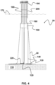
- Fig. 4 , Fig. 5 and Fig. 6 show various views of a particularly preferred collection station, which protects six systems connected to it via medium-voltage switchgear, combines the output of the wind turbines via an electrical busbar and is connected to the onshore power grid at the same voltage level via a transmission cable.
- the above-mentioned figures show a collection platform 20 on which six submarine cables 30 from six wind turbines are connected.
- An anchoring element 120 is provided in the seabed 110, which can be, for example, a pile or a suction cup. This element represents a firm anchor between the bottom 110 and the collection platform 20 and, if necessary, also for additional connection of the wind turbines 10 with the aid of mooring lines or chains 130.
- Several connecting elements 140 for example made of synthetic lines or wire ropes, are provided on this anchoring element 120.
- a buoyancy body 150 is attached to the upper end of these connecting elements 140, which generates so much buoyancy through its own displacement that the entire collection platform 20 is kept floating upright in the water without vertical movements and only a few horizontal and rotational movements. can be carried out.
- a plurality of supports 180 are attached to the floating body 150, which extend vertically upwards through the water surface 170 and to the upper end of which a platform 190 is attached, which accommodates the switchgear 210 for each individual wind turbine 10.
- the length of the supports 180 is advantageously selected so that a largest anticipated wave neither exposes the top of the buoyancy body 150 nor hits the platform 190 on its underside.
- the floating height of the floating platform 20 can then be adjusted so that the top of the floating body 150 and the underside of the platform 190 are approximately evenly spaced from the average water level of the water surface 170.
- Protective pipes 160 are attached to the support structure 180, which accommodate and protect the submarine cables 30 to the individual wind turbines 10.
- a boat landing 220 for maintenance purposes, access to the platform 190 is provided by a boat landing 220.
- a boat landing 220 On the platform 190, preferably in a circle, as many switchgear assemblies 210 are arranged as there are wind turbines 10 to be connected to a collecting platform 20 via the submarine cables 30.
- the entire platform 190, including the switchgear 210, is protected against the effects of the weather by a panel (not shown). Dehumidifiers and heaters are to be provided if necessary.
- the switchgear 210 is brought together on an electrical busbar 230 and connected to a grid feed-in point on land or an offshore collection station via the transmission line 220. There is no conversion of electrical energy on this collection platform 20, but rather only the energy of the individual wind turbines 10 is combined at the same voltage level and discharged via the collection cable 220. Fiber optic cables are also routed via this transmission line 220, which are used, for example, to control the switchgear 210.
Landscapes
- Engineering & Computer Science (AREA)
- Chemical & Material Sciences (AREA)
- Combustion & Propulsion (AREA)
- Mechanical Engineering (AREA)
- Power Engineering (AREA)
- Life Sciences & Earth Sciences (AREA)
- Sustainable Development (AREA)
- Sustainable Energy (AREA)
- General Engineering & Computer Science (AREA)
- Ocean & Marine Engineering (AREA)
- Wind Motors (AREA)
Description
- Die Erfindung betrifft einen Offshore-Windpark mit einer Mehrzahl von schwimmenden Single-Point-Mooring-Windenergieanlagen. Insbesondere betrifft die Erfindung einen Offshore-Windpark mit einer Mehrzahl von innerhalb von parkettiert angeordneten Teilflächen angeordneten schwimmenden Single-Point-Mooring-Windenergieanlagen und einer mit den schwimmenden Single-Point-Mooring-Windenergieanlagen verbundenen Sammelstation, die mittels einer Übertragungsleitung mit einem Stromnetz verbunden ist.
- Die Ausgestaltung von Windparks ist insbesondere aus der
WO 2012/048743 A1 , derCN 110 654 510 A , derDE 10 2015 121 371 A1 und derUS 2013/152839 A1 bekannt. - Insbesondere die
WO 2012/048743 offenbart einen Offshore-Windpark mit, um eine zentrale Station in gleichen Abstand sternförmig angeordneten und einzeln angebundenen, Windenergieanlagen. - Die Windenergieanlagen eines Offshore-Windparks mit fest am Boden verankerten Windenergieanlagen werden üblicherweise mittels einer in
Fig. 1 dargestellten Ringverkabelung gemäß einer Ringtopologie (Fig. 1a ) oder als Radialverkabelung gemäß einer Linientopologie (Fig. 1b ) an das Stromnetz angebunden. - Bei der in
Fig. 1a dargestellten Ringverkabelung werden mehrere Windenergieanlagen 10 eines Offshore-Windparks 100 zu einer Ringleitung 30 verschaltet, deren beiden Enden mit einer beispielsweise als Umspannplattform ausgebildeten Sammelstation 20 verbunden sind, die mittels einer (nicht dargestellten) zentralen Übertragungsleitung mit einem Stromnetz verbunden ist. Bei dieser Verkabelung wird die gesamte Leistung aller im Ringschluss angeordneten Windenergieanlagen 10 über das Kabel 30 übertragen. Zur Übertragung der Summe der elektrischen Ströme der Einzelanlagen ist die Verwendung eines sehr dicken Kabels erforderlich, wobei die Installation des Kabels aufgrund dessen Gewichts und Steifigkeit sehr aufwändig ist. Ein weiterer Nachteil der Ringtopologie besteht darin, dass drei Mittelspannungsschaltanlagen für jede einzelne Anlage erforderlich sind, um die verbleibenden Anlagen des Rings im Fall des Defekts oder der Wartung einer der Anlagen weiterbetreiben zu können. Diese Schaltanlagen benötigen Platz und sind aufwändig herzustellen, zu installieren und darüber hinaus auch störanfällig. - Eine andere Möglichkeit - wie in
Fig. 1b gezeigt - ist die Windenergieanlagen 10 des Offshore-Windparks gemäß der Linientopologie in Reihen zu verbinden und dann mittels eines Kabels 30 auf die Sammelstation 20 zu führen. Gegenüber der Ringverkabelung hat diese Anordnung den Nachteil, dass bei einem Ausfall einer Leitung zwischen den Anlagen die von der Sammelstation 20 aus gesehen hinter diesem Schaden angeordneten Anlagen 10 nicht mehr betrieben werden können und ausgeschaltet werden müssen. Zugleich sind bei dieser Anordnung für jede einzelne Windenergieanlage mehrere Schaltanlagen notwendig, sodass auch ein hoher Installationsaufwand besteht. - Wenngleich die insgesamt benötigte Kabellänge bei der Linientopologie geringer ausfällt als bei der Ringtopologie führt die Verwendung eines sehr leistungsstarken, dicken Kabels und die Anzahl der benötigten Schaltanlagen zu einem für die Anbindung der Offshore-Windenergieanlagen hohen Material- und Arbeitsaufwand.
- Insbesondere ist aber die Verwendung eines schweren Seekabels bei der Installation von schwimmenden Single-Point-Mooring-Windenergieanlagen hinderlich, da dieses aufgrund seines Eigengewichts und seiner Steifigkeit die Schwimmeigenschaften, insbesondere die Selbstausrichtung dieser schwimmenden Offshore-Windenergieanlagen behindert. Im Gegensatz zu bodengebundenen Offshore Anlagen wird durch die große vertikale und horizontale Bewegung des Schwimmfundaments derartiger Windenergieanlagen und durch Wind- und Wellenlasten eine starke mechanische Beanspruchung der Kabel verursacht, sodass die durch diese Bewegungen verursachten Bewegungen der Kabel hohe Ansprüche an die Haltbarkeit der Kabel stellen, die folglich eine Schwachstelle für den durchgängigen Betrieb sind.
- Aufgabe der Erfindung ist es daher insbesondere, eine elektrische Anbindung von schwimmenden Single-Point-Mooring-Windenergieanlagen an eine Sammelstation zu schaffen, die mit geringem Material- und Arbeitsaufwand, mit möglichst geringem Einfluss auf die Schwimmeigenschaften der Windenergieanlagen und mit größtmöglicher Bewegungsfreiheit der schwimmenden Windenergieanlage und dabei gegebener Langzeithaltbarkeit der Kabel ermöglicht werden kann.
- Diese Aufgabe wird erfindungsgemäß durch Offshore-Windpark mit den Merkmalen von Anspruch 1 gelöst. Die Unteransprüche geben vorteilhafte Ausgestaltungen der Erfindung wieder.
- Der Grundgedanke der Erfindung besteht darin, wenigstens eine Teilmenge einer Mehrzahl von einen Offshore-Windpark bildenden schwimmenden Single-Point-Mooring-Windenergieanlagen mittels einer Sternverkabelung an eine Sammelstation anzuschließen. Dabei überträgt jedes von einer Windenergieanlage zur Sammelstation führende Kabel nur die Leistung einer einzelnen Anlage und nicht etwa die Leistung mehrerer zu einem Strang zusammengefasster Anlagen, sodass die verwendeten Kabel entsprechend dünner und mit größerer Flexibilität ausgelegt werden können. Zusätzlich ist die Summe der Längen der sternförmig verlaufenden Verbindungen zwischen jeweils einer schwimmenden Single-Point-Mooring-Windenergieanlage und der Sammelstation geringer ist als die Länge einer gedachten die Sammelstation und die schwimmenden Single-Point-Mooring-Windenergieanlagen miteinander verbindenden Linie. Durch diese Maßnahme kann eine weitere Materialeinsparung erfolgen.
- Erfindungsgemäß wird ein Offshore-Windpark mit einer Mehrzahl von innerhalb von parkettiert angeordneten Teilflächen angeordneten schwimmenden Single-Point-Mooring-Windenergieanlagen und einer mit den schwimmenden Single-Point-Mooring-Windenergieanlagen verbundenen Sammelstation, die mittels einer Übertragungsleitung mit einem Stromnetz verbunden ist, vorgeschlagen, wobei wenigstens eine Teilmenge der Mehrzahl von schwimmenden Single-Point-Mooring-Windenergieanlagen unter Ausbildung eines sternförmigen Stromnetzes jeweils mit einem eigenen Seekabel direkt mit der Sammelstation verbunden ist, wobei die Summe der Länge der direkten Verbindungen zwischen den schwimmenden Single-Point-Mooring-Windenergieanlagen und der Sammelstation geringer ist als die Länge einer gedachten die Sammelstation und die schwimmenden Single-Point-Mooring-Windenergieanlagen miteinander verbindenden Linie.
- Die Ausbildung des erfindungsgemäßen Offshore-Windparks mit einer sternförmigen Topologie erfordert also insgesamt eine geringere Kabellänge als zur Ausbildung einer Ring- oder Linientopologie erforderlich wäre, bei der die Sammelstation und die schwimmenden Single-Point-Mooring-Windenergieanlagen linear miteinander verbunden sind.
- Nach einem bevorzugten Ausführungsbeispiel ist die elektrische Spannungsebene des in den zur Sammelstation führenden Seekabeln geführten Stroms mit der elektrischen Spannungsebene des in der mit der Übergabestation verbundenen Übertragungsleitung geführten Stroms identisch. Besonders bevorzugt ist vorgesehen, dass die elektrische Spannung des in den zur Sammelstation führenden Seekabeln geführten Stroms mit der elektrischen Spannung des in der mit der Übergabestation verbundenen Übertragungsleitung geführten Stroms identisch ist. Höchst bevorzugt beträgt die Spannung sowohl in den Seekabeln als auch in der Übertragungsleitung 66 kV.
- Die direkte Verbindung einer schwimmenden Single-Point-Mooring-Windenergieanlage zur Sammelstation ist dabei insbesondere derart ausgelegt, dass das entsprechend verwendete Seekabel so kurz und so dünn wie möglich ausgeführt ist. Insbesondere nimmt die Sammelstation auch die Schaltanlagen der mit der Sammelstation verbundenen Windenergieanlagen auf, ohne dass die Single-Point-Mooring-Windenergieanlagen selbst Schaltanlagen aufweisen und so eine einfache, kostengünstige und kompakte Installation ermöglicht ist. Bei dieser Verschaltung wird pro Anlage nur eine einzige Schaltanlage pro Single-Point-Mooring-Windenergieanlage benötigt und nicht drei Schaltanlagen wie im Fall der Ringverkabelung. Dabei stellt eine Teilfläche diejenige (gedachte) polygonale Fläche in Draufsicht auf den Offshore-Windpark dar, die jeweils einer schwimmenden Single-Point-Mooring-Windenergieanlage einschließlich deren Verankerung zugeordnet ist. Die parkettiert angeordneten Teilflächen können als Dreieck, Rechteck oder Hexagon ausgebildet sein, wobei die Eckpunkte der Teilfläche - wie bereits aus der
DE 10 2015 121 371 B4 bekannt - insbesondere die Positionen der Gründungen darstellen, mit deren Hilfe die schwimmenden Single-Point-Mooring-Windenergieanlagen am Gewässerboden fixiert sind. - Alternativ kann es sich dabei um gedachte Teilflächen handeln, deren Geometrie speziell durch einen vorbestimmten Abstand der Windenergieanlagen zueinander definiert ist. Dieser vorbestimmte Abstand kann beispielsweise ein Vielfaches des Rotordurchmessers der im Offshore-Windpark installierten Windenergieanlagen sein.
- Die Sammelstation ist dabei nicht außerhalb eines die schwimmenden Windenergieanlagen aufweisenden Felds, sondern insbesondere im Mittelpunkt eines wenigstens die Teilmenge der schwimmenden Single-Point-Mooring-Windenergieanlagen umfassenden Umkreises angeordnet. Speziell ist die mit den schwimmenden Single-Point-Mooring-Windenergieanlagen verbundene Sammelstation besonders bevorzugt im Schwerpunkt der Parkettierung der mit der Sammelstation verbundenen schwimmenden Single-Point-Mooring-Windenergieanlagen angeordnet. Diese bevorzugten Anordnungen ermöglichen jeweils eine vorteilhafte Ausgestaltung der Erfindung, die im Hinblick auf die Verkabelung besonders materialschonend ausgeführt werden kann.
- Eine besonders vorteilhafte Ausgestaltung hinsichtlich der Fertigung, Installation und Wartung des Offshore-Windparks wird auch dann erreicht, wenn die Sammelstation schwimmend ausgebildet ist. Die Sammelstation kann in diesem Fall nämlich an Land gefertigt, auf Ihre Funktion überprüft und zum Ort Ihrer Installation geschleppt werden, wobei auch ein einfacher Austausch möglich bleibt. Dabei kann die schwimmende Sammelstation insbesondere als Tension-Leg-Plattform (TLP) ausgebildet und höchst bevorzugt mit einer eine schwimmende Single-Point-Mooring-Windenergieanlage am Boden befestigenden Gründung verbunden sein. Derart wird der Material- und Installationsaufwand des Offshore-Windparks weiter verringert.
- Weiter ist bevorzugt vorgesehen, dass eine weitere Teilmenge der Mehrzahl von schwimmenden Single-Point-Mooring-Windenergieanlagen unter Ausbildung eines weiteren sternförmigen Stromnetzes jeweils mit einem eigenen Seekabel direkt mit einer weiteren Sammelstation verbunden ist. Mit anderen Worten kann der Offshore-Windpark in einzelne Gruppen (Cluster) unterteilt sein, wobei ein Cluster aus einer Sammelstation und den mit dieser verbundenen schwimmenden Single-Point-Mooring-Windenergieanlagen besteht.
- Als besonders vorteilhaft hat sich herausgestellt, wenn die Teilmenge oder die weitere Teilmenge der Mehrzahl von schwimmenden Single-Point-Mooring-Windenergieanlagen bevorzugt sechs schwimmende Single-Point-Mooring-Windenergieanlagen umfasst. Dieses ist insbesondere hinsichtlich des Installations- und Materialaufwands bei einer Parkettierung mit als Hexagonen ausgebildeten Teilflächen vorteilhaft.
- Schließlich ist die Sammelstation bevorzugt mittels einer zentralen Übertragungsleitung mit einem landseitigen Stromnetz oder mit einer weiteren größeren Sammel- bzw. Umspannplattform als Teil eines Stromnetzes verbunden. Insbesondere sind die schwimmenden Single-Point-Mooring-Windenergieanlagen zur Erzeugung von elektrischer Leistung auf Hochspannungsebene, z.B. 66 kV, eingerichtet, die in der Sammelstation mit Hilfe einer elektrischen Sammelschiene zusammengeschossen werden, wobei die Sammelstation ohne weitere Umspannung auf eine höhere Wechsel- oder Gleichspannungsebene mit dem landseitigen Stromnetz mittels der zentralen Übertragungsleitung verbunden ist.
- Die Erfindung wird im Folgenden anhand eines in den beigefügten Zeichnungen dargestellten, besonders bevorzugt ausgestalteten Ausführungsbeispiels näher erläutert. Es zeigen:
- Fig. 2
- eine bevorzugte Ausgestaltung eines Offshore-Windparks mit schwimmenden Single-Point-Mooring-Windenergieanlagen, die unter Ausbildung eines sternförmigen Stromnetzes jeweils mit einem eigenen Seekabel direkt mit einer Sammelstation des Offshore-Windparks verbunden sind;
- Fig. 3
- eine besonders bevorzugte Ausgestaltung eines Offshore-Windparks mit innerhalb von parkettiert angeordneten Teilflächen angeordneten schwimmenden Single-Point-Mooring-Windenergieanlagen;
- Fig. 4
- eine Seitenansicht einer besonders bevorzugt ausgestalteten Sammelstation;
- Fig. 5
- eine perspektivische Ansicht der in
Fig. 4 dargestellten Sammelstation; und - Fig. 6
- eine Detailansicht des oberen Bereichs der zuvor dargestellten Sammelstation.
-
Fig. 2 zeigt eine schematische Draufsicht einer bevorzugten Ausgestaltung innerhalb eines Offshore-Windparks gruppierter schwimmender Single-Point-Mooring-Windenergieanlagen, die unter Ausbildung eines sternförmigen Stromnetzes jeweils mit einem eigenen Seekabel direkt mit einer der Gruppierung zugeordneten Sammelstation 20 des Offshore-Windparks verbunden sind. - Insbesondere zeigt
Fig. 2 eine Ausgestaltung eines Offshore-Windparks 100 mit einer Mehrzahl von schwimmenden Single-Point-Mooring-Windenergieanlagen 10, jeweils einer Sammelstation 20 und einer Mehrzahl von jeweils eine schwimmende Single-Point-Mooring-Windenergieanlage 10 direkt mit der Sammelstation 20 verbindenden Seekabeln 30, sodass ein sternförmiges Verbindungsnetz geschaffen wird. - Die schwimmenden Single-Point-Mooring-Windenergieanlagen 10 sind innerhalb vorbestimmter Teilflächen 40 angeordnet, die parkettiert angeordnet sind und das Gesamtareal des Offshore-Windparks darstellen. Die Teilflächen 40 sind in
Fig. 2 als Hexagon ausgebildet. Entweder orientiert sich die Parkettierung dabei an den die jeweilige schwimmende Single-Point-Mooring-Windenergieanlage 10 verankernden Gründungselementen oder alternativ an einem anderen Faktor, insbesondere an einem Vielfachen des Rotordurchmessers der im Offshore-Windpark angeordneten schwimmenden Single-Point-Mooring-Windenergieanlagen 10. - Die Sammelstation 20 ist in
Fig. 2 im Mittelpunkt eines gestrichelt dargestellten, die schwimmenden Single-Point-Mooring-Windenergieanlagen 10 umfassenden Umkreises angeordnet. Dabei ist die Sammelstation 20 des inFig. 2 gezeigten Offshore-Windparks 100 im Schwerpunkt der Parkettierung der mit der Sammelstation 20 verbundenen schwimmenden Single-Point-Mooring-Windenergieanlagen 10 angeordnet. - Entsprechend der Erfindung ist die Summe der Länge der direkten Verbindungen zwischen den schwimmenden Single-Point-Mooring-Windenergieanlagen 10 und der Sammelstation 20 geringer als die Länge einer gedachten die Sammelstation 20 und die schwimmenden Single-Point-Mooring-Windenergieanlagen 10 miteinander verbindenden Linie, die zu Ausbildung einer Ring- oder Linientopologie erforderlich wäre.
- Die in
Fig. 2 dargestellte Ausgestaltung weist die kürzeste Gesamtlänge der erforderlichen Verbindungen zwischen den schwimmenden Single-Point-Mooring-Windenergieanlagen 10 und der Sammelstation 20 auf, wobei die Gesamtlänge der 5,19-fachen Länge des Abstandes zwischen den Einzelanlagen ausmacht und der Mittelwert der Kabellängen das 0,86-fache des Anlagenabstandes beträgt. Bei einer Ringverkabelung würde der Mittelwert der Kabellängen zwischen den Anlagen mindestens das 1,4-fache des Anlagenabstandes betragen und damit ein deutlich dickeres und somit auch teureres Kabel benötigt werden. - Die Sammelstation 20 ist - wie
Fig. 4 bis Fig. 6 zeigen - bevorzugt schwimmend, insbesondere als Tension-Leg-Plattform (TLP) ausgebildet und darüber hinaus mit einer eine benachbarte schwimmende Single-Point-Mooring-Windenergieanlage 10 am Boden befestigenden Gründung verbunden, sodass der Material- und Installationsaufwand des Offshore-Windparks 100 gegenüber herkömmlichen Offshore-Windparks reduziert ist. - Dem in
Fig. 2 dargestellten Ausführungsbeispiel kommt besondere Bedeutung zu, da sich die dargestellte Gruppierung aus sechs schwimmenden Single-Point-Mooring-Windenergieanlagen 10, die innerhalb aus parkettierten, jeweils als Hexagon ausgebildeten Teilflächen 40 angeordnet sind, für die Ausbildung größerer Offshore-Windparks eignet, bei dem - wieFig. 3 zeigt - weitere Teilmengen der den Offshore-Windpark 100 bildenden schwimmenden Single-Point-Mooring-Windenergieanlagen 10 unter Ausbildung jeweils weiterer sternförmiger Stromnetze jeweils mit einem eigenen Seekabel 30 direkt mit jeweils einer weiteren Sammelstation 20 verbunden sind. - Die mittlere Kabellänge der in jeweils aus sechs Anlagen bestehenden Gruppen beträgt jeweils nur 86 % des Abstandes der Anlagen zueinander. Zur Trennung der Anlagen vom Netz wird - im Gegensatz zu einer Ringverkabelung, bei der drei Schaltanlagen pro Anlage benötigt werden - nur jeweils eine Schaltanlage pro Anlage an der Sammelstation 20 benötigt, sodass auch beim Abschalten einer Anlage allein alle anderen Anlagen unbeeinflusst bleiben und Energie produzieren können.
- Die Ausbildung der Teilflächen 40 als Hexagone hat den Vorteil, dass zur Verankerung der schwimmenden Single-Point-Mooring-Windenergieanlagen 10 eine hinsichtlich der Verteilung der Zugkräfte vorteilhafte Ausführung mit sechs Mooringleinen in jeweils einem Winkel von 60° verwendet werden kann. Bei geschickter Anordnung von 6er-Gruppen werden die von den Anlagen 10 führenden Seekabel 30 jeweils zu einer Sammelstation 20 geführt, wobei dort die sechs Schaltanlagen für die sechs Anlagen untergebracht sind und die Verbindung auf einer elektrischen Sammelschiene zum Anschluss an die Übertragungsleitung hergestellt wird.
- Werden die Anlagen 10 bei einem Spannungslevel von 66 kV verschaltet wird ergibt sich für sechs Anlagen der zukünftigen Leistungsklasse von >15 MW eine Übertragungsleistung von 6 x 15 MW = 90+ MW. Dieses kann über eine einzige Übertragungsleitung an Land übertragen werden, sodass ein weiteres Offshore-Umspannwerk im Windpark nicht erforderlich ist.
-
Fig. 3 zeigt insbesondere einen Offshore-Windpark 100 mit insgesamt 102 schwimmenden Single-Point-Mooring-Windenergieanlagen 10 mit einer Gesamtleistung von >1.500 MW. Die Single-Point-Mooring-Windenergieanlagen 10 jeweils sind in 18 Gruppen zu 6 Anlagen 10 aufgeteilt. Die Gesamtleistung wird insbesondere mit 18 Einzelleitungen auf 66 kV Ebene an Land übertragen. Gegenüber einer Ringverkabelung mit 306 Schaltanlagen werden bei der hier dargestellten Ausgestaltung nur 102 Schaltanlagen benötigt. Bei einem aktuellen Stückpreis von ca. 100.000 € macht das einen Kostenunterschied von 20 Mio € aus. Die Kabellänge der Parkverkabelung ist in diesem bevorzugten Ausführungsbeispiele auf 88 Anlagenabstände (ca. 110 km Kabellänge) reduziert, wobei bei einer Ringverkabelung mindestens 144 Anlagenabständen (ca. 180 km Kabellänge) zu berücksichtigen wären. Unter Berücksichtigung der Verlege- und Kabelkosten macht dieses einen Unterschied von ca. 40 Mio € aus. Dabei ist aber noch zu bedenken, dass die Kabel zum Anschluss der Einzelanlagen an die Sammelstation wesentlich dünner und kostengünstiger ausfallen. Dieses Beispiel zeigt die Reduzierung des Material- und Installationsaufwand derartiger Offshore-Windparks sehr deutlich. -
Fig. 4 ,Fig. 5 undFig. 6 zeigen verschiedene Ansichten einer besonders bevorzugt ausgestalteten Sammelstation, die sechs mit dieser verbundene Anlagen über Mittelspannungsschaltanlagen absichert, über eine elektrische Sammelschiene die Leistung der Windenergieanlagen zusammenführt und auf derselben Spannungsebene über ein Übertragungskabel mit dem landseitigen Stromnetz verbunden ist. - Insbesondere zeigen die vorgenannten Abbildungen eine Sammelplattform 20, an der sechs Seekabel 30 von sechs Windenergieanlagen zusammengeschaltet werden. Im Meeresboden 110 ist ein Verankerungselement 120 vorgesehen, das beispielweise ein Rammpfahl oder auch eine Sauglocke sein kann. Dieses Element stellt eine feste Verankerung zwischen dem Boden 110 und der Sammelplattform 20 und gegebenenfalls auch zur zusätzlichen Anbindung der Windenergieanlagen 10 mit Hilfe von Mooringleinen oder -ketten 130 dar. An diesem Verankerungselement 120 sind mehrere Verbindungselemente 140, beispielsweise aus Synthetikleinen oder Drahtseilen, vorgesehen. Am oberen Ende dieser Verbindungselemente 140 ist ein Auftriebskörper 150 befestigt, der durch seien eigene Verdrängung so viel Auftrieb erzeugt, dass die gesamte Sammelplattform 20 aufrecht schwimmend im Wasser gehalten wird, ohne dass vertikale Bewegungen und nur wenig horizontale- und Rotationsbewegungen ausgeführt werden können. Durch eine geschickte Anordnung der Verbindungelemente 140 können die Bewegungen minimiert werden, auch bei starkem Wellengang. Auf dem Schwimmkörper 150 ist eine Mehrzahl von Trägern 180 befestigt, die senkrecht nach oben durch die Wasseroberfläche 170 stoßen und an deren oberen Ende eine Plattform 190 befestigt ist, die die Schaltanlagen 210 für jede einzelne Windkraftanlage 10 aufnimmt. Die Länge der Träger 180 ist dabei vorteilhaft so zu wählen, dass eine größte anzunehmende Welle weder die Oberseite des Auftriebskörpers 150 freilegt, noch die Plattform 190 an deren Unterseite trifft. Durch die Einstellung der Länge der Verbindungselemente 140 ist dann die der Schwimmplattform 20 in der Schwimmhöhe so einzustellen, dass die Oberseite des Schwimmkörpers 150 und die Unterseite der Plattform 190 zirka gleichmäßig vom mittleren Wasserstand der Wasseroberfläche 170 entfernt sind. An der Trägerstruktur 180 sind Schutzrohre 160 befestigt, die die Seekabel 30 zu den einzelnen Windenergieanlagen 10 aufnehmen und schützen.
- Zusätzlich ist für Wartungszwecke, die Zugänglichkeit zur Plattform 190 durch ein Bootanlandung 220 geschaffen. Auf der Plattform 190 sind bevorzugt kreisförmig so viele Schaltanlagen 210 angeordnet wie Windenergieanlagen 10 über die Seekabel 30 an eine Sammelplattform 20 angeschlossen werden sollen. Die gesamte Plattform 190 inklusive der Schaltanlagen 210 ist durch eine nicht gezeichnete Verkleidung gegen Witterungseinflüsse geschützt. Gegebenenfalls sind Entfeuchter und Heizungen vorzusehen.
- Die Schaltanlagen 210 werden auf einer elektrischen Sammelschiene 230 zusammengeführt und über die Übertragungsleitung 220 mit einem Netzeinspeisepunkt an Land oder einer Offshore-Sammelstation verbunden. Auf diese Sammelplattform 20 findet kein Umspannen der elektrischen Energie satt, sondern nur die Zusammenfassung der Energie der einzelnen Windenergieanlagen 10 auf dem gleichen Spannungsniveau und Ableitung über das Sammelkabel 220. Über diese Übertragungsleitung 220 werden auch Glasfaserleitungen geführt, die z.B. zur Ansteuerung der Schaltanlagen 210 dienen.
Claims (12)
- Offshore-Windpark (100) mit einer Mehrzahl von innerhalb von parkettiert angeordneten Teilflächen (40) angeordneten schwimmenden Single-Point-Mooring-Windenergieanlagen (10) und einer mit den schwimmenden Single-Point-Mooring-Windenergieanlagen (10) verbundenen Sammelstation (20), die mittels einer Übertragungsleitung (220)-mit einem Stromnetz verbunden ist,
dadurch gekennzeichnet, dass
wenigstens eine Teilmenge der schwimmenden Single-Point-Mooring-Windenergieanlagen (10) unter Ausbildung eines sternförmigen Stromnetzes jeweils mit einem eigenen Seekabel (30) direkt mit der Sammelstation (20) verbunden ist, wobei die Summe der Länge der direkten Verbindungen zwischen den schwimmenden Single-Point-Mooring-Windenergieanlagen (10) und der Sammelstation (20) geringer ist als die Länge einer gedachten die Sammelstation (20) und die schwimmenden Single-Point-Mooring-Windenergieanlagen (10) miteinander verbindenden Linie. - Offshore-Windpark (100) nach Anspruch 1, dadurch gekennzeichnet, dass die elektrische Spannungsebene des in den zur Sammelstation (20) führenden Seekabeln (30) geführten Stroms mit der elektrischen Spannungsebene des in der mit der Übergabestation verbundenen Übertragungsleitung (220) geführten Stroms identisch ist.
- Offshore-Windpark (100) nach einem der vorhergehenden Ansprüche, dadurch gekennzeichnet, dass die elektrische Spannung des in den zur Sammelstation (20) führenden Seekabeln (30) geführten Stroms mit der elektrischen Spannung des in der mit der Übergabestation verbundenen Übertragungsleitung (220) geführten Stroms identisch ist.
- Offshore-Windpark (100) nach einem der vorhergehenden Ansprüche, dadurch gekennzeichnet, dass die Sammelstation (20) im Mittelpunkt eines wenigstens die Teilmenge der schwimmenden Single-Point-Mooring-Windenergieanlagen (10) umfassenden Umkreises angeordnet ist.
- Offshore-Windpark (100) nach einem der vorhergehenden Ansprüche, dadurch gekennzeichnet, dass die Sammelstation (20) im Schwerpunkt der Parkettierung der mit der Sammelstation (20) verbundenen schwimmenden Single-Point-Mooring-Windenergieanlagen (10) angeordnet ist.
- Offshore-Windpark (100) nach einem der vorhergehenden Ansprüche, dadurch gekennzeichnet, dass die Sammelstation (20) schwimmend ausgebildet ist.
- Offshore-Windpark (100) nach Anspruch 6, dadurch gekennzeichnet, dass die Sammelstation (20) als Tension-Leg-Plattform (TLP) ausgebildet ist.
- Offshore-Windpark (100) nach einem der Ansprüche 6 und 7, dadurch gekennzeichnet, dass die Sammelstation (20) mit einer eine schwimmende Single-Point-Mooring-Windenergieanlage (10) am Boden befestigenden Gründung verbunden ist.
- Offshore-Windpark (100) nach einem der vorhergehenden Ansprüche, dadurch gekennzeichnet, dass eine weitere Teilmenge der schwimmenden Single-Point-Mooring-Windenergieanlagen (10) unter Ausbildung eines weiteren sternförmigen Stromnetzes jeweils mit einem eigenen Seekabel (30) direkt mit einer weiteren Sammelstation (20) verbunden ist.
- Offshore-Windpark (100) nach einem der vorhergehenden Ansprüche, dadurch gekennzeichnet, dass die Teilmenge oder die weitere Teilmenge sechs schwimmende Single-Point-Mooring-Windenergieanlagen (10) umfasst.
- Offshore-Windpark (100) nach einem der vorhergehenden Ansprüche, dadurch gekennzeichnet, dass das mit der Sammelstation (20) verbundene Stromnetz ein landseitiges Stromnetz ist.
- Offshore-Windpark (100) nach einem der vorhergehenden Ansprüche, dadurch gekennzeichnet, dass die Teilflächen der Parkettierung als Dreieck, Rechteck oder Hexagon ausgebildet sind.
Applications Claiming Priority (1)
| Application Number | Priority Date | Filing Date | Title |
|---|---|---|---|
| DE102021118328.6A DE102021118328A1 (de) | 2021-07-15 | 2021-07-15 | Offshore-Windpark mit einer Mehrzahl von schwimmenden Single-Point-Mooring-Windenergieanlagen |
Publications (3)
| Publication Number | Publication Date |
|---|---|
| EP4120502A1 EP4120502A1 (de) | 2023-01-18 |
| EP4120502B1 true EP4120502B1 (de) | 2024-12-11 |
| EP4120502C0 EP4120502C0 (de) | 2024-12-11 |
Family
ID=81749064
Family Applications (1)
| Application Number | Title | Priority Date | Filing Date |
|---|---|---|---|
| EP22174386.7A Active EP4120502B1 (de) | 2021-07-15 | 2022-05-19 | Offshore-windpark mit einer mehrzahl von schwimmenden single-point-mooring-windenergieanlagen |
Country Status (3)
| Country | Link |
|---|---|
| EP (1) | EP4120502B1 (de) |
| DE (1) | DE102021118328A1 (de) |
| ES (1) | ES3010707T3 (de) |
Family Cites Families (4)
| Publication number | Priority date | Publication date | Assignee | Title |
|---|---|---|---|---|
| WO2012048743A1 (de) | 2010-10-13 | 2012-04-19 | Abb Schweiz Ag | Stromübertragungsvorrichtung für eine windkraftanlage |
| EP2604501B1 (de) * | 2011-12-15 | 2015-02-18 | Andreas Graf | System und Verankerung und Anlagen von schwimmenden Windturbinentürmen und entsprechende Verfahren zum Anlegen und Ausstellen davon |
| DE102015121371B4 (de) | 2015-12-08 | 2018-11-15 | Aerodyn Consulting Singapore Pte Ltd | Offshore-Windpark |
| CN110654510A (zh) * | 2019-10-30 | 2020-01-07 | 惠生(南通)重工有限公司 | 一种共享系泊的海上风电平台群 |
-
2021
- 2021-07-15 DE DE102021118328.6A patent/DE102021118328A1/de not_active Withdrawn
-
2022
- 2022-05-19 ES ES22174386T patent/ES3010707T3/es active Active
- 2022-05-19 EP EP22174386.7A patent/EP4120502B1/de active Active
Also Published As
| Publication number | Publication date |
|---|---|
| DE102021118328A1 (de) | 2023-01-19 |
| EP4120502C0 (de) | 2024-12-11 |
| EP4120502A1 (de) | 2023-01-18 |
| ES3010707T3 (en) | 2025-04-04 |
Similar Documents
| Publication | Publication Date | Title |
|---|---|---|
| EP2299499B1 (de) | Schwimmende Photovoltaik-Anordnung | |
| EP1993901B1 (de) | Verankern von anordnungen von bojenartigen weks | |
| DE60221802T2 (de) | Schwimmende offshore-windkraftanlage | |
| DE60034647T2 (de) | Windkraftanlage | |
| EP1240426B1 (de) | Offshore-windenergieanlage mit subsysteme aufnehmenden austauschbaren containern | |
| EP3325801B1 (de) | Offshore-windpark | |
| DE10205988A1 (de) | Windenergieanlage | |
| EP4013961B1 (de) | Schwimmende windenergieanlage mit integriertem umspannwerk | |
| DE102009031256B4 (de) | Schwimmfähige Plattform zur Anordnung von Solarmodulen auf einem Gewässer | |
| DE4106976A1 (de) | Windkraftanlagen | |
| WO2020002160A1 (de) | Schwimmtragwerk für eine windkraftanlage | |
| DE212022000372U1 (de) | Modular zusammengesetzte Photovoltaikplattformstruktur, die starkem Wind und kräftigen Wellen standhalten kann | |
| EP3530809B1 (de) | Verbindungsstruktur für eine meeresinstallation | |
| WO2021018583A1 (de) | Tragstruktur, insbesondere für on- und/oder offshore-windenergieanlagen | |
| DE212023000121U1 (de) | Verankerungssystem für schwimmende Plattformen und Offshore-Windkraftsystem | |
| EP4120502B1 (de) | Offshore-windpark mit einer mehrzahl von schwimmenden single-point-mooring-windenergieanlagen | |
| DE102017119635B3 (de) | Elektrische Kupplung zur Anbindung einer Windenergieanlage an ein Stromnetz | |
| DE102009048984A1 (de) | Vorrichtung einer Unterkonstruktion für Windenergie-Turmanlagen | |
| DE10250482A1 (de) | Segment-Windschraube | |
| DE202011001695U1 (de) | Stahlturm für Windkraftanlagen | |
| EP0334241A1 (de) | Vorrichtung zur Nutzbarmachung von Windenergie | |
| EP2725223A2 (de) | Windkraftanlagengruppe | |
| DE102019130374A1 (de) | Photovoltaikinstallation an einem Turm | |
| EP4392670A1 (de) | Windenergieanlage und windpark | |
| DE102015121794B3 (de) | Ankervorrichtung und Schwimmvorrichtung |
Legal Events
| Date | Code | Title | Description |
|---|---|---|---|
| PUAI | Public reference made under article 153(3) epc to a published international application that has entered the european phase |
Free format text: ORIGINAL CODE: 0009012 |
|
| STAA | Information on the status of an ep patent application or granted ep patent |
Free format text: STATUS: THE APPLICATION HAS BEEN PUBLISHED |
|
| AK | Designated contracting states |
Kind code of ref document: A1 Designated state(s): AL AT BE BG CH CY CZ DE DK EE ES FI FR GB GR HR HU IE IS IT LI LT LU LV MC MK MT NL NO PL PT RO RS SE SI SK SM TR |
|
| STAA | Information on the status of an ep patent application or granted ep patent |
Free format text: STATUS: REQUEST FOR EXAMINATION WAS MADE |
|
| 17P | Request for examination filed |
Effective date: 20230515 |
|
| RBV | Designated contracting states (corrected) |
Designated state(s): AL AT BE BG CH CY CZ DE DK EE ES FI FR GB GR HR HU IE IS IT LI LT LU LV MC MK MT NL NO PL PT RO RS SE SI SK SM TR |
|
| GRAP | Despatch of communication of intention to grant a patent |
Free format text: ORIGINAL CODE: EPIDOSNIGR1 |
|
| STAA | Information on the status of an ep patent application or granted ep patent |
Free format text: STATUS: GRANT OF PATENT IS INTENDED |
|
| GRAS | Grant fee paid |
Free format text: ORIGINAL CODE: EPIDOSNIGR3 |
|
| RIC1 | Information provided on ipc code assigned before grant |
Ipc: B63B 35/44 20060101ALN20241002BHEP Ipc: F03D 9/25 20160101ALI20241002BHEP Ipc: B63B 21/50 20060101ALI20241002BHEP Ipc: F03D 13/25 20160101ALI20241002BHEP Ipc: H02J 3/38 20060101AFI20241002BHEP |
|
| GRAA | (expected) grant |
Free format text: ORIGINAL CODE: 0009210 |
|
| STAA | Information on the status of an ep patent application or granted ep patent |
Free format text: STATUS: THE PATENT HAS BEEN GRANTED |
|
| INTG | Intention to grant announced |
Effective date: 20241023 |
|
| AK | Designated contracting states |
Kind code of ref document: B1 Designated state(s): AL AT BE BG CH CY CZ DE DK EE ES FI FR GB GR HR HU IE IS IT LI LT LU LV MC MK MT NL NO PL PT RO RS SE SI SK SM TR |
|
| REG | Reference to a national code |
Ref country code: GB Ref legal event code: FG4D Free format text: NOT ENGLISH |
|
| REG | Reference to a national code |
Ref country code: CH Ref legal event code: EP |
|
| REG | Reference to a national code |
Ref country code: DE Ref legal event code: R096 Ref document number: 502022002351 Country of ref document: DE |
|
| REG | Reference to a national code |
Ref country code: IE Ref legal event code: FG4D Free format text: LANGUAGE OF EP DOCUMENT: GERMAN |
|
| U01 | Request for unitary effect filed |
Effective date: 20241216 |
|
| U07 | Unitary effect registered |
Designated state(s): AT BE BG DE DK EE FI FR IT LT LU LV MT NL PT RO SE SI Effective date: 20250110 |
|
| REG | Reference to a national code |
Ref country code: ES Ref legal event code: FG2A Ref document number: 3010707 Country of ref document: ES Kind code of ref document: T3 Effective date: 20250404 |
|
| U20 | Renewal fee for the european patent with unitary effect paid |
Year of fee payment: 4 Effective date: 20250303 |
|
| PG25 | Lapsed in a contracting state [announced via postgrant information from national office to epo] |
Ref country code: HR Free format text: LAPSE BECAUSE OF FAILURE TO SUBMIT A TRANSLATION OF THE DESCRIPTION OR TO PAY THE FEE WITHIN THE PRESCRIBED TIME-LIMIT Effective date: 20241211 |
|
| PG25 | Lapsed in a contracting state [announced via postgrant information from national office to epo] |
Ref country code: GR Free format text: LAPSE BECAUSE OF FAILURE TO SUBMIT A TRANSLATION OF THE DESCRIPTION OR TO PAY THE FEE WITHIN THE PRESCRIBED TIME-LIMIT Effective date: 20250312 |
|
| PG25 | Lapsed in a contracting state [announced via postgrant information from national office to epo] |
Ref country code: RS Free format text: LAPSE BECAUSE OF FAILURE TO SUBMIT A TRANSLATION OF THE DESCRIPTION OR TO PAY THE FEE WITHIN THE PRESCRIBED TIME-LIMIT Effective date: 20250311 |
|
| PG25 | Lapsed in a contracting state [announced via postgrant information from national office to epo] |
Ref country code: SM Free format text: LAPSE BECAUSE OF FAILURE TO SUBMIT A TRANSLATION OF THE DESCRIPTION OR TO PAY THE FEE WITHIN THE PRESCRIBED TIME-LIMIT Effective date: 20241211 |
|
| PG25 | Lapsed in a contracting state [announced via postgrant information from national office to epo] |
Ref country code: PL Free format text: LAPSE BECAUSE OF FAILURE TO SUBMIT A TRANSLATION OF THE DESCRIPTION OR TO PAY THE FEE WITHIN THE PRESCRIBED TIME-LIMIT Effective date: 20241211 |
|
| PG25 | Lapsed in a contracting state [announced via postgrant information from national office to epo] |
Ref country code: IS Free format text: LAPSE BECAUSE OF FAILURE TO SUBMIT A TRANSLATION OF THE DESCRIPTION OR TO PAY THE FEE WITHIN THE PRESCRIBED TIME-LIMIT Effective date: 20250411 |
|
| PGFP | Annual fee paid to national office [announced via postgrant information from national office to epo] |
Ref country code: NO Payment date: 20250523 Year of fee payment: 4 |
|
| PG25 | Lapsed in a contracting state [announced via postgrant information from national office to epo] |
Ref country code: SK Free format text: LAPSE BECAUSE OF FAILURE TO SUBMIT A TRANSLATION OF THE DESCRIPTION OR TO PAY THE FEE WITHIN THE PRESCRIBED TIME-LIMIT Effective date: 20241211 |
|
| PG25 | Lapsed in a contracting state [announced via postgrant information from national office to epo] |
Ref country code: CZ Free format text: LAPSE BECAUSE OF FAILURE TO SUBMIT A TRANSLATION OF THE DESCRIPTION OR TO PAY THE FEE WITHIN THE PRESCRIBED TIME-LIMIT Effective date: 20241211 |
|
| PGFP | Annual fee paid to national office [announced via postgrant information from national office to epo] |
Ref country code: IE Payment date: 20250521 Year of fee payment: 4 |
|
| PGFP | Annual fee paid to national office [announced via postgrant information from national office to epo] |
Ref country code: ES Payment date: 20250630 Year of fee payment: 4 |
|
| PLBE | No opposition filed within time limit |
Free format text: ORIGINAL CODE: 0009261 |
|
| STAA | Information on the status of an ep patent application or granted ep patent |
Free format text: STATUS: NO OPPOSITION FILED WITHIN TIME LIMIT |
|
| REG | Reference to a national code |
Ref country code: CH Ref legal event code: L10 Free format text: ST27 STATUS EVENT CODE: U-0-0-L10-L00 (AS PROVIDED BY THE NATIONAL OFFICE) Effective date: 20251022 |
|
| 26N | No opposition filed |
Effective date: 20250912 |
|
| REG | Reference to a national code |
Ref country code: CH Ref legal event code: H13 Free format text: ST27 STATUS EVENT CODE: U-0-0-H10-H13 (AS PROVIDED BY THE NATIONAL OFFICE) Effective date: 20251223 |
|
| PG25 | Lapsed in a contracting state [announced via postgrant information from national office to epo] |
Ref country code: CH Free format text: LAPSE BECAUSE OF NON-PAYMENT OF DUE FEES Effective date: 20250531 |
|
| PG25 | Lapsed in a contracting state [announced via postgrant information from national office to epo] |
Ref country code: MC Free format text: LAPSE BECAUSE OF FAILURE TO SUBMIT A TRANSLATION OF THE DESCRIPTION OR TO PAY THE FEE WITHIN THE PRESCRIBED TIME-LIMIT Effective date: 20241211 |
|
| U20 | Renewal fee for the european patent with unitary effect paid |
Year of fee payment: 5 Effective date: 20260313 |