EP4120447A1 - Hermetically sealed battery - Google Patents
Hermetically sealed battery Download PDFInfo
- Publication number
- EP4120447A1 EP4120447A1 EP21767741.8A EP21767741A EP4120447A1 EP 4120447 A1 EP4120447 A1 EP 4120447A1 EP 21767741 A EP21767741 A EP 21767741A EP 4120447 A1 EP4120447 A1 EP 4120447A1
- Authority
- EP
- European Patent Office
- Prior art keywords
- thin portion
- thin
- valve portion
- battery
- positive electrode
- Prior art date
- Legal status (The legal status is an assumption and is not a legal conclusion. Google has not performed a legal analysis and makes no representation as to the accuracy of the status listed.)
- Pending
Links
- 238000007789 sealing Methods 0.000 claims abstract description 62
- 229910052751 metal Inorganic materials 0.000 claims description 18
- 239000002184 metal Substances 0.000 claims description 18
- 238000010276 construction Methods 0.000 abstract 1
- 238000003466 welding Methods 0.000 description 54
- 230000005856 abnormality Effects 0.000 description 9
- 239000000203 mixture Substances 0.000 description 8
- 239000010410 layer Substances 0.000 description 6
- 229910052744 lithium Inorganic materials 0.000 description 6
- OKTJSMMVPCPJKN-UHFFFAOYSA-N Carbon Chemical compound [C] OKTJSMMVPCPJKN-UHFFFAOYSA-N 0.000 description 5
- 239000011248 coating agent Substances 0.000 description 5
- 238000000576 coating method Methods 0.000 description 5
- 239000003792 electrolyte Substances 0.000 description 5
- 239000007789 gas Substances 0.000 description 5
- 239000011255 nonaqueous electrolyte Substances 0.000 description 5
- 229910052782 aluminium Inorganic materials 0.000 description 4
- 239000003125 aqueous solvent Substances 0.000 description 4
- 239000011230 binding agent Substances 0.000 description 4
- -1 lithium transition metal Chemical class 0.000 description 4
- 239000007773 negative electrode material Substances 0.000 description 4
- 229910052759 nickel Inorganic materials 0.000 description 4
- 230000000712 assembly Effects 0.000 description 3
- 238000000429 assembly Methods 0.000 description 3
- 229910002804 graphite Inorganic materials 0.000 description 3
- 239000010439 graphite Substances 0.000 description 3
- 229910052748 manganese Inorganic materials 0.000 description 3
- 239000007774 positive electrode material Substances 0.000 description 3
- 229910052723 transition metal Inorganic materials 0.000 description 3
- 229910000838 Al alloy Inorganic materials 0.000 description 2
- WHXSMMKQMYFTQS-UHFFFAOYSA-N Lithium Chemical compound [Li] WHXSMMKQMYFTQS-UHFFFAOYSA-N 0.000 description 2
- 239000002033 PVDF binder Substances 0.000 description 2
- XAGFODPZIPBFFR-UHFFFAOYSA-N aluminium Chemical compound [Al] XAGFODPZIPBFFR-UHFFFAOYSA-N 0.000 description 2
- 229910021383 artificial graphite Inorganic materials 0.000 description 2
- 239000002388 carbon-based active material Substances 0.000 description 2
- 239000002131 composite material Substances 0.000 description 2
- 239000006258 conductive agent Substances 0.000 description 2
- 229910052802 copper Inorganic materials 0.000 description 2
- 239000010949 copper Substances 0.000 description 2
- 238000001035 drying Methods 0.000 description 2
- 239000011888 foil Substances 0.000 description 2
- 229920002981 polyvinylidene fluoride Polymers 0.000 description 2
- 150000003839 salts Chemical class 0.000 description 2
- 239000002002 slurry Substances 0.000 description 2
- 239000002344 surface layer Substances 0.000 description 2
- 229910052718 tin Inorganic materials 0.000 description 2
- RYGMFSIKBFXOCR-UHFFFAOYSA-N Copper Chemical compound [Cu] RYGMFSIKBFXOCR-UHFFFAOYSA-N 0.000 description 1
- 229910000881 Cu alloy Inorganic materials 0.000 description 1
- PXGOKWXKJXAPGV-UHFFFAOYSA-N Fluorine Chemical compound FF PXGOKWXKJXAPGV-UHFFFAOYSA-N 0.000 description 1
- UFHFLCQGNIYNRP-UHFFFAOYSA-N Hydrogen Chemical compound [H][H] UFHFLCQGNIYNRP-UHFFFAOYSA-N 0.000 description 1
- 229910001290 LiPF6 Inorganic materials 0.000 description 1
- HBBGRARXTFLTSG-UHFFFAOYSA-N Lithium ion Chemical compound [Li+] HBBGRARXTFLTSG-UHFFFAOYSA-N 0.000 description 1
- 239000006230 acetylene black Substances 0.000 description 1
- 229910045601 alloy Inorganic materials 0.000 description 1
- 239000000956 alloy Substances 0.000 description 1
- 150000001408 amides Chemical class 0.000 description 1
- 229910052796 boron Inorganic materials 0.000 description 1
- 229910052799 carbon Inorganic materials 0.000 description 1
- 229910052804 chromium Inorganic materials 0.000 description 1
- 150000001875 compounds Chemical class 0.000 description 1
- 150000004696 coordination complex Chemical class 0.000 description 1
- 230000007423 decrease Effects 0.000 description 1
- 230000000694 effects Effects 0.000 description 1
- 150000002148 esters Chemical class 0.000 description 1
- 150000002170 ethers Chemical class 0.000 description 1
- 229910052731 fluorine Inorganic materials 0.000 description 1
- 239000011737 fluorine Substances 0.000 description 1
- 229910052736 halogen Inorganic materials 0.000 description 1
- 125000005843 halogen group Chemical group 0.000 description 1
- 150000002367 halogens Chemical group 0.000 description 1
- 229910052739 hydrogen Inorganic materials 0.000 description 1
- 239000001257 hydrogen Substances 0.000 description 1
- 230000001771 impaired effect Effects 0.000 description 1
- 229910052738 indium Inorganic materials 0.000 description 1
- 229910052742 iron Inorganic materials 0.000 description 1
- 238000005304 joining Methods 0.000 description 1
- 239000011244 liquid electrolyte Substances 0.000 description 1
- 229910001416 lithium ion Inorganic materials 0.000 description 1
- 229910003002 lithium salt Inorganic materials 0.000 description 1
- 159000000002 lithium salts Chemical class 0.000 description 1
- 229910052749 magnesium Inorganic materials 0.000 description 1
- 238000004519 manufacturing process Methods 0.000 description 1
- 239000011325 microbead Substances 0.000 description 1
- 239000012046 mixed solvent Substances 0.000 description 1
- 229910021382 natural graphite Inorganic materials 0.000 description 1
- 229910052758 niobium Inorganic materials 0.000 description 1
- 150000002825 nitriles Chemical class 0.000 description 1
- 238000001556 precipitation Methods 0.000 description 1
- 238000003825 pressing Methods 0.000 description 1
- 239000011347 resin Substances 0.000 description 1
- 229920005989 resin Polymers 0.000 description 1
- 239000007784 solid electrolyte Substances 0.000 description 1
- 239000002904 solvent Substances 0.000 description 1
- 238000009987 spinning Methods 0.000 description 1
- 229920003048 styrene butadiene rubber Polymers 0.000 description 1
- 238000006467 substitution reaction Methods 0.000 description 1
- 229910052715 tantalum Inorganic materials 0.000 description 1
- 229910052719 titanium Inorganic materials 0.000 description 1
- 229910052721 tungsten Inorganic materials 0.000 description 1
- 229910052720 vanadium Inorganic materials 0.000 description 1
- 229910052725 zinc Inorganic materials 0.000 description 1
- 229910052726 zirconium Inorganic materials 0.000 description 1
Images


Classifications
-
- H—ELECTRICITY
- H01—ELECTRIC ELEMENTS
- H01M—PROCESSES OR MEANS, e.g. BATTERIES, FOR THE DIRECT CONVERSION OF CHEMICAL ENERGY INTO ELECTRICAL ENERGY
- H01M50/00—Constructional details or processes of manufacture of the non-active parts of electrochemical cells other than fuel cells, e.g. hybrid cells
- H01M50/30—Arrangements for facilitating escape of gases
- H01M50/342—Non-re-sealable arrangements
- H01M50/3425—Non-re-sealable arrangements in the form of rupturable membranes or weakened parts, e.g. pierced with the aid of a sharp member
-
- H—ELECTRICITY
- H01—ELECTRIC ELEMENTS
- H01M—PROCESSES OR MEANS, e.g. BATTERIES, FOR THE DIRECT CONVERSION OF CHEMICAL ENERGY INTO ELECTRICAL ENERGY
- H01M50/00—Constructional details or processes of manufacture of the non-active parts of electrochemical cells other than fuel cells, e.g. hybrid cells
- H01M50/10—Primary casings; Jackets or wrappings
- H01M50/102—Primary casings; Jackets or wrappings characterised by their shape or physical structure
- H01M50/107—Primary casings; Jackets or wrappings characterised by their shape or physical structure having curved cross-section, e.g. round or elliptic
-
- H—ELECTRICITY
- H01—ELECTRIC ELEMENTS
- H01M—PROCESSES OR MEANS, e.g. BATTERIES, FOR THE DIRECT CONVERSION OF CHEMICAL ENERGY INTO ELECTRICAL ENERGY
- H01M50/00—Constructional details or processes of manufacture of the non-active parts of electrochemical cells other than fuel cells, e.g. hybrid cells
- H01M50/10—Primary casings; Jackets or wrappings
- H01M50/147—Lids or covers
- H01M50/148—Lids or covers characterised by their shape
- H01M50/152—Lids or covers characterised by their shape for cells having curved cross-section, e.g. round or elliptic
-
- H—ELECTRICITY
- H01—ELECTRIC ELEMENTS
- H01M—PROCESSES OR MEANS, e.g. BATTERIES, FOR THE DIRECT CONVERSION OF CHEMICAL ENERGY INTO ELECTRICAL ENERGY
- H01M50/00—Constructional details or processes of manufacture of the non-active parts of electrochemical cells other than fuel cells, e.g. hybrid cells
- H01M50/50—Current conducting connections for cells or batteries
- H01M50/531—Electrode connections inside a battery casing
- H01M50/534—Electrode connections inside a battery casing characterised by the material of the leads or tabs
-
- H—ELECTRICITY
- H01—ELECTRIC ELEMENTS
- H01M—PROCESSES OR MEANS, e.g. BATTERIES, FOR THE DIRECT CONVERSION OF CHEMICAL ENERGY INTO ELECTRICAL ENERGY
- H01M50/00—Constructional details or processes of manufacture of the non-active parts of electrochemical cells other than fuel cells, e.g. hybrid cells
- H01M50/50—Current conducting connections for cells or batteries
- H01M50/572—Means for preventing undesired use or discharge
- H01M50/574—Devices or arrangements for the interruption of current
- H01M50/578—Devices or arrangements for the interruption of current in response to pressure
-
- H—ELECTRICITY
- H01—ELECTRIC ELEMENTS
- H01M—PROCESSES OR MEANS, e.g. BATTERIES, FOR THE DIRECT CONVERSION OF CHEMICAL ENERGY INTO ELECTRICAL ENERGY
- H01M2200/00—Safety devices for primary or secondary batteries
- H01M2200/20—Pressure-sensitive devices
-
- Y—GENERAL TAGGING OF NEW TECHNOLOGICAL DEVELOPMENTS; GENERAL TAGGING OF CROSS-SECTIONAL TECHNOLOGIES SPANNING OVER SEVERAL SECTIONS OF THE IPC; TECHNICAL SUBJECTS COVERED BY FORMER USPC CROSS-REFERENCE ART COLLECTIONS [XRACs] AND DIGESTS
- Y02—TECHNOLOGIES OR APPLICATIONS FOR MITIGATION OR ADAPTATION AGAINST CLIMATE CHANGE
- Y02E—REDUCTION OF GREENHOUSE GAS [GHG] EMISSIONS, RELATED TO ENERGY GENERATION, TRANSMISSION OR DISTRIBUTION
- Y02E60/00—Enabling technologies; Technologies with a potential or indirect contribution to GHG emissions mitigation
- Y02E60/10—Energy storage using batteries
Definitions
- a lithium transition metal complex oxide is used as the positive electrode active material.
- the metal element contained in the lithium transition metal complex oxide include Ni, Co, Mn, Al, B, Mg, Ti, V, Cr, Fe, Cu, Zn, Ga, Sr, Zr, Nb, In, Sn, Ta, W, and the like.
- An example of a suitable lithium transition metal complex oxide is a lithium metal complex oxide containing at least one of Ni, Co, and Mn. Specific examples include composite oxides containing Ni, Co, and Mn and composite oxides containing Ni, Co, and Al.
- the positive electrode tab 20 is disposed to intersect the second thin portion 36 and is joined to the inner surface of the valve portion 30 by welding or the like so as to sandwich the second thin portion 36.
- the positive electrode tab 20 overlaps the second thin portion 36 in the vertical direction and intersects the second thin portion 36 as viewed from the bottom of the sealing assembly 17.
- the leading end of the positive electrode tab 20 is bent along the bottom 32 of the valve portion 30 and is in contact with the inner surface of the bottom 32.
- the leading end of the positive electrode tab 20 be disposed not to project from the bottom 32, and the bent portion of the positive electrode tab 20 be formed in a range overlapping the bottom 32.
- the leading end of the positive electrode tab 20 along the bottom 32 is disposed to be orthogonal to the second thin portion 36 (second groove 37) at the center ⁇ of the valve portion 30.
- the positive electrode tab 20 is welded to the inner surface of the bottom 32 of the valve portion 30, which is a portion separated radially outward of the valve portion 30 by a predetermined length from both ends in the width direction of the second groove 37.
- the positive electrode tab 20 intersects the second thin portion 36 and is welded to the valve portion 30 so as to sandwich the second thin portion 36, when the valve portion 30 is inverted and the second thin portion 36 is broken, the welding portion 25 of the positive electrode tab 20 is broken to cut off the current path of the battery.
Landscapes
- Chemical & Material Sciences (AREA)
- Chemical Kinetics & Catalysis (AREA)
- Electrochemistry (AREA)
- General Chemical & Material Sciences (AREA)
- Gas Exhaust Devices For Batteries (AREA)
Abstract
Description
- The present disclosure relates to a sealed battery.
- There has hitherto been widely known a sealed battery comprising a bottomed cylindrical outer housing can and a sealing assembly that closes the opening of the outer housing can (e.g., see Patent Literature 1). As disclosed in Patent Literature 1, the sealing assembly has a structure in which, for example, an internal terminal plate, a lower vent member, an insulating member, an upper vent member, and a cap are laminated in this order. The lower vent member and the upper vent member are connected to each other at central portions thereof, and between respective peripheries thereof, the insulating member is interposed. In this case, when an abnormality occurs in the battery and internal pressure rises, the lower vent member is deformed so as to push the upper vent member toward the cap and is broken, whereby a current path between the lower vent member and the upper vent member is cut off. When the internal pressure further rises, the upper vent member is broken, and gas is discharged from the opening of the cap.
- PATENT LITERATURE 1:
Japanese Unexamined Patent Application Publication No. 2018-014160 - As described above, according to the conventional sealing assembly, when an abnormality occurs in the battery and the internal pressure rises, the current path of the battery is cut off, and a gas discharge path is formed, thus ensuring the safety of the battery at the time of occurrence of an abnormality. However, the conventional sealing assembly has problems such as a large thickness, a large number of parts, and complicated shapes of parts. Therefore, there is a need for a sealing assembly having a small thickness, a simple structure, and a small number of parts while ensuring a function as a safety valve.
- A sealed battery according to one aspect of the present disclosure is a sealed battery comprising: an electrode assembly having an electrode tab; an outer housing can in a shape of a bottomed cylinder that accommodates the electrode assembly; and a sealing assembly that closes an opening of the outer housing can. The sealing assembly includes a first thin portion formed in an annular shape, a valve portion that is surrounded by the first thin portion, and deforms to protrude outward of the battery when internal pressure of the battery rises, and a second thin portion in a linear shape formed in the valve portion, and the electrode tab or a metal plate to which the electrode tab is connected is disposed to intersect the second thin portion and is joined to an inner surface of the valve portion to sandwich the second thin portion.
- According to an aspect of the present disclosure, it is possible to provide a sealed battery comprising a sealing assembly having a small thickness, a simple structure, and a small number of parts while ensuring a function as a safety valve. According to the sealed battery of the present disclosure, for example, when the internal pressure rises due to an abnormality of the battery, the valve portion is deformed so as to protrude outward of the battery, the linear thin portion formed in the valve portion is broken to form an exhaust port, and the electrode tab is detached from the sealing assembly to rapidly cut off the current path of the battery.
-
-
FIG. 1 is a sectional view of a sealed battery that is an example of an embodiment. -
FIG. 2 is a bottom view of a sealing assembly that is an example of the embodiment. -
FIG. 3 is a sectional view taken along line AA inFIG. 2 . -
FIG. 4 is a view illustrating a state in which a sealing assembly, which is an example of the embodiment, is inverted and broken. -
FIG. 5 is a bottom view of a sealing assembly that is another example of the embodiment. -
FIG. 6 is a sectional view taken along line BB inFIG. 5 . -
FIG. 7 is a view illustrating a state in which the sealing assembly, which is another example of the embodiment, is inverted and broken. - An example of an embodiment of the present disclosure will be described below in detail. In the following description, as an example of an embodiment of the sealed battery according to the present disclosure, a cylindrical battery in which a bottomed cylindrical outer housing can 16 accommodates a wound
type electrode assembly 14 is exemplified, but the battery may be a square battery comprising a rectangular outer housing can. The electrode assembly may be of a laminated type in which a plurality of positive electrodes and a plurality of negative electrodes are alternately laminated with separators interposed therebetween. In the present specification, for convenience of description, asealing assembly 17 side is referred to as "upper," and the bottom side of an outer housing can 16 is referred to as "lower." -
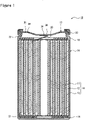
FIG. 1 is a sectional view of a sealedbattery 10 that is an example of an embodiment. As illustrated inFIG. 1 , a sealedbattery 10 comprises anelectrode assembly 14, a bottomed tubular outer housing can 16 for accommodating theelectrode assembly 14, and asealing assembly 17 that closes the opening of the outer housing can 16. An electrolyte is accommodated in the outer housing can 16. Theelectrode assembly 14 includes a positive electrode 11, anegative electrode 12, and aseparator 13 interposed between the positive electrode 11 and thenegative electrode 12 and has apositive electrode tab 20 and anegative electrode tab 21 as electrode tabs. The electrode tab is generally formed of a strip-shaped metal plate having a thickness larger than that of the core of the electrode. Theelectrode assembly 14 has a wound structure in which the positive electrode 11 and thenegative electrode 12 are wound with theseparator 13 interposed therebetween. - The electrolyte may be either an aqueous electrolyte or a non-aqueous electrolyte. An example of the suitable sealed
battery 10 is a non-aqueous electrolyte secondary battery using a non-aqueous electrolyte, such as a lithium-ion battery. The non-aqueous electrolyte includes, for example, a non-aqueous solvent and an electrolyte salt dissolved in the non-aqueous solvent. As the non-aqueous solvent, esters, ethers, nitriles, amides, or a mixed solvent of two or more of them may be used. The non-aqueous solvent may contain a halogen substitution in which at least a part of hydrogen in the solvent is substituted with a halogen atom such as fluorine. Note that the non-aqueous electrolyte is not limited to a liquid electrolyte but may be a solid electrolyte. As the electrolyte salt, for example, a lithium salt such as LiPF6 is used. - The
electrode assembly 14 includes the elongated positive electrode 11, the elongatednegative electrode 12, twoelongated separators 13, thepositive electrode tab 20 joined to the positive electrode 11, and thenegative electrode tab 21 joined to thenegative electrode 12. Thenegative electrode 12 is formed to have a size larger than that of the positive electrode 11 in order to prevent the precipitation of lithium. That is, thenegative electrode 12 is formed to be longer than the positive electrode 11 in the longitudinal direction and the shorter direction (vertical direction). The twoseparators 13 are formed to have at least one size larger than the positive electrode 11 and are disposed to sandwich the positive electrode 11, for example. - The positive electrode 11 has a positive electrode core and positive electrode mixture layers provided on both sides of the positive electrode core. As the positive electrode core, it is possible to use a foil of a metal stable in the potential range of the positive electrode 11, such as aluminum or an aluminum alloy, a film in which the metal is disposed on the surface layer, or the like. The positive electrode mixture layer includes a positive electrode active material, a conductive agent such as acetylene black, and a binder such as a polyvinylidene fluoride (PVdF). The positive electrode 11 can be produced by coating a positive electrode mixture slurry including a positive electrode active material, a conductive agent, a binder, and the like on the positive electrode core, drying the coating film, and then compressing the coating film to form positive electrode mixture layers on both sides of the positive electrode core.
- As the positive electrode active material, for example, a lithium transition metal complex oxide is used. Examples of the metal element contained in the lithium transition metal complex oxide include Ni, Co, Mn, Al, B, Mg, Ti, V, Cr, Fe, Cu, Zn, Ga, Sr, Zr, Nb, In, Sn, Ta, W, and the like. An example of a suitable lithium transition metal complex oxide is a lithium metal complex oxide containing at least one of Ni, Co, and Mn. Specific examples include composite oxides containing Ni, Co, and Mn and composite oxides containing Ni, Co, and Al.
- The
negative electrode 12 has a negative electrode core and negative electrode mixture layers provided on both surfaces of the negative electrode core. As the negative electrode core, it is possible to use a foil of a metal stable in the potential range of thenegative electrode 12, such as copper or copper alloy, a film in which the metal is disposed on the surface layer, or the like. The negative electrode mixture layer includes a negative electrode active material and a binder such as styrene-butadiene rubber (SBR). Thenegative electrode 12 can be produced by applying a negative electrode mixture slurry including a negative electrode active material, a binder, and the like on the negative electrode core, drying the coating film, and then compressing the coating film to form negative electrode mixture layers on both sides of the negative electrode core. - As the negative electrode active material, for example, a carbon-based active material is used, which is natural graphite such as scaly graphite, massive graphite, or earthy graphite, artificial graphite such as massive artificial graphite or graphitized mesophase carbon microbeads, or the like. As the negative electrode active material, an element which is alloyed with lithium, such as Si and Sn, an alloy containing the element, a compound containing the element, or the like may be used, and these may be used in combination with the carbon-based active material.
-
Insulating plates electrode assembly 14, respectively. In the example illustrated inFIG. 1 , thepositive electrode tab 20 attached to the positive electrode 11 passes through the through hole of the insulatingplate 18 and extends toward the sealingassembly 17, and thenegative electrode tab 21 attached to thenegative electrode 12 passes through the outside of the insulatingplate 19 and extends to the bottom side of the outer housing can 16. Thepositive electrode tab 20 is connected to the inner surface of the sealingassembly 17 facing the inside of the battery by welding or the like, and the sealingassembly 17 serves as a positive electrode external terminal. Thenegative electrode tab 21 is connected to the bottom inner surface of the outer housing can 16 by welding or the like, and the outer housing can 16 serves as a negative electrode external terminal. Note that thenegative electrode tab 21 may be connected to the inner surface of the sealingassembly 17, and in this case, the sealingassembly 17 serves as a negative electrode external terminal. - The outer housing can 16 is, for example, a metal container having a bottomed cylindrical shape. A
resin gasket 23 is provided between the outer housing can 16 and the sealingassembly 17. A gap between the outer housing can 16 and the sealingassembly 17 is closed by agasket 23, and the inside of the battery is sealed hermetically. The outer housing can 16 has a groovedportion 22 formed on a side surface portion by spinning from the outside of the side surface portion, for example, and supports the sealingassembly 17. The groovedportion 22 is preferably formed in an annular shape along the circumferential direction of the outer housing can 16 and supports the sealingassembly 17 on the upper surface of the outer housing can 16. The upper end of the outer housing can 16 is bent inward of the can and caulked to the periphery of the sealingassembly 17. - Hereinafter, the sealing
assembly 17 will be described in detail with further reference toFIGS. 2 to 4 .FIG. 2 is a bottom view of the sealingassembly 17, andFIG. 3 is a sectional view taken along line AA inFIG. 2 . - As illustrated in
FIGS. 2 and 3 , the sealingassembly 17 has a firstthin portion 34 formed in an annular shape. The sealingassembly 17 has avalve portion 30 surrounded by the firstthin portion 34, anannular portion 31 located outside the firstthin portion 34, and a linear secondthin portion 36 formed in thevalve portion 30. Thevalve portion 30 is a portion that is deformed so as to protrude outward of the battery when an abnormality occurs in the battery and the internal pressure rises. The firstthin portion 34 is a portion having a thickness smaller than the valve portion 30 (excluding a portion where the secondthin portion 36 is formed) and theannular portion 31, and serving as a starting point of deformation of thevalve portion 30 when the internal pressure rises. - The sealing
assembly 17 is fixed to the outer housing can 16 by theannular portion 31 being held between the upper end of the outer housing can 16 and the groovedportion 22 via thegasket 23. On the other hand, thevalve portion 30 is not held between the upper end of the outer housing can 16 and the groovedportion 22 and is deformable when the internal pressure rises. The sealingassembly 17 is formed of a single metal plate including thevalve portion 30 and theannular portion 31 divided by the firstthin portion 34. Therefore, the sealingassembly 17 has advantages such as a small thickness, a simple structure, and a small number of parts. - In the sealed
battery 10, thepositive electrode tab 20 is joined to the inner surface of thevalve portion 30 by welding or the like. External wiring connected to an electric product (not illustrated), another sealedbattery 10, or the like is connected to the outer surface of the sealingassembly 17 by welding or the like. Note that the external wiring may be connected to either thevalve portion 30 or theannular portion 31 as long as being located so as not to prevent the inversion or breakage of thevalve portion 30. - The
valve portion 30 has a downward convex shape protruding inward of the battery and is configured to protrude outward of the battery when the internal pressure rises. As will be described in detail later, when the internal pressure reaches a predetermined pressure, thevalve portion 30 is inverted so as to have an upward convex shape protruding outward of the battery. Then, the secondthin portion 36 is broken to form an exhaust port, and thepositive electrode tab 20 is detached from thevalve portion 30 to cut off the current path of the battery. After the inversion of thevalve portion 30 and before the breakage of the secondthin portion 36, thepositive electrode tab 20 may be detached from thevalve portion 30 to cut off the current path. - The metal plate constituting the sealing
assembly 17 is, for example, an aluminum alloy plate containing aluminum as a main component. The thickness of the metal plate is not particularly limited, but as an example, the thickness is 0.3 mm to 2 mm in a portion except for the firstthin portion 34 and the secondthin portion 36. The thicknesses of thevalve portion 30 and theannular portion 31 may be the same or different. The sealingassembly 17 is manufactured, for example, by forming the annular firstthin portion 34 and the linear secondthin portion 36 on the single metal plate and pressing thevalve portion 30 surrounded by the firstthin portion 34 into a downward convex shape. - In the present embodiment, the annular first
thin portion 34 is formed by the annularfirst groove 35. Thefirst groove 35 is formed on the inner surface of the sealingassembly 17 but can be formed on the outer surface of the sealingassembly 17. The thickness of the firstthin portion 34 is, for example, 10% to 50% of the maximum thickness of thevalve portion 30 and can be adjusted by changing the depth of thefirst groove 35. The firstthin portion 34 is preferably formed thicker than the secondthin portion 36. - The first thin portion 34 (first groove 35) is preferably formed in a circular shape without corners in bottom view, and particularly preferably formed in a substantially perfect circular shape as illustrated in
FIG. 2 . Here, the term "substantially perfect circular shape" means a perfect circular shape or a shape recognized as a substantially perfect circle. Thefirst groove 35 illustrated inFIG. 3 is formed in a substantially triangular shape in cross section, but the sectional shape of thefirst groove 35 is not limited to a triangular shape but may be, for example, a semicircular shape or a quadrangular shape. - Note that the first
thin portion 34 is not limited to the linear thin portion formed by thefirst groove 35 but may be, for example, a wide thin portion in which the thickness of the metal plate continuously decreases from the inner side to the outer side of the sealingassembly 17 in the radial direction. - The
valve portion 30 preferably has a substantially perfect circular shape in bottom view. In this case, thevalve portion 30 is smoothly inverted when the internal pressure rises. As described above, thevalve portion 30 and theannular portion 31 are separated by the first thin portion 34 (first groove 35), so that the shapes of thevalve portion 30 and theannular portion 31 in bottom view are determined by the shape of the firstthin portion 34 in bottom view. When thevalve portion 30 has a perfect circular shape in bottom view, theannular portion 31 is formed in an annular shape in bottom view. - A diameter d of the
valve portion 30 is, for example, 50% to 90%, preferably 55% to 85%, of a diameter D of the sealingassembly 17. When "diameter d / diameter D" is within this range, the sealingassembly 17 can be stably fixed to the outer housing can 16, and at the time of occurrence of an abnormality, a large exhaust port can be formed, and gas can be discharged smoothly. - The
valve portion 30 has a downward convex shape protruding inward in a normal use state in which the internal pressure of the battery is low. That is, thevalve portion 30 is recessed inward as viewed from the outside of the battery. Thevalve portion 30 bulges toward theelectrode assembly 14 in a range where thevalve portion 30 is not in contact with theelectrode assembly 14. The shape of thevalve portion 30 is not particularly limited as long as being deformable into an upward convex shape by internal pressure. However, the shape of thevalve portion 30 is preferably a shape that can be inverted from a downward convex shape to an upward convex shape, and may be, for example, a shape formed by thewhole valve portion 30 being curved in a dome shape. - In the present embodiment, the
valve portion 30 has a flat bottom 32 that bulges most toward theelectrode assembly 14, and an annularinclined portion 33 formed around the bottom 32. In the example illustrated inFIG. 3 , theinclined portion 33 is formed to have a constant gradient from the bottom 32 toward theannular portion 31, and a bent portion exists at the boundary between the bottom 32 and theinclined portion 33. The bottom 32 is formed substantially in parallel with theannular portion 31 and disposed substantially in parallel with the bottom of the outer housing can 16. The bottom 32 has a substantially perfect circular shape in bottom view, and theinclined portion 33 is formed in an annular shape in bottom view so as to surround the bottom 32. - As described above, the linear second
thin portion 36 is formed in thevalve portion 30. The secondthin portion 36 is thinner than the firstthin portion 34 and breaks preferentially over the firstthin portion 34 when the internal pressure rises due to, for example, an abnormality of the battery. The secondthin portion 36 is formed only on thevalve portion 30. The sealingassembly 17 is configured such that an exhaust port is formed by the breakage of the secondthin portion 36. - The second
thin portion 36 is formed by a linearsecond groove 37. Thesecond groove 37 preferably has the shape of a straight line but may be slightly bent as long as having the shape of a line. Thesecond groove 37 is formed on the inner surface of thevalve portion 30 but can be formed on the outer surface. The thickness of the secondthin portion 36 is, for example, 30% to 90%, preferably 50% to 80%, of the maximum thickness of thevalve portion 30 and can be adjusted by changing the depth of thesecond groove 37. - In the present embodiment, one second
thin portion 36 is formed along the radial direction of the firstthin portion 34 passing through a center α of the firstthin portion 34 formed in the annular shape, that is, a center α of thevalve portion 30. Stress is concentrated in the central portion of thevalve portion 30 at the time of deformation of thevalve portion 30, so that when the secondthin portion 36 is formed to pass through the center α, the secondthin portion 36 is easily broken with the deformation of thevalve portion 30. The secondthin portion 36 is formed over the entire radial length of thevalve portion 30 and is connected to the firstthin portion 34. Thesecond groove 37 illustrated inFIG. 3 is formed in a substantially triangular shape in cross section, but thesecond groove 37 may be formed in a semicircular shape or a quadrangular shape, for example. - In order to break the second thin portion 36 (second groove 37) preferentially over the first thin portion 34 (first groove 35), the shapes of the grooves forming the respective thin portions may be made different from each other. For example, the
first groove 35 may have a semicircular shape in cross section, and thesecond groove 37 may have a triangular shape in cross section. Alternatively, each of the grooves may have a triangular shape in cross section, and an angle θ of the triangle at the depth of the groove may be made different. For example, two or more secondthin portions 36 may be formed in a range where the joining of thepositive electrode tab 20 is not hindered, or may be formed in a cross shape so as to intersect at the center α of thevalve portion 30. - In the sealed
battery 10, thepositive electrode tab 20 is disposed to intersect the secondthin portion 36 and is joined to the inner surface of thevalve portion 30 by welding or the like so as to sandwich the secondthin portion 36. Thepositive electrode tab 20 overlaps the secondthin portion 36 in the vertical direction and intersects the secondthin portion 36 as viewed from the bottom of the sealingassembly 17. Note that the leading end of thepositive electrode tab 20 is bent along the bottom 32 of thevalve portion 30 and is in contact with the inner surface of the bottom 32. In order not to inhibit the deformation of thevalve portion 30, it is preferable that the leading end of thepositive electrode tab 20 be disposed not to project from the bottom 32, and the bent portion of thepositive electrode tab 20 be formed in a range overlapping the bottom 32. - In the example illustrated in
FIG. 2 , the leading end of thepositive electrode tab 20 along the bottom 32 is disposed to be orthogonal to the second thin portion 36 (second groove 37) at the center α of thevalve portion 30. Thepositive electrode tab 20 is welded to the inner surface of the bottom 32 of thevalve portion 30, which is a portion separated radially outward of thevalve portion 30 by a predetermined length from both ends in the width direction of thesecond groove 37. As will be described in detail later, since thepositive electrode tab 20 intersects the secondthin portion 36 and is welded to thevalve portion 30 so as to sandwich the secondthin portion 36, when thevalve portion 30 is inverted and the secondthin portion 36 is broken, thewelding portion 25 of thepositive electrode tab 20 is broken to cut off the current path of the battery. - On the inner surface of the
valve portion 30, thewelding portions 25 are formed at least two locations on both sides in the width direction of thesecond groove 37. For example, the length from thesecond groove 37 to eachwelding portion 25 is substantially the same, and each weldingportion 25 is formed to have substantially the same size. In this case, when the secondthin portion 36 is broken, the twowelding portions 25 are likely to be broken simultaneously. The length from thesecond groove 37 to thewelding portion 25 is, for example, 50% or less, preferably 30% or less, and more preferably 20% or less, of the radius of thevalve portion 30. Thewelding portion 25 is preferably formed in the vicinity of thesecond groove 37 in a range not overlapping thesecond groove 37. - The
positive electrode tab 20 is preferably disposed at the center α of thevalve portion 30 as described above. The twowelding portions 25 formed on both sides in the width direction of thesecond groove 37 are preferably aligned in the radial direction of thevalve portion 30. In this case, when thevalve portion 30 is inverted and the secondthin portion 36 is broken, the twowelding portions 25 are likely to be broken simultaneously. When thepositive electrode tab 20 is directly welded to the inner surface of thevalve portion 30, it is preferable that thepositive electrode tab 20 and thesecond groove 37 be substantially orthogonal to each other as viewed from the bottom of the sealingassembly 17. -
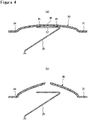
FIG. 4 is a view illustrating a state in which the sealingassembly 17 comprising the above configuration is inverted and broken. When the internal pressure rises due to an abnormality of the sealedbattery 10, as illustrated inFIG. 4(a) , thevalve portion 30 having a downward convex shape protruding inward of the battery is inverted with the firstthin portion 34 as a starting point and becomes an upward convex shape protruding outward of the battery. At this time, in the example illustrated inFIG. 4(a) , thewelding portion 25 of thepositive electrode tab 20 is not broken, and the sealingassembly 17 and thepositive electrode tab 20 are in an electrically connected state. - When the internal pressure of the battery further rises, as illustrated in
FIG. 4(b) , the linear secondthin portion 36 formed in thevalve portion 30 is broken. An exhaust port through which the gas is discharged is formed in thevalve portion 30, and thepositive electrode tab 20 is detached from thevalve portion 30 to cut off the current path of the battery. Since thepositive electrode tab 20 is welded to the inner surface of thevalve portion 30 so as to sandwich the secondthin portion 36, when the secondthin portion 36 is broken and thevalve portion 30 opens, thewelding portion 25 is strongly pulled upward and radially outward of the sealingassembly 17, whereby thewelding portion 25 is broken. - In the example illustrated in
FIG. 4 , the breakage of the secondthin portion 36 has led to the breakage of thewelding portion 25 to cut off the current path. However, the current path may be cut off when thevalve portion 30 is inverted and becomes an upward convex shape, and then the secondthin portion 36 may be broken to form the exhaust port. - With reference to
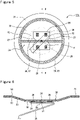
FIGS. 5 to 7 , a sealingassembly 17x as another example of the embodiment will be described in detail below.FIG. 5 is a bottom view of the sealingassembly 17x, andFIG. 6 is a sectional view taken along line BB inFIG. 5 . In the following description, the same reference numerals are used for the same components as those in the embodiment described above, and the redundant description thereof is omitted. - As illustrated in
FIGS. 5 and 6 , the sealingassembly 17x differs from the sealingassembly 17 in which thepositive electrode tab 20 is directly welded to the inner surface of thevalve portion 30 in that the sealingassembly 17x includes atab welding plate 26 joined to the inner surface of thevalve portion 30 and that thepositive electrode tab 20 is electrically connected to thevalve portion 30 via thetab welding plate 26. Thetab welding plate 26 is a metal plate disposed to intersect the secondthin portion 36. In the present embodiment, thetab welding plate 26 is welded to portions located on both sides of the secondthin portion 36 so as to sandwich the secondthin portion 36 with respect to the inner surface of thevalve portion 30, and thepositive electrode tab 20 is welded to the lower surface of thetab welding plate 26. In the example illustrated inFIG. 5 , awelding portion 29 of thepositive electrode tab 20 to thetab welding plate 26 is formed at a position overlapping the center α of thevalve portion 30. - When the
positive electrode tab 20 is directly welded to the inner surface of thevalve portion 30, by welding thepositive electrode tab 20 so as to be orthogonal to the secondthin portion 36, the secondthin portion 36 is easily broken when the internal pressure rises, and the current path is easily cut off. For this reason, thepositive electrode tab 20 is preferably aligned so as to be orthogonal to the secondthin portion 36, but the use of thetab welding plate 26 eliminates the need for such alignment. That is, when thetab welding plate 26 is welded in advance so as to sandwich the secondthin portion 36, thepositive electrode tab 20 may be welded to thetab welding plate 26 without concern for the direction of thepositive electrode tab 20 with respect to the secondthin portion 36. - The
tab welding plate 26 may be a metal plate having a size capable of being disposed across the second thin portion 36 (second groove 37) and capable of welding thepositive electrode tab 20, and the shape of thetab welding plate 26 is not particularly limited. However, thetab welding plate 26 is preferably smaller than the bottom 32 of thevalve portion 30 so as not to inhibit the deformation of thevalve portion 30. Further, thetab welding plate 26 is preferably broken together with the secondthin portion 36, and for example, thetab welding plate 26 has a thickness similar to that of the secondthin portion 36. - In the example illustrated in
FIG. 5 , a substantially quadrangulartab welding plate 26 is disposed at the center α of thevalve portion 30, and thewelding portions 28 are formed at four corners of thetab welding plate 26 so as to sandwich thesecond groove 37. Eachwelding portion 28 is formed, for example, at a position substantially equidistant from the center α of thevalve portion 30. Thewelding portions 28 formed on both sides in the width direction of thesecond groove 37 are aligned in the radial direction of thevalve portion 30. - Two
notches 27 are formed in thetab welding plate 26 at positions overlapping thesecond groove 37. The twonotches 27 are formed on two sides of the quadrangle opposite to each other while being aligned in a direction in which the secondthin portion 36 extends, and the twonotches 27 serve as starting points when thetab welding plate 26 is broken. In the example illustrated inFIG. 5 , thenotch 27 having a triangular shape in bottom view is formed, and thetab welding plate 26 is disposed such that the apex of thenotch 27 overlaps thesecond groove 37. In thetab welding plate 26, a thin portion may be formed in a portion substantially overlapping the secondthin portion 36 along the direction in which the secondthin portion 36 extends, or a thin portion may be formed so as to connect the twonotches 27. -
FIG. 7 is a view illustrating a state in which the sealingassembly 17x comprising the above configuration is inverted and broken. When the internal pressure rises due to an abnormality of the sealedbattery 10, as illustrated inFIG. 7(a) , thevalve portion 30 is inverted with the firstthin portion 34 as a starting point and becomes an upward convex shape. When the internal pressure of the battery further rises, as illustrated inFIG. 7(b) , thetab welding plate 26 is broken at the same time as the secondthin portion 36 is broken. Then, an exhaust port for releasing the gas is formed in thevalve portion 30, and thepositive electrode tab 20 is detached from thetab welding plate 26 to cut off the current path of the battery. - In the example illustrated in
FIG. 7 , thewelding portion 29 has been broken by the breakage of thetab welding plate 26 to cut off the current path. However, when thevalve portion 30 is inverted and becomes an upward convex shape, thewelding portion 29 may be broken, and thepositive electrode tab 20 may be detached from thetab welding plate 26. - As described above, the sealing
assemblies sealing assemblies battery 10 can be reduced, and the energy density can be improved. - Note that the design of the embodiment described above can be appropriately modified to the extent that the object of the present disclosure is not impaired. For example, in the embodiment described above, the sealing
assemblies convex valve portion 30 have been exemplified, but the valve member may not have a downward convex shape, and the sealing assembly may have a flat disk shape. Thetab welding plate 26 having twonotches 27 has been exemplified, but the number ofnotches 27 may be one. Alternatively, instead of thetab welding plate 26, a metal plate without thenotch 27 may be used. - 10 sealed battery, 11 positive electrode, 12 negative electrode, 13 separator, 14 electrode assembly, 16 outer housing can, 17, 17x sealing assembly, 18, 19 insulating plate, 20 positive electrode tab, 21 negative electrode tab, 22 grooved portion, 23 gasket, 25, 28, 29 welding portion, 26 tab welding plate, 27 notch, 30 valve portion, 31 annular portion, 32 bottom, 33 inclined portion, 34 first thin portion, 35 first groove, 36 second thin portion, 37 second groove
Claims (5)
- A sealed battery comprising:an electrode assembly having an electrode tab;an outer housing can in a shape of a bottomed cylinder that accommodates the electrode assembly; anda sealing assembly that closes an opening of the outer housing can, whereinthe sealing assembly includesa first thin portion formed in an annular shape,a valve portion that is surrounded by the first thin portion, and deforms to protrude outward of the battery when internal pressure of the battery rises, anda second thin portion in a linear shape formed in the valve portion, andthe electrode tab or a metal plate to which the electrode tab is connected is disposed to intersect the second thin portion and is joined to an inner surface of the valve portion to sandwich the second thin portion.
- The sealed battery according to claim 1, whereinthe first thin portion is formed in an annular shape by an annular groove, andthe second thin portion passes through a center of the first thin portion and is formed in a linear shape along a radial direction of the first thin portion.
- The sealed battery according to claim 1 or 2, wherein the second thin portion is thinner than the first thin portion.
- The sealed battery according to any one of claims 1 to 3, wherein the valve portion has a shape protruding inward of the battery, and is configured to protrude outward of the battery when the internal pressure rises.
- The sealed battery according to any one of claims 1 to 4, wherein a notch is formed in the metal plate at a position overlapping the second thin portion.
Applications Claiming Priority (2)
| Application Number | Priority Date | Filing Date | Title |
|---|---|---|---|
| JP2020039764 | 2020-03-09 | ||
| PCT/JP2021/006491 WO2021182080A1 (en) | 2020-03-09 | 2021-02-19 | Hermetically sealed battery |
Publications (2)
| Publication Number | Publication Date |
|---|---|
| EP4120447A1 true EP4120447A1 (en) | 2023-01-18 |
| EP4120447A4 EP4120447A4 (en) | 2023-12-13 |
Family
ID=77670686
Family Applications (1)
| Application Number | Title | Priority Date | Filing Date |
|---|---|---|---|
| EP21767741.8A Pending EP4120447A4 (en) | 2020-03-09 | 2021-02-19 | Hermetically sealed battery |
Country Status (5)
| Country | Link |
|---|---|
| US (1) | US20230098011A1 (en) |
| EP (1) | EP4120447A4 (en) |
| JP (1) | JP7664220B2 (en) |
| CN (1) | CN115176377B (en) |
| WO (1) | WO2021182080A1 (en) |
Families Citing this family (2)
| Publication number | Priority date | Publication date | Assignee | Title |
|---|---|---|---|---|
| CN118216036A (en) * | 2022-06-10 | 2024-06-18 | 宁德时代新能源科技股份有限公司 | Battery cells, batteries and electrical equipment |
| KR20250137233A (en) * | 2024-03-11 | 2025-09-18 | 삼성에스디아이 주식회사 | Cylindrical secondary battery |
Family Cites Families (22)
| Publication number | Priority date | Publication date | Assignee | Title |
|---|---|---|---|---|
| JPH0574432A (en) * | 1991-09-09 | 1993-03-26 | Asahi Chem Ind Co Ltd | Explosion-proof enclosed battery |
| JP3511698B2 (en) * | 1994-11-29 | 2004-03-29 | 宇部興産株式会社 | Sealed non-aqueous secondary battery |
| JP2001102038A (en) * | 1999-10-01 | 2001-04-13 | Toyo Kohan Co Ltd | Safety device for sealed battery and lead mounting plate in the device |
| KR100342052B1 (en) | 1999-10-27 | 2002-06-27 | 김순택 | Sealed battery |
| JP4155734B2 (en) * | 2001-12-20 | 2008-09-24 | 三洋電機株式会社 | Battery safety valve |
| JP5011664B2 (en) * | 2005-07-11 | 2012-08-29 | パナソニック株式会社 | Sealed secondary battery |
| JP2009140870A (en) * | 2007-12-10 | 2009-06-25 | Sanyo Electric Co Ltd | Terminal for sealed battery, and sealed battery |
| CN201355616Y (en) * | 2009-01-22 | 2009-12-02 | 陶京 | Protection device for cylindrical lithium batteries |
| US20100215997A1 (en) * | 2009-02-25 | 2010-08-26 | Samsung Sdi Co., Ltd. | Rechargeable battery |
| WO2014045569A1 (en) * | 2012-09-24 | 2014-03-27 | 三洋電機株式会社 | Sealed secondary battery |
| WO2014119308A1 (en) * | 2013-01-31 | 2014-08-07 | 三洋電機株式会社 | Sealed battery |
| KR101514827B1 (en) * | 2013-02-26 | 2015-04-23 | 주식회사 엘지화학 | Secondary battery and method for manufacturing the same |
| JP2014197463A (en) | 2013-03-29 | 2014-10-16 | 三洋電機株式会社 | Battery |
| CN106030850B (en) * | 2014-03-28 | 2019-11-12 | 三洋电机株式会社 | Cylindrical sealed battery |
| JP2018014160A (en) | 2014-11-27 | 2018-01-25 | 三洋電機株式会社 | Cylindrical nonaqueous electrolyte secondary battery |
| CN205595397U (en) * | 2016-04-18 | 2016-09-21 | 江阴市瑞鸿电子有限公司 | Baffle of explosion -proof combined cover cap of cylinder type lithium cell |
| WO2018030836A1 (en) * | 2016-08-11 | 2018-02-15 | Shin Heung Energy & Electronic Co.,Ltd. | Cap assembly for secondary battery and secondary battery including the cap assembly |
| CN106450063B (en) * | 2016-11-15 | 2019-07-19 | 宁德时代新能源科技股份有限公司 | Secondary battery |
| JP2018200826A (en) * | 2017-05-29 | 2018-12-20 | 三洋電機株式会社 | Cylindrical battery |
| JP7025861B2 (en) * | 2017-08-22 | 2022-02-25 | 大和製罐株式会社 | Seal plate |
| CN207676956U (en) * | 2017-12-13 | 2018-07-31 | 深圳市比克动力电池有限公司 | Caps for cylindrical lithium-ion batteries |
| US11393643B2 (en) * | 2018-09-28 | 2022-07-19 | Taiyo Yuden Co., Ltd. | Electrochemical device and method of producing the same |
-
2021
- 2021-02-19 US US17/908,464 patent/US20230098011A1/en active Pending
- 2021-02-19 CN CN202180017051.3A patent/CN115176377B/en active Active
- 2021-02-19 EP EP21767741.8A patent/EP4120447A4/en active Pending
- 2021-02-19 WO PCT/JP2021/006491 patent/WO2021182080A1/en not_active Ceased
- 2021-02-19 JP JP2022505888A patent/JP7664220B2/en active Active
Also Published As
| Publication number | Publication date |
|---|---|
| JP7664220B2 (en) | 2025-04-17 |
| US20230098011A1 (en) | 2023-03-30 |
| JPWO2021182080A1 (en) | 2021-09-16 |
| EP4120447A4 (en) | 2023-12-13 |
| WO2021182080A1 (en) | 2021-09-16 |
| CN115176377B (en) | 2024-06-11 |
| CN115176377A (en) | 2022-10-11 |
Similar Documents
| Publication | Publication Date | Title |
|---|---|---|
| CN113302786B (en) | sealed battery | |
| US20190221824A1 (en) | Non-aqueous electrolyte secondary battery | |
| EP4068443A1 (en) | Sealed battery | |
| US20220069408A1 (en) | Sealed battery | |
| JP7422680B2 (en) | Gasket and cylindrical battery | |
| US12237518B2 (en) | Cylindrical battery | |
| JP2014096225A (en) | Square secondary battery | |
| US12567629B2 (en) | Sealed battery | |
| JPWO2016009586A1 (en) | Power storage device | |
| EP4318768A1 (en) | Sealed battery | |
| WO2017098690A1 (en) | Cell | |
| EP4120447A1 (en) | Hermetically sealed battery | |
| US20240039096A1 (en) | Gasket and cylindrical battery | |
| EP3902024B1 (en) | Sealed battery | |
| US20250273834A1 (en) | Cylindrical battery | |
| WO2023189790A1 (en) | Cylindrical battery | |
| WO2023176511A1 (en) | Cylindrical battery | |
| EP4456280A1 (en) | Cylindrical battery | |
| EP4693641A1 (en) | Cylindrical battery and method for manufacturing cylindrical battery | |
| EP4661147A1 (en) | Cylindrical non-aqueous electrolyte secondary battery | |
| WO2024185394A1 (en) | Gasket, cylindrical battery, and cylindrical battery manufacturing method | |
| WO2024161974A1 (en) | Cylindrical battery | |
| WO2024048145A1 (en) | Cylindrical battery | |
| WO2024048147A1 (en) | Cylindrical battery | |
| CN120513548A (en) | Cylindrical batteries |
Legal Events
| Date | Code | Title | Description |
|---|---|---|---|
| STAA | Information on the status of an ep patent application or granted ep patent |
Free format text: STATUS: THE INTERNATIONAL PUBLICATION HAS BEEN MADE |
|
| PUAI | Public reference made under article 153(3) epc to a published international application that has entered the european phase |
Free format text: ORIGINAL CODE: 0009012 |
|
| STAA | Information on the status of an ep patent application or granted ep patent |
Free format text: STATUS: REQUEST FOR EXAMINATION WAS MADE |
|
| 17P | Request for examination filed |
Effective date: 20220825 |
|
| AK | Designated contracting states |
Kind code of ref document: A1 Designated state(s): AL AT BE BG CH CY CZ DE DK EE ES FI FR GB GR HR HU IE IS IT LI LT LU LV MC MK MT NL NO PL PT RO RS SE SI SK SM TR |
|
| DAV | Request for validation of the european patent (deleted) | ||
| DAX | Request for extension of the european patent (deleted) | ||
| REG | Reference to a national code |
Ref country code: DE Ref legal event code: R079 Free format text: PREVIOUS MAIN CLASS: H01M0050147000 Ipc: H01M0050107000 |
|
| A4 | Supplementary search report drawn up and despatched |
Effective date: 20231115 |
|
| RIC1 | Information provided on ipc code assigned before grant |
Ipc: H01M 50/578 20210101ALI20231109BHEP Ipc: H01M 50/534 20210101ALI20231109BHEP Ipc: H01M 50/342 20210101ALI20231109BHEP Ipc: H01M 50/152 20210101ALI20231109BHEP Ipc: H01M 50/107 20210101AFI20231109BHEP |