EP4120439A1 - Structural battery comprising cooling channels - Google Patents
Structural battery comprising cooling channels Download PDFInfo
- Publication number
- EP4120439A1 EP4120439A1 EP21186238.8A EP21186238A EP4120439A1 EP 4120439 A1 EP4120439 A1 EP 4120439A1 EP 21186238 A EP21186238 A EP 21186238A EP 4120439 A1 EP4120439 A1 EP 4120439A1
- Authority
- EP
- European Patent Office
- Prior art keywords
- transverse beam
- bracket
- extending
- battery
- situated
- Prior art date
- Legal status (The legal status is an assumption and is not a legal conclusion. Google has not performed a legal analysis and makes no representation as to the accuracy of the status listed.)
- Granted
Links
Images


Classifications
-
- B—PERFORMING OPERATIONS; TRANSPORTING
- B60—VEHICLES IN GENERAL
- B60L—PROPULSION OF ELECTRICALLY-PROPELLED VEHICLES; SUPPLYING ELECTRIC POWER FOR AUXILIARY EQUIPMENT OF ELECTRICALLY-PROPELLED VEHICLES; ELECTRODYNAMIC BRAKE SYSTEMS FOR VEHICLES IN GENERAL; MAGNETIC SUSPENSION OR LEVITATION FOR VEHICLES; MONITORING OPERATING VARIABLES OF ELECTRICALLY-PROPELLED VEHICLES; ELECTRIC SAFETY DEVICES FOR ELECTRICALLY-PROPELLED VEHICLES
- B60L50/00—Electric propulsion with power supplied within the vehicle
- B60L50/50—Electric propulsion with power supplied within the vehicle using propulsion power supplied by batteries or fuel cells
- B60L50/60—Electric propulsion with power supplied within the vehicle using propulsion power supplied by batteries or fuel cells using power supplied by batteries
- B60L50/66—Arrangements of batteries
-
- B—PERFORMING OPERATIONS; TRANSPORTING
- B60—VEHICLES IN GENERAL
- B60K—ARRANGEMENT OR MOUNTING OF PROPULSION UNITS OR OF TRANSMISSIONS IN VEHICLES; ARRANGEMENT OR MOUNTING OF PLURAL DIVERSE PRIME-MOVERS IN VEHICLES; AUXILIARY DRIVES FOR VEHICLES; INSTRUMENTATION OR DASHBOARDS FOR VEHICLES; ARRANGEMENTS IN CONNECTION WITH COOLING, AIR INTAKE, GAS EXHAUST OR FUEL SUPPLY OF PROPULSION UNITS IN VEHICLES
- B60K1/00—Arrangement or mounting of electrical propulsion units
- B60K1/04—Arrangement or mounting of electrical propulsion units of the electric storage means for propulsion
-
- B—PERFORMING OPERATIONS; TRANSPORTING
- B60—VEHICLES IN GENERAL
- B60L—PROPULSION OF ELECTRICALLY-PROPELLED VEHICLES; SUPPLYING ELECTRIC POWER FOR AUXILIARY EQUIPMENT OF ELECTRICALLY-PROPELLED VEHICLES; ELECTRODYNAMIC BRAKE SYSTEMS FOR VEHICLES IN GENERAL; MAGNETIC SUSPENSION OR LEVITATION FOR VEHICLES; MONITORING OPERATING VARIABLES OF ELECTRICALLY-PROPELLED VEHICLES; ELECTRIC SAFETY DEVICES FOR ELECTRICALLY-PROPELLED VEHICLES
- B60L3/00—Electric devices on electrically-propelled vehicles for safety purposes; Monitoring operating variables, e.g. speed, deceleration or energy consumption
- B60L3/0007—Measures or means for preventing or attenuating collisions
-
- B—PERFORMING OPERATIONS; TRANSPORTING
- B60—VEHICLES IN GENERAL
- B60L—PROPULSION OF ELECTRICALLY-PROPELLED VEHICLES; SUPPLYING ELECTRIC POWER FOR AUXILIARY EQUIPMENT OF ELECTRICALLY-PROPELLED VEHICLES; ELECTRODYNAMIC BRAKE SYSTEMS FOR VEHICLES IN GENERAL; MAGNETIC SUSPENSION OR LEVITATION FOR VEHICLES; MONITORING OPERATING VARIABLES OF ELECTRICALLY-PROPELLED VEHICLES; ELECTRIC SAFETY DEVICES FOR ELECTRICALLY-PROPELLED VEHICLES
- B60L50/00—Electric propulsion with power supplied within the vehicle
- B60L50/50—Electric propulsion with power supplied within the vehicle using propulsion power supplied by batteries or fuel cells
- B60L50/60—Electric propulsion with power supplied within the vehicle using propulsion power supplied by batteries or fuel cells using power supplied by batteries
- B60L50/64—Constructional details of batteries specially adapted for electric vehicles
-
- H—ELECTRICITY
- H01—ELECTRIC ELEMENTS
- H01M—PROCESSES OR MEANS, e.g. BATTERIES, FOR THE DIRECT CONVERSION OF CHEMICAL ENERGY INTO ELECTRICAL ENERGY
- H01M10/00—Secondary cells; Manufacture thereof
- H01M10/60—Heating or cooling; Temperature control
- H01M10/61—Types of temperature control
- H01M10/613—Cooling or keeping cold
-
- H—ELECTRICITY
- H01—ELECTRIC ELEMENTS
- H01M—PROCESSES OR MEANS, e.g. BATTERIES, FOR THE DIRECT CONVERSION OF CHEMICAL ENERGY INTO ELECTRICAL ENERGY
- H01M10/00—Secondary cells; Manufacture thereof
- H01M10/60—Heating or cooling; Temperature control
- H01M10/62—Heating or cooling; Temperature control specially adapted for specific applications
- H01M10/625—Vehicles
-
- H—ELECTRICITY
- H01—ELECTRIC ELEMENTS
- H01M—PROCESSES OR MEANS, e.g. BATTERIES, FOR THE DIRECT CONVERSION OF CHEMICAL ENERGY INTO ELECTRICAL ENERGY
- H01M10/00—Secondary cells; Manufacture thereof
- H01M10/60—Heating or cooling; Temperature control
- H01M10/65—Means for temperature control structurally associated with the cells
- H01M10/655—Solid structures for heat exchange or heat conduction
- H01M10/6554—Rods or plates
-
- H—ELECTRICITY
- H01—ELECTRIC ELEMENTS
- H01M—PROCESSES OR MEANS, e.g. BATTERIES, FOR THE DIRECT CONVERSION OF CHEMICAL ENERGY INTO ELECTRICAL ENERGY
- H01M10/00—Secondary cells; Manufacture thereof
- H01M10/60—Heating or cooling; Temperature control
- H01M10/65—Means for temperature control structurally associated with the cells
- H01M10/655—Solid structures for heat exchange or heat conduction
- H01M10/6556—Solid parts with flow channel passages or pipes for heat exchange
-
- H—ELECTRICITY
- H01—ELECTRIC ELEMENTS
- H01M—PROCESSES OR MEANS, e.g. BATTERIES, FOR THE DIRECT CONVERSION OF CHEMICAL ENERGY INTO ELECTRICAL ENERGY
- H01M10/00—Secondary cells; Manufacture thereof
- H01M10/60—Heating or cooling; Temperature control
- H01M10/65—Means for temperature control structurally associated with the cells
- H01M10/656—Means for temperature control structurally associated with the cells characterised by the type of heat-exchange fluid
- H01M10/6567—Liquids
- H01M10/6568—Liquids characterised by flow circuits, e.g. loops, located externally to the cells or cell casings
-
- H—ELECTRICITY
- H01—ELECTRIC ELEMENTS
- H01M—PROCESSES OR MEANS, e.g. BATTERIES, FOR THE DIRECT CONVERSION OF CHEMICAL ENERGY INTO ELECTRICAL ENERGY
- H01M50/00—Constructional details or processes of manufacture of the non-active parts of electrochemical cells other than fuel cells, e.g. hybrid cells
- H01M50/10—Primary casings; Jackets or wrappings
- H01M50/14—Primary casings; Jackets or wrappings for protecting against damage caused by external factors
-
- H—ELECTRICITY
- H01—ELECTRIC ELEMENTS
- H01M—PROCESSES OR MEANS, e.g. BATTERIES, FOR THE DIRECT CONVERSION OF CHEMICAL ENERGY INTO ELECTRICAL ENERGY
- H01M50/00—Constructional details or processes of manufacture of the non-active parts of electrochemical cells other than fuel cells, e.g. hybrid cells
- H01M50/20—Mountings; Secondary casings or frames; Racks, modules or packs; Suspension devices; Shock absorbers; Transport or carrying devices; Holders
- H01M50/204—Racks, modules or packs for multiple batteries or multiple cells
-
- H—ELECTRICITY
- H01—ELECTRIC ELEMENTS
- H01M—PROCESSES OR MEANS, e.g. BATTERIES, FOR THE DIRECT CONVERSION OF CHEMICAL ENERGY INTO ELECTRICAL ENERGY
- H01M50/00—Constructional details or processes of manufacture of the non-active parts of electrochemical cells other than fuel cells, e.g. hybrid cells
- H01M50/20—Mountings; Secondary casings or frames; Racks, modules or packs; Suspension devices; Shock absorbers; Transport or carrying devices; Holders
- H01M50/218—Mountings; Secondary casings or frames; Racks, modules or packs; Suspension devices; Shock absorbers; Transport or carrying devices; Holders characterised by the material
- H01M50/22—Mountings; Secondary casings or frames; Racks, modules or packs; Suspension devices; Shock absorbers; Transport or carrying devices; Holders characterised by the material of the casings or racks
- H01M50/222—Inorganic material
- H01M50/224—Metals
-
- H—ELECTRICITY
- H01—ELECTRIC ELEMENTS
- H01M—PROCESSES OR MEANS, e.g. BATTERIES, FOR THE DIRECT CONVERSION OF CHEMICAL ENERGY INTO ELECTRICAL ENERGY
- H01M50/00—Constructional details or processes of manufacture of the non-active parts of electrochemical cells other than fuel cells, e.g. hybrid cells
- H01M50/20—Mountings; Secondary casings or frames; Racks, modules or packs; Suspension devices; Shock absorbers; Transport or carrying devices; Holders
- H01M50/233—Mountings; Secondary casings or frames; Racks, modules or packs; Suspension devices; Shock absorbers; Transport or carrying devices; Holders characterised by physical properties of casings or racks, e.g. dimensions
- H01M50/242—Mountings; Secondary casings or frames; Racks, modules or packs; Suspension devices; Shock absorbers; Transport or carrying devices; Holders characterised by physical properties of casings or racks, e.g. dimensions adapted for protecting batteries against vibrations, collision impact or swelling
-
- H—ELECTRICITY
- H01—ELECTRIC ELEMENTS
- H01M—PROCESSES OR MEANS, e.g. BATTERIES, FOR THE DIRECT CONVERSION OF CHEMICAL ENERGY INTO ELECTRICAL ENERGY
- H01M50/00—Constructional details or processes of manufacture of the non-active parts of electrochemical cells other than fuel cells, e.g. hybrid cells
- H01M50/20—Mountings; Secondary casings or frames; Racks, modules or packs; Suspension devices; Shock absorbers; Transport or carrying devices; Holders
- H01M50/244—Secondary casings; Racks; Suspension devices; Carrying devices; Holders characterised by their mounting method
-
- H—ELECTRICITY
- H01—ELECTRIC ELEMENTS
- H01M—PROCESSES OR MEANS, e.g. BATTERIES, FOR THE DIRECT CONVERSION OF CHEMICAL ENERGY INTO ELECTRICAL ENERGY
- H01M50/00—Constructional details or processes of manufacture of the non-active parts of electrochemical cells other than fuel cells, e.g. hybrid cells
- H01M50/20—Mountings; Secondary casings or frames; Racks, modules or packs; Suspension devices; Shock absorbers; Transport or carrying devices; Holders
- H01M50/249—Mountings; Secondary casings or frames; Racks, modules or packs; Suspension devices; Shock absorbers; Transport or carrying devices; Holders specially adapted for aircraft or vehicles, e.g. cars or trains
-
- H—ELECTRICITY
- H01—ELECTRIC ELEMENTS
- H01M—PROCESSES OR MEANS, e.g. BATTERIES, FOR THE DIRECT CONVERSION OF CHEMICAL ENERGY INTO ELECTRICAL ENERGY
- H01M50/00—Constructional details or processes of manufacture of the non-active parts of electrochemical cells other than fuel cells, e.g. hybrid cells
- H01M50/20—Mountings; Secondary casings or frames; Racks, modules or packs; Suspension devices; Shock absorbers; Transport or carrying devices; Holders
- H01M50/262—Mountings; Secondary casings or frames; Racks, modules or packs; Suspension devices; Shock absorbers; Transport or carrying devices; Holders with fastening means, e.g. locks
- H01M50/264—Mountings; Secondary casings or frames; Racks, modules or packs; Suspension devices; Shock absorbers; Transport or carrying devices; Holders with fastening means, e.g. locks for cells or batteries, e.g. straps, tie rods or peripheral frames
-
- H—ELECTRICITY
- H01—ELECTRIC ELEMENTS
- H01M—PROCESSES OR MEANS, e.g. BATTERIES, FOR THE DIRECT CONVERSION OF CHEMICAL ENERGY INTO ELECTRICAL ENERGY
- H01M50/00—Constructional details or processes of manufacture of the non-active parts of electrochemical cells other than fuel cells, e.g. hybrid cells
- H01M50/20—Mountings; Secondary casings or frames; Racks, modules or packs; Suspension devices; Shock absorbers; Transport or carrying devices; Holders
- H01M50/289—Mountings; Secondary casings or frames; Racks, modules or packs; Suspension devices; Shock absorbers; Transport or carrying devices; Holders characterised by spacing elements or positioning means within frames, racks or packs
-
- B—PERFORMING OPERATIONS; TRANSPORTING
- B60—VEHICLES IN GENERAL
- B60K—ARRANGEMENT OR MOUNTING OF PROPULSION UNITS OR OF TRANSMISSIONS IN VEHICLES; ARRANGEMENT OR MOUNTING OF PLURAL DIVERSE PRIME-MOVERS IN VEHICLES; AUXILIARY DRIVES FOR VEHICLES; INSTRUMENTATION OR DASHBOARDS FOR VEHICLES; ARRANGEMENTS IN CONNECTION WITH COOLING, AIR INTAKE, GAS EXHAUST OR FUEL SUPPLY OF PROPULSION UNITS IN VEHICLES
- B60K1/00—Arrangement or mounting of electrical propulsion units
- B60K2001/003—Arrangement or mounting of electrical propulsion units with means for cooling the electrical propulsion units
- B60K2001/005—Arrangement or mounting of electrical propulsion units with means for cooling the electrical propulsion units the electric storage means
-
- B—PERFORMING OPERATIONS; TRANSPORTING
- B60—VEHICLES IN GENERAL
- B60K—ARRANGEMENT OR MOUNTING OF PROPULSION UNITS OR OF TRANSMISSIONS IN VEHICLES; ARRANGEMENT OR MOUNTING OF PLURAL DIVERSE PRIME-MOVERS IN VEHICLES; AUXILIARY DRIVES FOR VEHICLES; INSTRUMENTATION OR DASHBOARDS FOR VEHICLES; ARRANGEMENTS IN CONNECTION WITH COOLING, AIR INTAKE, GAS EXHAUST OR FUEL SUPPLY OF PROPULSION UNITS IN VEHICLES
- B60K1/00—Arrangement or mounting of electrical propulsion units
- B60K1/04—Arrangement or mounting of electrical propulsion units of the electric storage means for propulsion
- B60K2001/0405—Arrangement or mounting of electrical propulsion units of the electric storage means for propulsion characterised by their position
- B60K2001/0438—Arrangement under the floor
-
- B—PERFORMING OPERATIONS; TRANSPORTING
- B62—LAND VEHICLES FOR TRAVELLING OTHERWISE THAN ON RAILS
- B62D—MOTOR VEHICLES; TRAILERS
- B62D25/00—Superstructure or monocoque structure sub-units; Parts or details thereof not otherwise provided for
- B62D25/20—Floors or bottom sub-units
- B62D25/2009—Floors or bottom sub-units in connection with other superstructure subunits
-
- H—ELECTRICITY
- H01—ELECTRIC ELEMENTS
- H01M—PROCESSES OR MEANS, e.g. BATTERIES, FOR THE DIRECT CONVERSION OF CHEMICAL ENERGY INTO ELECTRICAL ENERGY
- H01M2220/00—Batteries for particular applications
- H01M2220/20—Batteries in motive systems, e.g. vehicle, ship, plane
-
- H—ELECTRICITY
- H01—ELECTRIC ELEMENTS
- H01M—PROCESSES OR MEANS, e.g. BATTERIES, FOR THE DIRECT CONVERSION OF CHEMICAL ENERGY INTO ELECTRICAL ENERGY
- H01M50/00—Constructional details or processes of manufacture of the non-active parts of electrochemical cells other than fuel cells, e.g. hybrid cells
- H01M50/20—Mountings; Secondary casings or frames; Racks, modules or packs; Suspension devices; Shock absorbers; Transport or carrying devices; Holders
- H01M50/204—Racks, modules or packs for multiple batteries or multiple cells
- H01M50/207—Racks, modules or packs for multiple batteries or multiple cells characterised by their shape
- H01M50/209—Racks, modules or packs for multiple batteries or multiple cells characterised by their shape adapted for prismatic or rectangular cells
-
- H—ELECTRICITY
- H01—ELECTRIC ELEMENTS
- H01M—PROCESSES OR MEANS, e.g. BATTERIES, FOR THE DIRECT CONVERSION OF CHEMICAL ENERGY INTO ELECTRICAL ENERGY
- H01M50/00—Constructional details or processes of manufacture of the non-active parts of electrochemical cells other than fuel cells, e.g. hybrid cells
- H01M50/20—Mountings; Secondary casings or frames; Racks, modules or packs; Suspension devices; Shock absorbers; Transport or carrying devices; Holders
- H01M50/204—Racks, modules or packs for multiple batteries or multiple cells
- H01M50/207—Racks, modules or packs for multiple batteries or multiple cells characterised by their shape
- H01M50/211—Racks, modules or packs for multiple batteries or multiple cells characterised by their shape adapted for pouch cells
-
- Y—GENERAL TAGGING OF NEW TECHNOLOGICAL DEVELOPMENTS; GENERAL TAGGING OF CROSS-SECTIONAL TECHNOLOGIES SPANNING OVER SEVERAL SECTIONS OF THE IPC; TECHNICAL SUBJECTS COVERED BY FORMER USPC CROSS-REFERENCE ART COLLECTIONS [XRACs] AND DIGESTS
- Y02—TECHNOLOGIES OR APPLICATIONS FOR MITIGATION OR ADAPTATION AGAINST CLIMATE CHANGE
- Y02E—REDUCTION OF GREENHOUSE GAS [GHG] EMISSIONS, RELATED TO ENERGY GENERATION, TRANSMISSION OR DISTRIBUTION
- Y02E60/00—Enabling technologies; Technologies with a potential or indirect contribution to GHG emissions mitigation
- Y02E60/10—Energy storage using batteries
Definitions
- the invention relates to a battery assembly for an electric vehicle comprising two spaced-apart longitudinal profiles extending in a length direction, interconnected to a front and a rear transverse beam.
- the invention also relates to an electric vehicle comprising such a battery assembly.
- BEV Battery Electric Vehicle
- a BEV battery is located underneath the passenger compartment, basically under the floor.
- the overall design complexity involves maximizing cell volume (range) into a given footprint (area/volume) provided by the car setup, to the lowest weight possible (range/environmental impact) while also maximizing highly important attributes such as crash safety and vehicle stiffness (NVH and driver experience).
- a battery electric vehicle pack has been as a standalone unit with a main function being a safety cage for battery cells and modules, preventing intrusion that causes major failure, while also protecting the sensitive electronics inside the pack from the outside environment.
- This thinking has led to double structures, battery and body of the vehicle. Having double structures with the necessary gaps to allow for tolerances and general assembly, occupies a volume that could have otherwise been used for integrating more cell volume, further increasing range, had the two systems been seen and engineered as one system.
- Current art is compensating for this lower volumetric efficiency by using a larger footprint, leading to a shorter stopping distance (in longitudinal and lateral direction) between frame structure and cell footprint.
- An increasing size of the vehicle results in in increased energy content.
- the battery pack is a highly integrated unit with a lot of different components fighting for volume (space).
- cells and structure are top priority since the first provide the energy needed (range) and the second relates to safety and installation features.
- cooling system and electrical components of various kinds also very important for connecting all the cells, control power output and monitoring battery health.
- a battery pack containing current technology and state-of-the-art cells, will not work without an active cooling system that involves cooling circuits in contact with the battery cells where a fluid is circulated.
- One major design challenge is how to integrate a highly-efficient cooling system into a pack without compromising too much with cell volume or structural integrity, as that leads to lower energy content or increased structural weight to compensate for weak sections and/or joints.
- the current art solves this in one embodiment by routing the cooling ducts outside battery pack. This solution however compromises too much on Noise, Vibration and Harshness (NVH) performance.
- Another option is to provide a simpler internal battery pack structure where pass-through of the cooling ducts is easier. This however translates into a weaker battery pack that and is compensated by an increase in battery volume or body volume, resulting in an increase in weight.
- a battery assembly for an electric vehicle comprises two spaced-apart longitudinal profiles extending in a length direction, interconnected to a front and a rear transverse beam, at least three beam shaped battery modules, interconnected along their longitudinal sides via a plate-shaped interconnecting member, the interconnecting members extending in the length direction and being attached to an inner surface of the front transverse beam via a bracket, each battery module comprising cooling channels extending it the length direction and having an inlet situated between a transverse end face of the module and the inner surface of the front transverse beam, a water inlet duct extending from an external side the front transverse beam in a central area situated between the brackets, to connect to an inlet of the central battery module, a connecting area on the external side of the front transverse beam for attaching to a front frame part being situated adjacent to the central area, opposite the brackets, and a branching duct extending between a front transverse side of the central module to an inlet between the transverse end face of the side modules and the front transverse beam via
- the battery modules that each may contain 30-50 battery cells, are interconnected along their longitudinal sides via the interconnecting members.
- the connection of the cells to the interconnecting members may be an adhesive connection as described in European patent application no. *** or via a matrix structure as described in European patent application no. *** that were filed on the same date by the applicant.
- the interconnecting members are rigidly connected to the front and rear transverse beams that are attached to the longitudinal sill profiles, via the brackets.
- the brackets at the inner surface of the front transverse beam provide rigid connection areas to which the front frame structure may attached via the outer surface of the front transverse beam.
- the structural battery is firmly fixed to the front frame part via the brackets to result in a rigid structure with improved NVH properties, while the cooling manifold is accommodated between the transverse sides of the battery modules and the inner side of the front transverse beam.
- This provides a good protection of the duct from mechanical forces and does not give rise to an in increase of the footprint of the structural battery.
- the cooling channel is formed in the bracket material and forms at the position of the bracket a short, light-weight and well shielded path for the cooling liquid when it travels from the main inlet to the cooling channels in the upper and/or lower cooling plates of the outer battery modules.
- the cooling ducts and the channel section within the bracket are situated within the perimeter of the front transverse bream and the longitudinal sill profiles, they are well protected against impacts by respectively the front transverse beam and the bracket and the profiles.
- the cooling channel within the bracket may be integrally formed in the material of the bracket by casting or machining.
- the brackets may be of substantially triangular cross-section with two rectangular side faces adjacent the interconnecting member and the front transverse beam and a slanting face, defining an upper and a lower transverse surface, the channel extending in a transverse plane attached to the side faces and the slanting face situated between the upper and lower transverse surfaces.
- the transverse plane of the channel forms a shear plane that reinforces the bracket structure, allowing the bracket to be of reduced thickness and weight.
- the bracket is in the side face that faces the transverse beam provided with connecting passages for receiving connector pins of a front frame part, extending through the front transverse beam.
- the interconnecting member may at its front end be provided with a pass-through opening for the coolant channel, and attached via connector members extending through the member, through passages in the side face of the bracket facing the interconnecting member.
- An electric vehicle according to the disclosure comprises a battery assembly as described in any of claims 1 to 5 of the present application.
- Figure 1 shows a frame 1 of an electric vehicle comprising a front frame structure 2, a rear frame structure 3, including a rear floor, and a structural battery assembly 4 forming a bottom structure 5.
- the structural battery assembly 4 comprises longitudinal side profiles 6,7 interconnecting the front and rear frame structures 2,3 and supporting a battery pack 9 of interconnected battery modules.
- Cross beams 11,12 are connected, for instance via spot welding, to a top plate 10 of the battery pack 9 and extend in a transverse direction, interconnecting the side profiles 6,7.
- FIG. 2 shows four interconnected battery modules 15,16,17,18 in an expanded view.
- Each module comprises a number of interconnected battery cells that are covered by a cooling plate 20, 21.
- Each cooling plate 20,21 is provided with cooling channels 23,24 extending in a length direction L.
- the modules 15-18 are interconnected along their longitudinal sides 26,27,28,29, 30 via strips of adhesive 32,33.
- Interconnecting members 35,36 are provided along the longitudinal sides 26, 29,30 of the battery modules 15-18, to which sides the adhesive is applied.
- An extruded hollow center profile 37 is on each side adhesively connected to two modules 15,16; 17,18.
- Figure 3 shows a top view of the battery pack 9 of figure 1 , with the top plate 10 removed.
- the longitudinal side profiles 6,7 are connected to a front transverse beam 40.
- the interconnecting members 35,36 are connected via brackets 43,48 to an inner surface 42 the front transverse beam 40.
- the front frame structure 2 is attached via brackets 45,46, defining connecting area's on an outside surface 47 of the front transverse beam 40 for connection to the front frame structure 2.
- a coolant inlet nozzle 44 situated in a central area of the front transverse beam 40 between the brackets 43,48 and 45, 46, coolant is supplied to the cooling channels 23,24 of the modules 15-18.
- FIG. 4 shows the battery pack 9 with the cooling plates 20,21 removed and shows the rear transverse beam 50 to which the interconnecting members 35, 36 and the center profile 37 are connected.
- An outlet manifold for the coolant is proved at the rear transverse beam 50.
- the individual battery cells of the modules 15-18 are shown. It can be seen that two coolant inlets 52, 53 are provided, extending through the front transverse beam 40, and extend via a branching duct in a transverse direction to connect to cooling fluid inlets 55, 56 of outer modules 15,18.
- Figures 5 and 6 show an enlarged view of the coolant duct 54 extending between a transverse end plate 60 of the battery module 16 and the inner surface 42 of the front transverse beam 40.
- the duct 54 branches off from the inlet 52 and extends to the bracket 43, and through the bracket 43 via channel 57 to the coolant inlet 55 of the module 15, from which the battery cells have been omitted from the drawing.
- the inlet 55 of the module 15 in this embodiment is situated between the transverse end plate 59 and the inner surface 42 of the front transverse beam 40 and is connected to cooling channels in a bottom cooling plate 58, that may be used in combination with, or as an alternative to the top cooling plates 20,21.
- Figure 7 shows a force F that is passed on from the front frame structure 2 via the bracket 46 to the bracket 48 and from there on in the longitudinal direction to the interconnecting member 36.
- the moment M is taken up by the bracket 48.
- the front transverse beam 40 has been omitted from the drawing.
- Figure 8 shows a passage 68 provided in the interconnecting structure 36 for the coolant duct 67.
- Figure 9 shows the side faces 62,63 of the bracket 48 being connected via the front transverse beam 40 (not shown) to the bracket 45 of the front frame structure 2 and to the interconnecting member 35, respectively.
- the slanting face 64 of the bracket 48 faces the inlet 56 and to which the coolant duct 67 connects.
- Figure 10 shows a shear plane 69 of the bracket 48, defining the coolant duct 67 and extending between the top plane 70 and bottom plane 71 of the bracket 48, interconnecting side face 62 and slanting face 64.
Landscapes
- Engineering & Computer Science (AREA)
- Chemical & Material Sciences (AREA)
- Chemical Kinetics & Catalysis (AREA)
- Electrochemistry (AREA)
- General Chemical & Material Sciences (AREA)
- Manufacturing & Machinery (AREA)
- Mechanical Engineering (AREA)
- Transportation (AREA)
- Power Engineering (AREA)
- Sustainable Energy (AREA)
- Sustainable Development (AREA)
- Life Sciences & Earth Sciences (AREA)
- Aviation & Aerospace Engineering (AREA)
- Combustion & Propulsion (AREA)
- Inorganic Chemistry (AREA)
- Cooling, Air Intake And Gas Exhaust, And Fuel Tank Arrangements In Propulsion Units (AREA)
- Arrangement Or Mounting Of Propulsion Units For Vehicles (AREA)
- Secondary Cells (AREA)
- Battery Mounting, Suspending (AREA)
Abstract
a branching duct (54) extends between a front transverse side (60) of the central module (16,17) to an inlet (55,56) that is situated between the transverse end face (59) of the side modules (15,18) and the front transverse beam (40) via a channel (57,67) through the bracket (43,48).
Description
- The invention relates to a battery assembly for an electric vehicle comprising two spaced-apart longitudinal profiles extending in a length direction, interconnected to a front and a rear transverse beam.
- The invention also relates to an electric vehicle comprising such a battery assembly.
- Electrical vehicles (also known as Battery Electric Vehicle, BEV in short) use a battery pack to provide electricity to the drive train/motor(s). To provide enough range with current cell technology, in line with customer expectations coming from a fossil fuel car, a BEV battery is located underneath the passenger compartment, basically under the floor. The overall design complexity involves maximizing cell volume (range) into a given footprint (area/volume) provided by the car setup, to the lowest weight possible (range/environmental impact) while also maximizing highly important attributes such as crash safety and vehicle stiffness (NVH and driver experience).
- Up until recently, a battery electric vehicle pack has been as a standalone unit with a main function being a safety cage for battery cells and modules, preventing intrusion that causes major failure, while also protecting the sensitive electronics inside the pack from the outside environment. This thinking has led to double structures, battery and body of the vehicle. Having double structures with the necessary gaps to allow for tolerances and general assembly, occupies a volume that could have otherwise been used for integrating more cell volume, further increasing range, had the two systems been seen and engineered as one system. Current art is compensating for this lower volumetric efficiency by using a larger footprint, leading to a shorter stopping distance (in longitudinal and lateral direction) between frame structure and cell footprint. An increasing size of the vehicle results in in increased energy content.
- It is known to provide a structural battery in which the battery casing forms the bottom of the vehicle body and the traditional front floor is removed. The arrays of battery cells are kept in place inside a protective casing by means of a resin.
- The battery pack is a highly integrated unit with a lot of different components fighting for volume (space). Generally speaking, in electric vehicle technology, cells and structure are top priority since the first provide the energy needed (range) and the second relates to safety and installation features. In tight order follows cooling system and electrical components of various kinds, also very important for connecting all the cells, control power output and monitoring battery health. At present a battery pack, containing current technology and state-of-the-art cells, will not work without an active cooling system that involves cooling circuits in contact with the battery cells where a fluid is circulated.
- One major design challenge is how to integrate a highly-efficient cooling system into a pack without compromising too much with cell volume or structural integrity, as that leads to lower energy content or increased structural weight to compensate for weak sections and/or joints. The current art solves this in one embodiment by routing the cooling ducts outside battery pack. This solution however compromises too much on Noise, Vibration and Harshness (NVH) performance. Another option is to provide a simpler internal battery pack structure where pass-through of the cooling ducts is easier. This however translates into a weaker battery pack that and is compensated by an increase in battery volume or body volume, resulting in an increase in weight.
- It is an object of the invention to provide a compact and torsionally stiff battery pack with an efficient and well-shielded cooling system. It is a further object of the invention to provide a battery pack that gives a good NVH performance to the user of the electric vehicle that is powered by the battery pack. It is again an object of the invention to provide a cooled structural battery assembly that can be rigidly attached to a front frame structure of an electric vehicle.
- A battery assembly for an electric vehicle according to the application comprises two spaced-apart longitudinal profiles extending in a length direction, interconnected to a front and a rear transverse beam, at least three beam shaped battery modules, interconnected along their longitudinal sides via a plate-shaped interconnecting member, the interconnecting members extending in the length direction and being attached to an inner surface of the front transverse beam via a bracket,
each battery module comprising cooling channels extending it the length direction and having an inlet situated between a transverse end face of the module and the inner surface of the front transverse beam,
a water inlet duct extending from an external side the front transverse beam in a central area situated between the brackets, to connect to an inlet of the central battery module,
a connecting area on the external side of the front transverse beam for attaching to a front frame part being situated adjacent to the central area, opposite the brackets, and
a branching duct extending between a front transverse side of the central module to an inlet between the transverse end face of the side modules and the front transverse beam via a channel through the bracket. - The battery modules, that each may contain 30-50 battery cells, are interconnected along their longitudinal sides via the interconnecting members. The connection of the cells to the interconnecting members may be an adhesive connection as described in European patent application no. *** or via a matrix structure as described in European patent application no. *** that were filed on the same date by the applicant. The interconnecting members are rigidly connected to the front and rear transverse beams that are attached to the longitudinal sill profiles, via the brackets. The brackets at the inner surface of the front transverse beam provide rigid connection areas to which the front frame structure may attached via the outer surface of the front transverse beam.
- The structural battery is firmly fixed to the front frame part via the brackets to result in a rigid structure with improved NVH properties, while the cooling manifold is accommodated between the transverse sides of the battery modules and the inner side of the front transverse beam. This provides a good protection of the duct from mechanical forces and does not give rise to an in increase of the footprint of the structural battery. The cooling channel is formed in the bracket material and forms at the position of the bracket a short, light-weight and well shielded path for the cooling liquid when it travels from the main inlet to the cooling channels in the upper and/or lower cooling plates of the outer battery modules. As the cooling ducts and the channel section within the bracket are situated within the perimeter of the front transverse bream and the longitudinal sill profiles, they are well protected against impacts by respectively the front transverse beam and the bracket and the profiles.
- The cooling channel within the bracket may be integrally formed in the material of the bracket by casting or machining.
- The brackets may be of substantially triangular cross-section with two rectangular side faces adjacent the interconnecting member and the front transverse beam and a slanting face, defining an upper and a lower transverse surface, the channel extending in a transverse plane attached to the side faces and the slanting face situated between the upper and lower transverse surfaces. The transverse plane of the channel forms a shear plane that reinforces the bracket structure, allowing the bracket to be of reduced thickness and weight.
- In an embodiment according to the application, the bracket is in the side face that faces the transverse beam provided with connecting passages for receiving connector pins of a front frame part, extending through the front transverse beam.
- The interconnecting member may at its front end be provided with a pass-through opening for the coolant channel, and attached via connector members extending through the member, through passages in the side face of the bracket facing the interconnecting member. An electric vehicle according to the disclosure comprises a battery assembly as described in any of
claims 1 to 5 of the present application. - An embodiment of a battery pack according to the disclosure will, by way of nonlimiting example, be described in detail with reference to the accompanying drawings. In the drawings:
-
Fig. 1 shows the frame and a battery pack of an electric vehicle according to the application, -
Fig. 2 shows a perspective view of interconnected battery modules of a battery pack according to the disclosure, -
Fig. 3 shows a top view of a battery pack according to the disclosure, connected to a front frame structure, -
Fig. 4 shows a perspective view of a battery pack according to the disclosure with the top cooling plates removed, -
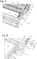
Fig. 5 shows a detail of the battery pack offigure 4 on an enlarged scale, -
Fig. 6 shows a bracket with integral cooling channel according to the disclosure, shown infigure 4 , -
Fig. 7 shows an interconnection member and front frame bracket attached to a bracket according to the disclosure, -
Fig. 8 shows a perspective side view of a detail on an enlarged scale of the interconnection member and bracket offigure 7 , -
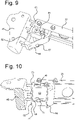
Fig. 9 shows a top view of the interconnection member and bracket offigure 7 , and -
Fig. 10 shows a vertical cross-sectional view through the brackets offigure 7 . -
Figure 1 shows aframe 1 of an electric vehicle comprising afront frame structure 2, arear frame structure 3, including a rear floor, and astructural battery assembly 4 forming abottom structure 5. Thestructural battery assembly 4 compriseslongitudinal side profiles rear frame structures battery pack 9 of interconnected battery modules.Cross beams top plate 10 of thebattery pack 9 and extend in a transverse direction, interconnecting theside profiles -
Figure 2 shows fourinterconnected battery modules cooling plate plate cooling channels longitudinal sides - Interconnecting
members longitudinal sides hollow center profile 37 is on each side adhesively connected to twomodules -
Figure 3 shows a top view of thebattery pack 9 offigure 1 , with thetop plate 10 removed. Thelongitudinal side profiles transverse beam 40. The interconnectingmembers brackets inner surface 42 the fronttransverse beam 40. Thefront frame structure 2 is attached viabrackets outside surface 47 of the fronttransverse beam 40 for connection to thefront frame structure 2. Via acoolant inlet nozzle 44, situated in a central area of the fronttransverse beam 40 between thebrackets cooling channels -
Figure 4 shows thebattery pack 9 with the coolingplates transverse beam 50 to which the interconnectingmembers center profile 37 are connected. An outlet manifold for the coolant is proved at the rear transverse beam 50.The individual battery cells of the modules 15-18 are shown. It can be seen that twocoolant inlets 52, 53 are provided, extending through the fronttransverse beam 40, and extend via a branching duct in a transverse direction to connect to coolingfluid inlets outer modules -
Figures 5 and 6 show an enlarged view of thecoolant duct 54 extending between atransverse end plate 60 of thebattery module 16 and theinner surface 42 of the fronttransverse beam 40. Theduct 54 branches off from theinlet 52 and extends to thebracket 43, and through thebracket 43 viachannel 57 to thecoolant inlet 55 of themodule 15, from which the battery cells have been omitted from the drawing. Theinlet 55 of themodule 15 in this embodiment is situated between thetransverse end plate 59 and theinner surface 42 of the fronttransverse beam 40 and is connected to cooling channels in abottom cooling plate 58, that may be used in combination with, or as an alternative to thetop cooling plates -
Figure 7 shows a force F that is passed on from thefront frame structure 2 via thebracket 46 to thebracket 48 and from there on in the longitudinal direction to the interconnectingmember 36. The moment M is taken up by thebracket 48. The fronttransverse beam 40 has been omitted from the drawing. -
Figure 8 shows apassage 68 provided in the interconnectingstructure 36 for thecoolant duct 67. -
Figure 9 shows the side faces 62,63 of thebracket 48 being connected via the front transverse beam 40 (not shown) to thebracket 45 of thefront frame structure 2 and to the interconnectingmember 35, respectively. The slantingface 64 of thebracket 48 faces theinlet 56 and to which thecoolant duct 67 connects. -
Figure 10 shows ashear plane 69 of thebracket 48, defining thecoolant duct 67 and extending between thetop plane 70 andbottom plane 71 of thebracket 48, interconnectingside face 62 and slantingface 64.
Claims (6)
- Battery assembly (9) for an electric vehicle comprising two spaced-apart longitudinal profiles (6,7) extending in a length direction L, interconnected to a front and a rear transverse beam (40,50), at least three beam shaped battery modules (15-18), interconnected along their longitudinal sides (26-29) via a plate-shaped interconnecting member (35,36), the interconnecting members (35,36) extending in the length direction and being attached to an inner surface (42) of the front transverse beam (40) via a bracket (43,48),
each battery module (15-18) comprising cooling channels (23,24) extending it the length direction L and having an inlet (55,56) situated between a transverse end face (59,60) of the module and the inner surface (42) of the front transverse beam (40),
a coolant inlet duct (52,53) extending from an external side the front transverse beam (40) in a central area situated between the brackets (43,48), for connecting to a coolant inlet of the central battery module (16,17),
connecting areas on the external side of the front transverse beam (40) for attaching to a front frame part (2,45,46) being situated adjacent to the central area, opposite the brackets (43,48), and
a branching duct (54) extending between a front transverse side (60) of the central module (16,17) to an inlet (55,56) that is situated between the transverse end face (59) of the side modules (15,18) and the front transverse beam (40) via a channel (57,67) through the bracket (43,48). - Battery assembly (9) according to claim 1, wherein the channel (57,67) is integrally formed in the material of the bracket (43,48) by casting or machining.
- Battery assembly (9) according to claim 1 or 2, wherein the bracket (43,48) is of substantially triangular cross-section with two rectangular side faces (62,63) adjacent the interconnecting member (35,36) and the front transverse beam (40) and a slanting face (64), comprising an upper and a lower transverse surface (70,71), the channel extending (57,67) in a transverse plane (69) attached to the side faces (62,63) and the slanting face (64) situated between the upper and lower transverse surface (70,71).
- Battery assembly (9) according to claim 3, the bracket (43,48) in the side face (62) adjacent the transverse beam (40) being provided with connecting passages for receiving connector pins of the front frame part (2), extending through the front transverse beam (40).
- Battery assembly (9) according to claim 4, wherein the interconnecting member (35,36) is at its front end provided with a pass-through opening (68) for the coolant channel (67), and attached via connector members extending through the interconnecting member (35,36), through passages in the side face (63) the bracket (48) facing the interconnecting member (35,36).
- Electric vehicle comprising a battery assembly (9) according to any of the preceding claims.
Priority Applications (3)
| Application Number | Priority Date | Filing Date | Title |
|---|---|---|---|
| EP21186238.8A EP4120439B1 (en) | 2021-07-16 | 2021-07-16 | Structural battery comprising cooling channels |
| US17/861,656 US20230017474A1 (en) | 2021-07-16 | 2022-07-11 | Structural Battery Comprising Cooling Channels |
| CN202210831339.0A CN115621602A (en) | 2021-07-16 | 2022-07-14 | Structural battery including cooling channels |
Applications Claiming Priority (1)
| Application Number | Priority Date | Filing Date | Title |
|---|---|---|---|
| EP21186238.8A EP4120439B1 (en) | 2021-07-16 | 2021-07-16 | Structural battery comprising cooling channels |
Publications (2)
| Publication Number | Publication Date |
|---|---|
| EP4120439A1 true EP4120439A1 (en) | 2023-01-18 |
| EP4120439B1 EP4120439B1 (en) | 2024-12-11 |
Family
ID=77226584
Family Applications (1)
| Application Number | Title | Priority Date | Filing Date |
|---|---|---|---|
| EP21186238.8A Active EP4120439B1 (en) | 2021-07-16 | 2021-07-16 | Structural battery comprising cooling channels |
Country Status (3)
| Country | Link |
|---|---|
| US (1) | US20230017474A1 (en) |
| EP (1) | EP4120439B1 (en) |
| CN (1) | CN115621602A (en) |
Families Citing this family (2)
| Publication number | Priority date | Publication date | Assignee | Title |
|---|---|---|---|---|
| USD1012853S1 (en) * | 2020-03-24 | 2024-01-30 | Acer Incorporated | Battery holder |
| US20230420787A1 (en) * | 2022-06-24 | 2023-12-28 | Rivian Ip Holdings, Llc | Battery pack bracket integration |
Citations (4)
| Publication number | Priority date | Publication date | Assignee | Title |
|---|---|---|---|---|
| US9937781B1 (en) * | 2016-12-19 | 2018-04-10 | GM Global Technology Operations LLC | Battery pack mounting architecture with shear plate for electric drive motor vehicles |
| CN109515216A (en) * | 2018-12-06 | 2019-03-26 | 中国第汽车股份有限公司 | Power battery of pure electric automobile assembly structure |
| US20210028422A1 (en) * | 2019-07-24 | 2021-01-28 | Hyundai Motor Company | Apparatus for cooling vehicle battery and fabrication method thereof |
| US20210175572A1 (en) * | 2019-01-09 | 2021-06-10 | Byd Company Limited | Battery pack, vehicle and energy storage device |
Family Cites Families (6)
| Publication number | Priority date | Publication date | Assignee | Title |
|---|---|---|---|---|
| US9819062B2 (en) * | 2014-11-14 | 2017-11-14 | Ford Global Technologies, Llc | Traction battery assembly with thermal device |
| US9533600B1 (en) * | 2015-09-03 | 2017-01-03 | GM Global Technology Operations LLC | Structurally integrated propulsion battery |
| JP6724061B2 (en) * | 2018-04-18 | 2020-07-15 | 本田技研工業株式会社 | Battery pack |
| US10559795B1 (en) * | 2018-12-19 | 2020-02-11 | Ford Global Technologies, Llc | Chassis brace for protecting traction battery |
| KR102673165B1 (en) * | 2019-11-14 | 2024-06-10 | 현대자동차주식회사 | Downward Movement Space Type 2attery Pack Mounting Module |
| CN111934052A (en) * | 2020-08-12 | 2020-11-13 | 领航博创新能源电池技术研究院(北京)有限公司 | Liquid cooling laminate polymer battery module, battery system and electric vehicle |
-
2021
- 2021-07-16 EP EP21186238.8A patent/EP4120439B1/en active Active
-
2022
- 2022-07-11 US US17/861,656 patent/US20230017474A1/en active Pending
- 2022-07-14 CN CN202210831339.0A patent/CN115621602A/en active Pending
Patent Citations (4)
| Publication number | Priority date | Publication date | Assignee | Title |
|---|---|---|---|---|
| US9937781B1 (en) * | 2016-12-19 | 2018-04-10 | GM Global Technology Operations LLC | Battery pack mounting architecture with shear plate for electric drive motor vehicles |
| CN109515216A (en) * | 2018-12-06 | 2019-03-26 | 中国第汽车股份有限公司 | Power battery of pure electric automobile assembly structure |
| US20210175572A1 (en) * | 2019-01-09 | 2021-06-10 | Byd Company Limited | Battery pack, vehicle and energy storage device |
| US20210028422A1 (en) * | 2019-07-24 | 2021-01-28 | Hyundai Motor Company | Apparatus for cooling vehicle battery and fabrication method thereof |
Also Published As
| Publication number | Publication date |
|---|---|
| EP4120439B1 (en) | 2024-12-11 |
| CN115621602A (en) | 2023-01-17 |
| US20230017474A1 (en) | 2023-01-19 |
Similar Documents
| Publication | Publication Date | Title |
|---|---|---|
| JP5372128B2 (en) | Side impact energy absorption and dispersion system using battery pack | |
| EP3619491B1 (en) | Support structure | |
| US20230017474A1 (en) | Structural Battery Comprising Cooling Channels | |
| US9419263B2 (en) | Battery pack | |
| KR102772122B1 (en) | The undercarriage of a car | |
| US8052206B2 (en) | Floorboard assembly for vehicle | |
| CN211764881U (en) | Vehicle battery module | |
| CN117546350A (en) | Drive battery for a motor vehicle and motor vehicle having such a drive battery | |
| CN111834568B (en) | Floor protection device with integrated cooling device, battery housing, battery and motor vehicle | |
| CN114552105B (en) | Battery pack for mounting on vehicle | |
| US12304295B2 (en) | Energy store floor assembly | |
| CN113795397A (en) | Motor vehicle with motor vehicle body and energy storage unit assembly | |
| CN113840749A (en) | Motor vehicle comprising an electric drive and a battery cell assembly integrated in the vehicle body | |
| CN118843553A (en) | Arrangement of an electric energy store on a body housing of a passenger vehicle | |
| CN115621652A (en) | Structural battery with reduced sill height | |
| CN116278697A (en) | Battery device for supplying energy to a traction drive of a partially electrically operated vehicle | |
| US11872899B2 (en) | Traction battery system for a motor vehicle and motor vehicle having an electric drive | |
| CN117098681A (en) | Vehicle structure integrated with battery module and cooling plate | |
| US20230261304A1 (en) | Structural battery pack cell signal and conversion pass-through | |
| US12358359B2 (en) | Structural battery for an electric vehicle | |
| CN113767027A (en) | Battery with control unit integrated in structural beam | |
| US20230026490A1 (en) | Structural Battery for an Electric Vehicle | |
| CN220483099U (en) | Battery pack upper cover, battery pack system and automobile | |
| CN220492045U (en) | Battery pack and vehicle | |
| CN112787015A (en) | Battery structure with energy absorbing member |
Legal Events
| Date | Code | Title | Description |
|---|---|---|---|
| PUAI | Public reference made under article 153(3) epc to a published international application that has entered the european phase |
Free format text: ORIGINAL CODE: 0009012 |
|
| STAA | Information on the status of an ep patent application or granted ep patent |
Free format text: STATUS: THE APPLICATION HAS BEEN PUBLISHED |
|
| AK | Designated contracting states |
Kind code of ref document: A1 Designated state(s): AL AT BE BG CH CY CZ DE DK EE ES FI FR GB GR HR HU IE IS IT LI LT LU LV MC MK MT NL NO PL PT RO RS SE SI SK SM TR |
|
| STAA | Information on the status of an ep patent application or granted ep patent |
Free format text: STATUS: REQUEST FOR EXAMINATION WAS MADE |
|
| 17P | Request for examination filed |
Effective date: 20230314 |
|
| RBV | Designated contracting states (corrected) |
Designated state(s): AL AT BE BG CH CY CZ DE DK EE ES FI FR GB GR HR HU IE IS IT LI LT LU LV MC MK MT NL NO PL PT RO RS SE SI SK SM TR |
|
| GRAP | Despatch of communication of intention to grant a patent |
Free format text: ORIGINAL CODE: EPIDOSNIGR1 |
|
| STAA | Information on the status of an ep patent application or granted ep patent |
Free format text: STATUS: GRANT OF PATENT IS INTENDED |
|
| INTG | Intention to grant announced |
Effective date: 20240808 |
|
| GRAS | Grant fee paid |
Free format text: ORIGINAL CODE: EPIDOSNIGR3 |
|
| GRAA | (expected) grant |
Free format text: ORIGINAL CODE: 0009210 |
|
| STAA | Information on the status of an ep patent application or granted ep patent |
Free format text: STATUS: THE PATENT HAS BEEN GRANTED |
|
| AK | Designated contracting states |
Kind code of ref document: B1 Designated state(s): AL AT BE BG CH CY CZ DE DK EE ES FI FR GB GR HR HU IE IS IT LI LT LU LV MC MK MT NL NO PL PT RO RS SE SI SK SM TR |
|
| REG | Reference to a national code |
Ref country code: GB Ref legal event code: FG4D |
|
| REG | Reference to a national code |
Ref country code: CH Ref legal event code: EP |
|
| P01 | Opt-out of the competence of the unified patent court (upc) registered |
Free format text: CASE NUMBER: APP_62641/2024 Effective date: 20241125 |
|
| REG | Reference to a national code |
Ref country code: IE Ref legal event code: FG4D |
|
| REG | Reference to a national code |
Ref country code: DE Ref legal event code: R096 Ref document number: 602021023154 Country of ref document: DE |
|
| REG | Reference to a national code |
Ref country code: LT Ref legal event code: MG9D |
|
| PG25 | Lapsed in a contracting state [announced via postgrant information from national office to epo] |
Ref country code: HR Free format text: LAPSE BECAUSE OF FAILURE TO SUBMIT A TRANSLATION OF THE DESCRIPTION OR TO PAY THE FEE WITHIN THE PRESCRIBED TIME-LIMIT Effective date: 20241211 |
|
| PG25 | Lapsed in a contracting state [announced via postgrant information from national office to epo] |
Ref country code: FI Free format text: LAPSE BECAUSE OF FAILURE TO SUBMIT A TRANSLATION OF THE DESCRIPTION OR TO PAY THE FEE WITHIN THE PRESCRIBED TIME-LIMIT Effective date: 20241211 |
|
| PG25 | Lapsed in a contracting state [announced via postgrant information from national office to epo] |
Ref country code: BG Free format text: LAPSE BECAUSE OF FAILURE TO SUBMIT A TRANSLATION OF THE DESCRIPTION OR TO PAY THE FEE WITHIN THE PRESCRIBED TIME-LIMIT Effective date: 20241211 |
|
| REG | Reference to a national code |
Ref country code: NL Ref legal event code: MP Effective date: 20241211 |
|
| PG25 | Lapsed in a contracting state [announced via postgrant information from national office to epo] |
Ref country code: ES Free format text: LAPSE BECAUSE OF FAILURE TO SUBMIT A TRANSLATION OF THE DESCRIPTION OR TO PAY THE FEE WITHIN THE PRESCRIBED TIME-LIMIT Effective date: 20241211 |
|
| PG25 | Lapsed in a contracting state [announced via postgrant information from national office to epo] |
Ref country code: NO Free format text: LAPSE BECAUSE OF FAILURE TO SUBMIT A TRANSLATION OF THE DESCRIPTION OR TO PAY THE FEE WITHIN THE PRESCRIBED TIME-LIMIT Effective date: 20250311 |
|
| PG25 | Lapsed in a contracting state [announced via postgrant information from national office to epo] |
Ref country code: GR Free format text: LAPSE BECAUSE OF FAILURE TO SUBMIT A TRANSLATION OF THE DESCRIPTION OR TO PAY THE FEE WITHIN THE PRESCRIBED TIME-LIMIT Effective date: 20250312 Ref country code: LV Free format text: LAPSE BECAUSE OF FAILURE TO SUBMIT A TRANSLATION OF THE DESCRIPTION OR TO PAY THE FEE WITHIN THE PRESCRIBED TIME-LIMIT Effective date: 20241211 |
|
| PG25 | Lapsed in a contracting state [announced via postgrant information from national office to epo] |
Ref country code: RS Free format text: LAPSE BECAUSE OF FAILURE TO SUBMIT A TRANSLATION OF THE DESCRIPTION OR TO PAY THE FEE WITHIN THE PRESCRIBED TIME-LIMIT Effective date: 20250311 |
|
| PG25 | Lapsed in a contracting state [announced via postgrant information from national office to epo] |
Ref country code: NL Free format text: LAPSE BECAUSE OF FAILURE TO SUBMIT A TRANSLATION OF THE DESCRIPTION OR TO PAY THE FEE WITHIN THE PRESCRIBED TIME-LIMIT Effective date: 20241211 |
|
| REG | Reference to a national code |
Ref country code: AT Ref legal event code: MK05 Ref document number: 1751112 Country of ref document: AT Kind code of ref document: T Effective date: 20241211 |
|
| PG25 | Lapsed in a contracting state [announced via postgrant information from national office to epo] |
Ref country code: SM Free format text: LAPSE BECAUSE OF FAILURE TO SUBMIT A TRANSLATION OF THE DESCRIPTION OR TO PAY THE FEE WITHIN THE PRESCRIBED TIME-LIMIT Effective date: 20241211 |
|
| PG25 | Lapsed in a contracting state [announced via postgrant information from national office to epo] |
Ref country code: PL Free format text: LAPSE BECAUSE OF FAILURE TO SUBMIT A TRANSLATION OF THE DESCRIPTION OR TO PAY THE FEE WITHIN THE PRESCRIBED TIME-LIMIT Effective date: 20241211 |
|
| PGFP | Annual fee paid to national office [announced via postgrant information from national office to epo] |
Ref country code: GB Payment date: 20250619 Year of fee payment: 5 |