EP4120310B1 - Real time monitoring and parametric modifications for electronic circuit breakers through a remote device - Google Patents
Real time monitoring and parametric modifications for electronic circuit breakers through a remote device Download PDFInfo
- Publication number
- EP4120310B1 EP4120310B1 EP22183928.5A EP22183928A EP4120310B1 EP 4120310 B1 EP4120310 B1 EP 4120310B1 EP 22183928 A EP22183928 A EP 22183928A EP 4120310 B1 EP4120310 B1 EP 4120310B1
- Authority
- EP
- European Patent Office
- Prior art keywords
- breaker
- electronic circuit
- circuit breaker
- mobile app
- app
- Prior art date
- Legal status (The legal status is an assumption and is not a legal conclusion. Google has not performed a legal analysis and makes no representation as to the accuracy of the status listed.)
- Active
Links
Images





Classifications
-
- H—ELECTRICITY
- H01—ELECTRIC ELEMENTS
- H01H—ELECTRIC SWITCHES; RELAYS; SELECTORS; EMERGENCY PROTECTIVE DEVICES
- H01H71/00—Details of the protective switches or relays covered by groups H01H73/00 - H01H83/00
- H01H71/10—Operating or release mechanisms
- H01H71/12—Automatic release mechanisms with or without manual release
- H01H71/123—Automatic release mechanisms with or without manual release using a solid-state trip unit
-
- H—ELECTRICITY
- H01—ELECTRIC ELEMENTS
- H01H—ELECTRIC SWITCHES; RELAYS; SELECTORS; EMERGENCY PROTECTIVE DEVICES
- H01H9/00—Details of switching devices, not covered by groups H01H1/00 - H01H7/00
- H01H9/16—Indicators for switching condition, e.g. "on" or "off"
- H01H9/167—Circuits for remote indication
-
- G—PHYSICS
- G08—SIGNALLING
- G08C—TRANSMISSION SYSTEMS FOR MEASURED VALUES, CONTROL OR SIMILAR SIGNALS
- G08C17/00—Arrangements for transmitting signals characterised by the use of a wireless electrical link
- G08C17/02—Arrangements for transmitting signals characterised by the use of a wireless electrical link using a radio link
-
- H—ELECTRICITY
- H01—ELECTRIC ELEMENTS
- H01H—ELECTRIC SWITCHES; RELAYS; SELECTORS; EMERGENCY PROTECTIVE DEVICES
- H01H71/00—Details of the protective switches or relays covered by groups H01H73/00 - H01H83/00
- H01H71/04—Means for indicating condition of the switching device
-
- H—ELECTRICITY
- H01—ELECTRIC ELEMENTS
- H01H—ELECTRIC SWITCHES; RELAYS; SELECTORS; EMERGENCY PROTECTIVE DEVICES
- H01H71/00—Details of the protective switches or relays covered by groups H01H73/00 - H01H83/00
- H01H71/74—Means for adjusting the conditions under which the device will function to provide protection
-
- H—ELECTRICITY
- H02—GENERATION; CONVERSION OR DISTRIBUTION OF ELECTRIC POWER
- H02H—EMERGENCY PROTECTIVE CIRCUIT ARRANGEMENTS
- H02H3/00—Emergency protective circuit arrangements for automatic disconnection directly responsive to an undesired change from normal electric working condition with or without subsequent reconnection ; integrated protection
- H02H3/006—Calibration or setting of parameters
-
- H—ELECTRICITY
- H01—ELECTRIC ELEMENTS
- H01H—ELECTRIC SWITCHES; RELAYS; SELECTORS; EMERGENCY PROTECTIVE DEVICES
- H01H9/00—Details of switching devices, not covered by groups H01H1/00 - H01H7/00
- H01H9/16—Indicators for switching condition, e.g. "on" or "off"
- H01H9/168—Indicators for switching condition, e.g. "on" or "off" making use of an electromagnetic wave communication
-
- H—ELECTRICITY
- H02—GENERATION; CONVERSION OR DISTRIBUTION OF ELECTRIC POWER
- H02H—EMERGENCY PROTECTIVE CIRCUIT ARRANGEMENTS
- H02H1/00—Details of emergency protective circuit arrangements
- H02H1/0038—Details of emergency protective circuit arrangements concerning the connection of the detecting means, e.g. for reducing their number
- H02H1/0053—Means for storing the measured quantities during a predetermined time
-
- H—ELECTRICITY
- H02—GENERATION; CONVERSION OR DISTRIBUTION OF ELECTRIC POWER
- H02H—EMERGENCY PROTECTIVE CIRCUIT ARRANGEMENTS
- H02H1/00—Details of emergency protective circuit arrangements
- H02H1/0061—Details of emergency protective circuit arrangements concerning transmission of signals
Definitions
- aspects of the present invention generally relate to real time monitoring and parametric modifications for electronic circuit breakers through a remote device with a graphical interface.
- US 2014/170971 A1 describes an electrical distribution system wherein information is communicated to and/or from an electrical component of the electrical distribution system using near-field communications. The information may be communicated to and/or from the electrical component using an electronic device such as a dedicated near-field device, a smartphone or a configuration card device.
- US 2013/329331 A1 describes A circuit breaker (such as a miniature circuit breaker) that wirelessly communicates state and fault information to a main energy monitoring module.
- the wireless circuit breaker includes a transceiver and a power supply that harvests energy inductively from the line current conductor without the need for a connection to a neutral conductor.
- the present way to get insight into the unwanted tripping problem is to hook up oscilloscopes to an electronic circuit breaker while in the panel to retrieve more information.
- the circuit breaker is brought back to a R&D lab facility to retrieve information that was saved previously in the circuit breaker.
- a breaker algorithm After analyzing the load data in the R&D lab, one has to alter a breaker algorithm to treat these unusual loads as normal and safe. After this, new firmware code of the circuit breaker would have to get tested with a problematic electrical load to make sure the circuit breaker doesn't still trip on it.
- aspects of the present invention relate to an electronic circuit breaker for a residential application.
- Real time monitoring and parametric modifications for electronic circuit breakers through a remote device with a graphical interface is provided.
- the invention lets a user retrieve information from an electronic circuit breaker installed in the panel wirelessly to a mobile phone application (APP).
- the APP can show live current, voltage and RF signal data which are used in a breaker algorithm to trip in case of an unsafe and arcing electrical load.
- the APP working in tandem with the electronic circuit breaker can act like an oscilloscope where the user can set certain trigger conditions and the APP would show captured results.
- the APP can also share the retrieved data by means of email or messaging Apps outside of the mobile phone.
- the R&D experts can now look at the waveforms of the problematic electrical load very quick and recommend fixes in the breaker algorithm.
- the APP can also allow the user to tweak some of the breaker thresholds to alter the breaker algorithm. Alternately, if there is a code update that is necessary to fix the issue then a new firmware code can be programmed into the electronic circuit breaker wirelessly through the APP. The electronic circuit breaker can then be tested with the problematic electrical load to make sure the new firmware code has helped fix the unwanted tripping problem.
- This invention speeds up troubleshooting time significantly and saves on costs involved in making expensive field visits from R&D staff or shipping expensive equipment around the country for troubleshooting visits.
- the new breaker algorithm also can store previous trip events with a time stamp. This information can be retrieved on power up to find how many days power has been down on that breaker.
- a system comprising an electronic circuit breaker and a mobile application (APP) running on a remote device with a graphical user interface
- the electronic circuit breaker comprises a transceiver to wirelessly transmit information including waveform data and a microcontroller including a processor and a memory.
- the breaker further comprises computer-readable firmware code stored in the memory which, when executed by the processor, causes the microcontroller to: monitor in real-time one or more breaker functional parameters to determine parametric modifications, wirelessly transmit the information that was saved previously in the electronic circuit breaker about the one or more breaker functional parameters to a remote device with a graphical user interface, alter a breaker algorithm after analyzing load data of problematic electrical loads in a mobile application (APP) of the remote device to treat the problematic electrical loads as normal and safe and test the computer-readable firmware code with a problematic electrical load to make sure the electronic circuit breaker doesn't still trip on the problematic electrical load.
- APP mobile application
- a method of retrieving waveform data from an electronic circuit breaker wirelessly and altering a breaker code wirelessly comprises providing a transceiver to wirelessly transmit information including waveform data, providing a microcontroller including a processor and a memory, providing computer-readable firmware code stored in the memory which, when executed by the processor, causes the microcontroller to: monitor in real-time one or more breaker functional parameters to determine parametric modifications, wirelessly transmit the information that was saved previously in the electronic circuit breaker about the one or more breaker functional parameters to a remote device with a graphical user interface, alter a breaker algorithm after analysis of load data of problematic electrical loads in a mobile application (APP) of the remote device to treat the problematic electrical loads as normal and safe and test the computer-readable firmware code with a problematic electrical load to make sure the electronic circuit breaker doesn't still trip on the problematic electrical load.
- APP mobile application
- the invention provides ability to retrieve waveform data from a breaker wirelessly or have ability to alter the breaker code wirelessly.
- the invention here reduces troubleshooting time and costs significantly by incorporating an oscilloscope feature within an electronic circuit breaker itself and adding the feature to wirelessly retrieve information from a mobile phone.
- the ability to update code on the electronic circuit breaker wirelessly speeds up time in verifying new code against the problematic electrical load. Also, giving the user information on how long the electronic circuit breaker was down is useful information.
- Embodiments of the present invention are not limited to use in the described devices or methods.
- FIGs. 1-21 These and other embodiments of the electronic circuit breaker according to the present disclosure are described below with reference to FIGs. 1-21 herein.
- Like reference numerals used in the drawings identify similar or identical elements throughout the several views. The drawings are not necessarily drawn to scale.
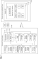
- FIG. 1 represents a block diagram of an electronic circuit breaker 105 that wirelessly communicates with a mobile application (APP) 107 for diagnostics purposes via a wireless link 103 in accordance with an exemplary embodiment of the present invention.
- the present invention generally relates to real time monitoring and parametric modifications for the electronic circuit breaker 105 through a remote device (e.g., a mobile phone) 109 with a graphical user interface 132.
- the electronic circuit breaker 105 comprises a transceiver 110 to wirelessly transmit information including waveform data 112.
- the electronic circuit breaker 105 further comprises a microcontroller 115 including a processor 117(1) and a memory 117(2).
- the electronic circuit breaker 105 further comprises computer-readable firmware code 120 stored in the memory 117(2) which, when executed by the processor 117(1), causes the microcontroller 115 to monitor in real-time one or more breaker functional parameters 122(1-n) to determine parametric modifications 125(1-n), wirelessly transmit information 127 that was saved previously in the electronic circuit breaker 105 about the one or more breaker functional parameters 122(1-n) to the remote device 109 with the graphical user interface 132, alter a breaker algorithm 135 after analyzing load data 137 of problematic electrical loads 140 in the mobile application (APP) 107 of the remote device 109 to treat the problematic electrical loads 140 as normal and safe and test the computer-readable firmware code 120 with a problematic electrical load 140(1) to make sure the electronic circuit breaker 105 doesn't still trip on the problematic electrical load 140(1).
- APP mobile application
- the computer-readable firmware code 120 lets the mobile application (APP) 107 wirelessly retrieve the information 127 from the electronic circuit breaker 105 installed in a panel.
- the mobile application (APP) 107 is configured to show live current 145(1), voltage 145(2) and Radio Frequency (RF) signal data (145(3) which are used in the breaker algorithm 135 to trip in case of an unsafe and arcing electrical load such as the problematic electrical load 140(1).
- the mobile application (APP) 107 is configured to work in tandem with the electronic circuit breaker 105 so it can act like an oscilloscope where a user can set certain trigger conditions 150(1-n) and the mobile application (APP) 107 will show captured results 152.
- the mobile application (APP) is configured to share any retrieved data 155 by means of email or messaging Apps outside of a mobile phone 109 on which the mobile application (APP) 107 is installed.
- waveforms 162 of the problematic electrical load 140(1) can be examined and fixes 165 in the breaker algorithm 135 recommended.
- the mobile application (APP) 107 enables a user to tweak one or more of breaker thresholds 167(1-m) to alter the breaker algorithm 135.
- a new code 170 can be programmed into the electronic circuit breaker 105 wirelessly through the mobile application (APP) 107.
- the electronic circuit breaker 105 can then be tested with the problematic electrical load 140(1) to ensure the new code 170 has helped fix a unwanted tripping problem 172.
- the breaker algorithm 135 is configured to store previous trip events 175 with a time stamp 177.
- Arc Fault Circuit Interrupter (AFCI) Diagnostics is a mobile App that is available both in Android and iOS platforms to communicate with the breakers to perform diagnostic troubleshooting.
- a mobile phone communicates with a breaker over Bluetooth Low Energy 5.0 protocol.
- the mobile App can be downloaded and installed using information from the manual document. Once the mobile App is installed, a user can follow a manual document to set up the breaker for troubleshooting and collecting data.
- the manual document identifies the features present in the mobile App. Also, the manual document assumes the communicating breaker is running a certain firmware version. Click on the mobile App icon from the mobile phone to see a splash screen followed by a screen showing the list of available breaker devices in the vicinity.
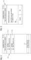
- FIG. 2 it illustrates a schematic of a user interface 205 of a mobile phone application (APP) that shows available devices 210(1-2) showing breakers in the vicinity in accordance with an exemplary embodiment of the present invention.
- the available devices screen is the first screen that a user will view after the mobile App is loaded. It will display any wireless breaker ("AFCIBLE") that is within range.
- Available Devices screen also has a view history button 215 that allows the user to view any previously saved records.
- FIG. 3 it illustrates a schematic of a display screen 305 of a mobile phone application (APP) that shows pairing of a mobile phone with an electronic circuit breaker in accordance with an exemplary embodiment of the present invention.
- APP mobile phone application
- the user can click on the device of interest from the displayed list. If this is the first time that the user is connecting their phone to a given breaker, they will have to enter the multi-digit passcode to pair the phone to the breaker.
- the user will be navigated to the Dashboard section of the mobile App, showing the breaker details. The user can also view additional information about the app from this page by clicking the "i" icon.
- FIG. 4 illustrates a schematic of offline records 405 stored in the mobile phone in accordance with an exemplary embodiment of the present invention.
- the user has the option to view, share and delete previously saved records (on the mobile phone), without having to connect to the breaker.
- FIG. 5 it illustrates a schematic of browsing through offline records 505 in accordance with an exemplary embodiment of the present invention. Click a "show” button 507 to view a record 510 or click a "share” button 512 to send the record 510 via email or messaging.
- FIG. 6 it illustrates a schematic of view after clicking show on the view history screen in accordance with an exemplary embodiment of the present invention.
- the display includes a graph for a load current 605, RF signal 607 and a line voltage 610. A trigger is also shown.
- FIG. 7 it illustrates a schematic of a dashboard screen in accordance with an exemplary embodiment of the present invention.
- the mobile App displays a dashboard page 705, upon a successful connection.
- the other pages like the status, record and settings page can be accessed by clicking on their respective icons on the bottom of the mobile App screen.
- the dashboard page 705 shows the Breaker Name (centered on the top), breaker rating, type, firmware revision and the date/time as set in the breaker device.
- Arc fault and overcurrent fault statuses are displayed in the form of LED bars 710(1-2) to represent how close the breaker is to trip on these faults.
- the breaker name and date/time fields can be edited from the settings page.
- FIG. 8 it illustrates a schematic of clicking "view all" soft button 805 to see a list of all alerts in accordance with an exemplary embodiment of the present invention.
- Alert notifications are displayed on this screen if any of the following conditions happen: i. if breaker is close to tripping on an arc fault, ii. if breaker is close to tripping on an overcurrent fault, iii. if the peak current or RMS current levels go beyond set threshold limits., iv. if breaker completed an oscilloscope capture and v. if phone lost connection with the breaker unexpectedly.
- FIG. 9 it illustrates a schematic of a list 905 of all alerts in accordance with an exemplary embodiment of the present invention.
- a list of all the alerts and notifications (maximum of 50) along with a time stamp can be viewed by clicking on the view all soft button next to the alert on the dashboard page or breaker status screen.
- the individual alert message can be deleted from the list by swiping the finger across the alert.
- FIG. 10 illustrates a schematic of a status screen 1005 in accordance with an exemplary embodiment of the present invention.
- the status screen 1005 shows more details of a circuit breaker like load current 1007 and RF signal data 1010 in the form of LED bars 1015(1-2). It also shows live peak 1020 and RMS 1025 current values.
- the status screen 1005 also has details of a trip state 1030 including the last time the breaker tripped, including the fault condition that led to the trip and the timestamp of that event.
- the alert/notification messages 1035 are also displayed on the status screen 1005.
- FIG. 11 illustrates a schematic of a record screen 1105 showing the 2 tabs in accordance with an exemplary embodiment of the present invention.
- the record screen 1105 has two tabs - new record 1107 and history 1110.
- the record screen 1105 provides an oscilloscope like interface to set up trigger conditions and to display the captured waveform while also giving the user the option to save all this data and view previously saved data.
- the new record 1107 tab lets the user configure a scope capture and view the associated data. This tab has two sections- settings and graph.
- FIG. 12 illustrates a schematic of a new record screen 1205 with trigger settings option in accordance with an exemplary embodiment of the present invention.
- Scope trigger settings 1207 are shown (expanded) by clicking on a down arrow to the right of settings (if it is not already expanded). After the trigger settings 1207 are selected, click on save settings 1210 to save these into the breaker's memory.
- Trigger Source 1212 Trigger Direction 1215
- Trigger Window 1217 Trigger Level 1220
- Buffer Size 1222 The following are the list of parameters to set up a scope capture: Trigger Source 1212, Trigger Direction 1215, Trigger Window 1217, Trigger Level 1220 and Buffer Size 1222.
- Trigger Source 1212 This determines the signal that would be used for the triggering the capture.
- the options for Trigger Source 1212 are:
- the Trigger Window 1217 defines the length of data captured before and after the trigger event. Range: 20 cycles before trigger - 10 cycles before and 10 cycles after trigger - 20 cycles after trigger
- the Trigger Level 1220 is the value in ADC bits at which the oscilloscope function should trigger (dependent upon the Trigger Direction 1215).
- the buffer size 1222 represents the size of the waveform captured in the breaker.
- FIG. 13 illustrates a schematic of a record screen1305 - how to set up a new capture in accordance with an exemplary embodiment of the present invention.
- FIG. 14 illustrates a schematic of waveform data showing graph in accordance with an exemplary embodiment of the present invention.
- the waveform data is displayed on the graph once the data has been downloaded.
- the waveform shows 3 signals that are plotted:
- the user can turn a signal on/off on graph 1415 by checking/unchecking the corresponding tick box 1420(1-3) below the graph 1415.
- the user can also zoom in and out of the graph by using finger pinching actions.
- the graph can be scrolled through using finger sliding action.
- FIG. 15 illustrates a schematic of saving waveform data in accordance with an exemplary embodiment of the present invention.
- a user can save the waveforms along with the trigger settings associated with the capture by clicking on a save button on top of the graph.
- the file name can accept alphabets, numbers, or characters like hyphen(-), underscore(_) and hash(#).
- click save 1507 to store the waveform file in the mobile App.
- the waveforms can be shared outside the mobile phone by clicking on a share button on top of the graph. This brings up the messaging or email Apps that can be used to message or email the waveform data.
- FIG. 16 illustrates a schematic of viewing list of saved records in accordance with an exemplary embodiment of the present invention.
- a history tab 1605 shows all the waveforms that were captured on the circuit breaker (using the mobile phone) and saved to the mobile phone. It displays a list 1607 of all the waveform records by the file name and time stamp.
- a delete all button 1610 at the bottom of the list deletes all the records related to the circuit breaker that were stored on the mobile phone. The user can view a record in detail by clicking on a down arrow button 1615 next to a filename 1620.
- FIG. 17 illustrates a schematic of viewing details from a saved record 1700 in accordance with an exemplary embodiment of the present invention.
- the record 1700 details include all trigger settings 1702 that were used for the capture.
- the user can press a show button 1705 to view the graph which provides a very similar user interface like the graph section of a new record tab 1710.
- the user can also share the waveform record via email or message from this screen by pressing a share button 1715 next to the show button 1705.
- the user can also delete a record from the phone by clicking a delete button 1720 next to the share button 1715.
- the mobile App has a settings page where the user can view and update the mobile App and breaker settings.
- the following settings can be updated: Breaker Time and Date, Breaker Name, Breaker Firmware (Application Coprocessor and Wireless Coprocessor), Variables, Notification Settings and Demo Mode.
- a screen allows the user to set the Time and Date of the breaker. This setting will be active in the breaker until it loses power. By default, the time and date on this screen will match the time that is set on the user's mobile phone.
- a screen allows the user to set the Breaker Name. It allows up to 25 alpha numeric characters. This setting will be permanently saved in the breaker when "Save Changes" is clicked.
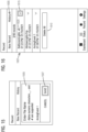
- FIG. 18 illustrates a schematic of starting firmware upgrade in accordance with an exemplary embodiment of the present invention.
- This screen 1805 allows the user to do a wireless firmware update to the circuit breaker 105. Updating the firmware include the following steps.
- FIG. 19 illustrates a schematic of editing variables in accordance with an exemplary embodiment of the present invention.
- a variables screen 1905 has five variables that are stored to Flash. After making changes to the variables, click a Save Variables button 1910 to permanently save these parameters to the circuit breaker 105.
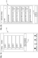
- FIG. 20 illustrates a schematic of editing threshold settings for alerts in accordance with an exemplary embodiment of the present invention.
- This screen 2005 allows the user to set thresholds for Faults and Current.
- the threshold values for the following alerts can be set here: Arc Fault (Range of 0-12), Overcurrent Fault (Range of 0-12), Minimum/ Maximum Peak Current, Minimum/ Maximum RMS Current and Maximum number of waveform records that can be saved per breaker.
- Peak current and RMS current related alerts can be enabled or disabled by using the Activate switch.
- the user needs to press a save button 2010 for the settings to be stored in the mobile App database for each breaker device.
- alerts When the parameters go beyond the threshold values listed here, alerts would be generated on the Dashboard and Status page.
- the related alert would be displayed when the user attempts to start a new scope capture on the Record screen. In that scenario, the user would have to delete at least one record before starting the new capture.
- Demo Mode option allows the user that is connected to a breaker device to get sample data on the Dashboard and Status pages. This option is primarily used by developers and is for demonstration purpose only.
- FIG. 21 illustrates a schematic view of a flow chart of a method 2100 of retrieving waveform data from an electronic circuit breaker wirelessly and altering a breaker code wirelessly in accordance with an exemplary embodiment of the present invention.
- the method 2100 comprises a step 2105 of providing a transceiver to wirelessly transmit information including waveform data.
- the method 2100 further comprises a step 2110 of providing a microcontroller including a processor and a memory.
- the method 2100 further comprises a step 2115 of providing computer-readable firmware code stored in the memory which, when executed by the processor, causes the microcontroller to: monitor in real-time one or more breaker functional parameters to determine parametric modifications, wirelessly transmit the information that was saved previously in the electronic circuit breaker about the one or more breaker functional parameters to a remote device with a graphical user interface, alter a breaker algorithm after analyzing load data of problematic electrical loads in a mobile application (APP) of the remote device to treat the problematic electrical loads as normal and safe and test the computer-readable firmware code with a problematic electrical load to make sure the electronic circuit breaker doesn't still trip on the problematic electrical load.
- APP mobile application
- the techniques described herein can be particularly useful for AFCI diagnostics via a mobile App. While particular embodiments are described in terms of these AFCI diagnostics, the techniques described herein are not limited to such a set-up but can also be used with other diagnostics.
- any examples or illustrations given herein are not to be regarded in any way as restrictions on, limits to, or express definitions of, any term or terms with which they are utilized. Instead, these examples or illustrations are to be regarded as being described with respect to one particular embodiment and as illustrative only. Those of ordinary skill in the art will appreciate that any term or terms with which these examples or illustrations are utilized will encompass other embodiments which may or may not be given therewith or elsewhere in the specification and all such embodiments are intended to be included within the scope of that term or terms.
Landscapes
- Physics & Mathematics (AREA)
- Engineering & Computer Science (AREA)
- Computer Networks & Wireless Communication (AREA)
- General Physics & Mathematics (AREA)
- Electromagnetism (AREA)
- Breakers (AREA)
Description
- Aspects of the present invention generally relate to real time monitoring and parametric modifications for electronic circuit breakers through a remote device with a graphical interface.
-
US 2014/170971 A1 describes an electrical distribution system wherein information is communicated to and/or from an electrical component of the electrical distribution system using near-field communications. The information may be communicated to and/or from the electrical component using an electronic device such as a dedicated near-field device, a smartphone or a configuration card device.
US 2013/329331 A1 describes A circuit breaker (such as a miniature circuit breaker) that wirelessly communicates state and fault information to a main energy monitoring module. The wireless circuit breaker includes a transceiver and a power supply that harvests energy inductively from the line current conductor without the need for a connection to a neutral conductor. - Currently, there is no easy way to understand why a residential circuit breaker trips on electrical loads that seem completely safe and normal. Also troubleshooting problems associated with these unwanted trips are time consuming and expensive to the business.
- The present way to get insight into the unwanted tripping problem is to hook up oscilloscopes to an electronic circuit breaker while in the panel to retrieve more information. Alternately, the circuit breaker is brought back to a R&D lab facility to retrieve information that was saved previously in the circuit breaker. After analyzing the load data in the R&D lab, one has to alter a breaker algorithm to treat these unusual loads as normal and safe. After this, new firmware code of the circuit breaker would have to get tested with a problematic electrical load to make sure the circuit breaker doesn't still trip on it.
- Therefore, there is a need for a better electronic circuit breaker for a residential application.
- Briefly described, aspects of the present invention relate to an electronic circuit breaker for a residential application. Real time monitoring and parametric modifications for electronic circuit breakers through a remote device with a graphical interface is provided. The invention lets a user retrieve information from an electronic circuit breaker installed in the panel wirelessly to a mobile phone application (APP). The APP can show live current, voltage and RF signal data which are used in a breaker algorithm to trip in case of an unsafe and arcing electrical load. The APP working in tandem with the electronic circuit breaker can act like an oscilloscope where the user can set certain trigger conditions and the APP would show captured results. The APP can also share the retrieved data by means of email or messaging Apps outside of the mobile phone. The R&D experts can now look at the waveforms of the problematic electrical load very quick and recommend fixes in the breaker algorithm. The APP can also allow the user to tweak some of the breaker thresholds to alter the breaker algorithm. Alternately, if there is a code update that is necessary to fix the issue then a new firmware code can be programmed into the electronic circuit breaker wirelessly through the APP. The electronic circuit breaker can then be tested with the problematic electrical load to make sure the new firmware code has helped fix the unwanted tripping problem. This invention speeds up troubleshooting time significantly and saves on costs involved in making expensive field visits from R&D staff or shipping expensive equipment around the country for troubleshooting visits. The new breaker algorithm also can store previous trip events with a time stamp. This information can be retrieved on power up to find how many days power has been down on that breaker.
- In accordance with one illustrative embodiment of the present invention, a system comprising an electronic circuit breaker and a mobile application (APP) running on a remote device with a graphical user interface, the electronic circuit breaker comprises a transceiver to wirelessly transmit information including waveform data and a microcontroller including a processor and a memory. The breaker further comprises computer-readable firmware code stored in the memory which, when executed by the processor, causes the microcontroller to: monitor in real-time one or more breaker functional parameters to determine parametric modifications, wirelessly transmit the information that was saved previously in the electronic circuit breaker about the one or more breaker functional parameters to a remote device with a graphical user interface, alter a breaker algorithm after analyzing load data of problematic electrical loads in a mobile application (APP) of the remote device to treat the problematic electrical loads as normal and safe and test the computer-readable firmware code with a problematic electrical load to make sure the electronic circuit breaker doesn't still trip on the problematic electrical load.
- In accordance with one illustrative embodiment of the present invention, a method of retrieving waveform data from an electronic circuit breaker wirelessly and altering a breaker code wirelessly is provided. The method comprises providing a transceiver to wirelessly transmit information including waveform data, providing a microcontroller including a processor and a memory, providing computer-readable firmware code stored in the memory which, when executed by the processor, causes the microcontroller to: monitor in real-time one or more breaker functional parameters to determine parametric modifications, wirelessly transmit the information that was saved previously in the electronic circuit breaker about the one or more breaker functional parameters to a remote device with a graphical user interface, alter a breaker algorithm after analysis of load data of problematic electrical loads in a mobile application (APP) of the remote device to treat the problematic electrical loads as normal and safe and test the computer-readable firmware code with a problematic electrical load to make sure the electronic circuit breaker doesn't still trip on the problematic electrical load.
-
-
FIG. 1 illustrates a schematic of a block diagram of an electronic circuit breaker that wirelessly communicates with a mobile phone application (APP) for diagnostics purposes in accordance with an exemplary embodiment of the present invention. -
FIG. 2 illustrates a schematic of a user interface of a mobile phone application (APP) that shows available devices showing breakers in the vicinity in accordance with an exemplary embodiment of the present invention. -
FIG. 3 illustrates a schematic of a display screen of a mobile phone application (APP) that shows pairing of a mobile phone with an electronic circuit breaker in accordance with an exemplary embodiment of the present invention. -
FIG. 4 illustrates a schematic of offline records stored in the mobile phone in accordance with an exemplary embodiment of the present invention. -
FIG. 5 illustrates a schematic of browsing through offline records in accordance with an exemplary embodiment of the present invention. -
FIG. 6 illustrates a schematic of view after clicking show on the view history screen in accordance with an exemplary embodiment of the present invention. -
FIG. 7 illustrates a schematic of a dashboard screen in accordance with an exemplary embodiment of the present invention. -
FIG. 8 illustrates a schematic of clicking "View All" to see a list of all alerts in accordance with an exemplary embodiment of the present invention. -
FIG. 9 illustrates a schematic of a list of all alerts in accordance with an exemplary embodiment of the present invention. -
FIG. 10 illustrates a schematic of a status screen in accordance with an exemplary embodiment of the present invention. -
FIG. 11 illustrates a schematic of a record screen showing the 2 tabs in accordance with an exemplary embodiment of the present invention. -
FIG. 12 illustrates a schematic of a new record screen with trigger settings option in accordance with an exemplary embodiment of the present invention. -
FIG. 13 illustrates a schematic of a record screen- how to set up a new capture in accordance with an exemplary embodiment of the present invention. -
FIG. 14 illustrates a schematic of waveform data showing graph in accordance with an exemplary embodiment of the present invention. -
FIG. 15 illustrates a schematic of saving waveform data in accordance with an exemplary embodiment of the present invention. -
FIG. 16 illustrates a schematic of viewing list of saved records in accordance with an exemplary embodiment of the present invention. -
FIG. 17 illustrates a schematic of viewing details from a saved record in accordance with an exemplary embodiment of the present invention. -
FIG. 18 illustrates a schematic of starting firmware upgrade in accordance with an exemplary embodiment of the present invention. -
FIG. 19 illustrates a schematic of editing variables in accordance with an exemplary embodiment of the present invention. -
FIG. 20 illustrates a schematic of editing threshold settings for alerts in accordance with an exemplary embodiment of the present invention. -
FIG. 21 illustrates a schematic view of a flow chart of a method of retrieving waveform data from an electronic circuit breaker wirelessly and altering a breaker code wirelessly in accordance with an exemplary embodiment of the present invention. - To facilitate an understanding of embodiments, principles, and features of the present invention, they are explained hereinafter with reference to implementation in illustrative embodiments. In particular, they are described in the context of real time monitoring and parametric modifications for electronic circuit breakers through a remote device with a graphical interface. The invention provides ability to retrieve waveform data from a breaker wirelessly or have ability to alter the breaker code wirelessly. The invention here reduces troubleshooting time and costs significantly by incorporating an oscilloscope feature within an electronic circuit breaker itself and adding the feature to wirelessly retrieve information from a mobile phone. The ability to update code on the electronic circuit breaker wirelessly speeds up time in verifying new code against the problematic electrical load. Also, giving the user information on how long the electronic circuit breaker was down is useful information. Embodiments of the present invention, however, are not limited to use in the described devices or methods.
- The components and materials described hereinafter as making up the various embodiments are intended to be illustrative and not restrictive. Many suitable components and materials that would perform the same or a similar function as the materials described herein are intended to be embraced within the scope of embodiments of the present invention.
- These and other embodiments of the electronic circuit breaker according to the present disclosure are described below with reference to
FIGs. 1-21 herein. Like reference numerals used in the drawings identify similar or identical elements throughout the several views. The drawings are not necessarily drawn to scale. - Consistent with one embodiment of the present invention,
FIG. 1 represents a block diagram of anelectronic circuit breaker 105 that wirelessly communicates with a mobile application (APP) 107 for diagnostics purposes via awireless link 103 in accordance with an exemplary embodiment of the present invention. The present invention generally relates to real time monitoring and parametric modifications for theelectronic circuit breaker 105 through a remote device (e.g., a mobile phone) 109 with agraphical user interface 132. Theelectronic circuit breaker 105 comprises atransceiver 110 to wirelessly transmit information includingwaveform data 112. Theelectronic circuit breaker 105 further comprises amicrocontroller 115 including a processor 117(1) and a memory 117(2). Theelectronic circuit breaker 105 further comprises computer-readable firmware code 120 stored in the memory 117(2) which, when executed by the processor 117(1), causes themicrocontroller 115 to monitor in real-time one or more breaker functional parameters 122(1-n) to determine parametric modifications 125(1-n), wirelessly transmitinformation 127 that was saved previously in theelectronic circuit breaker 105 about the one or more breaker functional parameters 122(1-n) to theremote device 109 with thegraphical user interface 132, alter abreaker algorithm 135 after analyzingload data 137 of problematicelectrical loads 140 in the mobile application (APP) 107 of theremote device 109 to treat the problematicelectrical loads 140 as normal and safe and test the computer-readable firmware code 120 with a problematic electrical load 140(1) to make sure theelectronic circuit breaker 105 doesn't still trip on the problematic electrical load 140(1). - The computer-
readable firmware code 120 lets the mobile application (APP) 107 wirelessly retrieve theinformation 127 from theelectronic circuit breaker 105 installed in a panel. The mobile application (APP) 107 is configured to show live current 145(1), voltage 145(2) and Radio Frequency (RF) signal data (145(3) which are used in thebreaker algorithm 135 to trip in case of an unsafe and arcing electrical load such as the problematic electrical load 140(1). The mobile application (APP) 107 is configured to work in tandem with theelectronic circuit breaker 105 so it can act like an oscilloscope where a user can set certain trigger conditions 150(1-n) and the mobile application (APP) 107 will show captured results 152. The mobile application (APP) is configured to share any retrieveddata 155 by means of email or messaging Apps outside of amobile phone 109 on which the mobile application (APP) 107 is installed. - In the mobile application (APP) 107,
waveforms 162 of the problematic electrical load 140(1) can be examined and fixes 165 in thebreaker algorithm 135 recommended. The mobile application (APP) 107 enables a user to tweak one or more of breaker thresholds 167(1-m) to alter thebreaker algorithm 135. - If there is a code update that is necessary to fix an issue, a
new code 170 can be programmed into theelectronic circuit breaker 105 wirelessly through the mobile application (APP) 107. Theelectronic circuit breaker 105 can then be tested with the problematic electrical load 140(1) to ensure thenew code 170 has helped fix a unwanted trippingproblem 172. Thebreaker algorithm 135 is configured to storeprevious trip events 175 with atime stamp 177. - For example, Arc Fault Circuit Interrupter (AFCI) Diagnostics is a mobile App that is available both in Android and iOS platforms to communicate with the breakers to perform diagnostic troubleshooting. A mobile phone communicates with a breaker over Bluetooth Low Energy 5.0 protocol. The mobile App can be downloaded and installed using information from the manual document. Once the mobile App is installed, a user can follow a manual document to set up the breaker for troubleshooting and collecting data. The manual document identifies the features present in the mobile App. Also, the manual document assumes the communicating breaker is running a certain firmware version. Click on the mobile App icon from the mobile phone to see a splash screen followed by a screen showing the list of available breaker devices in the vicinity.
- Referring to
FIG. 2 , it illustrates a schematic of auser interface 205 of a mobile phone application (APP) that shows available devices 210(1-2) showing breakers in the vicinity in accordance with an exemplary embodiment of the present invention. The available devices screen is the first screen that a user will view after the mobile App is loaded. It will display any wireless breaker ("AFCIBLE") that is within range. Available Devices screen also has aview history button 215 that allows the user to view any previously saved records. - Turning now to
FIG. 3 , it illustrates a schematic of adisplay screen 305 of a mobile phone application (APP) that shows pairing of a mobile phone with an electronic circuit breaker in accordance with an exemplary embodiment of the present invention. To connect to a breaker, the user can click on the device of interest from the displayed list. If this is the first time that the user is connecting their phone to a given breaker, they will have to enter the multi-digit passcode to pair the phone to the breaker. Once the pairing process is complete, the user will be navigated to the Dashboard section of the mobile App, showing the breaker details. The user can also view additional information about the app from this page by clicking the "i" icon. -
FIG. 4 illustrates a schematic ofoffline records 405 stored in the mobile phone in accordance with an exemplary embodiment of the present invention. When on the available devices screen the user has the option to view, share and delete previously saved records (on the mobile phone), without having to connect to the breaker. - As seen in
FIG. 5 , it illustrates a schematic of browsing throughoffline records 505 in accordance with an exemplary embodiment of the present invention. Click a "show"button 507 to view arecord 510 or click a "share"button 512 to send therecord 510 via email or messaging. - As shown in
FIG. 6 , it illustrates a schematic of view after clicking show on the view history screen in accordance with an exemplary embodiment of the present invention. The display includes a graph for a load current 605,RF signal 607 and aline voltage 610. A trigger is also shown. - In
FIG. 7 , it illustrates a schematic of a dashboard screen in accordance with an exemplary embodiment of the present invention. The mobile App displays adashboard page 705, upon a successful connection. The other pages like the status, record and settings page can be accessed by clicking on their respective icons on the bottom of the mobile App screen. Thedashboard page 705 shows the Breaker Name (centered on the top), breaker rating, type, firmware revision and the date/time as set in the breaker device. Arc fault and overcurrent fault statuses are displayed in the form of LED bars 710(1-2) to represent how close the breaker is to trip on these faults. The breaker name and date/time fields can be edited from the settings page. - With regard to
FIG. 8 , it illustrates a schematic of clicking "view all"soft button 805 to see a list of all alerts in accordance with an exemplary embodiment of the present invention. Alert notifications are displayed on this screen if any of the following conditions happen: i. if breaker is close to tripping on an arc fault, ii. if breaker is close to tripping on an overcurrent fault, iii. if the peak current or RMS current levels go beyond set threshold limits., iv. if breaker completed an oscilloscope capture and v. if phone lost connection with the breaker unexpectedly. - With respect to
FIG. 9 , it illustrates a schematic of alist 905 of all alerts in accordance with an exemplary embodiment of the present invention. A list of all the alerts and notifications (maximum of 50) along with a time stamp can be viewed by clicking on the view all soft button next to the alert on the dashboard page or breaker status screen. The individual alert message can be deleted from the list by swiping the finger across the alert. There is also an option to delete all alerts or notifications by pressing delete allsoft button 910 that is at the bottom of anotifications screen 915. -
FIG. 10 illustrates a schematic of astatus screen 1005 in accordance with an exemplary embodiment of the present invention. Thestatus screen 1005 shows more details of a circuit breaker like load current 1007 andRF signal data 1010 in the form of LED bars 1015(1-2). It also showslive peak 1020 andRMS 1025 current values. Thestatus screen 1005 also has details of atrip state 1030 including the last time the breaker tripped, including the fault condition that led to the trip and the timestamp of that event. The alert/notification messages 1035 are also displayed on thestatus screen 1005. -
FIG. 11 illustrates a schematic of a record screen 1105 showing the 2 tabs in accordance with an exemplary embodiment of the present invention. The record screen 1105 has two tabs -new record 1107 andhistory 1110. The record screen 1105 provides an oscilloscope like interface to set up trigger conditions and to display the captured waveform while also giving the user the option to save all this data and view previously saved data. Thenew record 1107 tab lets the user configure a scope capture and view the associated data. This tab has two sections- settings and graph. -
FIG. 12 illustrates a schematic of anew record screen 1205 with trigger settings option in accordance with an exemplary embodiment of the present invention.Scope trigger settings 1207 are shown (expanded) by clicking on a down arrow to the right of settings (if it is not already expanded). After thetrigger settings 1207 are selected, click on savesettings 1210 to save these into the breaker's memory. The following are the list of parameters to set up a scope capture:Trigger Source 1212,Trigger Direction 1215,Trigger Window 1217,Trigger Level 1220 andBuffer Size 1222. - This determines the signal that would be used for the triggering the capture. The options for
Trigger Source 1212 are: - i. RF Signal - Trigger when the RF signal crosses the threshold as set by the
Trigger Level 1220 andTrigger Direction 1215. It uses theTrigger Direction 1215,Trigger Window 1217, andTrigger Level 1220 settings. - ii. Load Current ADC Signal - Trigger when the Load Current ADC signal crosses the threshold as set by the
Trigger Level 1220 andTrigger Direction 1215. It uses theTrigger Direction 1215,Trigger Window 1217, andTrigger Level 1220 settings. - iii. ARC_TRIP - Trigger whenever the breaker trips on an Arc Fault. - Does not use the
Trigger Direction 1215,Trigger Window 1217, andTrigger Level 1220 settings. - iv. ARC_ACCUMULATE - Trigger the next time the Arc Fault accumulator increments (i.e. possible arc detected). It only uses the
Trigger Window 1217 settings. - v. MANUAL_TRIGGER - Trigger immediately with no intentional delay. It only uses the
Trigger Window 1217 settings. Note: SetTrigger Window 1217 to 20 cycles after trigger for maximum waveform data. -
- i. Rising - Trigger on the rising edge of the selected signal.
- ii. Falling - Trigger on the falling edge of the selected signal.
- The
Trigger Window 1217 defines the length of data captured before and after the trigger event. Range: 20 cycles before trigger - 10 cycles before and 10 cycles after trigger - 20 cycles after trigger - The
Trigger Level 1220 is the value in ADC bits at which the oscilloscope function should trigger (dependent upon the Trigger Direction 1215). - The
buffer size 1222 represents the size of the waveform captured in the breaker. -
FIG. 13 illustrates a schematic of a record screen1305 - how to set up a new capture in accordance with an exemplary embodiment of the present invention. After adjusting thetrigger settings 1207 in the settings section, expand aGraph section 1307 by clicking on the down arrow to the right. A scope trigger can be started by clicking on aRecord button 1310. This brings up a pop-up window that says, "Waiting for capture". This is when the scope is waiting for the trigger condition to happen. If the user wants to cancel the waveform capture for some reason, they can press Cancel on a pop-up window (not shown) on the bottom of therecord screen 1305. Once a trigger occurs, the waveform data will be downloaded. The download progress is indicated on the screen. -
FIG. 14 illustrates a schematic of waveform data showing graph in accordance with an exemplary embodiment of the present invention. The waveform data is displayed on the graph once the data has been downloaded. The waveform shows 3 signals that are plotted: - a) RF Signal 1405 - The RF signal is the amount of RF noise found on the circuit which the AFCI is protecting.
- b) Load Current Signal 1407 - The load current signal is the current passing though the AFCI.
- c) Line Voltage Signal 1410 - The line voltage signal is the voltage between line and neutral on the AFCI.
- The user can turn a signal on/off on graph 1415 by checking/unchecking the corresponding tick box 1420(1-3) below the graph 1415. The user can also zoom in and out of the graph by using finger pinching actions. The graph can be scrolled through using finger sliding action.
-
FIG. 15 illustrates a schematic of saving waveform data in accordance with an exemplary embodiment of the present invention. A user can save the waveforms along with the trigger settings associated with the capture by clicking on a save button on top of the graph. This brings up atextbox 1505 to enter a file name. The file name can accept alphabets, numbers, or characters like hyphen(-), underscore(_) and hash(#). Once the file name is entered, click save 1507 to store the waveform file in the mobile App. The waveforms can be shared outside the mobile phone by clicking on a share button on top of the graph. This brings up the messaging or email Apps that can be used to message or email the waveform data. -
FIG. 16 illustrates a schematic of viewing list of saved records in accordance with an exemplary embodiment of the present invention. Ahistory tab 1605 shows all the waveforms that were captured on the circuit breaker (using the mobile phone) and saved to the mobile phone. It displays alist 1607 of all the waveform records by the file name and time stamp. A delete allbutton 1610 at the bottom of the list, deletes all the records related to the circuit breaker that were stored on the mobile phone. The user can view a record in detail by clicking on adown arrow button 1615 next to afilename 1620. -
FIG. 17 illustrates a schematic of viewing details from a savedrecord 1700 in accordance with an exemplary embodiment of the present invention. Therecord 1700 details include alltrigger settings 1702 that were used for the capture. The user can press ashow button 1705 to view the graph which provides a very similar user interface like the graph section of anew record tab 1710. The user can also share the waveform record via email or message from this screen by pressing ashare button 1715 next to theshow button 1705. In addition, the user can also delete a record from the phone by clicking adelete button 1720 next to theshare button 1715. - The mobile App has a settings page where the user can view and update the mobile App and breaker settings. The following settings can be updated: Breaker Time and Date, Breaker Name, Breaker Firmware (Application Coprocessor and Wireless Coprocessor), Variables, Notification Settings and Demo Mode.
- A screen allows the user to set the Time and Date of the breaker. This setting will be active in the breaker until it loses power. By default, the time and date on this screen will match the time that is set on the user's mobile phone. A screen allows the user to set the Breaker Name. It allows up to 25 alpha numeric characters. This setting will be permanently saved in the breaker when "Save Changes" is clicked.
-
FIG. 18 illustrates a schematic of starting firmware upgrade in accordance with an exemplary embodiment of the present invention. Thisscreen 1805 allows the user to do a wireless firmware update to thecircuit breaker 105. Updating the firmware include the following steps. - i. Click a
Select File button 1807. - ii. Select the desired file from the mobile phone.
- iii. Ensure that Application Coprocessor Binary is selected and click Update. The update takes a few minutes to complete.
- iv. Once the firmware update is completed successfully, a pop-up window will indicate the status. After user clicks on Ok, the circuit breaker will undergo a reset and the mobile App will bring up the Available Devices screen. At this point, the user has to select the breaker device to connect to from the list to be navigated to the Dashboard page of the breaker.
-
FIG. 19 illustrates a schematic of editing variables in accordance with an exemplary embodiment of the present invention. A variables screen 1905 has five variables that are stored to Flash. After making changes to the variables, click aSave Variables button 1910 to permanently save these parameters to thecircuit breaker 105. -
FIG. 20 illustrates a schematic of editing threshold settings for alerts in accordance with an exemplary embodiment of the present invention. Thisscreen 2005 allows the user to set thresholds for Faults and Current. The threshold values for the following alerts can be set here: Arc Fault (Range of 0-12), Overcurrent Fault (Range of 0-12), Minimum/ Maximum Peak Current, Minimum/ Maximum RMS Current and Maximum number of waveform records that can be saved per breaker. In addition, Peak current and RMS current related alerts can be enabled or disabled by using the Activate switch. After adjusting the threshold values here, the user needs to press asave button 2010 for the settings to be stored in the mobile App database for each breaker device. - When the parameters go beyond the threshold values listed here, alerts would be generated on the Dashboard and Status page. In addition, if the waveform records have reached the maximum capacity as set by the threshold here, the related alert would be displayed when the user attempts to start a new scope capture on the Record screen. In that scenario, the user would have to delete at least one record before starting the new capture.
- Demo Mode option allows the user that is connected to a breaker device to get sample data on the Dashboard and Status pages. This option is primarily used by developers and is for demonstration purpose only.
-
FIG. 21 illustrates a schematic view of a flow chart of amethod 2100 of retrieving waveform data from an electronic circuit breaker wirelessly and altering a breaker code wirelessly in accordance with an exemplary embodiment of the present invention. Reference is made to the elements and features described inFIGs. 1-20 . It should be appreciated that some steps are not required to be performed in any particular order, and that some steps are optional. - The
method 2100 comprises astep 2105 of providing a transceiver to wirelessly transmit information including waveform data. Themethod 2100 further comprises astep 2110 of providing a microcontroller including a processor and a memory. Themethod 2100 further comprises astep 2115 of providing computer-readable firmware code stored in the memory which, when executed by the processor, causes the microcontroller to: monitor in real-time one or more breaker functional parameters to determine parametric modifications, wirelessly transmit the information that was saved previously in the electronic circuit breaker about the one or more breaker functional parameters to a remote device with a graphical user interface, alter a breaker algorithm after analyzing load data of problematic electrical loads in a mobile application (APP) of the remote device to treat the problematic electrical loads as normal and safe and test the computer-readable firmware code with a problematic electrical load to make sure the electronic circuit breaker doesn't still trip on the problematic electrical load. - While an electronic circuit breaker for a residential application is described here a range of one or more other breakers or other forms of breakers are also contemplated by the present invention. For example, other types of breakers may be implemented based on one or more features presented above without deviating from the spirit of the present invention.
- The techniques described herein can be particularly useful for AFCI diagnostics via a mobile App. While particular embodiments are described in terms of these AFCI diagnostics, the techniques described herein are not limited to such a set-up but can also be used with other diagnostics.
- While embodiments of the present invention have been disclosed in exemplary forms, it will be apparent to those skilled in the art that many modifications, additions, and deletions can be made therein without departing from the spirit and scope of the invention and its equivalents, as set forth in the following claims.
- Embodiments and the various features and advantageous details thereof are explained more fully with reference to the non-limiting embodiments that are illustrated in the accompanying drawings and detailed in the following description. Descriptions of well-known starting materials, processing techniques, components and equipment are omitted so as not to unnecessarily obscure embodiments in detail. It should be understood, however, that the detailed description and the specific examples, while indicating preferred embodiments, are given by way of illustration only and not by way of limitation.
- As used herein, the terms "comprises," "comprising," "includes," "including," "has," "having" or any other variation thereof, are intended to cover a non-exclusive inclusion. For example, a process, article, or apparatus that comprises a list of elements is not necessarily limited to only those elements but may include other elements not expressly listed or inherent to such process, article, or apparatus.
- Additionally, any examples or illustrations given herein are not to be regarded in any way as restrictions on, limits to, or express definitions of, any term or terms with which they are utilized. Instead, these examples or illustrations are to be regarded as being described with respect to one particular embodiment and as illustrative only. Those of ordinary skill in the art will appreciate that any term or terms with which these examples or illustrations are utilized will encompass other embodiments which may or may not be given therewith or elsewhere in the specification and all such embodiments are intended to be included within the scope of that term or terms.
- In the foregoing specification, the invention has been described with reference to specific embodiments. However, one of ordinary skill in the art appreciates that various modifications and changes can be made without departing from the scope of the invention within the scope of the appended claims.
Claims (15)
- System comprising an electronic circuit breaker (105) and a mobile application APP (107) running on a remote device (109) with a graphical user interface (132), the electronic circuit breaker (105), comprising:a transceiver (110) to wirelessly transmit information from the electronic circuit breaker including waveform data;a microcontroller (115) including a processor (117 (1)) and a memory (117 (2)); andcomputer-readable firmware code (120) stored in the memory (117 (2)) which, when executed by the processor, causes the microcontroller (115) to:monitor in real-time one or more breaker functional parameters to determine parametric modifications,wirelessly transmit information (127) that was saved previously in the electronic circuit breaker (105) about the one or more breaker functional parameters to the remote device (109),characterized in that the processor further causes the microcontroller (115) to alter a breaker algorithm after an analysis of load data (137) of problematic electrical loads (140) in a mobile application, APP, (107) of the remote device (109) to treat the problematic electrical loads (140) as normal and safe, andtest the computer-readable firmware code with a problematic electrical load to make sure the electronic circuit breaker (105) doesn't still trip on the problematic electrical load (140).
- System of claim 1, wherein the computer-readable firmware code (120) lets the mobile APP (107) wirelessly retrieve information from the electronic circuit breaker (105) installed in a panel.
- System of claim 1, wherein the mobile APP (107) is configured to show live current, voltage and Radio Frequency,(RF, signal data which are used in the breaker algorithm to trip in case of an unsafe and arcing electrical load (140).
- System of claim 1, wherein the mobile APP (107) is configured to work in tandem with the electronic circuit breaker so it can act like an oscilloscope where a user can set certain trigger conditions and the mobile APP (107) will show captured results.
- System of claim 1, wherein the mobile APP (107) is configured to share any retrieved data by means of email or messaging Apps outside of a phone (109) on which the mobile APP (107) is installed.
- System of claim 1, wherein in the mobile APP (107) waveforms of the problematic electrical load (140) can be examined and fixes in the breaker algorithm recommended.
- System of claim 1, wherein the mobile APP (107) enables a user to tweak one or more of breaker thresholds to alter the breaker algorithm.
- System of claim 1, wherein if there is a code update that is necessary to fix an issue a new code can be programmed into the electronic circuit breaker (eine 5) wirelessly through the mobile APP (107).
- System of claim 8, wherein the electronic circuit breaker (105) can then be tested with the problematic electrical load (140) to ensure the new code has helped fix an unwanted tripping problem.
- System of claim 1, wherein the breaker algorithm is configured to store previous trip events with a time stamp.
- A method (2100) of retrieving waveform data from an electronic circuit breaker (105) wirelessly and altering a breaker code wirelessly, the method comprising:providing (2105) a transceiver (110) to wirelessly transmit information from the electronic circuit breaker (105) including waveform data;providing (2110) a microcontroller (115) including a processor (117 (1)) and a memory (117 (2)); andproviding (2115) computer-readable firmware code (120) stored in the memory (117 (2)) which, when executed by the processor (117 (1)), causes the microcontroller (115) to:monitor in real-time one or more breaker functional parameters to determine parametric modifications,wirelessly transmit information that was saved previously in the electronic circuit breaker (105) about the one or more breaker functional parameters to a remote device (109) with a graphical user interface (132),alter a breaker algorithm after an analysis of load data of problematic electrical loads (140) in a mobile application, APP (107)) of the remote device (109) to treat the problematic electrical loads (140) as normal and safe, andtest the computer-readable firmware code with a problematic electrical load (140) to make sure the electronic circuit breaker (105) doesn't still trip on the problematic electrical load (140).
- The method (2100) of claim 11, wherein the computer-readable firmware code lets the mobile APP (107) wirelessly retrieve information from the electronic circuit breaker (105) installed in a panel.
- The method (2100) of claim 11, wherein the mobile APP (107) is configured to show live current, voltage and Radio Frequency, RF, signal data which are used in the breaker algorithm to trip in case of an unsafe and arcing electrical load (140).
- The method (2100) of claim 11, wherein the mobile APP (107) is configured to work in tandem with the electronic circuit breaker (105) so it can act like an oscilloscope where a user can set certain trigger conditions and the mobile APP (107) will show captured results.
- The method (2100) of claim 11, wherein the mobile APP (107) is configured to share any retrieved data by means of email or messaging Apps outside of a phone (109) on which the mobile APP (107) is installed.
Applications Claiming Priority (1)
| Application Number | Priority Date | Filing Date | Title |
|---|---|---|---|
| US17/374,451 US11798755B2 (en) | 2021-07-13 | 2021-07-13 | Real time monitoring and parametric modifications for electronic circuit breakers through a remote device |
Publications (2)
| Publication Number | Publication Date |
|---|---|
| EP4120310A1 EP4120310A1 (en) | 2023-01-18 |
| EP4120310B1 true EP4120310B1 (en) | 2025-05-07 |
Family
ID=82403877
Family Applications (1)
| Application Number | Title | Priority Date | Filing Date |
|---|---|---|---|
| EP22183928.5A Active EP4120310B1 (en) | 2021-07-13 | 2022-07-08 | Real time monitoring and parametric modifications for electronic circuit breakers through a remote device |
Country Status (3)
| Country | Link |
|---|---|
| US (1) | US11798755B2 (en) |
| EP (1) | EP4120310B1 (en) |
| ES (1) | ES3037152T3 (en) |
Families Citing this family (1)
| Publication number | Priority date | Publication date | Assignee | Title |
|---|---|---|---|---|
| US20240421632A1 (en) * | 2023-06-13 | 2024-12-19 | Siemens Industry, Inc. | System for identification of loads in a residential branch of electrical circuit |
Family Cites Families (12)
| Publication number | Priority date | Publication date | Assignee | Title |
|---|---|---|---|---|
| US20040204075A1 (en) | 2002-05-29 | 2004-10-14 | Rusnak Mark Frederick | Wireless transceiver module and system employing a wireless transceiver apparatus between a portable communicating device and a communication network |
| US8773827B2 (en) | 2008-02-19 | 2014-07-08 | Simply Automated Incorporated | Intelligent circuit breaker apparatus and methods |
| US20090248329A1 (en) * | 2008-03-25 | 2009-10-01 | Siemens Energy & Automation, Inc. | Arc fault root-cause finder system and method |
| US9054516B2 (en) * | 2011-07-20 | 2015-06-09 | Siemens Industry, Inc. | Circuit breaker trip notification systems and methods |
| US8760825B2 (en) | 2012-06-11 | 2014-06-24 | Schneider Electric USA, Inc. | Wireless branch circuit energy monitoring system |
| US9331746B2 (en) | 2012-12-19 | 2016-05-03 | Eaton Corporation | System and method for providing information to and/or obtaining information from a component of an electrical distribution system |
| US10288675B2 (en) * | 2013-12-17 | 2019-05-14 | Eaton Intelligent Power Limited | Remote diagnostic system and method for circuit protection devices such as miniature circuit breakers |
| US20170059618A1 (en) * | 2015-08-31 | 2017-03-02 | Aeroscope Labs LLC | Wireless oscilloscope |
| US11297506B2 (en) * | 2017-02-28 | 2022-04-05 | Leviton Manufacturing Co., Inc. | Communication enabled circuit breakers and circuit breaker panels |
| WO2020159478A1 (en) * | 2019-01-29 | 2020-08-06 | Klein Tools, Inc. | Arc fault circuit interrupt tester and method |
| US11500007B2 (en) * | 2020-03-06 | 2022-11-15 | Siemens Industry, Inc. | Nuisance arc fault circuit interrupter (AFCI) circuit breaker tripping diagnostic tool |
| US11887801B2 (en) * | 2021-03-22 | 2024-01-30 | Saudi Electricity Company | Electronic electrical breaker |
-
2021
- 2021-07-13 US US17/374,451 patent/US11798755B2/en active Active
-
2022
- 2022-07-08 EP EP22183928.5A patent/EP4120310B1/en active Active
- 2022-07-08 ES ES22183928T patent/ES3037152T3/en active Active
Also Published As
| Publication number | Publication date |
|---|---|
| US20230012859A1 (en) | 2023-01-19 |
| US11798755B2 (en) | 2023-10-24 |
| ES3037152T3 (en) | 2025-09-29 |
| EP4120310A1 (en) | 2023-01-18 |
Similar Documents
| Publication | Publication Date | Title |
|---|---|---|
| JP6650874B2 (en) | Remote diagnostic system and method for circuit protection devices such as miniature circuit breakers | |
| US20230072238A1 (en) | Circuit breakers with field servicing capability | |
| EP3511832B1 (en) | Log transmission device and log collection system | |
| EP2922017A1 (en) | Apparatus for data processing of energy management system | |
| CN111090592A (en) | Automatic testing method of buried point, terminal and readable storage medium | |
| JP2011192296A (en) | Help utility application program | |
| EP4120310A1 (en) | Real time monitoring and parametric modifications for electronic circuit breakers through a remote device | |
| CN112684328A (en) | Anti-jump loop monitoring system, method and device, computer equipment and storage medium | |
| CN115392722A (en) | Operation ticket generation method and device, electronic equipment and storage medium | |
| CN112434904A (en) | Electric power data communication verification system in electric power network | |
| CN111356169A (en) | Mobile terminal testing device and test case extraction method thereof | |
| CN110502429B (en) | Management method, device, equipment and storage medium of test system | |
| CN105760048A (en) | Method and device for processing notice | |
| EP3537299A1 (en) | Protection control system | |
| KR101539036B1 (en) | Apparatus of calculating coefficient of geomagnetically induced current and method thereof | |
| CN108321925B (en) | Monitoring method and system for low-voltage power distribution system | |
| CN110244986B (en) | Browser configuration method and device | |
| KR20190077458A (en) | A computer implemented method for configuring electronic relays in a distribution grid | |
| US12470055B2 (en) | Downloadable firmware for programmable circuit breakers | |
| JP6116428B2 (en) | Power system monitoring and control apparatus and control method thereof | |
| EP3342142A1 (en) | Converting data sets in a shared communication environment | |
| CN115951264A (en) | Line grounding fault detection method, device, equipment and medium | |
| CN115268841A (en) | Data management method and device, electronic equipment and storage medium | |
| JP6956755B2 (en) | Mobile terminal test equipment and its support combination acquisition method | |
| CN107621916B (en) | Menu string modification method and device |
Legal Events
| Date | Code | Title | Description |
|---|---|---|---|
| PUAI | Public reference made under article 153(3) epc to a published international application that has entered the european phase |
Free format text: ORIGINAL CODE: 0009012 |
|
| STAA | Information on the status of an ep patent application or granted ep patent |
Free format text: STATUS: THE APPLICATION HAS BEEN PUBLISHED |
|
| AK | Designated contracting states |
Kind code of ref document: A1 Designated state(s): AL AT BE BG CH CY CZ DE DK EE ES FI FR GB GR HR HU IE IS IT LI LT LU LV MC MK MT NL NO PL PT RO RS SE SI SK SM TR |
|
| STAA | Information on the status of an ep patent application or granted ep patent |
Free format text: STATUS: REQUEST FOR EXAMINATION WAS MADE |
|
| 17P | Request for examination filed |
Effective date: 20230717 |
|
| RBV | Designated contracting states (corrected) |
Designated state(s): AL AT BE BG CH CY CZ DE DK EE ES FI FR GB GR HR HU IE IS IT LI LT LU LV MC MK MT NL NO PL PT RO RS SE SI SK SM TR |
|
| REG | Reference to a national code |
Ref country code: DE Ref legal event code: R079 Ref document number: 602022014140 Country of ref document: DE Free format text: PREVIOUS MAIN CLASS: H01H0071120000 Ipc: H01H0071740000 Ref country code: DE Ref legal event code: R079 Free format text: PREVIOUS MAIN CLASS: H01H0071120000 Ipc: H01H0071740000 |
|
| GRAP | Despatch of communication of intention to grant a patent |
Free format text: ORIGINAL CODE: EPIDOSNIGR1 |
|
| STAA | Information on the status of an ep patent application or granted ep patent |
Free format text: STATUS: GRANT OF PATENT IS INTENDED |
|
| RIC1 | Information provided on ipc code assigned before grant |
Ipc: H02H 1/00 20060101ALN20250116BHEP Ipc: H02H 3/00 20060101ALI20250116BHEP Ipc: H01H 71/12 20060101ALI20250116BHEP Ipc: H01H 9/16 20060101ALI20250116BHEP Ipc: H01H 71/74 20060101AFI20250116BHEP |
|
| INTG | Intention to grant announced |
Effective date: 20250124 |
|
| GRAS | Grant fee paid |
Free format text: ORIGINAL CODE: EPIDOSNIGR3 |
|
| GRAA | (expected) grant |
Free format text: ORIGINAL CODE: 0009210 |
|
| STAA | Information on the status of an ep patent application or granted ep patent |
Free format text: STATUS: THE PATENT HAS BEEN GRANTED |
|
| P01 | Opt-out of the competence of the unified patent court (upc) registered |
Free format text: CASE NUMBER: APP_11502/2025 Effective date: 20250310 |
|
| AK | Designated contracting states |
Kind code of ref document: B1 Designated state(s): AL AT BE BG CH CY CZ DE DK EE ES FI FR GB GR HR HU IE IS IT LI LT LU LV MC MK MT NL NO PL PT RO RS SE SI SK SM TR |
|
| REG | Reference to a national code |
Ref country code: GB Ref legal event code: FG4D |
|
| REG | Reference to a national code |
Ref country code: CH Ref legal event code: EP |
|
| REG | Reference to a national code |
Ref country code: DE Ref legal event code: R096 Ref document number: 602022014140 Country of ref document: DE |
|
| REG | Reference to a national code |
Ref country code: IE Ref legal event code: FG4D |
|
| REG | Reference to a national code |
Ref country code: NL Ref legal event code: MP Effective date: 20250507 |
|
| REG | Reference to a national code |
Ref country code: ES Ref legal event code: FG2A Ref document number: 3037152 Country of ref document: ES Kind code of ref document: T3 Effective date: 20250929 |
|
| PG25 | Lapsed in a contracting state [announced via postgrant information from national office to epo] |
Ref country code: PT Free format text: LAPSE BECAUSE OF FAILURE TO SUBMIT A TRANSLATION OF THE DESCRIPTION OR TO PAY THE FEE WITHIN THE PRESCRIBED TIME-LIMIT Effective date: 20250908 Ref country code: FI Free format text: LAPSE BECAUSE OF FAILURE TO SUBMIT A TRANSLATION OF THE DESCRIPTION OR TO PAY THE FEE WITHIN THE PRESCRIBED TIME-LIMIT Effective date: 20250507 |
|
| PGFP | Annual fee paid to national office [announced via postgrant information from national office to epo] |
Ref country code: DE Payment date: 20250919 Year of fee payment: 4 |
|
| REG | Reference to a national code |
Ref country code: LT Ref legal event code: MG9D |
|
| PG25 | Lapsed in a contracting state [announced via postgrant information from national office to epo] |
Ref country code: NO Free format text: LAPSE BECAUSE OF FAILURE TO SUBMIT A TRANSLATION OF THE DESCRIPTION OR TO PAY THE FEE WITHIN THE PRESCRIBED TIME-LIMIT Effective date: 20250807 Ref country code: GR Free format text: LAPSE BECAUSE OF FAILURE TO SUBMIT A TRANSLATION OF THE DESCRIPTION OR TO PAY THE FEE WITHIN THE PRESCRIBED TIME-LIMIT Effective date: 20250808 |
|
| PG25 | Lapsed in a contracting state [announced via postgrant information from national office to epo] |
Ref country code: NL Free format text: LAPSE BECAUSE OF FAILURE TO SUBMIT A TRANSLATION OF THE DESCRIPTION OR TO PAY THE FEE WITHIN THE PRESCRIBED TIME-LIMIT Effective date: 20250507 Ref country code: PL Free format text: LAPSE BECAUSE OF FAILURE TO SUBMIT A TRANSLATION OF THE DESCRIPTION OR TO PAY THE FEE WITHIN THE PRESCRIBED TIME-LIMIT Effective date: 20250507 |
|
| PGFP | Annual fee paid to national office [announced via postgrant information from national office to epo] |
Ref country code: IT Payment date: 20250731 Year of fee payment: 4 |
|
| REG | Reference to a national code |
Ref country code: AT Ref legal event code: MK05 Ref document number: 1793449 Country of ref document: AT Kind code of ref document: T Effective date: 20250507 |
|
| PG25 | Lapsed in a contracting state [announced via postgrant information from national office to epo] |
Ref country code: BG Free format text: LAPSE BECAUSE OF FAILURE TO SUBMIT A TRANSLATION OF THE DESCRIPTION OR TO PAY THE FEE WITHIN THE PRESCRIBED TIME-LIMIT Effective date: 20250507 |
|
| PG25 | Lapsed in a contracting state [announced via postgrant information from national office to epo] |
Ref country code: HR Free format text: LAPSE BECAUSE OF FAILURE TO SUBMIT A TRANSLATION OF THE DESCRIPTION OR TO PAY THE FEE WITHIN THE PRESCRIBED TIME-LIMIT Effective date: 20250507 |
|
| PG25 | Lapsed in a contracting state [announced via postgrant information from national office to epo] |
Ref country code: AT Free format text: LAPSE BECAUSE OF FAILURE TO SUBMIT A TRANSLATION OF THE DESCRIPTION OR TO PAY THE FEE WITHIN THE PRESCRIBED TIME-LIMIT Effective date: 20250507 |
|
| PGFP | Annual fee paid to national office [announced via postgrant information from national office to epo] |
Ref country code: FR Payment date: 20250716 Year of fee payment: 4 |
|
| PG25 | Lapsed in a contracting state [announced via postgrant information from national office to epo] |
Ref country code: RS Free format text: LAPSE BECAUSE OF FAILURE TO SUBMIT A TRANSLATION OF THE DESCRIPTION OR TO PAY THE FEE WITHIN THE PRESCRIBED TIME-LIMIT Effective date: 20250807 |
|
| PG25 | Lapsed in a contracting state [announced via postgrant information from national office to epo] |
Ref country code: IS Free format text: LAPSE BECAUSE OF FAILURE TO SUBMIT A TRANSLATION OF THE DESCRIPTION OR TO PAY THE FEE WITHIN THE PRESCRIBED TIME-LIMIT Effective date: 20250907 |
|
| PG25 | Lapsed in a contracting state [announced via postgrant information from national office to epo] |
Ref country code: LV Free format text: LAPSE BECAUSE OF FAILURE TO SUBMIT A TRANSLATION OF THE DESCRIPTION OR TO PAY THE FEE WITHIN THE PRESCRIBED TIME-LIMIT Effective date: 20250507 |
|
| PG25 | Lapsed in a contracting state [announced via postgrant information from national office to epo] |
Ref country code: SM Free format text: LAPSE BECAUSE OF FAILURE TO SUBMIT A TRANSLATION OF THE DESCRIPTION OR TO PAY THE FEE WITHIN THE PRESCRIBED TIME-LIMIT Effective date: 20250507 Ref country code: DK Free format text: LAPSE BECAUSE OF FAILURE TO SUBMIT A TRANSLATION OF THE DESCRIPTION OR TO PAY THE FEE WITHIN THE PRESCRIBED TIME-LIMIT Effective date: 20250507 |
|
| PG25 | Lapsed in a contracting state [announced via postgrant information from national office to epo] |
Ref country code: CZ Free format text: LAPSE BECAUSE OF FAILURE TO SUBMIT A TRANSLATION OF THE DESCRIPTION OR TO PAY THE FEE WITHIN THE PRESCRIBED TIME-LIMIT Effective date: 20250507 |
|
| PG25 | Lapsed in a contracting state [announced via postgrant information from national office to epo] |
Ref country code: EE Free format text: LAPSE BECAUSE OF FAILURE TO SUBMIT A TRANSLATION OF THE DESCRIPTION OR TO PAY THE FEE WITHIN THE PRESCRIBED TIME-LIMIT Effective date: 20250507 |
|
| PG25 | Lapsed in a contracting state [announced via postgrant information from national office to epo] |
Ref country code: SK Free format text: LAPSE BECAUSE OF FAILURE TO SUBMIT A TRANSLATION OF THE DESCRIPTION OR TO PAY THE FEE WITHIN THE PRESCRIBED TIME-LIMIT Effective date: 20250507 |
|
| PGFP | Annual fee paid to national office [announced via postgrant information from national office to epo] |
Ref country code: ES Payment date: 20251020 Year of fee payment: 4 |
|
| PG25 | Lapsed in a contracting state [announced via postgrant information from national office to epo] |
Ref country code: RO Free format text: LAPSE BECAUSE OF FAILURE TO SUBMIT A TRANSLATION OF THE DESCRIPTION OR TO PAY THE FEE WITHIN THE PRESCRIBED TIME-LIMIT Effective date: 20250507 |
|
| REG | Reference to a national code |
Ref country code: DE Ref legal event code: R097 Ref document number: 602022014140 Country of ref document: DE |
|
| REG | Reference to a national code |
Ref country code: CH Ref legal event code: H13 Free format text: ST27 STATUS EVENT CODE: U-0-0-H10-H13 (AS PROVIDED BY THE NATIONAL OFFICE) Effective date: 20260224 |
|
| PLBE | No opposition filed within time limit |
Free format text: ORIGINAL CODE: 0009261 |
|
| STAA | Information on the status of an ep patent application or granted ep patent |
Free format text: STATUS: NO OPPOSITION FILED WITHIN TIME LIMIT |
|
| PG25 | Lapsed in a contracting state [announced via postgrant information from national office to epo] |
Ref country code: LU Free format text: LAPSE BECAUSE OF NON-PAYMENT OF DUE FEES Effective date: 20250708 |
|
| REG | Reference to a national code |
Ref country code: CH Ref legal event code: L10 Free format text: ST27 STATUS EVENT CODE: U-0-0-L10-L00 (AS PROVIDED BY THE NATIONAL OFFICE) Effective date: 20260318 |
|
| REG | Reference to a national code |
Ref country code: BE Ref legal event code: MM Effective date: 20250731 |
|
| 26N | No opposition filed |
Effective date: 20260210 |
|
| PG25 | Lapsed in a contracting state [announced via postgrant information from national office to epo] |
Ref country code: BE Free format text: LAPSE BECAUSE OF NON-PAYMENT OF DUE FEES Effective date: 20250731 |
|
| PG25 | Lapsed in a contracting state [announced via postgrant information from national office to epo] |
Ref country code: CH Free format text: LAPSE BECAUSE OF NON-PAYMENT OF DUE FEES Effective date: 20250731 |