EP4120251B1 - Sound signal encoding method, sound signal decoding method, sound signal encoding device, sound signal decoding device, program, and recording medium - Google Patents
Sound signal encoding method, sound signal decoding method, sound signal encoding device, sound signal decoding device, program, and recording medium Download PDFInfo
- Publication number
- EP4120251B1 EP4120251B1 EP20924543.0A EP20924543A EP4120251B1 EP 4120251 B1 EP4120251 B1 EP 4120251B1 EP 20924543 A EP20924543 A EP 20924543A EP 4120251 B1 EP4120251 B1 EP 4120251B1
- Authority
- EP
- European Patent Office
- Prior art keywords
- signal
- channel
- subtraction gain
- left channel
- right channel
- Prior art date
- Legal status (The legal status is an assumption and is not a legal conclusion. Google has not performed a legal analysis and makes no representation as to the accuracy of the status listed.)
- Active
Links
Images


Classifications
-
- G—PHYSICS
- G10—MUSICAL INSTRUMENTS; ACOUSTICS
- G10L—SPEECH ANALYSIS TECHNIQUES OR SPEECH SYNTHESIS; SPEECH RECOGNITION; SPEECH OR VOICE PROCESSING TECHNIQUES; SPEECH OR AUDIO CODING OR DECODING
- G10L19/00—Speech or audio signals analysis-synthesis techniques for redundancy reduction, e.g. in vocoders; Coding or decoding of speech or audio signals, using source filter models or psychoacoustic analysis
- G10L19/008—Multichannel audio signal coding or decoding using interchannel correlation to reduce redundancy, e.g. joint-stereo, intensity-coding or matrixing
Definitions
- the present disclosure relates to a technique for embedded coding/decoding 2-channel sound signals.
- the technique of PTL 1 is a technique for embedded coding/decoding 2-channel sound signals and monaural sound signals.
- PTL 1 discloses a technique for obtaining monaural signals obtained by adding sound signals of the left channel input and sound signals of the right channel input, coding the monaural signals (monaural coding) to obtain a monaural code, decoding the monaural code (monaural decoding) to obtain monaural local decoded signals, and coding the difference (prediction residue signals) between the input sound signals and prediction signals obtained from the monaural local decoded signals for each of the left channel and the right channel.
- Document US 2012/072207 A1 discloses such a technique.
- prediction residue signals are obtained by subtracting the prediction signals from the input sound signals, by selecting prediction signals having a latency and an amplitude ratio that minimize the errors between the input sound signals and the prediction signals, or by using prediction signals having a latency difference and an amplitude ratio that maximize the cross-correlation between the input sound signals and the monaural local decoded signals.
- the sound signals can be efficiently coded.
- the arithmetic processing amount or the code amount are redundant, for example, in a use case that is mainly expected in telephone conferences or the like, that is, in a use case in which 2-channel sound signals obtained by collecting sound emitted by one sound source in a space, by two microphones disposed in the space are the target of coding.
- An object of the present disclosure is to provide embedded coding/decoding for 2-channel sound signals in which deterioration of sound quality of decoded sound signals of each channel is suppressed, with less arithmetic processing amount and code amount than before, such as in a case where the 2-channel sound signals are sound signals obtained by collecting sound emitted by one sound source in a space, by two microphones disposed in the space.
- One aspect of the present disclosure is a sound signal coding method for coding an input sound signal on a frame-by-frame basis, the sound signal coding method including obtaining a downmix signal that is a signal obtained by mixing a left channel input sound signal that is input and a right channel input sound signal that is input, obtaining a monaural code CM by coding the downmix signal, obtaining a left-right time difference ⁇ and a left-right time difference code C ⁇ that is a code representing the left-right time difference ⁇ , from the left channel input sound signal and the right channel input sound signal, determining including, in a case where the left-right time difference ⁇ indicates that a left channel is preceding, deciding to use the downmix signal as is in obtaining of a left channel subtraction gain ⁇ and a left channel subtraction gain code C ⁇ and obtaining of a sequence of values as a left channel difference signal, and deciding to use a delayed downmix signal that is a signal obtained by delaying the downmix signal by a magnitude represented by the
- One aspect of the present disclosure is a sound signal coding method for coding an input sound signal on a frame-by-frame basis, the sound signal coding method including obtaining a downmix signal that is a signal obtained by mixing a left channel input sound signal that is input and a right channel input sound signal that is input, obtaining a monaural code CM and a quantized downmix signal by coding the downmix signal, obtaining a left-right time difference ⁇ and a left-right time difference code C ⁇ that is a code representing the left-right time difference ⁇ , from the left channel input sound signal and the right channel input sound signal, determining including, in a case where the left-right time difference ⁇ indicates that a left channel is preceding, deciding to use the quantized downmix signal as is in obtaining of a left channel subtraction gain ⁇ and a left channel subtraction gain code C ⁇ and obtaining of a sequence of values as a left channel difference signal, and deciding to use a delayed quantized downmix signal that is a signal obtained by de
- One aspect of the present disclosure is a sound signal decoding method for obtaining a sound signal by decoding an input code on a frame-by-frame basis, the sound signal decoding method including obtaining a monaural decoded sound signal by decoding a monaural code CM that is input, obtaining a left channel decoded difference signal and a right channel decoded difference signal by decoding a stereo code CS that is input, obtaining a left-right time difference ⁇ from a left-right time difference code C ⁇ that is input, determining including, in a case where the left-right time difference ⁇ indicates that a left channel is preceding, deciding to use the monaural decoded sound signal as is in obtaining of a sequence of values as a left channel decoded sound signal, and deciding to use a delayed monaural decoded sound signal that is a signal obtained by delaying the monaural decoded sound signal by a magnitude represented by the left-right time difference ⁇ in obtaining of a sequence of values as a right
- the present disclosure it is possible to provide embedded coding/decoding for 2-channel sound signals in which deterioration of sound quality of decoded sound signals of each channel is suppressed, with less arithmetic processing amount and code amount than before, such as in a case where the 2-channel sound signals are sound signals obtained by collecting sound emitted by one sound source in a space, by two microphones disposed in the space.
- a coding device may be referred to as a sound signal coding device
- a coding method may be referred to as a sound signal coding method
- a decoding device may be referred to as a sound signal decoding device
- a decoding method may be referred to as a sound signal decoding method.
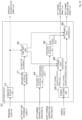
- the coding device 100 includes a downmix unit 110, a left channel subtraction gain estimation unit 120, a left channel signal subtraction unit 130, a right channel subtraction gain estimation unit 140, a right channel signal subtraction unit 150, a monaural coding unit 160, and a stereo coding unit 170.
- the coding device 100 codes input 2-channel stereo sound signals in the time domain in frame units having a prescribed time length of, for example, 20 ms, to obtain and output the monaural code CM, the left channel subtraction gain code C ⁇ , the right channel subtraction gain code C ⁇ , and the stereo code CS described later.
- the 2-channel stereo sound signals in the time domain input to the coding device are, for example, digital audio signals or acoustic signals obtained by collecting sounds such as voice and music with each of two microphones and performing AD conversion, and consist of input sound signals of the left channel and input sound signals of the right channel.
- the codes output by the coding device that is, the monaural code CM, the left channel subtraction gain code C ⁇ , the right channel subtraction gain code C ⁇ , and the stereo code CS are input to the decoding device.
- the coding device 100 performs the processes of steps S 110 to S170 illustrated in Fig. 2 for each frame.
- the input sound signals of the left channel input to the coding device 100 and the input sound signals of the right channel input to the coding device 100 are input to the downmix unit 110.
- the downmix unit 110 obtains and outputs downmix signals which are signals obtained by mixing the input sound signals of the left channel and the input sound signals of the right channel, from the input sound signals of the left channel and the input sound signals of the right channel input (step S 110).
- T is a positive integer, and, for example, if the frame length is 20 ms and the sampling frequency is 32 kHz, then T is 640.
- the downmix unit 110 obtains and outputs a sequence of average values of the respective sample values for corresponding samples of the input sound signals of the left channel and the input sound signals of the right channel input, as downmix signals x M (1), x M (2), ..., x M (T).
- x M (1), x M (2), ..., x M (T) downmix signals x M (1), x M (2), ..., x M (T).
- the input sound signals x L (1), x L (2), ..., x L (T) of the left channel input to the coding device 100, and the downmix signals x M (1), x M (2), ..., x M (T) output by the downmix unit 110 are input to the left channel subtraction gain estimation unit 120.
- the left channel subtraction gain estimation unit 120 obtains and outputs the left channel subtraction gain ⁇ and the left channel subtraction gain code C ⁇ , which is the code representing the left channel subtraction gain ⁇ , from the input sound signals of the left channel and the downmix signals input (step S120).
- the left channel subtraction gain estimation unit 120 determines the left channel subtraction gain ⁇ and the left channel subtraction gain code C ⁇ by a well-known method such as that illustrated in the method of obtaining the amplitude ratio g in PTL 1 or the method of coding the amplitude ratio g, or a newly proposed method based on the principle for minimizing quantization errors.
- a well-known method such as that illustrated in the method of obtaining the amplitude ratio g in PTL 1 or the method of coding the amplitude ratio g, or a newly proposed method based on the principle for minimizing quantization errors.
- the principle for minimizing quantization errors and the method based on this principle are described below.
- the input sound signals x L (1), x L (2), ..., x L (T) of the left channel input to the coding device 100, the downmix signals x M (1), x M (2), ..., x M (T) output by the downmix unit 110, and the left channel subtraction gain ⁇ output by the left channel subtraction gain estimation unit 120 are input to the left channel signal subtraction unit 130.
- the left channel signal subtraction unit 130 obtains and outputs a sequence of values x L (t) - ⁇ ⁇ x M (t) obtained by subtracting the value ⁇ ⁇ x M (t), obtained by multiplying the sample value x M (t) of the downmix signal and the left channel subtraction gain ⁇ , from the sample value x L (t) of the input sound signal of the left channel, for each corresponding sample t, as left channel difference signals y L (1), y L (2), ..., y L (T) (step S130).
- y L (t) x L (t) - ⁇ ⁇ x M (t).
- the left channel signal subtraction unit 130 may use the unquantized downmix signal x M (t) obtained by the downmix unit 110 rather than a quantized downmix signal that is a local decoded signal of monaural coding.
- a means for obtaining a local decoded signal corresponding to the monaural code CM may be provided in the subsequent stage of the monaural coding unit 160 of the coding device 100 or in the monaural coding unit 160, and in the left channel signal subtraction unit 130, quantized downmix signals ⁇ x M (1), ⁇ x M (2), ..., ⁇ x M (T) which are local decoded signals for monaural coding may be used to obtain the left channel difference signals in place of the downmix signals x M (1), x M (2), ..., x M (T), as in the case of a conventional coding device such as PTL 1.
- the input sound signals x R (1), x R (2), ..., x R (T) of the right channel input to the coding device 100, and the downmix signals x M (1), x M (2), ..., x M (T) output by the downmix unit 110 are input to the right channel subtraction gain estimation unit 140.
- the right channel subtraction gain estimation unit 140 obtains and outputs the right channel subtraction gain ⁇ and the right channel subtraction gain code C ⁇ , which is the code representing the right channel subtraction gain ⁇ , from the input sound signals of the right channel and the downmix signals input (step S140).
- the right channel subtraction gain estimation unit 140 determines the right channel subtraction gain ⁇ and the right channel subtraction gain code C ⁇ by a well-known method such as that illustrated in the method of obtaining the amplitude ratio g in PTL 1 or the method of coding the amplitude ratio g, or a newly proposed method based on the principle for minimizing quantization errors.
- a well-known method such as that illustrated in the method of obtaining the amplitude ratio g in PTL 1 or the method of coding the amplitude ratio g, or a newly proposed method based on the principle for minimizing quantization errors.
- the principle for minimizing quantization errors and the method based on this principle are described below.
- the input sound signals x R (1), x R (2), ..., x R (T) of the right channel input to the coding device 100, the downmix signals x M (1), x M (2), ..., x M (T) output by the downmix unit 110, and the right channel subtraction gain ⁇ output by the right channel subtraction gain estimation unit 140 are input to the right channel signal subtraction unit 150.
- the right channel signal subtraction unit 150 obtains and outputs a sequence of values x R (t) - ⁇ ⁇ x M (t) obtained by subtracting the value ⁇ ⁇ x M (t), obtained by multiplying the sample value x M (t) of the downmix signal and the right channel subtraction gain ⁇ , from the sample value x R (t) of the input sound signal of the right channel, for each corresponding sample t, as right channel difference signals y R (1), y R (2), ..., y R (T) (step S150).
- y R (t) x R (t) - ⁇ ⁇ x M (t).
- the right channel signal subtraction unit 150 Similar to the left channel signal subtraction unit 130, in the coding device 100, in order to avoid requiring latency or an arithmetic processing amount for obtaining a local decoded signal, the right channel signal subtraction unit 150 only needs to use the unquantized downmix signal x M (t) obtained by the downmix unit 110 rather than a quantized downmix signal that is a local decoded signal of monaural coding.
- a means for obtaining a local decoded signal corresponding to the monaural code CM may be provided in the subsequent stage of the monaural coding unit 160 of the coding device 100 or in the monaural coding unit 160, and in the right channel signal subtraction unit 150, similar to the left channel signal subtraction unit 130, quantized downmix signals ⁇ x M (1), ⁇ x M (2), ..., ⁇ x M (T) which are local decoded signals for monaural coding may be used to obtain the right channel difference signals in place of the downmix signals x M (1), x M (2), ..., x M (T), as in the case of a conventional coding device such as PTL 1.
- the downmix signals x M (1), x M (2), ..., x M (T) output by the downmix unit 110 are input to the monaural coding unit 160.
- the monaural coding unit 160 codes the input downmix signals with b M bits in a prescribed coding scheme to obtain and output the monaural code CM (step S160).
- the monaural code CM with b M bits is obtained and output from the downmix signals x M (1), x M (2), ..., x M (T) of the input T samples.
- Any coding scheme may be used as the coding scheme, for example, a coding scheme such as the 3GPP EVS standard is used.
- the left channel difference signals y L (1), y L (2), ..., y L (T) output by the left channel signal subtraction unit 130, and the right channel difference signals y R (1), y R (2), ..., y R (T) output by the right channel signal subtraction unit 150 are input to the stereo coding unit 170.
- the stereo coding unit 170 codes the input left channel difference signals and the right channel difference signals in a prescribed coding scheme with a total of b s bits to obtain and output the stereo code CS (step S170).
- the stereo code CS with the total of b S bits are obtained from the left channel difference signals y L (1), y L (2), ..., y L (T) of the input T samples and the right channel difference signals y R (1), y R (2), ..., y R (T) of the input T samples, and output.
- Any coding scheme may be used as the coding scheme, for example, a stereo coding scheme corresponding to the stereo decoding scheme of the MPEG-4 AAC standard may be used, or a coding scheme of independently coding input left channel difference signals and input right channel difference signals may be used, and a combination of all the codes obtained by the coding is used as a "stereo code CS".
- the stereo coding unit 170 codes the left channel difference signals with b L bits and codes the right channel difference signals with b R bits.
- the stereo coding unit 170 obtains the left channel difference code CL with b L bits from the left channel difference signals y L (1), y L (2), ..., y L (T) of the input T samples, obtains the right channel difference code CR with b R bits from the right channel difference signals y R (1), y R (2), ..., y R (T) of the input T samples, and outputs the combination of the left channel difference code CL and the right channel difference code CR as the stereo code CS.
- the sum of b L bits and b R bits is b S bits.
- the stereo coding unit 170 codes the left channel difference signals and the right channel difference signals with a total of b S bit. In other words, the stereo coding unit 170 obtains and outputs the stereo code CS with b S bits from the left channel difference signals y L (1), y L (2), ..., y L (T) of the input T samples and the right channel difference signals y R (1), y R (2), ..., y R (T) of the input T samples.
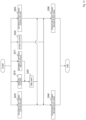
- the decoding device 200 includes a monaural decoding unit 210, a stereo decoding unit 220, a left channel subtraction gain decoding unit 230, a left channel signal addition unit 240, a right channel subtraction gain decoding unit 250, and a right channel signal addition unit 260.
- the decoding device 200 decodes the input monaural code CM, the left channel subtraction gain code C ⁇ , the right channel subtraction gain code C ⁇ , and the stereo code CS in the frame units having the same time length as that of the corresponding coding device 100, to obtain and output 2-channel stereo decoded sound signals (left channel decoded sound signals and right channel decoded sound signals described below) in the time domain in frame units.
- the decoding device 200 may also output monaural decoded sound signals (monaural decoded sound signals described below) in the time domain, as indicated by the dashed lines in Fig. 3 .
- the decoded sound signals output by the decoding device 200 are, for example, DA converted and played by a speaker to be heard.
- the decoding device 200 performs the processes of steps S210 to S260 illustrated in Fig. 4 for each frame.
- the monaural code CM input to the decoding device 200 is input to the monaural decoding unit 210.
- the monaural decoding unit 210 decodes the input monaural code CM in a prescribed decoding scheme to obtain and output monaural decoded sound signals ⁇ x M (1), ⁇ x M (2), ..., ⁇ x M (T) (step S210).
- a decoding scheme corresponding to the coding scheme used by the monaural coding unit 160 of the corresponding coding device 100 is used as the prescribed decoding scheme.
- the number of bits of the monaural code CM is b M .
- the stereo code CS input to the decoding device 200 is input to the stereo decoding unit 220.
- the stereo decoding unit 220 decodes the input stereo code CS in a prescribed decoding scheme to obtain and output left channel decoded difference signals ⁇ y L (1), ⁇ y L (2), ..., ⁇ y L (T), and right channel decoded difference signals ⁇ y R (1), ⁇ y R (2), ..., ⁇ y R (T) (step S220).
- a decoding scheme corresponding to the coding scheme used by the stereo coding unit 170 of the corresponding coding device 100 is used as the prescribed decoding scheme.
- the total number of bits of the stereo code CS is b S .
- the left channel subtraction gain code C ⁇ input to the decoding device 200 is input to the left channel subtraction gain decoding unit 230.
- the left channel subtraction gain decoding unit 230 decodes the left channel subtraction gain code C ⁇ to obtain and output the left channel subtraction gain ⁇ (step S230).
- the left channel subtraction gain decoding unit 230 decodes the left channel subtraction gain code C ⁇ in a decoding method corresponding to the method used by the left channel subtraction gain estimation unit 120 of the corresponding coding device 100 to obtain the left channel subtraction gain ⁇ .
- the monaural decoded sound signals ⁇ x M (1), ⁇ x M (2), ..., ⁇ x M (T) output by the monaural decoding unit 210, the left channel decoded difference signals ⁇ y L (1), ⁇ y L (2), ..., ⁇ y L (T) output by the stereo decoding unit 220, and the left channel subtraction gain ⁇ output by the left channel subtraction gain decoding unit 230 are input to the left channel signal addition unit 240.
- the left channel signal addition unit 240 obtains and outputs a sequence of values ⁇ y L (t) + ⁇ ⁇ ⁇ x M (T) obtained by adding the sample value ⁇ y L (t) of the left channel decoded difference signal and the value ⁇ ⁇ ⁇ x M (T) obtained by multiplying the sample value ⁇ x M (T) of the monaural decoded sound signal and the left channel subtraction gain ⁇ , for each corresponding sample t, as left channel decoded sound signals ⁇ x L (1), ⁇ x L (2), ..., ⁇ x L (T) (step S240).
- ⁇ x L (t) ⁇ y L (t) + ⁇ ⁇ ⁇ x M (t).
- the right channel subtraction gain code C ⁇ input to the decoding device 200 is input to the right channel subtraction gain decoding unit 250.
- the right channel subtraction gain decoding unit 250 decodes the right channel subtraction gain code C ⁇ to obtain and output the right channel subtraction gain ⁇ (step S250).
- the right channel subtraction gain decoding unit 250 decodes the right channel subtraction gain code C ⁇ in a decoding method corresponding to the method used by the right channel subtraction gain estimation unit 140 of the corresponding coding device 100 to obtain the right channel subtraction gain ⁇ .
- the monaural decoded sound signals ⁇ x M (1), ⁇ x M (2), ..., ⁇ x M (T) output by the monaural decoding unit 210, the right channel decoded difference signals ⁇ y R (1), ⁇ y R (2), ..., ⁇ y R (T) output by the stereo decoding unit 220, and the right channel subtraction gain ⁇ output by the right channel subtraction gain decoding unit 250 are input to the right channel signal addition unit 260.
- the right channel signal addition unit 260 obtains and outputs a sequence of values ⁇ y R (t) + ⁇ ⁇ ⁇ x M (T) obtained by adding the sample value ⁇ y R (t) of the right channel decoded difference signal and the value ⁇ ⁇ ⁇ x M (t) obtained by multiplying the sample value ⁇ x M (T) of the monaural decoded sound signal and the right channel subtraction gain ⁇ , for each corresponding sample t, as right channel decoded sound signals ⁇ x R (1), ⁇ x R (2), ..., ⁇ x R (T) (step S260).
- ⁇ x R (t) ⁇ y R (t) + ⁇ ⁇ ⁇ x M (t).
- the number of bits b L used for the coding of the left channel difference signals and the number of bits b R used for the coding of the right channel difference signals may not be explicitly determined, but in the following, the description is made assuming that the number of bits used for the coding of the left channel difference signals is b L , and the number of bits used for the coding of the right channel difference signal is b R . In the following, mainly the left channel will be described, but the description similarly applies to the right channel.
- the coding device 100 described above codes the left channel difference signals y L (1), y L (2), ..., y L (T) having values obtained by subtracting the value obtained by multiplying each sample value of the downmix signals x M (1), x M (2), ..., x M (T) and the left channel subtraction gain ⁇ , from each sample value of the input sound signals x L (1), x L (2), ..., x L (T) of the left channel, with b L bits, and codes the downmix signals x M (1), x M (2), ..., x M (T) with b M bits.
- the decoding device 200 described above decodes the left channel decoded difference signals ⁇ y L (1), ⁇ y L (2), ..., ⁇ y L (T) from the b L bit code (hereinafter also referred to as "quantized left channel difference signals”) and decodes the monaural decoded sound signals ⁇ x M (1), ⁇ x M (2), ..., ⁇ x M (T) from the b M bit code (hereinafter also referred to as "quantized downmix signals”), and then adds the value obtained by multiplying each sample value of the quantized downmix signals ⁇ x M (1), ⁇ x M (2), ..., ⁇ x M (T) obtained by the decoding by the left channel subtraction gain ⁇ , to each sample value of the quantized left channel difference signals ⁇ y L (1), ⁇ y L (2), ..., ⁇ y L (T) obtained by the decoding, to obtain the left channel decoded sound signals ⁇ x L (1), ⁇ x L (2), ..., ⁇ x L (T), which are
- the energy of the quantization errors (hereinafter referred to as "quantization errors generated by coding" for convenience) possessed by the decoded signals obtained by coding and decoding input signals is roughly proportional to the energy of the input signals in many cases, and tends to be exponentially smaller with respect to the value of the number of bits per sample used for the coding.
- the average energy of the quantization errors per sample resulting from the coding of the left channel difference signals can be estimated using a positive number ⁇ L 2 as in Expression (1-0-1) below
- the average energy of the quantization errors per sample resulting from the coding of the downmix signals can be estimated using a positive number ⁇ M 2 as in Expression (1-0-2) below.
- each sample values of the input sound signals x L (1), x L (2), ..., x L (T) of the left channel and the downmix signals x M (1), x M (2), ..., x M (T) are close values such that the input sound signals x L (1), x L (2), ..., x L (T) of the left channel and the downmix signals x M (1), x M (2), ..., x M (T) can be regarded as the same sequence.
- each sample value of the left channel difference signals y L (1), y L (2), ..., y L (T) is equivalent to the value obtained by multiplying a corresponding sample value of the downmix signals x M (1), x M (2), ..., x M (T) by (1 - ⁇ ).
- the average energy of the quantization errors per sample possessed by the signals added to the quantized left channel difference signals in the decoding device that is, the average energy of the quantization errors per sample possessed by a sequence of values obtained by multiplying each sample value of the quantized downmix signals obtained by the decoding and the left channel subtraction gain ⁇ can be estimated as in Expression (1-2) below. [Math. 4] ⁇ 2 ⁇ M 2 2 ⁇ 2 b M T
- the average energy of the quantization errors per sample possessed by the decoded sound signals of the left channel is estimated by the sum of Expressions (1-1) and (1-2).
- the left channel subtraction gain estimation unit 120 only needs to calculate the left channel subtraction gain ⁇ by Equation (1-3).
- the left channel subtraction gain ⁇ obtained in Equation (1-3) is a value greater than 0 and less than 1, is 0.5 when b L and b M , which are the two numbers of bits used for the coding, are equal, is a value closer to 0 than 0.5 as the number of bits b L for coding the left channel difference signals is greater than the number of bits b M for coding the downmix signals, and is a value closer to 1 than 0.5 as the number of bits b M for coding the downmix signals is greater than the number of bits b L for coding the left channel difference signals.
- Equation (1-3-2) 2 ⁇ 2 b R T 2 ⁇ 2 b R T + 2 ⁇ 2 b M T
- the right channel subtraction gain ⁇ obtained in Equation (1-3-2) is a value greater than 0 and less than 1, is 0.5 when b R and b M , which are the two numbers of bits used for the coding, are equal, is a value closer to 0 than 0.5 as the number of bits b R for coding the right channel difference signals is greater than the number of bits b M for coding the downmix signals, and is a value closer to 1 than 0.5 as the number of bits b M for coding the downmix signals is greater than the number of bits b R for coding the right channel difference signals.
- Equation (1-4) The normalized inner product value r L of the input sound signals x L (1), x L (2), ..., x L (T) of the left channel and the downmix signal x M (1), x M (2), ..., x M (T) is represented by Equation (1-4) below. [Math.
- the normalized inner product value r L obtained by Equation (1-4) is an actual value, and when each sample value of the downmix signals x M (1), x M (2), ..., x M (T) is multiplied by an actual value r L ' to obtain a sequence of sample values r L ' ⁇ x M (1), r L ' ⁇ x M (2), ..., r L ' ⁇ x M (T), the normalized inner product value r L is the same value as the actual value rL', where the energy of the sequence x L (1) - r L ' ⁇ x M (1), x L (2) - r L ' ⁇ x M (2), ..., x L (T) - r L ' ⁇ x M (T) obtained by the difference between the obtained sequence of the sample values and each sample value
- the orthogonal signals x L '(1), x L '(2), ..., x L '(T) indicate orthogonality with respect to the downmix signals x M (1), x M (2), ..., x M (T), in other words, the property that the inner product is 0, the energy of the left channel difference signals is expressed as the sum of the energy of the downmix signals multiplied by (r L - ⁇ ) 2 and the energy of the orthogonal signals.
- the average energy of the quantization errors per sample resulting from coding the left channel difference signals with b L bits can be estimated using a positive number ⁇ 2 as in Expression (1-5) below. [Math. 8] r L ⁇ ⁇ 2 ⁇ M 2 + ⁇ 2 2 ⁇ 2 b L T
- the average energy of the quantization errors per sample possessed by the decoded sound signals of the left channel is estimated by the sum of Expressions (1-5) and (1-2).
- the left channel subtraction gain estimation unit 120 in order to minimize the quantization errors of the decoded sound signals of the left channel, the left channel subtraction gain estimation unit 120 only needs to calculate the left channel subtraction gain ⁇ by Equation (1-6). In other words, considering this principle for minimizing the energy of the quantization errors, the left channel subtraction gain ⁇ should use a value obtained by multiplying the normalized inner product value r L and a correction coefficient that is a value determined by b L and b M , which are the numbers of bits used for the coding.
- the correction coefficient is a value greater than 0 and less than 1, is 0.5 when the number of bits b L for coding the left channel difference signals and the number of bits b M for coding the downmix signals are the same, is closer to 0 than 0.5 as the number of bits b L for coding the left channel difference signals is greater than the number of bits b M for coding the downmix signals, and is closer to 1 than 0.5 as the number of bits b L for coding the left channel difference signals is less than the number of bits b M for coding the downmix signals.
- the right channel subtraction gain estimation unit 140 calculates the right channel subtraction gain ⁇ by Equation (1-6-2) below.
- ⁇ 2 ⁇ 2 b R T 2 ⁇ 2 b R T + 2 ⁇ 2 b M T r R
- r R is a normalized inner product value of the input sound signals x R (1), x R (2), ..., x R (T) of the right channel and the downmix signals x M (1), x M (2), ..., x M (T), which is expressed by Equation (1-4-2) below.
- the right channel subtraction gain ⁇ should use a value obtained by multiplying the normalized inner product value r R and a correction coefficient that is a value determined by b R and b M , which are the numbers of bits used for the coding.
- the correction coefficient is a value greater than 0 and less than 1, is a value closer to 0 than 0.5 as the number of bits b R for coding the right channel difference signals is greater than the number of bits b M for coding the downmix signals, and closer to 1 than 0.5 as the number of bits for coding the right channel difference signals is less than the number of bits for coding the downmix signals.
- the left channel subtraction gain estimation unit 120 and the right channel subtraction gain estimation unit 140 configured to estimate a subtraction gain in the coding device 100
- the left channel subtraction gain decoding unit 230 and the right channel subtraction gain decoding unit 250 configured to decode a subtraction gain in the decoding device 200
- Example 1 is based on the principle for minimizing the energy of the quantization errors possessed by the decoded sound signals of the left channel, including a case in which the input sound signals x L (1), x L (2), ..., x L (T) of the left channel and the downmix signals x M (1), x M (2), ..., x M (T) are not regarded as the same sequence, and the principle for minimizing the energy of the quantization errors possessed by the decoded sound signals of the right channel, including a case in which the input sound signals x R (1), x R (2), ..., x R (T) of the right channel and the downmix signals x M (1), x M (2), ..., x M (T) are not regarded as the same sequence.
- the left channel subtraction gain estimation unit 120 performs steps S120-11 to S120-14 below illustrated in Fig. 5 .
- the left channel subtraction gain estimation unit 120 first obtains the normalized inner product value r L for the input sound signals of the left channel of the downmix signals by Equation (1-4) from the input sound signals x L (1), x L (2), ..., x L (T) of the left channel and the downmix signals x M (1), x M (2), ..., x M (T) input (step S120-11).
- the left channel subtraction gain estimation unit 120 obtains the left channel correction coefficient c L by Equation (1-7) below by using the number of bits b L used for the coding of the left channel difference signals y L (1), y L (2), ..., y L (T) in the stereo coding unit 170, the number of bits b M used for the coding of the downmix signals x M (1), x M (2), ..., x M (T) in the monaural coding unit 160, and the number of samples T per frame (step S120-12). [Math.
- c L 2 ⁇ 2 b L T 2 ⁇ 2 b L T + 2 ⁇ 2 b M T
- the left channel subtraction gain estimation unit 120 then obtains a value obtained by multiplying the normalized inner product value r L obtained in step S120-11 and the left channel correction coefficient c L obtained in step S120-12 (step S120-13).
- the left channel subtraction gain estimation unit 120 then obtains a candidate closest to the multiplication value c L ⁇ r L obtained in step S120-13 (quantized value of the multiplication value c L ⁇ r L ) of the stored candidates ⁇ cand (1), ..., ⁇ cand (A) of the left channel subtraction gain as the left channel subtraction gain ⁇ , and obtains the code corresponding to the left channel subtraction gain ⁇ of the stored codes C ⁇ cand (1), ..., C ⁇ cand (A) as the left channel subtraction gain code C ⁇ (step S120-14).
- the number of bits b L used for the coding of the left channel difference signals y L (1), y L (2), ..., y L (T) in the stereo coding unit 170 is not explicitly determined, it is only needed to use half of the number of bits b s of the stereo code CS output by the stereo coding unit 170 (that is, b s /2) as the number of bits b L .
- the left channel correction coefficient c L may be a value greater than 0 and less than 1, may be 0.5 when the number of bits b L used for the coding of the left channel difference signals y L (1), y L (2), ..., y L (T) and the number of bits b M used for the coding of the downmix signals x M (1), x M (2), ..., x M (T) are the same, and may be a value closer to 0 than 0.5 as the number of bits b L is greater than the number of bits b M and closer to 1 than 0.5 as the number of bits b L is less than the number of bits b M .
- the right channel subtraction gain estimation unit 140 performs steps S140-11 to S140-14 below illustrated in Fig. 5 .
- the right channel subtraction gain estimation unit 140 first obtains the normalized inner product value r R for the input sound signals of the right channel of the downmix signals by Equation (1-4-2) from the input sound signals x R (1), x R (2), ..., x R (T) of the right channel and the downmix signals x M (1), x M (2), ..., x M (T) input (step S140-11).
- the right channel subtraction gain estimation unit 140 obtains the right channel correction coefficient c R by Equation (1-7-2) below by using the number of bits b R used for the coding of the right channel difference signals y R (1), y R (2), ..., y R (T) in the stereo coding unit 170, the number of bits b M used for the coding of the downmix signals x M (1), x M (2), ..., x M (T) in the monaural coding unit 160, and the number of samples T per frame (step S140-12).
- c R 2 ⁇ 2 b R T 2 ⁇ 2 b R T + 2 ⁇ 2 b M T
- the right channel subtraction gain estimation unit 140 then obtains a value obtained by multiplying the normalized inner product value r R obtained in step S140-11 and the right channel correction coefficient c R obtained in step S140-12 (step S140-13).
- the right channel subtraction gain estimation unit 140 then obtains a candidate closest to the multiplication value c R ⁇ r R obtained in step S140-13 (quantized value of the multiplication value c R ⁇ r R ) of the stored candidates ⁇ cand (1), ..., ⁇ cand (B) of the right channel subtraction gain as the right channel subtraction gain ⁇ , and obtains the code corresponding to the right channel subtraction gain ⁇ of the stored codes C ⁇ cand (1), ..., C ⁇ cand (B) as the right channel subtraction gain code C ⁇ (step S140-14).
- the number of bits b R used for the coding of the right channel difference signals y R (1), y R (2), ..., y R (T) in the stereo coding unit 170 is not explicitly determined, it is only needed to use half of the number of bits b s of the stereo code CS output by the stereo coding unit 170 (that is, b s /2), as the number of bits b R .
- the right channel correction coefficient c R may be a value greater than 0 and less than 1, may be 0.5 when the number of bits b R used for the coding of the right channel difference signals y R (1), y R (2), ..., y R (T) and the number of bits b M used for the coding of the downmix signals x M (1), x M (2), ..., x M (T) are the same, and may be a value closer to 0 than 0.5 as the number of bits b R is greater than the number of bits b M and closer to 1 than 0.5 as the number of bits b R is less than the number of bits b M .
- the left channel subtraction gain decoding unit 230 obtains a candidate of the left channel subtraction gain corresponding to an input left channel subtraction gain code C ⁇ of the stored codes C ⁇ cand (1), ..., C ⁇ cand (A) as the left channel subtraction gain ⁇ (step S230-11).
- the right channel subtraction gain decoding unit 250 obtains a candidate of the right channel subtraction gain corresponding to an input right channel subtraction gain code C ⁇ of the stored codes C ⁇ cand (1), ..., C ⁇ cand (B) as the right channel subtraction gain ⁇ (step S250-11).
- the left channel and the right channel only needs to use the same candidates or codes of subtraction gain, and by using the same value for the above-described A and B, the set of the candidates of the left channel subtraction gain ⁇ cand (a) and the codes C ⁇ cand (a) corresponding to the candidates stored in the left channel subtraction gain estimation unit 120 and the left channel subtraction gain decoding unit 230 and the set of the candidates of the right channel subtraction gain ⁇ cand (b) and the codes C ⁇ cand (b) corresponding to the candidates stored in the right channel subtraction gain estimation unit 140 and the right channel subtraction gain decoding unit 250 may be the same.
- the correction coefficient c L can be calculated as the same value for both the coding device 100 and the decoding device 200.
- the left channel subtraction gain ⁇ may be obtained by multiplying the quantized value ⁇ r L of the inner product value normalized by the coding device 100 and the decoding device 200 by the correction coefficient c L . This similarly applies to the right channel.
- This mode will be described as a modified example of Example 1.
- the left channel subtraction gain estimation unit 120 first obtains the normalized inner product value r L for the input sound signals of the left channel of the downmix signals by Equation (1-4) from the input sound signals x L (1), x L (2), ..., x L (T) of the left channel and the downmix signals x M (1), x M (2), ..., x M (T) input (step S120-11).
- the left channel subtraction gain estimation unit 120 then obtains a candidate ⁇ r L closest to the normalized inner product value r L (quantized value of the normalized inner product value r L ) obtained in step S120-11 of the stored candidates r Lcand (1), ..., r Lcand (A) of the normalized inner product value of the left channel, and obtains the code corresponding to the closest candidate ⁇ r L of the stored codes C ⁇ cand (1), ..., C ⁇ cand (A) as the left channel subtraction gain code C ⁇ (step S120-15).
- the left channel subtraction gain estimation unit 120 obtains the left channel correction coefficient c L by Equation (1-7) by using the number of bits b L used for the coding of the left channel difference signals y L (1), y L (2), ..., y L (T) in the stereo coding unit 170, the number of bits b M used for the coding of the downmix signals x M (1), x M (2), ..., x M (T) in the monaural coding unit 160, and the number of samples T per frame (step S120-12).
- the left channel subtraction gain estimation unit 120 then obtains a value obtained by multiplying the quantized value of the normalized inner product value ⁇ r L obtained in step S120-15 and the left channel correction coefficient c L obtained in step S120-12 as the left channel subtraction gain ⁇ (step S120-16).
- the right channel subtraction gain estimation unit 140 first obtains the normalized inner product value r R for the input sound signals of the right channel of the downmix signals by Equation (1-4-2) from the input sound signals x R (1), x R (2), ..., x R (T) of the right channel and the downmix signals x M (1), x M (2), ..., x M (T) input (step S140-11).
- the right channel subtraction gain estimation unit 140 then obtains a candidate ⁇ r R closest to the normalized inner product value r R (quantized value of the normalized inner product value r R ) obtained in step S140-11 of the stored candidates r Rcand (1), ..., r Rcand (B) of the normalized inner product value of the right channel, and obtains the code corresponding to the closest candidate ⁇ r R of the stored codes C ⁇ cand (1), ..., C ⁇ cand (B) as the right channel subtraction gain code C ⁇ (step S140-15).
- the right channel subtraction gain estimation unit 140 obtains the right channel correction coefficient c R by Equation (1-7-2) by using the number of bits b R used for the coding of the right channel difference signals y R (1), y R (2), ..., y R (T) in the stereo coding unit 170, the number of bits b M used for the coding of the downmix signals x M (1), x M (2), ..., x M (T) in the monaural coding unit 160, and the number of samples T per frame (step S140-12).
- the right channel subtraction gain estimation unit 140 then obtains a value obtained by multiplying the quantized value of the normalized inner product value ⁇ r R obtained in step S140-15 and the right channel correction coefficient c R obtained in step S140-12, as the right channel subtraction gain ⁇ (step S140-16).
- the left channel subtraction gain decoding unit 230 performs steps S230-12 to S230-14 below illustrated in Fig. 7 .
- the left channel subtraction gain decoding unit 230 obtains a candidate of the normalized inner product value of the left channel corresponding to an input left channel subtraction gain code C ⁇ of the stored codes C ⁇ cand (1), ..., C ⁇ cand (A) as the decoded value ⁇ r L of the normalized inner product value of the left channel (step S230-12).
- the left channel subtraction gain decoding unit 230 obtains the left channel correction coefficient c L by Equation (1-7) by using the number of bits b L used for the decoding of the left channel decoded difference signals ⁇ y L (1), ⁇ y L (2), ..., ⁇ y L (T) in the stereo decoding unit 220, the number of bits b M used for the decoding of the monaural decoded sound signals ⁇ x M (1), ⁇ x M (2), ..., ⁇ x M (T) in the monaural decoding unit 210, and the number of samples T per frame (step S230-13).
- the left channel subtraction gain decoding unit 230 then obtains a value obtained by multiplying the decoded value of the normalized inner product value ⁇ r L obtained in step S230-12 and the left channel correction coefficient c L obtained in step S230-13, as the left channel subtraction gain ⁇ (step S230-14).
- the stereo code CS is a combination of the left channel difference code CL and the right channel difference code CR
- the number of bits b L used for the decoding of the left channel decoded difference signals ⁇ y L (1), ⁇ y L (2), ..., ⁇ y L (T) in the stereo decoding unit 220 is the number of bits of the left channel difference code CL.
- the number of bits b L used for the decoding of the left channel decoded difference signals ⁇ y L (1), ⁇ y L (2), ..., ⁇ y L (T) in the stereo decoding unit 220 is not explicitly determined, it is only needed to use half of the number of bits b s of the stereo code CS input to the stereo decoding unit 220 (that is, b s /2), as the number of bits b L .
- the number of bits b M used for the decoding of the monaural decoded sound signals ⁇ x M (1), ⁇ x M (2), ..., ⁇ x M (T) in the monaural decoding unit 210 is the number of bits of the monaural code CM.
- the left channel correction coefficient c L may be a value greater than 0 and less than 1, may be 0.5 when the number of bits b L used for the decoding of the left channel decoded difference signals ⁇ y L (1), ⁇ y L (2), ..., ⁇ y L (T) and the number of bits b M used for the decoding of the monaural decoded sound signals ⁇ x M (1), ⁇ x M (2), ..., ⁇ x M (T) are the same, and may be a value closer to 0 than 0.5 as the number of bits b L is greater than the number of bits b M and closer to 1 than 0.5 as the number of bits b L is less than the number of bits b M .
- the right channel subtraction gain decoding unit 250 performs steps S250-12 to S250-14 below illustrated in Fig. 7 .
- the right channel subtraction gain decoding unit 250 obtains a candidate of the normalized inner product value of the right channel corresponding to an input right channel subtraction gain code C ⁇ of the stored codes C ⁇ cand (1), ..., C ⁇ cand (B) as the decoded value ⁇ r R of the normalized inner product value of the right channel (step S250-12).
- the right channel subtraction gain decoding unit 250 obtains the right channel correction coefficient c R by Equation (1-7-2) by using the number of bits b R used for the decoding of the right channel decoded difference signals ⁇ y R (1), ⁇ y R (2), ..., ⁇ y R (T) in the stereo decoding unit 220, the number of bits b M used for the decoding of the monaural decoded sound signals ⁇ x M (1), ⁇ x M (2), ..., ⁇ x M (T) in the monaural decoding unit 210, and the number of samples T per frame (step S250-13).
- the right channel subtraction gain decoding unit 250 then obtains a value obtained by multiplying the decoded value of the normalized inner product value ⁇ r R obtained in step S250-12 and the right channel correction coefficient c R obtained in step S250-13, as the right channel subtraction gain ⁇ (step S250-14).
- the stereo code CS is a combination of the left channel difference code CL and the right channel difference code CR
- the number of bits b R used for the decoding of the right channel decoded difference signals ⁇ y R (1), ⁇ y R (2), ..., ⁇ y R (T) in the stereo decoding unit 220 is the number of bits of the right channel difference code CR.
- the number of bits b R used for the decoding of the right channel decoded difference signals ⁇ y R (1), ⁇ y R (2), ..., ⁇ y R (T) in the stereo decoding unit 220 is not explicitly determined, it is only needed to use half of the number of bits b s of the stereo code CS input to the stereo decoding unit 220 (that is, b s /2), as the number of bits b R .
- the number of bits b M used for the decoding of the monaural decoded sound signals ⁇ x M (1), ⁇ x M (2), ..., ⁇ x M (T) in the monaural decoding unit 210 is the number of bits of the monaural code CM.
- the right channel correction coefficient c R may be a value greater than 0 and less than 1, may be 0.5 when the number of bits b R used for the decoding of the right channel decoded difference signals ⁇ y R (1), ⁇ y R (2), ..., ⁇ y R (T) and the number of bits b M used for the decoding of the monaural decoded sound signals ⁇ x M (1), ⁇ x M (2), ..., ⁇ x M (T) are the same, and may be a value closer to 0 than 0.5 as the number of bits b R is greater than the number of bits b M and closer to 1 than 0.5 as the number of bits b R is less than the number of bits b M .
- the left channel and the right channel only needs to use the same candidates or codes of normalized inner product value, and by using the same value for the above-described A and B, the set of the candidate of the normalized inner product value of the left channel r Lcand (a) and the code C ⁇ cand (a) corresponding to the candidate stored in the left channel subtraction gain estimation unit 120 and the left channel subtraction gain decoding unit 230 and the set of the candidate of the normalized inner product value of the right channel r Rcand (b) and the code C ⁇ cand (b) corresponding to the candidate stored in the right channel subtraction gain estimation unit 140 and the right channel subtraction gain decoding unit 250 may be the same.
- the code C ⁇ is referred to as a left channel subtraction gain code because the code C ⁇ is substantially a code corresponding to the left channel subtraction gain ⁇ , for the purpose of matching the wording in the descriptions of the coding device 100 and the decoding device 200, and the like, but the code C ⁇ may also be referred to as a left channel inner product code or the like because the code C ⁇ represents a normalized inner product value. This similarly applies to the code C ⁇ , and the code C ⁇ may be referred to as a right channel inner product code or the like.
- Example 2 An example of using a value considering input values of past frames as the normalized inner product value will be described as Example 2.
- Example 2 does not strictly guarantee the optimization within the frame, that is, the minimization of the energy of the quantization errors possessed by the decoded sound signals of the left channel and the minimization of the energy of the quantization errors possessed by the decoded sound signals of the right channel, but reduces abrupt fluctuation of the left channel subtraction gain ⁇ between frames and abrupt fluctuation of the right channel subtraction gain ⁇ between frames, and reduces noise generated in the decoded sound signals due to the fluctuation.
- Example 2 considers the auditory quality of the decoded sound signals in addition to reducing the energy of the quantization errors possessed by the decoded sound signals.
- Example 2 the coding side, that is, the left channel subtraction gain estimation unit 120 and the right channel subtraction gain estimation unit 140 are different from those in Example 1, but the decoding side, that is, the left channel subtraction gain decoding unit 230 and the right channel subtraction gain decoding unit 250 are the same as those in Example 1.
- the differences of Example 2 from Example 1 will be mainly described.
- ⁇ M is a predetermined value greater than 0 and less than 1, and is stored in advance in the left channel subtraction gain estimation unit 120.
- the left channel subtraction gain estimation unit 120 stores the obtained energy E M (0) of the downmix signals in the left channel subtraction gain estimation unit 120 for use in the next frame as "the energy E M (-1) of the downmix signals used in the previous frame".
- the right channel subtraction gain estimation unit 140 performs steps S140-111 to S140-113 below and steps S140-12 to S140-14 described in Example 1.
- the left channel subtraction gain estimation unit 120 also obtains the energy E M (0) of the downmix signals used in the current frame by Equation (1-9), only one of the steps of step S 120-112 performed by the left channel subtraction gain estimation unit 120 and step S140-112 performed by the right channel subtraction gain estimation unit 140 may be performed.
- the right channel subtraction gain estimation unit 140 also performs step S140-12, then performs step S140-13 by using the normalized inner product value r R obtained in step S140-113 described above instead of the normalized inner product value r R obtained in step S140-11, and further performs step S140-14.
- Example 2 can be modified in a similar manner to the modified example of Example 1 with respect to Example 1. This embodiment will be described as a modified example of Example 2.
- the coding side that is, the left channel subtraction gain estimation unit 120 and the right channel subtraction gain estimation unit 140 are different from those in the modified example of Example 1, but the decoding side, that is, the left channel subtraction gain decoding unit 230 and the right channel subtraction gain decoding unit 250 are the same as those in the modified example of Example 1.
- the differences of the modified example of Example 2 from the modified example of Example 1 are the same as those of Example 2, and thus the modified example of Example 2 will be described below with reference to the modified example of Example 1 and Example 2 as appropriate.
- the left channel subtraction gain estimation unit 120 then obtains the normalized inner product value r L by Equation (1-10) by using the inner product value E L (0) used in the current frame obtained in step S120-111 and the energy E M (0) of the downmix signals used in the current frame obtained in step S120-112 (step S120-113).
- the left channel subtraction gain estimation unit 120 then obtains a candidate ⁇ r L closest to the normalized inner product value r L (quantized value of the normalized inner product value r L ) obtained in step S 120-113 of the stored candidates r Lcand (1), ..., r Lcand (A) of the normalized inner product value of the left channel, and obtains the code corresponding to the closest candidate ⁇ r L of the stored codes C ⁇ cand (1), ..., C ⁇ cand (A) as the left channel subtraction gain code C ⁇ (step S120-15).
- the left channel subtraction gain estimation unit 120 obtains the left channel correction coefficient c L by Equation (1-7) by using the number of bits b L used for the coding of the left channel difference signals y L (1), y L (2), ..., y L (T) in the stereo coding unit 170, the number of bits b M used for the coding of the downmix signals x M (1), x M (2), ..., x M (T) in the monaural coding unit 160, and the number of samples T per frame (step S120-12).
- the left channel subtraction gain estimation unit 120 then obtains a value obtained by multiplying the quantized value of the normalized inner product value ⁇ r L obtained in step S120-15 and the left channel correction coefficient c L obtained in step S120-12 as the left channel subtraction gain ⁇ (step S120-16).
- the right channel subtraction gain estimation unit 140 first obtains the inner product value E R (0) used in the current frame by Equation (1-8-2) by using the input sound signals x R (1), x R (2), ..., x R (T) of the right channel input, the downmix signals x M (1), x M (2), ..., x M (T) input, and the inner product value E R (-1) used in the previous frame (step S140-111).
- the right channel subtraction gain estimation unit 140 obtains the energy E M (0) of the downmix signals used in the current frame by Equation (1-9) by using the input downmix signals x M (1), x M (2), ..., x M (T) and the energy E M (-1) of the downmix signals used in the previous frame (step S140-112).
- the right channel subtraction gain estimation unit 140 then obtains the normalized inner product value r R by Equation (1-10-2) by using the inner product value E R (0) used in the current frame obtained in step S140-111 and the energy E M (0) of the downmix signals used in the current frame obtained in step S140-112 (step S140-113).
- the right channel subtraction gain estimation unit 140 then obtains a candidate ⁇ r R closest to the normalized inner product value r R (quantized value of the normalized inner product value r R ) obtained in step S140-113 of the stored candidates r Rcand (1), ..., r Rcand (B) of the normalized inner product value of the right channel, and obtains the code corresponding to the closest candidate ⁇ r R of the stored codes C ⁇ cand (1), ..., C ⁇ cand (B) as the right channel subtraction gain code C ⁇ (step S140-15).
- the right channel subtraction gain estimation unit 140 obtains the right channel correction coefficient c R by Equation (1-7-2) by using the number of bits b R used for the coding of the right channel difference signals y R (1), y R (2), ..., y R (T) in the stereo coding unit 170, the number of bits b M used for the coding of the downmix signals x M (1), x M (2), ..., x M (T) in the monaural coding unit 160, and the number of samples T per frame (step S140-12).
- the right channel subtraction gain estimation unit 140 then obtains a value obtained by multiplying the quantized value of the normalized inner product value ⁇ r R obtained in step S140-15 and the right channel correction coefficient c R obtained in step S140-12, as the right channel subtraction gain ⁇ (step S140-16).
- the downmix signals may include both the components of the input sound signals of the left channel and the components of the input sound signals of the right channel.
- the left channel subtraction gain ⁇ there is a problem in that sounds originating from the input sound signals of the right channel that should not naturally be heard are included in the left channel decoded sound signals
- the right channel subtraction gain ⁇ there is a problem in that sounds originating from the input sound signals of the left channel that should not naturally be heard are included in the right channel decoded sound signals.
- the left channel subtraction gain ⁇ and the right channel subtraction gain ⁇ may be smaller values than the values determined in Example 1, in consideration of the auditory quality.
- the left channel subtraction gain ⁇ and the right channel subtraction gain ⁇ may be smaller values than the values determined in Example 2.
- Example 1 and Example 2 the quantized value of the multiplication value c L ⁇ r L of the normalized inner product value r L and the left channel correction coefficient c L is set as the left channel subtraction gain ⁇ , but in Example 3, the quantized value of the multiplication value ⁇ L ⁇ c L ⁇ r L of the normalized inner product value r L , the left channel correction coefficient c L , and ⁇ L that is a predetermined value greater than 0 and less than 1 is set as the left channel subtraction gain ⁇ .
- the left channel subtraction gain estimation unit 120 and the left channel subtraction gain decoding unit 230 may multiply the quantized value of the multiplication value c L ⁇ r L by ⁇ L to obtain the left channel subtraction gain ⁇ .
- the multiplication value ⁇ L ⁇ c L ⁇ r L of the normalized inner product value r L , the left channel correction coefficient c L , and the predetermined value ⁇ L may be a target of coding in the left channel subtraction gain estimation unit 120 and decoding in the left channel subtraction gain decoding unit 230, and the left channel subtraction gain code C ⁇ may represent the quantized value of the multiplication value ⁇ L ⁇ c L ⁇ r L .
- Example 1 and Example 2 the quantized value of the multiplication value c R ⁇ r R of the normalized inner product value r R and the right channel correction coefficient c R is set as the right channel subtraction gain ⁇ , but in Example 3, the quantized value of the multiplication value ⁇ R ⁇ c R ⁇ r R of the normalized inner product value r R , the right channel correction coefficient c R , and ⁇ R that is a predetermined value greater than 0 and less than 1 is set as the right channel subtraction gain ⁇ .
- the right channel subtraction gain estimation unit 140 and the right channel subtraction gain decoding unit 250 may multiply the quantized value of the multiplication value c R ⁇ r R by ⁇ R to obtain the right channel subtraction gain ⁇ .
- the multiplication value ⁇ R ⁇ c R ⁇ r R of the normalized inner product value r R , the left channel correction coefficient c R , and the predetermined value ⁇ R may be a target of coding in the right channel subtraction gain estimation unit 140 and decoding in the right channel subtraction gain decoding unit 250, and the right channel subtraction gain code C ⁇ may represent the quantized value of the multiplication value ⁇ R ⁇ c R ⁇ r R .
- ⁇ R may be the same value as ⁇ L .
- the correction coefficient c L can be calculated as the same value for the coding device 100 and the decoding device 200.
- the normalized inner product value r L is a target of coding in the left channel subtraction gain estimation unit 120 and decoding in the left channel subtraction gain decoding unit 230
- the left channel subtraction gain code C ⁇ represents the quantized value of the normalized inner product value r L
- the left channel subtraction gain estimation unit 120 and the left channel subtraction gain decoding unit 230 may multiply the quantized value of the normalized inner product value r L , the left channel correction coefficient c L , and ⁇ L that is a predetermined value greater than 0 and less than 1 to obtain the left channel subtraction gain ⁇ .
- the left channel subtraction gain estimation unit 120 and the left channel subtraction gain decoding unit 230 may multiply the quantized value of the multiplication value ⁇ L ⁇ r L by the left channel correction coefficient c L to obtain the left channel subtraction gain ⁇ .
- the correction coefficient c R can be calculated as the same value for the coding device 100 and the decoding device 200.
- the normalized inner product value r R is a target of coding in the right channel subtraction gain estimation unit 140 and decoding in the right channel subtraction gain decoding unit 250
- the right channel subtraction gain code C ⁇ represents the quantized value of the normalized inner product value r R
- the right channel subtraction gain estimation unit 140 and the right channel subtraction gain decoding unit 250 may multiply the quantized value of the normalized inner product value r R , the right channel correction coefficient c R , and ⁇ R that is a predetermined value greater than 0 and less than 1 to obtain the right channel subtraction gain ⁇ .
- the multiplication value ⁇ R ⁇ r R of the normalized inner product value r R and ⁇ R that is a predetermined value greater than 0 and less than 1 is a target of coding in the right channel subtraction gain estimation unit 140 and decoding in the right channel subtraction gain decoding unit 250
- the right channel subtraction gain code C ⁇ represents the quantized value of the multiplication value ⁇ R ⁇ r R
- the right channel subtraction gain estimation unit 140 and the right channel subtraction gain decoding unit 250 may multiply the quantized value of the multiplication value ⁇ R ⁇ r R by the right channel correction coefficient c R to obtain the right channel subtraction gain ⁇ .
- the problem of auditory quality described at the beginning of Example 3 occurs when the correlation between the input sound signals of the left channel and the input sound signals of the right channel is small, and the problem does not occur much when the correlation between the input sound signals of the left channel and the input sound signals of the right channel is large.
- Example 4 by using a left-right correlation coefficient ⁇ that is a correlation coefficient of the input sound signals of the left channel and the input sound signals of the right channel instead of the predetermined value in Example 3, as the correlation between the input sound signals of the left channel and the input sound signals of the right channel is larger, the priority is given to reducing the energy of the quantization errors possessed by the decoded sound signals, and as the correlation between the input sound signals of the left channel and the input sound signals of the right channel is smaller, the priority is given to suppressing the deterioration of the auditory quality.
- Example 4 the coding side is different from those in Example 1 and Example 2, but the decoding side, that is, the left channel subtraction gain decoding unit 230 and the right channel subtraction gain decoding unit 250 are the same as those in Example 1 and Example 2.
- the differences of Example 4 from Example 1 and Example 2 will be described.
- the coding device 100 of Example 4 also includes a left-right relationship information estimation unit 180 as illustrated by the dashed lines in Fig. 1 .
- the input sound signals of the left channel input to the coding device 100 and the input sound signals of the right channel input to the coding device 100 are input to the left-right relationship information estimation unit 180.
- the left-right relationship information estimation unit 180 obtains and outputs a left-right correlation coefficient ⁇ from the input sound signals of the left channel and the input sound signals of the right channel input (step S180).
- the left-right correlation coefficient ⁇ is a correlation coefficient of the input sound signals of the left channel and the input sound signals of the right channel, and may be a correlation coefficient ⁇ 0 between a sample sequence of the input sound signals of the left channel x L (1), x L (2), ..., x L (T) and a sample sequence of the input sound signals of the right channel x R (1), x R (2), ..., x R (T), or may be a correlation coefficient taking into account the time difference, for example, a correlation coefficient ⁇ ⁇ between a sample sequence of the input sound signals of the left channel and a sample sequence of the input sound signals of the right channel in a position shifted to a later position than that of the sample sequence by ⁇ samples.
- this ⁇ is information corresponding to the difference (so-called time difference of arrival) between the arrival time from the sound source that mainly emits sound in the space to the microphone for the left channel and the arrival time from the sound source to the microphone for the right channel, and is hereinafter referred to as the left-right time difference.
- the left-right time difference ⁇ may be determined by any known method and is obtained by the method described with the left-right relationship information estimation unit 181 of the first embodiment.
- the correlation coefficient ⁇ ⁇ described above is information corresponding to the correlation coefficient between the sound signals reaching the microphone for the left channel from the sound source and collected and the sound signals reaching the microphone for the right channel from the sound source and collected.
- the left channel subtraction gain estimation unit 120 obtains a value obtained by multiplying the normalized inner product value r L obtained in step S120-11 or step S120-113, the left channel correction coefficient c L obtained in step S120-12, and the left-right correlation coefficient ⁇ obtained in step S180 (step S120-13").
- the left channel subtraction gain estimation unit 120 then obtains a candidate closest to the multiplication value ⁇ ⁇ c L ⁇ r L obtained in step S120-13" (quantized value of the multiplication value ⁇ ⁇ c L ⁇ r L ) of the stored candidates ⁇ cand (1), ..., ⁇ cand (A) of the left channel subtraction gain as the left channel subtraction gain ⁇ , and obtains the code corresponding to the left channel subtraction gain ⁇ of the stored codes C ⁇ cand (1), ..., C ⁇ cand (A) as the left channel subtraction gain code C ⁇ (step S120-14").
- step S140-13 the right channel subtraction gain estimation unit 140 obtains a value obtained by multiplying the normalized inner product value r R obtained in step S140-11 or step S140-113, the right channel correction coefficient c R obtained in step S140-12, and the left-right correlation coefficient ⁇ obtained in step S180 (step S140-13").
- the correction coefficient c L can be calculated as the same value for the coding device 100 and the decoding device 200.
- the multiplication value ⁇ ⁇ r L of the normalized inner product value r L and the left-right correlation coefficient ⁇ is a target of coding in the left channel subtraction gain estimation unit 120 and decoding in the left channel subtraction gain decoding unit 230
- the left channel subtraction gain code C ⁇ represents the quantized value of the multiplication value ⁇ ⁇ r L
- the left channel subtraction gain estimation unit 120 and the left channel subtraction gain decoding unit 230 may multiply the quantized value of the multiplication value ⁇ ⁇ r L by the left channel correction coefficient c L to obtain the left channel subtraction gain ⁇ .
- the correction coefficient c R can be calculated as the same value for the coding device 100 and the decoding device 200.
- the multiplication value ⁇ ⁇ r R of the normalized inner product value r R and the left-right correlation coefficient ⁇ is a target of coding in the right channel subtraction gain estimation unit 140 and decoding in the right channel subtraction gain decoding unit 250
- the right channel subtraction gain code C ⁇ represents the quantized value of the multiplication value ⁇ ⁇ r R
- the right channel subtraction gain estimation unit 140 and the right channel subtraction gain decoding unit 250 may multiply the quantized value of the multiplication value ⁇ ⁇ r R by the right channel correction coefficient c R to obtain the right channel subtraction gain ⁇ .
- a coding device and a decoding device according to a first embodiment will be described.
- a coding device 101 includes a downmix unit 110, a left channel subtraction gain estimation unit 120, a left channel signal subtraction unit 130, a right channel subtraction gain estimation unit 140, a right channel signal subtraction unit 150, a monaural coding unit 160, a stereo coding unit 170, a left-right relationship information estimation unit 181, and a time shift unit 191.
- the coding device 101 according to the first embodiment is different from the coding device 100 according to the reference embodiment in that the coding device 101 according to the first embodiment includes the left-right relationship information estimation unit 181 and the time shift unit 191, signals output by the time shift unit 191 instead of the signals output by the downmix unit 110 are used by the left channel subtraction gain estimation unit 120, the left channel signal subtraction unit 130, the right channel subtraction gain estimation unit 140, and the right channel signal subtraction unit 150, and the coding device 101 according to the first embodiment outputs the left-right time difference code C ⁇ described later in addition to the above-mentioned codes.
- the other configurations and operations of the coding device 101 according to the first embodiment are the same as the coding device 100 according to the reference embodiment.
- the coding device 101 according to the first embodiment performs the processes of steps S110 to S191 illustrated in Fig. 11 for each frame. The differences of the coding device 101 according to the first embodiment from the coding device 100 according to the reference embodiment will be described below.
- the input sound signals of the left channel input to the coding device 101 and the input sound signals of the right channel input to the coding device 101 are input to the left-right relationship information estimation unit 181.
- the left-right relationship information estimation unit 181 obtains and outputs a left-right time difference ⁇ and a left-right time difference code C ⁇ , which is the code representing the left-right time difference ⁇ , from the input sound signals of the left channel and the input sound signals of the right channel input (step S181).
- the left-right time difference ⁇ is information corresponding to the difference (so-called time difference of arrival) between the arrival time from the sound source that mainly emits sound in the space to the microphone for the left channel and the arrival time from the sound source to the microphone for the right channel.
- the left-right time difference ⁇ can take a positive value or a negative value, based on the input sound signals of one of the sides.
- the left-right time difference ⁇ is information indicating how far ahead the same sound signal is included in the input sound signals of the left channel or the input sound signals of the right channel.
- the left-right time difference ⁇ may be determined by any known method.
- the left-right relationship information estimation unit 181 calculates a value ⁇ cand representing the magnitude of the correlation (hereinafter referred to as a correlation value) between a sample sequence of the input sound signals of the left channel and a sample sequence of the input sound signals of the right channel at a position shifted to a later position than that of the sample sequence by the number of candidate samples ⁇ cand for each number of candidate samples ⁇ cand from the predetermined ⁇ max to ⁇ min (e.g., ⁇ max is a positive number and ⁇ min is a negative number), to obtain the number of candidate samples ⁇ cand at which the correlation value ⁇ cand is maximized, as the left-right time difference ⁇ .
- a correlation value representing the magnitude of the correlation
- the left-right time difference ⁇ is a positive value
- the left-right time difference ⁇ is a negative value
- the absolute value of the left-right time difference ⁇ is the value representing how far the preceding channel precedes the other channel (the number of samples preceding).
- the correlation value ⁇ cand is calculated using only the samples in the frame
- ⁇ cand is a positive value
- the absolute value of the correlation coefficient between a partial sample sequence x R (1 + ⁇ cand ), x R (2 + ⁇ cand ), ..., x R (T) of the input sound signals of the right channel and a partial sample sequence x L (1), x L (2), ..., x L (T - ⁇ cand ) of the input sound signals of the left channel at a position shifted before the partial sample sequence by the number of candidate samples of ⁇ cand is calculated as the correlation value ⁇ cand
- ⁇ cand is a negative value
- one or more samples of past input sound signals that are continuous with the sample sequence of the input sound signals of the current frame may also be used to calculate the correlation value ⁇ cand , and in this case, the sample sequence of the input sound signals of the past frames only needs to be stored in a storage unit (not illustrated) in the left-right relationship information estimation unit 181 for a predetermined number of frames.
- the correlation value ⁇ cand may be calculated by using the information on the phases of the signals as described below.
- the left-right relationship information estimation unit 181 first performs Fourier transform on each of the input sound signals x L (1), x L (2), ..., x L (T) of the left channel and the input sound signals x R (1), x R (2), ..., x R (T) of the right channel as in Equations (3-1) and (3-2) below to obtain the frequency spectra X L (k) and X R (k) at each frequency k from 0 to T - 1. [Math.
- phase difference signal ⁇ ( ⁇ cand ) for each number of candidate samples ⁇ cand from ⁇ max to ⁇ min as in Equation (3-4) below.
- the absolute value of the obtained phase difference signal ⁇ ( ⁇ cand ) represents a certain correlation corresponding to the plausibility of the time difference between the input sound signals x L (1), x L (2), ..., x L (T) of the left channel and the input sound signals x R (1), x R (2), ..., x R (T) of the right channel
- the absolute value of this phase difference signal ⁇ ( ⁇ cand ) for each number of candidate samples ⁇ cand is used as the correlation value ⁇ cand .
- the left-right relationship information estimation unit 181 obtains the number of candidate samples ⁇ cand at which the correlation value ⁇ cand , which is the absolute value of the phase difference signal ⁇ ( ⁇ cand ), is maximized, as the left-right time difference ⁇ .
- a normalized value such as, for example, the relative difference from the average of the absolute values of the phase difference signals obtained for each of the plurality of the numbers of candidate samples ⁇ cand before and after the absolute value of the phase difference signal ⁇ ( ⁇ cand ) for each ⁇ cand may be used.
- the average value may be obtained by Equation (3-5) below using a predetermined positive number ⁇ range for each ⁇ cand
- the normalized correlation value obtained by Expression (3-6) below using the obtained average value ⁇ c ( ⁇ cand ) and the phase difference signal ⁇ ( ⁇ cand ) may be used as the ⁇ cand .
- the normalized correlation value obtained by Expression (3-6) is a value of 0 or greater and 1 or less, and is a value indicating a property where the normalized correlation value is close to 1 as ⁇ cand is plausible as the left-right time difference, and the normalized correlation value is close to 0 as ⁇ cand is not plausible as the left-right time difference.
Landscapes
- Engineering & Computer Science (AREA)
- Physics & Mathematics (AREA)
- Mathematical Physics (AREA)
- Computational Linguistics (AREA)
- Signal Processing (AREA)
- Health & Medical Sciences (AREA)
- Audiology, Speech & Language Pathology (AREA)
- Human Computer Interaction (AREA)
- Acoustics & Sound (AREA)
- Multimedia (AREA)
- Stereophonic System (AREA)
Applications Claiming Priority (1)
| Application Number | Priority Date | Filing Date | Title |
|---|---|---|---|
| PCT/JP2020/010081 WO2021181473A1 (ja) | 2020-03-09 | 2020-03-09 | 音信号符号化方法、音信号復号方法、音信号符号化装置、音信号復号装置、プログラム及び記録媒体 |
Publications (3)
| Publication Number | Publication Date |
|---|---|
| EP4120251A1 EP4120251A1 (en) | 2023-01-18 |
| EP4120251A4 EP4120251A4 (en) | 2023-11-15 |
| EP4120251B1 true EP4120251B1 (en) | 2024-12-18 |
Family
ID=77671265
Family Applications (1)
| Application Number | Title | Priority Date | Filing Date |
|---|---|---|---|
| EP20924543.0A Active EP4120251B1 (en) | 2020-03-09 | 2020-03-09 | Sound signal encoding method, sound signal decoding method, sound signal encoding device, sound signal decoding device, program, and recording medium |
Country Status (5)
| Country | Link |
|---|---|
| US (1) | US12374343B2 (https=) |
| EP (1) | EP4120251B1 (https=) |
| JP (1) | JP7380838B2 (https=) |
| CN (1) | CN115244618B (https=) |
| WO (1) | WO2021181473A1 (https=) |
Family Cites Families (16)
| Publication number | Priority date | Publication date | Assignee | Title |
|---|---|---|---|---|
| US7391870B2 (en) * | 2004-07-09 | 2008-06-24 | Fraunhofer-Gesellschaft Zur Foerderung Der Angewandten Forschung E V | Apparatus and method for generating a multi-channel output signal |
| US7945447B2 (en) * | 2004-12-27 | 2011-05-17 | Panasonic Corporation | Sound coding device and sound coding method |
| US8200351B2 (en) * | 2007-01-05 | 2012-06-12 | STMicroelectronics Asia PTE., Ltd. | Low power downmix energy equalization in parametric stereo encoders |
| JP5133401B2 (ja) * | 2007-04-26 | 2013-01-30 | ドルビー・インターナショナル・アクチボラゲット | 出力信号の合成装置及び合成方法 |
| WO2009141775A1 (en) * | 2008-05-23 | 2009-11-26 | Koninklijke Philips Electronics N.V. | A parametric stereo upmix apparatus, a parametric stereo decoder, a parametric stereo downmix apparatus, a parametric stereo encoder |
| WO2010097748A1 (en) * | 2009-02-27 | 2010-09-02 | Koninklijke Philips Electronics N.V. | Parametric stereo encoding and decoding |
| CN102428512A (zh) * | 2009-06-02 | 2012-04-25 | 松下电器产业株式会社 | 下混装置、编码装置以及其方法 |
| CN102812511A (zh) * | 2009-10-16 | 2012-12-05 | 法国电信公司 | 优化的参数立体声解码 |
| CN102157152B (zh) * | 2010-02-12 | 2014-04-30 | 华为技术有限公司 | 立体声编码的方法、装置 |
| CN103180899B (zh) * | 2010-11-17 | 2015-07-22 | 松下电器(美国)知识产权公司 | 立体声信号的编码装置、解码装置、编码方法及解码方法 |
| CA2968972C (en) * | 2014-12-01 | 2021-06-22 | Inscape Data, Inc. | System and method for continuous media segment identification |
| US10319385B2 (en) * | 2015-09-25 | 2019-06-11 | Voiceage Corporation | Method and system for encoding left and right channels of a stereo sound signal selecting between two and four sub-frames models depending on the bit budget |
| JP7008716B2 (ja) * | 2016-11-08 | 2022-01-25 | フラウンホファー ゲセルシャフト ツール フェールデルンク ダー アンゲヴァンテン フォルシュンク エー.ファオ. | サイドゲインおよび残余ゲインを使用してマルチチャネル信号を符号化または復号するための装置および方法 |
| EP3588495A1 (en) * | 2018-06-22 | 2020-01-01 | FRAUNHOFER-GESELLSCHAFT zur Förderung der angewandten Forschung e.V. | Multichannel audio coding |
| KR20240046634A (ko) * | 2019-03-29 | 2024-04-09 | 텔레폰악티에볼라겟엘엠에릭슨(펍) | 예측 코딩에서 저비용 에러 복구를 위한 방법 및 장치 |
| CN120496544A (zh) * | 2020-03-09 | 2025-08-15 | 日本电信电话株式会社 | 用于声音信号缩混的程序 |
-
2020
- 2020-03-09 WO PCT/JP2020/010081 patent/WO2021181473A1/ja not_active Ceased
- 2020-03-09 JP JP2022507009A patent/JP7380838B2/ja active Active
- 2020-03-09 CN CN202080098103.XA patent/CN115244618B/zh active Active
- 2020-03-09 EP EP20924543.0A patent/EP4120251B1/en active Active
- 2020-03-09 US US17/908,955 patent/US12374343B2/en active Active
Also Published As
| Publication number | Publication date |
|---|---|
| US20230086460A1 (en) | 2023-03-23 |
| JP7380838B2 (ja) | 2023-11-15 |
| US12374343B2 (en) | 2025-07-29 |
| EP4120251A1 (en) | 2023-01-18 |
| CN115244618B (zh) | 2025-04-15 |
| JPWO2021181473A1 (https=) | 2021-09-16 |
| EP4120251A4 (en) | 2023-11-15 |
| WO2021181473A1 (ja) | 2021-09-16 |
| CN115244618A (zh) | 2022-10-25 |
Similar Documents
| Publication | Publication Date | Title |
|---|---|---|
| EP4120250B1 (en) | Sound signal downmixing method, sound signal coding method, sound signal downmixing device, sound signal coding device, program, and recording medium | |
| US20230386480A1 (en) | Sound signal refinement method, sound signal decode method, apparatus thereof, program, and storage medium | |
| US20230377585A1 (en) | Sound signal refinement method, sound signal decode method, apparatus thereof, program, and storage medium | |
| US20240119947A1 (en) | Sound signal refinement method, sound signal decode method, apparatus thereof, program, and storage medium | |
| WO2021181746A1 (ja) | 音信号ダウンミックス方法、音信号符号化方法、音信号ダウンミックス装置、音信号符号化装置、プログラム及び記録媒体 | |
| EP4120249B1 (en) | Sound signal encoding method, sound signal decoding method, sound signal encoding device, sound signal decoding device, program, and recording medium | |
| JP2026001181A (ja) | 音信号ダウンミックス方法、音信号ダウンミックス装置、プログラム | |
| EP4120251B1 (en) | Sound signal encoding method, sound signal decoding method, sound signal encoding device, sound signal decoding device, program, and recording medium | |
| US12621620B2 (en) | Sound signal downmix method, sound signal coding method, sound signal downmix apparatus, sound signal coding apparatus, program | |
| WO2024142359A1 (ja) | 音信号処理装置、音信号処理方法、プログラム | |
| WO2024142358A1 (ja) | 音信号処理装置、音信号処理方法、プログラム | |
| WO2024142357A1 (ja) | 音信号処理装置、音信号処理方法、プログラム | |
| WO2024142360A1 (ja) | 音信号処理装置、音信号処理方法、プログラム |
Legal Events
| Date | Code | Title | Description |
|---|---|---|---|
| STAA | Information on the status of an ep patent application or granted ep patent |
Free format text: STATUS: THE INTERNATIONAL PUBLICATION HAS BEEN MADE |
|
| PUAI | Public reference made under article 153(3) epc to a published international application that has entered the european phase |
Free format text: ORIGINAL CODE: 0009012 |
|
| STAA | Information on the status of an ep patent application or granted ep patent |
Free format text: STATUS: REQUEST FOR EXAMINATION WAS MADE |
|
| 17P | Request for examination filed |
Effective date: 20221010 |
|
| AK | Designated contracting states |
Kind code of ref document: A1 Designated state(s): AL AT BE BG CH CY CZ DE DK EE ES FI FR GB GR HR HU IE IS IT LI LT LU LV MC MK MT NL NO PL PT RO RS SE SI SK SM TR |
|
| DAV | Request for validation of the european patent (deleted) | ||
| DAX | Request for extension of the european patent (deleted) | ||
| A4 | Supplementary search report drawn up and despatched |
Effective date: 20231017 |
|
| RIC1 | Information provided on ipc code assigned before grant |
Ipc: G10L 19/008 20130101AFI20231012BHEP |
|
| GRAP | Despatch of communication of intention to grant a patent |
Free format text: ORIGINAL CODE: EPIDOSNIGR1 |
|
| STAA | Information on the status of an ep patent application or granted ep patent |
Free format text: STATUS: GRANT OF PATENT IS INTENDED |
|
| INTG | Intention to grant announced |
Effective date: 20240710 |
|
| RAP3 | Party data changed (applicant data changed or rights of an application transferred) |
Owner name: NIPPON TELEGRAPH AND TELEPHONE CORPORATION |
|
| RIN1 | Information on inventor provided before grant (corrected) |
Inventor name: KAMAMOTO, YUTAKA Inventor name: MORIYA, TAKEHIRO Inventor name: SUGIURA, RYOSUKE |
|
| GRAS | Grant fee paid |
Free format text: ORIGINAL CODE: EPIDOSNIGR3 |
|
| GRAA | (expected) grant |
Free format text: ORIGINAL CODE: 0009210 |
|
| STAA | Information on the status of an ep patent application or granted ep patent |
Free format text: STATUS: THE PATENT HAS BEEN GRANTED |
|
| AK | Designated contracting states |
Kind code of ref document: B1 Designated state(s): AL AT BE BG CH CY CZ DE DK EE ES FI FR GB GR HR HU IE IS IT LI LT LU LV MC MK MT NL NO PL PT RO RS SE SI SK SM TR |
|
| REG | Reference to a national code |
Ref country code: CH Ref legal event code: EP |
|
| REG | Reference to a national code |
Ref country code: DE Ref legal event code: R096 Ref document number: 602020043539 Country of ref document: DE |
|
| REG | Reference to a national code |
Ref country code: IE Ref legal event code: FG4D |
|
| REG | Reference to a national code |
Ref country code: LT Ref legal event code: MG9D |
|
| PG25 | Lapsed in a contracting state [announced via postgrant information from national office to epo] |
Ref country code: HR Free format text: LAPSE BECAUSE OF FAILURE TO SUBMIT A TRANSLATION OF THE DESCRIPTION OR TO PAY THE FEE WITHIN THE PRESCRIBED TIME-LIMIT Effective date: 20241218 |
|
| PG25 | Lapsed in a contracting state [announced via postgrant information from national office to epo] |
Ref country code: FI Free format text: LAPSE BECAUSE OF FAILURE TO SUBMIT A TRANSLATION OF THE DESCRIPTION OR TO PAY THE FEE WITHIN THE PRESCRIBED TIME-LIMIT Effective date: 20241218 |
|
| PG25 | Lapsed in a contracting state [announced via postgrant information from national office to epo] |
Ref country code: BG Free format text: LAPSE BECAUSE OF FAILURE TO SUBMIT A TRANSLATION OF THE DESCRIPTION OR TO PAY THE FEE WITHIN THE PRESCRIBED TIME-LIMIT Effective date: 20241218 |
|
| PG25 | Lapsed in a contracting state [announced via postgrant information from national office to epo] |
Ref country code: NO Free format text: LAPSE BECAUSE OF FAILURE TO SUBMIT A TRANSLATION OF THE DESCRIPTION OR TO PAY THE FEE WITHIN THE PRESCRIBED TIME-LIMIT Effective date: 20250318 |
|
| REG | Reference to a national code |
Ref country code: NL Ref legal event code: MP Effective date: 20241218 |
|
| PG25 | Lapsed in a contracting state [announced via postgrant information from national office to epo] |
Ref country code: GR Free format text: LAPSE BECAUSE OF FAILURE TO SUBMIT A TRANSLATION OF THE DESCRIPTION OR TO PAY THE FEE WITHIN THE PRESCRIBED TIME-LIMIT Effective date: 20250319 Ref country code: LV Free format text: LAPSE BECAUSE OF FAILURE TO SUBMIT A TRANSLATION OF THE DESCRIPTION OR TO PAY THE FEE WITHIN THE PRESCRIBED TIME-LIMIT Effective date: 20241218 |
|
| PG25 | Lapsed in a contracting state [announced via postgrant information from national office to epo] |
Ref country code: RS Free format text: LAPSE BECAUSE OF FAILURE TO SUBMIT A TRANSLATION OF THE DESCRIPTION OR TO PAY THE FEE WITHIN THE PRESCRIBED TIME-LIMIT Effective date: 20250318 |
|
| PG25 | Lapsed in a contracting state [announced via postgrant information from national office to epo] |
Ref country code: NL Free format text: LAPSE BECAUSE OF FAILURE TO SUBMIT A TRANSLATION OF THE DESCRIPTION OR TO PAY THE FEE WITHIN THE PRESCRIBED TIME-LIMIT Effective date: 20241218 |
|
| REG | Reference to a national code |
Ref country code: AT Ref legal event code: MK05 Ref document number: 1752918 Country of ref document: AT Kind code of ref document: T Effective date: 20241218 |
|
| PG25 | Lapsed in a contracting state [announced via postgrant information from national office to epo] |
Ref country code: SM Free format text: LAPSE BECAUSE OF FAILURE TO SUBMIT A TRANSLATION OF THE DESCRIPTION OR TO PAY THE FEE WITHIN THE PRESCRIBED TIME-LIMIT Effective date: 20241218 |
|
| PG25 | Lapsed in a contracting state [announced via postgrant information from national office to epo] |
Ref country code: PL Free format text: LAPSE BECAUSE OF FAILURE TO SUBMIT A TRANSLATION OF THE DESCRIPTION OR TO PAY THE FEE WITHIN THE PRESCRIBED TIME-LIMIT Effective date: 20241218 |
|
| PG25 | Lapsed in a contracting state [announced via postgrant information from national office to epo] |
Ref country code: ES Free format text: LAPSE BECAUSE OF FAILURE TO SUBMIT A TRANSLATION OF THE DESCRIPTION OR TO PAY THE FEE WITHIN THE PRESCRIBED TIME-LIMIT Effective date: 20241218 |
|
| PG25 | Lapsed in a contracting state [announced via postgrant information from national office to epo] |
Ref country code: IS Free format text: LAPSE BECAUSE OF FAILURE TO SUBMIT A TRANSLATION OF THE DESCRIPTION OR TO PAY THE FEE WITHIN THE PRESCRIBED TIME-LIMIT Effective date: 20250418 |
|
| PG25 | Lapsed in a contracting state [announced via postgrant information from national office to epo] |
Ref country code: PT Free format text: LAPSE BECAUSE OF FAILURE TO SUBMIT A TRANSLATION OF THE DESCRIPTION OR TO PAY THE FEE WITHIN THE PRESCRIBED TIME-LIMIT Effective date: 20250421 |
|
| PG25 | Lapsed in a contracting state [announced via postgrant information from national office to epo] |
Ref country code: EE Free format text: LAPSE BECAUSE OF FAILURE TO SUBMIT A TRANSLATION OF THE DESCRIPTION OR TO PAY THE FEE WITHIN THE PRESCRIBED TIME-LIMIT Effective date: 20241218 |
|
| PG25 | Lapsed in a contracting state [announced via postgrant information from national office to epo] |
Ref country code: RO Free format text: LAPSE BECAUSE OF FAILURE TO SUBMIT A TRANSLATION OF THE DESCRIPTION OR TO PAY THE FEE WITHIN THE PRESCRIBED TIME-LIMIT Effective date: 20241218 Ref country code: AT Free format text: LAPSE BECAUSE OF FAILURE TO SUBMIT A TRANSLATION OF THE DESCRIPTION OR TO PAY THE FEE WITHIN THE PRESCRIBED TIME-LIMIT Effective date: 20241218 |
|
| PG25 | Lapsed in a contracting state [announced via postgrant information from national office to epo] |
Ref country code: SK Free format text: LAPSE BECAUSE OF FAILURE TO SUBMIT A TRANSLATION OF THE DESCRIPTION OR TO PAY THE FEE WITHIN THE PRESCRIBED TIME-LIMIT Effective date: 20241218 |
|
| PG25 | Lapsed in a contracting state [announced via postgrant information from national office to epo] |
Ref country code: CZ Free format text: LAPSE BECAUSE OF FAILURE TO SUBMIT A TRANSLATION OF THE DESCRIPTION OR TO PAY THE FEE WITHIN THE PRESCRIBED TIME-LIMIT Effective date: 20241218 |
|
| PG25 | Lapsed in a contracting state [announced via postgrant information from national office to epo] |
Ref country code: SE Free format text: LAPSE BECAUSE OF FAILURE TO SUBMIT A TRANSLATION OF THE DESCRIPTION OR TO PAY THE FEE WITHIN THE PRESCRIBED TIME-LIMIT Effective date: 20241218 |
|
| REG | Reference to a national code |
Ref country code: DE Ref legal event code: R097 Ref document number: 602020043539 Country of ref document: DE |
|
| RAP4 | Party data changed (patent owner data changed or rights of a patent transferred) |
Owner name: NTT, INC. |
|
| PG25 | Lapsed in a contracting state [announced via postgrant information from national office to epo] |
Ref country code: DK Free format text: LAPSE BECAUSE OF FAILURE TO SUBMIT A TRANSLATION OF THE DESCRIPTION OR TO PAY THE FEE WITHIN THE PRESCRIBED TIME-LIMIT Effective date: 20241218 |
|
| PG25 | Lapsed in a contracting state [announced via postgrant information from national office to epo] |
Ref country code: MC Free format text: LAPSE BECAUSE OF FAILURE TO SUBMIT A TRANSLATION OF THE DESCRIPTION OR TO PAY THE FEE WITHIN THE PRESCRIBED TIME-LIMIT Effective date: 20241218 |
|
| PLBE | No opposition filed within time limit |
Free format text: ORIGINAL CODE: 0009261 |
|
| REG | Reference to a national code |
Ref country code: CH Ref legal event code: H13 Free format text: ST27 STATUS EVENT CODE: U-0-0-H10-H13 (AS PROVIDED BY THE NATIONAL OFFICE) Effective date: 20251023 |
|
| STAA | Information on the status of an ep patent application or granted ep patent |
Free format text: STATUS: NO OPPOSITION FILED WITHIN TIME LIMIT |
|
| PG25 | Lapsed in a contracting state [announced via postgrant information from national office to epo] |
Ref country code: LU Free format text: LAPSE BECAUSE OF NON-PAYMENT OF DUE FEES Effective date: 20250309 |
|
| 26N | No opposition filed |
Effective date: 20250919 |
|
| REG | Reference to a national code |
Ref country code: BE Ref legal event code: MM Effective date: 20250331 |
|
| PG25 | Lapsed in a contracting state [announced via postgrant information from national office to epo] |
Ref country code: BE Free format text: LAPSE BECAUSE OF NON-PAYMENT OF DUE FEES Effective date: 20250331 |
|
| PG25 | Lapsed in a contracting state [announced via postgrant information from national office to epo] |
Ref country code: CH Free format text: LAPSE BECAUSE OF NON-PAYMENT OF DUE FEES Effective date: 20250331 |
|
| PG25 | Lapsed in a contracting state [announced via postgrant information from national office to epo] |
Ref country code: IE Free format text: LAPSE BECAUSE OF NON-PAYMENT OF DUE FEES Effective date: 20250309 |
|
| REG | Reference to a national code |
Ref country code: DE Ref legal event code: R081 Ref document number: 602020043539 Country of ref document: DE Owner name: NTT, INC., JP Free format text: FORMER OWNER: NIPPON TELEGRAPH AND TELEPHONE CORPORATION, TOKYO, JP Ref country code: DE Ref legal event code: R082 Ref document number: 602020043539 Country of ref document: DE Representative=s name: DENNEMEYER & ASSOCIATES RECHTSANWALTSGESELLSCH, DE |
|
| PGFP | Annual fee paid to national office [announced via postgrant information from national office to epo] |
Ref country code: GB Payment date: 20260324 Year of fee payment: 7 |
|
| PGFP | Annual fee paid to national office [announced via postgrant information from national office to epo] |
Ref country code: DE Payment date: 20260319 Year of fee payment: 7 |
|
| PGFP | Annual fee paid to national office [announced via postgrant information from national office to epo] |
Ref country code: IT Payment date: 20260324 Year of fee payment: 7 |
|
| PGFP | Annual fee paid to national office [announced via postgrant information from national office to epo] |
Ref country code: FR Payment date: 20260323 Year of fee payment: 7 |