EP4120221A1 - Flight data aggregation system including portable electronic devices - Google Patents
Flight data aggregation system including portable electronic devices Download PDFInfo
- Publication number
- EP4120221A1 EP4120221A1 EP22164876.9A EP22164876A EP4120221A1 EP 4120221 A1 EP4120221 A1 EP 4120221A1 EP 22164876 A EP22164876 A EP 22164876A EP 4120221 A1 EP4120221 A1 EP 4120221A1
- Authority
- EP
- European Patent Office
- Prior art keywords
- flight data
- portable electronic
- electronic device
- insight
- aircraft
- Prior art date
- Legal status (The legal status is an assumption and is not a legal conclusion. Google has not performed a legal analysis and makes no representation as to the accuracy of the status listed.)
- Pending
Links
Images



Classifications
-
- G—PHYSICS
- G08—SIGNALLING
- G08G—TRAFFIC CONTROL SYSTEMS
- G08G5/00—Traffic control systems for aircraft
- G08G5/30—Flight plan management
-
- G—PHYSICS
- G08—SIGNALLING
- G08G—TRAFFIC CONTROL SYSTEMS
- G08G5/00—Traffic control systems for aircraft
- G08G5/50—Navigation or guidance aids
- G08G5/53—Navigation or guidance aids for cruising
-
- G—PHYSICS
- G07—CHECKING-DEVICES
- G07C—TIME OR ATTENDANCE REGISTERS; REGISTERING OR INDICATING THE WORKING OF MACHINES; GENERATING RANDOM NUMBERS; VOTING OR LOTTERY APPARATUS; ARRANGEMENTS, SYSTEMS OR APPARATUS FOR CHECKING NOT PROVIDED FOR ELSEWHERE
- G07C5/00—Registering or indicating the working of vehicles
- G07C5/08—Registering or indicating performance data other than driving, working, idle, or waiting time, with or without registering driving, working, idle or waiting time
- G07C5/0841—Registering performance data
-
- B—PERFORMING OPERATIONS; TRANSPORTING
- B64—AIRCRAFT; AVIATION; COSMONAUTICS
- B64D—EQUIPMENT FOR FITTING IN OR TO AIRCRAFT; FLIGHT SUITS; PARACHUTES; ARRANGEMENT OR MOUNTING OF POWER PLANTS OR PROPULSION TRANSMISSIONS IN AIRCRAFT
- B64D11/00—Passenger or crew accommodation; Flight-deck installations not otherwise provided for
- B64D11/0015—Arrangements for entertainment or communications, e.g. radio, television
-
- B—PERFORMING OPERATIONS; TRANSPORTING
- B64—AIRCRAFT; AVIATION; COSMONAUTICS
- B64D—EQUIPMENT FOR FITTING IN OR TO AIRCRAFT; FLIGHT SUITS; PARACHUTES; ARRANGEMENT OR MOUNTING OF POWER PLANTS OR PROPULSION TRANSMISSIONS IN AIRCRAFT
- B64D45/00—Aircraft indicators or protectors not otherwise provided for
-
- G—PHYSICS
- G01—MEASURING; TESTING
- G01D—MEASURING NOT SPECIALLY ADAPTED FOR A SPECIFIC VARIABLE; ARRANGEMENTS FOR MEASURING TWO OR MORE VARIABLES NOT COVERED IN A SINGLE OTHER SUBCLASS; TARIFF METERING APPARATUS; MEASURING OR TESTING NOT OTHERWISE PROVIDED FOR
- G01D21/00—Measuring or testing not otherwise provided for
- G01D21/02—Measuring two or more variables by means not covered by a single other subclass
-
- G—PHYSICS
- G01—MEASURING; TESTING
- G01S—RADIO DIRECTION-FINDING; RADIO NAVIGATION; DETERMINING DISTANCE OR VELOCITY BY USE OF RADIO WAVES; LOCATING OR PRESENCE-DETECTING BY USE OF THE REFLECTION OR RERADIATION OF RADIO WAVES; ANALOGOUS ARRANGEMENTS USING OTHER WAVES
- G01S17/00—Systems using the reflection or reradiation of electromagnetic waves other than radio waves, e.g. lidar systems
- G01S17/88—Lidar systems specially adapted for specific applications
- G01S17/93—Lidar systems specially adapted for specific applications for anti-collision purposes
- G01S17/933—Lidar systems specially adapted for specific applications for anti-collision purposes of aircraft or spacecraft
-
- G—PHYSICS
- G08—SIGNALLING
- G08G—TRAFFIC CONTROL SYSTEMS
- G08G5/00—Traffic control systems for aircraft
- G08G5/20—Arrangements for acquiring, generating, sharing or displaying traffic information
- G08G5/22—Arrangements for acquiring, generating, sharing or displaying traffic information located on the ground
-
- G—PHYSICS
- G08—SIGNALLING
- G08G—TRAFFIC CONTROL SYSTEMS
- G08G5/00—Traffic control systems for aircraft
- G08G5/20—Arrangements for acquiring, generating, sharing or displaying traffic information
- G08G5/25—Transmission of traffic-related information between aircraft
-
- G—PHYSICS
- G08—SIGNALLING
- G08G—TRAFFIC CONTROL SYSTEMS
- G08G5/00—Traffic control systems for aircraft
- G08G5/20—Arrangements for acquiring, generating, sharing or displaying traffic information
- G08G5/26—Transmission of traffic-related information between aircraft and ground stations
-
- G—PHYSICS
- G08—SIGNALLING
- G08G—TRAFFIC CONTROL SYSTEMS
- G08G5/00—Traffic control systems for aircraft
- G08G5/50—Navigation or guidance aids
- G08G5/55—Navigation or guidance aids for a single aircraft
-
- G—PHYSICS
- G08—SIGNALLING
- G08G—TRAFFIC CONTROL SYSTEMS
- G08G5/00—Traffic control systems for aircraft
- G08G5/50—Navigation or guidance aids
- G08G5/56—Navigation or guidance aids for two or more aircraft
-
- G—PHYSICS
- G08—SIGNALLING
- G08G—TRAFFIC CONTROL SYSTEMS
- G08G5/00—Traffic control systems for aircraft
- G08G5/70—Arrangements for monitoring traffic-related situations or conditions
- G08G5/72—Arrangements for monitoring traffic-related situations or conditions for monitoring traffic
- G08G5/727—Arrangements for monitoring traffic-related situations or conditions for monitoring traffic from a ground station
-
- G—PHYSICS
- G08—SIGNALLING
- G08G—TRAFFIC CONTROL SYSTEMS
- G08G5/00—Traffic control systems for aircraft
- G08G5/70—Arrangements for monitoring traffic-related situations or conditions
- G08G5/76—Arrangements for monitoring traffic-related situations or conditions for monitoring atmospheric conditions
-
- H—ELECTRICITY
- H04—ELECTRIC COMMUNICATION TECHNIQUE
- H04L—TRANSMISSION OF DIGITAL INFORMATION, e.g. TELEGRAPHIC COMMUNICATION
- H04L67/00—Network arrangements or protocols for supporting network services or applications
- H04L67/01—Protocols
- H04L67/12—Protocols specially adapted for proprietary or special-purpose networking environments, e.g. medical networks, sensor networks, networks in vehicles or remote metering networks
-
- B—PERFORMING OPERATIONS; TRANSPORTING
- B64—AIRCRAFT; AVIATION; COSMONAUTICS
- B64D—EQUIPMENT FOR FITTING IN OR TO AIRCRAFT; FLIGHT SUITS; PARACHUTES; ARRANGEMENT OR MOUNTING OF POWER PLANTS OR PROPULSION TRANSMISSIONS IN AIRCRAFT
- B64D45/00—Aircraft indicators or protectors not otherwise provided for
- B64D2045/0075—Adaptations for use of electronic flight bags in aircraft; Supports therefor in the cockpit
-
- G—PHYSICS
- G08—SIGNALLING
- G08G—TRAFFIC CONTROL SYSTEMS
- G08G5/00—Traffic control systems for aircraft
- G08G5/50—Navigation or guidance aids
- G08G5/58—Navigation or guidance aids for emergency situations, e.g. hijacking or bird strikes
Definitions
- the present disclosure relates to a flight data aggregation system and method. More particularly, the present disclosure is directed towards a flight data aggregation system for a plurality of aircraft, where the flight data is monitored and analyzed by one or more portable electronic devices.
- ADS-B automatic dependent surveillance-broadcast
- ASRS Aviation Safety Reporting System
- EAD European aeronautical information services database
- IAO International Civil Aviation Organization
- a flight data aggregation system for a plurality of aircraft.
- the flight data aggregation system includes one or more portable electronic devices that each monitor flight data from a corresponding aircraft.
- the one or more portable electronic devices analyze the flight data in real-time to determine that an insight event indicating an incident of significance is presently occurring upon the corresponding aircraft.
- the flight data aggregation system also includes one or more central computers in electronic communication with at least one of the one or more portable electronic devices.
- Each central computer includes one or more processors and a memory coupled to the one or more processors.
- the memory stores data into one or more databases and program code that, when executed by the one or more processors, causes the one or more central computers to receive flight data collected during an insight event from an individual portable electronic device.
- the one or more central computers also determine one or more overall flight data patterns based on the flight data collected during the insight event received from the individual portable electronic device and historical data stored in the one or more databases.
- the historical data represents previously collected flight data associated with insight events that occurred upon the plurality of aircraft.
- a flight data aggregation system for a plurality of aircraft.
- the flight data aggregation system includes one or more portable electronic devices that each monitor flight data from one of the plurality of aircraft.
- the one or more portable electronic devices include a plurality of sensors that monitor the flight data associated with one of the plurality of aircraft.
- An individual portable electronic device is configured to analyze the flight data in real-time to determine that an insight event indicating an incident of significance is presently occurring upon a corresponding aircraft. In response to determining that the insight event is presently occurring, the individual portable electronic device transmits the flight data associated with the insight event.
- the flight data aggregation system also includes one or more central computers in electronic communication with the individual portable electronic device.
- Each central computer includes one or more processors and a memory coupled to the one or more processors.
- the memory stores data into one or more databases and program code that, when executed by the one or more processors, causes each of the one or more central computers to receive flight data associated with the insight event from an individual portable electronic device.
- the one or more central computers also determine one or more overall flight data patterns based on the flight data associated with the insight event received from the portable electronic device and historical data stored in the one or more databases.
- the historical data represents previously collected flight data associated with insight events that occurred upon the plurality of aircraft.
- a method for aggregating flight data for a plurality of aircraft by one or more portable electronic devices includes monitoring, by an individual portable electronic device, flight data from a corresponding aircraft, where the one or more portable electronic devices each include a plurality of sensors that monitor the flight data from the corresponding aircraft.
- the method also includes determining, by the individual portable electronic device, an insight event indicating an incident of significance is presently occurring upon the corresponding aircraft.
- the insight event indicates an incident of significance is presently occurring upon the corresponding aircraft.
- the method includes transmitting, by the individual portable electronic device, the flight data collected during the insight event to one or more central computers.
- the method also includes receiving, by the one or more central computers, the flight data collected during the insight event from the individual portable electronic device.
- the method includes determining, by the one or more central computers, one or more overall flight data patterns based on the flight data collected during the insight event based on the insight event received from the portable electronic device and historical data stored in one or more databases.
- the historical data represents previously collected flight data associated with insight events that occurred upon the plurality of aircraft.
- the present disclosure is directed towards a flight data aggregation system for a plurality of aircraft, where the flight data is monitored and analyzed by one or more portable electronic devices that operate independently from the aircraft.
- the one or more portable electronic devices each include a plurality of sensors that monitor the flight data from a corresponding aircraft in real-time.
- Each individual portable electronic device analyzes the flight data to determine whether an insight event is presently occurring.
- the insight event indicates an incident of significance is presently occurring upon the corresponding aircraft.
- the individual portable electronic device transmits the flight data collected during the insight event to one or more central computers.
- the one or more central computers determine overall flight data patterns based on the flight data collected during the insight event in combination with historical data.
- the historical data represents previously collected flight data associated with insight events that occurred upon the plurality of aircraft that is saved in one or more databases of the central computers.
- the flight data aggregation system leverages the computing power of the portable electronic devices to analyze the flight data, thereby alleviating the need to process the flight data by the one or more central computers.
- the flight data aggregation system 8 includes one or more portable electronic devices 20 and one or more central computers 22.
- the flight data aggregation system 8 includes a plurality of portable electronic devices 20, where each portable electronic device 20 monitors flight data from a corresponding aircraft 10.
- FIG. 1 illustrates a single portable electronic device 20 associated with each aircraft 10, it is to be appreciated that FIG. 1 is merely illustrative in nature and more than one portable electronic device 20 may be associated with each aircraft 10 as well.
- the plurality of aircraft 10 are in flight or are located on the ground 28.
- the one or more central computers 22 are in electronic communication with the one or more central computers 22 using any type of wireless communication protocol.
- the wireless communication protocol may be the Aircraft Communications Addressing and Reporting System (ACARS), and if the aircraft 10 is located on ground 28 the wireless communication protocol may be a fifth generation (5G) broadband cellular network system.
- ACARS Aircraft Communications Addressing and Reporting System
- 5G fifth generation broadband cellular network system.
- the portable electronic devices 20 monitor and analyze flight data from a corresponding aircraft 10 in real-time. Accordingly, the flight data aggregation system 8 leverages the computing power of the portable electronic devices 20 to analyze the flight data, which in turn alleviates the need to process the flight data by the one or more central computers 22 in real-time. Specifically, each portable electronic device 20 analyzes the flight data to determine or identify an insight event. The insight event indicates an incident of significance is presently occurring upon the corresponding aircraft 10.
- an insight event is the corresponding aircraft 10 undergoing turbulence.
- the portable electronic device 20 monitors data collected by a gyroscope and an accelerometer to determine the corresponding aircraft 10 is presently undergoing turbulence.
- the portable electronic device 20 transmits the flight data collected during the insight event to the one or more central computers 22.
- the one or more central computers 22 store historical data in one or more databases 32, where the historical data represents previously collected flight data associated with insight events that occurred upon the plurality of aircraft 10.
- the one or more central computers 22 determine overall flight data patterns based on the flight data associated with the insight event received from the portable electronic device 20 and the historical data stored in the one or more databases. For example, if the insight event is the corresponding aircraft 10 undergoing turbulence, then the overall flight data pattern is a turbulence map.
- two or more portable electronic devices 20 that monitor flight data from separate aircraft 10 are in electronic communication with one another by a local area network 30. In the example as shown in FIG.
- three portable electronic devices 20A, 20B, and 20C that are each associated with aircraft 10A, 10B, and 10C are in electronic communication with one another.
- one of the portable electronic devices 20A, 20B, and 20C that are part of the local area network 30 transmit the flight data associated with the insight event to one or more of the remaining portable electronic devices 20A, 20B, and 20C that are part of the local area network 30.
- the portable electronic device 20A determines an insight event
- the remaining portable electronic devices 20B, 20C receive the flight data associated with the insight event.
- the remaining aircraft 10B, 10C may also receive real-time updates based on flight data associated with the aircraft 10A.
- FIG. 1 illustrates the aspect as shown in FIG. 1 , two central computers 22 are located on the ground 28.
- this illustration is illustrative in nature and the flight data aggregation system 8 may include any number of central computers 22.
- FIG. 1 illustrates the one or more central computers 22 on the ground 28, in another aspect the one or more central computers 22 may be located upon one of the aircraft 10.
- the one or more portable electronic devices 20 include any type of electronic device configured to monitor, analyze, and transmit flight data from a corresponding aircraft 10 to the one or more central computers 22. Some examples of portable electronic devices 20 include, but are not limited to, laptop computers, tablet computers, and smartphones. It is to be appreciated that the one or more portable electronic devices 20 are not associated with operation of the corresponding aircraft 10, where operation of the aircraft involves manipulating the flight control systems. In other words, the one or more portable electronic devices 20 are independent with respect to operating the corresponding aircraft 10.
- the portable electronic devices 20 may be located onboard the corresponding aircraft 10 or, in the alternative, outside of the corresponding aircraft 10.
- the individual portable electronic device 20 may be utilized by the cabin crew of the corresponding aircraft 10 or mounted to a wall of the corresponding aircraft 10.
- the portable electronic device 20 is the electronic flight bag associated with the corresponding aircraft 10.
- the individual portable electronic device 20 is utilized by a passenger onboard the corresponding aircraft 10, where the passenger has granted access to his or her portable electronic device 20.
- the portable electronic device 20 is used by an individual located outside of the corresponding aircraft 10.
- FIG. 2 is a schematic diagram illustrating one of the portable electronic devices 20.
- Each portable electronic device 20 includes a plurality of sensors 42 configured to monitor the flight data associated with the corresponding aircraft 10.
- the plurality of sensors 42 are in electronic communication with one or more processors 44 of the portable electronic device 20.
- the plurality of sensors 42 include one or more of the following: a magnetometer, a gyroscope, an accelerometer, a barometer, a microphone, a global positioning system (GPS), a biometric sensor, an air quality sensor, a humidity sensor, an ambient temperature sensor, an infrared sensor, and a light detection and ranging (LiDAR) sensor, however, it is to be appreciated that the portable electronic devices 20 may include other types of sensors may be used as well.
- GPS global positioning system
- LiDAR light detection and ranging
- the one or more processors 44 of each portable electronic device 20 monitor the flight data collected by the plurality of sensors 42 and analyze the flight data to determine that the insight event indicating the incident of significance presently occurring upon the corresponding aircraft 10.
- the insight event includes any type of incident occurring upon the corresponding aircraft 10 that creates a change in one or more parameters, where the one or more parameters are measured by the plurality of sensors 42 of each portable electronic device 20.
- one example of the insight event is when the corresponding aircraft 10 undergoes turbulence.
- the change in one or more parameters created by turbulence include acceleration forces, which are measured by accelerometers, and a rate of rotation about an axis, which is measured by gyroscopes.
- some examples of the insight event include, but are not limited to, landing distance, out, off, on and in (OOOI) times, takeoff distance, phase of flight, a congested taxiway, flight level change, holding, height loss during the climb phase of flight, lavatory use, de-icing or anti-icing status, runway surface conditions,, GPS spoofing or jamming events, and crew punctuality and location tracking.
- OEOI landing distance, out, off, on and in
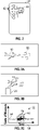
- FIGS. 3A-3G illustrate the one or more processors 44 of the portable electronic device 20 determining the insight event and transmitting the flight data associated with the insight event to either the one or more central computers 22 (seen in FIG. 3E ) or to one or more portable electronic devices 20 that are part of the local area network 30 (seen in FIG. 3F ).
- the insight event is the corresponding aircraft 10 undergoing turbulence, however, it is to be appreciated that FIGS. 3A-3G are merely illustrative in nature and the insight event is not limited to turbulence.
- the corresponding aircraft 10 undergoes turbulence.
- turbulence is created by a jet stream 50.
- FIG. 3B the corresponding aircraft 10 experiences irregular motion while undergoing turbulence.
- the one or more processors 44 of the portable electronic device 20 monitor the plurality of sensors 42 (seen in FIG. 2 ) for one or more parameters.
- the one or more parameters are measured by the one or more of plurality of sensors 42.
- the one or more parameters include acceleration forces and a rate of rotation about an axis.
- FIG. 3C shows a graph 52 illustrating a plot 54 representing the one or more parameters measured over time, where an x-axis of the graph 52 represents time and a y-axis represents units of measure.
- the plot 54 measures a turbulence event 56.
- the one or more processors 44 of the portable electronic device 20 compare the plot 54 representing one or more parameters over time with a predetermined trend 60 representing a change in value of the one or more parameters, where the predetermined trend 60 signifies the insight event is presently occurring.
- the one or more processors 44 of the individual portable electronic device 20 determine the one or more parameters follow the predetermined trend 60 based on a change in value of the one or more parameters, a duration of time as the one or more parameters change in value, and contextual information regarding operation of the corresponding aircraft 10.
- the predetermined trend 60 is illustrated as a plurality of trend lines 58, and the plot 54 follows an overall direction of the trend lines 58 during the turbulence event 56.
- the one or more processors 44 of the individual portable electronic device 20 determines the plot 54 follows the overall direction of the trend lines 58 based on the change in value of the plot 54, the duration of time as the plot 54 changes in value, and contextual information regarding operation of the corresponding aircraft 10. Specifically, as seen in FIG. 3C , the plot 54 increases and decreases in value in the same direction as the trend lines 58 of the predetermined trend 60. The plot 54 also includes a similar duration in time as the trend lines 58 of the predetermined trend 60.
- the contextual information regarding operation of the corresponding aircraft 10 includes information such as, but not limited to, phase of flight, aircraft position (coordinates and altitude), external data collected from aircraft avionics or other personal electronic devices, weather conditions, wind conditions, traffic conditions, and crew and passenger rosters.
- the contextual information includes the phase of flight because the corresponding aircraft 10 may experience a change in value of the acceleration forces and the rate of rotation about an axis for a duration of time that indicates the corresponding aircraft 10 is undergoing turbulence during the takeoff phase of flight.
- the change in value of the acceleration forces and the rate of rotation about an axis are created because the corresponding aircraft 10 is undergoing takeoff, and not because the corresponding aircraft 10 is undergoing turbulence.
- the corresponding aircraft 10 is not experiencing the insight event.
- the portable electronic device 20 determines the insight event is presently occurring upon the corresponding aircraft 10.
- the one or more processors 44 (seen in FIG. 2 ) of the portable electronic device 20 transmit the flight data associated with the insight event to the one or more central computers 22, which is shown in FIG. 3E .
- the one or more central computers 22 determine the overall flight data patterns based on the flight data associated with the insight event received from the portable electronic device 20.
- the one or more processors 44 of the portable electronic device 20 transmit the flight data associated with the insight event to one or more portable electronic devices 20 that are connected to the local area network 30, which is shown in FIG. 3F .
- the local area network 30 connects two or more portable electronic devices 20 that monitor flight data from separate aircraft 10.
- the individual portable electronic device 20A connected to the local area network 30 transmits the flight data associated with the insight event to one or more of remaining portable electronic devices 20B, 20C that are connected to the local area network 30.
- the flight data associated with the insight event includes a data packet 70.
- FIG. 3D the flight data associated with the insight event includes a data packet 70.
- the data packet 70 includes one or more of the following: a time 72 when the insight event occurred, a location 74 where the insight event occurred, a phase of flight 76 when the insight event occurred, the specific type of insight event 78, and one or more raw data samples 80, however, the data packet 70 may include other or different data as well.
- the time 72 is 12:47:32 in Coordinated Universal Time (UTC)
- the location is expressed in latitude and longitude
- the phase of flight is cruise
- the specific type of insight event 78 is a moderate turbulence event.
- the one or more central computers 22 determine overall flight data patterns based on the flight data associated with the insight event received from the portable electronic device 20 and the historical data stored in the one or more databases 32. In other words, the one or more central computers 22 determine trends and patterns that occur based on the insight event received from the portable electronic device 20 in addition to the historical data stored in the one or more databases 32 over a period of time to determine the overall flight data patterns.
- the historical data stored in the one or more databases 32 represents previously collected flight data associated with insight events that occurred upon the plurality of aircraft 10 ( FIG. 1 ).
- the historical data is collected over a period of time such as, for example, several minutes, days, weeks, months, or years.
- the historical data may include turbulence events collected over several days or weeks from various aircraft 10 that have traveled throughout a specific geographical region.
- the insight event is turbulence and the overall flight data pattern is a turbulence map 82.
- the turbulence map 82 indicates areas 84 in a geographic region 86 where turbulence has been experienced by one or more of the plurality of aircraft 10 ( FIG. 1 ).
- FIG. 3F illustrates the geographic region 86 as North America, it is to be appreciated that any geographic region may be used to create the turbulence map 82.
- the turbulence map 82 is determined based on trends or patterns that occur with respect to turbulence that the plurality of aircraft 10 experience over time.
- the overall flight data pattern indicates locations and dates and times where taxiways at a specific airport experience heightened congested. For example, the one or more central computers 22 may determine that the taxiways at the Heathrow airport located in London, England experience the most congestion on a Friday afternoon when compared to other times of the day or the week.
- the insight event is runway conditions
- the overall flight data pattern indicates various factors that may affect an aircraft during takeoff and landing such as, but not limited to, precipitation on the ground (i.e., water, snow, or ice), cracks and bumps on the runway surface, the length of the runway, and observed approach patterns.
- the flight data associated with the insight event is collected based on a particular airline fleet, a common manufacturer, or by a specific insight event.
- the plurality of aircraft 10 are part of the same airline fleet, and the one or more central computers 22 determine the overall flight patterns based on the flight data collected from the particular airline fleet.
- the overall flight patterns of the aircraft fleet are further determined based on aircraft type, route, time of year, and the like.
- the plurality of aircraft 10 are each produced by a common manufacturer.
- the overall flight patterns of the common manufacturer are further determined based on selected airlines, geographic region, aircraft type, and the like.
- a selected airline may choose to opt in and have the flight data collected and analyzed by the common manufacturer.
- the one or more central computers 22 determine the overall flight patterns based on the flight data collected from multiple airlines based on a specific insight event. For example, the one or more central computers 22 may determine the overall flight patterns based on the flight data associated with the corresponding aircraft 10 undergoing turbulence across multiple airlines.
- FIG. 4 is a process flow diagram illustrating a method 200 for aggregating flight data based on the one or more portable electronic devices 20.
- the method 200 may begin at block 202.
- an individual portable electronic device 20 monitors flight data from the corresponding aircraft 10.
- the plurality of sensors 42 (seen in FIG. 2 ) monitor the flight data from the corresponding aircraft 10.
- the method 200 may then proceed to block 204.
- the individual portable electronic device 20 determines the insight event indicating the incident of significance is presently occurring upon the corresponding aircraft 10.
- a method 300 for determining the insight event is shown in FIG. 5 and is described below. The method 200 may then proceed to block 206.
- the individual portable electronic device 20 transmits the flight data collected during the insight event to the one or more central computers 22.
- the method 200 may then proceed to block 208.
- the one or more central computers 22 receives the flight data collected during the insight event from the individual portable electronic device 20. The method 200 may then proceed to block 210.
- the one or more central computers 22 determine overall flight data patterns based on the flight data collected during the insight event received from the individual portable electronic device 20 and historical data stored in one or more databases 32. The method 200 may then proceed to block 212.
- Block 212 is optional and is therefore illustrated in phantom line.
- the individual portable electronic device 20 is part of a group of the portable electronic devices 20 that are in electronic communication with one another by the local area network 30, which is shown in FIG. 1 .
- the individual portable electronic device 20A sends the insight event to one or more remaining portable electronic devices 20B, 20C that are connected to the local area network 30. The method 200 5ay then terminate.
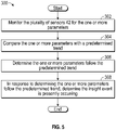
- the method 300 begins at block 302.
- the one or more processors 44 ( FIG. 2 ) of the individual portable electronic device 20 monitors the plurality of sensors 42 for the one or more parameters. The method 300 may then proceed to block 304.
- the individual portable electronic device 20 compares the one or more parameters with the predetermined trend 60 (seen in FIG. 3C ) representing a change in value of the one or more parameters.
- the predetermined trend signifies the insight event is presently occurring. The method 300 may then proceed to block 306.
- the individual portable electronic device 20 determines the one or more parameters follow the predetermined trend 60. The method 300 may then proceed to block 308.
- the individual portable electronic device 20 determines the insight event is presently occurring upon the corresponding aircraft 10. The method may then terminate.
- the disclosed flight data aggregation system includes various technical effects and benefits.
- the flight data aggregation system employs sensors that are part of a portable electronic device.
- the portable electronic device operates independently of the aircraft to collect data instead of relying upon pilot reports or other existing technologies to collect data.
- the flight data aggregation system leverages the computing power of the portable electronic devices to analyze the flight data.
- the portable electronic devices analyze the data in real-time, which may not be possible with existing systems. Accordingly, the disclosed flight data system provides a relatively fast, inexpensive, and accurate approach for globally analyzing flight data across multiple aircraft.
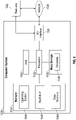
- the one or more central computers 22 are implemented on one or more computer devices or systems, such as illustrative computer system 1030.
- the computer system 1030 includes a processor 1032, a memory 1034, a mass storage memory device 1036, an input/output (I/O) interface 1038, and a Human Machine Interface (HMI) 1040.
- the computer system 1030 is operatively coupled to one or more external resources 1042 via the network 1026 or I/O interface 1038.
- External resources may include, but are not limited to, servers, databases, mass storage devices, peripheral devices, cloud-based network services, or any other suitable computer resource that may be used by the computer system 1030.
- the processor 1032 includes one or more devices selected from microprocessors, micro-controllers, digital signal processors, microcomputers, central processing units, field programmable gate arrays, programmable logic devices, state machines, logic circuits, analog circuits, digital circuits, or any other devices that manipulate signals (analog or digital) based on operational instructions that are stored in the memory 1034.
- Memory 1034 includes a single memory device or a plurality of memory devices including, but not limited to, read-only memory (ROM), random access memory (RAM), volatile memory, non-volatile memory, static random-access memory (SRAM), dynamic random-access memory (DRAM), flash memory, cache memory, or any other device capable of storing information.
- the mass storage memory device 1036 includes data storage devices such as a hard drive, optical drive, tape drive, volatile or non-volatile solid-state device, or any other device capable of storing information.
- the processor 1032 operates under the control of an operating system 1046 that resides in memory 1034.
- the operating system 1046 manages computer resources so that computer program code embodied as one or more computer software applications, such as an application 1048 residing in memory 1034, may have instructions executed by the processor 1032.
- the processor 1032 may execute the application 1048 directly, in which case the operating system 1046 may be omitted.
- One or more data structures 1049 also reside in memory 1034, and may be used by the processor 1032, operating system 1046, or application 1048 to store or manipulate data.
- the I/O interface 1038 provides a machine interface that operatively couples the processor 1032 to other devices and systems, such as the network 1026 or external resource 1042.
- the application 1048 thereby works cooperatively with the network 1026 or external resource 1042 by communicating via the I/O interface 1038 to provide the various features, functions, applications, processes, or modules comprising examples of the disclosure.
- the application 1048 also includes program code that is executed by one or more external resources 1042, or otherwise rely on functions or signals provided by other system or network components external to the computer system 1030.
- examples of the disclosure may include applications that are located externally to the computer system 1030, distributed among multiple computers or other external resources 1042, or provided by computing resources (hardware and software) that are provided as a service over the network 1026, such as a cloud computing service.
- the HMI 1040 is operatively coupled to the processor 1032 of computer system 1030 in a known manner to allow a user to interact directly with the computer system 1030.
- the HMI 1040 may include video or alphanumeric displays, a touch screen, a speaker, and any other suitable audio and visual indicators capable of providing data to the user.
- the HMI 1040 also includes input devices and controls such as an alphanumeric keyboard, a pointing device, keypads, pushbuttons, control knobs, microphones, etc., capable of accepting commands or input from the user and transmitting the entered input to the processor 1032.
- a database 1044 may reside on the mass storage memory device 1036 and may be used to collect and organize data used by the various systems and modules described herein.
- the database 1044 may include data and supporting data structures that store and organize the data.
- the database 1044 may be arranged with any database organization or structure including, but not limited to, a relational database, a hierarchical database, a network database, or combinations thereof.
- a database management system in the form of a computer software application executing as instructions on the processor 1032 may be used to access the information or data stored in records of the database 1044 in response to a query, where a query may be dynamically determined and executed by the operating system 1046, other applications 1048, or one or more modules.
Landscapes
- Engineering & Computer Science (AREA)
- Physics & Mathematics (AREA)
- Aviation & Aerospace Engineering (AREA)
- General Physics & Mathematics (AREA)
- Computer Networks & Wireless Communication (AREA)
- Radar, Positioning & Navigation (AREA)
- Electromagnetism (AREA)
- Remote Sensing (AREA)
- Health & Medical Sciences (AREA)
- Computing Systems (AREA)
- General Health & Medical Sciences (AREA)
- Medical Informatics (AREA)
- Signal Processing (AREA)
- Traffic Control Systems (AREA)
- Mobile Radio Communication Systems (AREA)
Abstract
Description
- The present disclosure relates to a flight data aggregation system and method. More particularly, the present disclosure is directed towards a flight data aggregation system for a plurality of aircraft, where the flight data is monitored and analyzed by one or more portable electronic devices.
- Gathering and aggregating large amounts of flight data is often a complicated, expensive, and time-consuming process. Some examples of technologies that focus on aggregating flight data include, but are not limited to, automatic dependent surveillance-broadcast (ADS-B) feeds, reporting databases such as the Aviation Safety Reporting System (ASRS), and regulatory initiatives such as the European aeronautical information services database (EAD) and the International Civil Aviation Organization (ICAO) databases.
- Existing technologies for aggregating flight data may lack the ability to gather and process the flight data in real-time. For example, legacy systems such as the Aircraft Communications Addressing and Reporting System (ACARS) may be employed to gather and share flight data. However, ACARS may be slow and relatively expensive. Newer approaches may utilize faster, more ubiquitous data feeds such as ADS-B. However, this approach provides only limited data parameters and insight for analysis. Therefore, there is a desire for an improved system and method for efficiently gathering and aggregating flight data.
- According to several aspects, a flight data aggregation system for a plurality of aircraft is disclosed. The flight data aggregation system includes one or more portable electronic devices that each monitor flight data from a corresponding aircraft. The one or more portable electronic devices analyze the flight data in real-time to determine that an insight event indicating an incident of significance is presently occurring upon the corresponding aircraft. The flight data aggregation system also includes one or more central computers in electronic communication with at least one of the one or more portable electronic devices. Each central computer includes one or more processors and a memory coupled to the one or more processors. The memory stores data into one or more databases and program code that, when executed by the one or more processors, causes the one or more central computers to receive flight data collected during an insight event from an individual portable electronic device. The one or more central computers also determine one or more overall flight data patterns based on the flight data collected during the insight event received from the individual portable electronic device and historical data stored in the one or more databases. The historical data represents previously collected flight data associated with insight events that occurred upon the plurality of aircraft.
- In another aspect, a flight data aggregation system for a plurality of aircraft is disclosed. The flight data aggregation system includes one or more portable electronic devices that each monitor flight data from one of the plurality of aircraft. The one or more portable electronic devices include a plurality of sensors that monitor the flight data associated with one of the plurality of aircraft. An individual portable electronic device is configured to analyze the flight data in real-time to determine that an insight event indicating an incident of significance is presently occurring upon a corresponding aircraft. In response to determining that the insight event is presently occurring, the individual portable electronic device transmits the flight data associated with the insight event. The flight data aggregation system also includes one or more central computers in electronic communication with the individual portable electronic device. Each central computer includes one or more processors and a memory coupled to the one or more processors. The memory stores data into one or more databases and program code that, when executed by the one or more processors, causes each of the one or more central computers to receive flight data associated with the insight event from an individual portable electronic device. The one or more central computers also determine one or more overall flight data patterns based on the flight data associated with the insight event received from the portable electronic device and historical data stored in the one or more databases. The historical data represents previously collected flight data associated with insight events that occurred upon the plurality of aircraft.
- In yet another aspect, a method for aggregating flight data for a plurality of aircraft by one or more portable electronic devices is disclosed. The method includes monitoring, by an individual portable electronic device, flight data from a corresponding aircraft, where the one or more portable electronic devices each include a plurality of sensors that monitor the flight data from the corresponding aircraft. The method also includes determining, by the individual portable electronic device, an insight event indicating an incident of significance is presently occurring upon the corresponding aircraft. The insight event indicates an incident of significance is presently occurring upon the corresponding aircraft. The method includes transmitting, by the individual portable electronic device, the flight data collected during the insight event to one or more central computers. The method also includes receiving, by the one or more central computers, the flight data collected during the insight event from the individual portable electronic device. Finally, the method includes determining, by the one or more central computers, one or more overall flight data patterns based on the flight data collected during the insight event based on the insight event received from the portable electronic device and historical data stored in one or more databases. The historical data represents previously collected flight data associated with insight events that occurred upon the plurality of aircraft.
- The features, functions, and advantages that have been discussed may be achieved independently in various aspects or may be combined in other aspects further details of which can be seen with reference to the following description and drawings.
- The drawings described herein are for illustration purposes only and are not intended to limit the scope of the present disclosure in any way.
-
FIG. 1 is schematic diagram illustrating the disclosed flight data aggregation system including a plurality of aircraft and one or more portable electronic devices, according to an illustrative aspect; -
FIG. 2 is a schematic diagram illustrating one of the portable electronic devices shown inFIG. 1 , according to an illustrative aspect; -
FIGS. 3A-3G illustrate the portable electronic device determining an insight event that is presently occurring onboard a corresponding aircraft, according to an illustrative aspect; -
FIG. 4 is a process flow diagram illustrating a method for aggregating flight data based on the one or more portable electronic devices, according to an illustrative aspect; -
FIG. 5 is a process flow diagram illustrating a method for determining the insight event, according to an illustrative aspect; and -
FIG. 6 illustrates an illustrative computer system for the disclosed system, according to an illustrative aspect. - The present disclosure is directed towards a flight data aggregation system for a plurality of aircraft, where the flight data is monitored and analyzed by one or more portable electronic devices that operate independently from the aircraft. The one or more portable electronic devices each include a plurality of sensors that monitor the flight data from a corresponding aircraft in real-time. Each individual portable electronic device analyzes the flight data to determine whether an insight event is presently occurring. The insight event indicates an incident of significance is presently occurring upon the corresponding aircraft. In response to determining that an insight event is presently occurring, the individual portable electronic device transmits the flight data collected during the insight event to one or more central computers. The one or more central computers determine overall flight data patterns based on the flight data collected during the insight event in combination with historical data. The historical data represents previously collected flight data associated with insight events that occurred upon the plurality of aircraft that is saved in one or more databases of the central computers. Thus, the flight data aggregation system leverages the computing power of the portable electronic devices to analyze the flight data, thereby alleviating the need to process the flight data by the one or more central computers.
- The following description is merely illustrative in nature and is not intended to limit the present disclosure, application, or uses.
- Referring to
FIG. 1 , a flightdata aggregation system 8 for a plurality ofaircraft 10 is illustrated. The flightdata aggregation system 8 includes one or more portableelectronic devices 20 and one or morecentral computers 22. In the aspect as shown inFIG. 1 , the flightdata aggregation system 8 includes a plurality of portableelectronic devices 20, where each portableelectronic device 20 monitors flight data from acorresponding aircraft 10. AlthoughFIG. 1 illustrates a single portableelectronic device 20 associated with eachaircraft 10, it is to be appreciated thatFIG. 1 is merely illustrative in nature and more than one portableelectronic device 20 may be associated with eachaircraft 10 as well. The plurality ofaircraft 10 are in flight or are located on theground 28. The one or morecentral computers 22 are in electronic communication with the one or morecentral computers 22 using any type of wireless communication protocol. For example, if theaircraft 10 is in flight, the wireless communication protocol may be the Aircraft Communications Addressing and Reporting System (ACARS), and if theaircraft 10 is located onground 28 the wireless communication protocol may be a fifth generation (5G) broadband cellular network system. - As explained below, the portable
electronic devices 20 monitor and analyze flight data from a correspondingaircraft 10 in real-time. Accordingly, the flightdata aggregation system 8 leverages the computing power of the portableelectronic devices 20 to analyze the flight data, which in turn alleviates the need to process the flight data by the one or morecentral computers 22 in real-time. Specifically, each portableelectronic device 20 analyzes the flight data to determine or identify an insight event. The insight event indicates an incident of significance is presently occurring upon the correspondingaircraft 10. One example of an insight event is the correspondingaircraft 10 undergoing turbulence. In this example, the portableelectronic device 20 monitors data collected by a gyroscope and an accelerometer to determine the correspondingaircraft 10 is presently undergoing turbulence. In response to determining the insight event, the portableelectronic device 20 transmits the flight data collected during the insight event to the one or morecentral computers 22. The one or morecentral computers 22 store historical data in one ormore databases 32, where the historical data represents previously collected flight data associated with insight events that occurred upon the plurality ofaircraft 10. The one or morecentral computers 22 determine overall flight data patterns based on the flight data associated with the insight event received from the portableelectronic device 20 and the historical data stored in the one or more databases. For example, if the insight event is the correspondingaircraft 10 undergoing turbulence, then the overall flight data pattern is a turbulence map. In some aspects, two or more portableelectronic devices 20 that monitor flight data fromseparate aircraft 10 are in electronic communication with one another by alocal area network 30. In the example as shown inFIG. 1 , three portableelectronic devices aircraft electronic devices local area network 30 transmit the flight data associated with the insight event to one or more of the remaining portableelectronic devices local area network 30. For example, if the portableelectronic device 20A determines an insight event, the remaining portableelectronic devices aircraft aircraft 10A. - In the aspect as shown in
FIG. 1 , twocentral computers 22 are located on theground 28. However, it is to be appreciated that this illustration is illustrative in nature and the flightdata aggregation system 8 may include any number ofcentral computers 22. Furthermore, althoughFIG. 1 illustrates the one or morecentral computers 22 on theground 28, in another aspect the one or morecentral computers 22 may be located upon one of theaircraft 10. - The one or more portable
electronic devices 20 include any type of electronic device configured to monitor, analyze, and transmit flight data from a correspondingaircraft 10 to the one or morecentral computers 22. Some examples of portableelectronic devices 20 include, but are not limited to, laptop computers, tablet computers, and smartphones. It is to be appreciated that the one or more portableelectronic devices 20 are not associated with operation of the correspondingaircraft 10, where operation of the aircraft involves manipulating the flight control systems. In other words, the one or more portableelectronic devices 20 are independent with respect to operating the correspondingaircraft 10. - The portable
electronic devices 20 may be located onboard the correspondingaircraft 10 or, in the alternative, outside of the correspondingaircraft 10. For example, in one aspect, the individual portableelectronic device 20 may be utilized by the cabin crew of the correspondingaircraft 10 or mounted to a wall of the correspondingaircraft 10. In yet another aspect, the portableelectronic device 20 is the electronic flight bag associated with the correspondingaircraft 10. In another aspect, the individual portableelectronic device 20 is utilized by a passenger onboard the correspondingaircraft 10, where the passenger has granted access to his or her portableelectronic device 20. In the alternative, the portableelectronic device 20 is used by an individual located outside of the correspondingaircraft 10. -
FIG. 2 is a schematic diagram illustrating one of the portableelectronic devices 20. Each portableelectronic device 20 includes a plurality ofsensors 42 configured to monitor the flight data associated with the correspondingaircraft 10. The plurality ofsensors 42 are in electronic communication with one ormore processors 44 of the portableelectronic device 20. In one non-limiting aspect, the plurality ofsensors 42 include one or more of the following: a magnetometer, a gyroscope, an accelerometer, a barometer, a microphone, a global positioning system (GPS), a biometric sensor, an air quality sensor, a humidity sensor, an ambient temperature sensor, an infrared sensor, and a light detection and ranging (LiDAR) sensor, however, it is to be appreciated that the portableelectronic devices 20 may include other types of sensors may be used as well. - The one or
more processors 44 of each portableelectronic device 20 monitor the flight data collected by the plurality ofsensors 42 and analyze the flight data to determine that the insight event indicating the incident of significance presently occurring upon the correspondingaircraft 10. The insight event includes any type of incident occurring upon the correspondingaircraft 10 that creates a change in one or more parameters, where the one or more parameters are measured by the plurality ofsensors 42 of each portableelectronic device 20. As mentioned above, one example of the insight event is when the correspondingaircraft 10 undergoes turbulence. In the present example, the change in one or more parameters created by turbulence include acceleration forces, which are measured by accelerometers, and a rate of rotation about an axis, which is measured by gyroscopes. In addition to turbulence, some examples of the insight event include, but are not limited to, landing distance, out, off, on and in (OOOI) times, takeoff distance, phase of flight, a congested taxiway, flight level change, holding, height loss during the climb phase of flight, lavatory use, de-icing or anti-icing status, runway surface conditions,, GPS spoofing or jamming events, and crew punctuality and location tracking. -
FIGS. 3A-3G illustrate the one ormore processors 44 of the portableelectronic device 20 determining the insight event and transmitting the flight data associated with the insight event to either the one or more central computers 22 (seen inFIG. 3E ) or to one or more portableelectronic devices 20 that are part of the local area network 30 (seen inFIG. 3F ). In the aspect as described and as shown inFIGS. 3A-3G , the insight event is the correspondingaircraft 10 undergoing turbulence, however, it is to be appreciated thatFIGS. 3A-3G are merely illustrative in nature and the insight event is not limited to turbulence. - Referring now to
FIG. 3A , the correspondingaircraft 10 undergoes turbulence. In the example as shown inFIG. 3A , turbulence is created by ajet stream 50. Referring now toFIG. 3B , the correspondingaircraft 10 experiences irregular motion while undergoing turbulence. As the correspondingaircraft 10 undergoes turbulence, the one ormore processors 44 of the portableelectronic device 20 monitor the plurality of sensors 42 (seen inFIG. 2 ) for one or more parameters. The one or more parameters are measured by the one or more of plurality ofsensors 42. In the present example, the one or more parameters include acceleration forces and a rate of rotation about an axis. -
FIG. 3C shows agraph 52 illustrating aplot 54 representing the one or more parameters measured over time, where an x-axis of thegraph 52 represents time and a y-axis represents units of measure. In the aspect as shown inFIG. 3C , theplot 54 measures a turbulence event 56. Referring to bothFIGS. 2 and 3A , the one ormore processors 44 of the portableelectronic device 20 compare theplot 54 representing one or more parameters over time with apredetermined trend 60 representing a change in value of the one or more parameters, where thepredetermined trend 60 signifies the insight event is presently occurring. - The one or
more processors 44 of the individual portableelectronic device 20 determine the one or more parameters follow thepredetermined trend 60 based on a change in value of the one or more parameters, a duration of time as the one or more parameters change in value, and contextual information regarding operation of the correspondingaircraft 10. In the example as shown inFIG. 3C , thepredetermined trend 60 is illustrated as a plurality oftrend lines 58, and theplot 54 follows an overall direction of thetrend lines 58 during the turbulence event 56. Accordingly, since theplot 54 represents the one or more parameters, the one ormore processors 44 of the individual portableelectronic device 20 determines theplot 54 follows the overall direction of thetrend lines 58 based on the change in value of theplot 54, the duration of time as theplot 54 changes in value, and contextual information regarding operation of the correspondingaircraft 10. Specifically, as seen inFIG. 3C , theplot 54 increases and decreases in value in the same direction as thetrend lines 58 of thepredetermined trend 60. Theplot 54 also includes a similar duration in time as thetrend lines 58 of thepredetermined trend 60. - The contextual information regarding operation of the corresponding
aircraft 10 includes information such as, but not limited to, phase of flight, aircraft position (coordinates and altitude), external data collected from aircraft avionics or other personal electronic devices, weather conditions, wind conditions, traffic conditions, and crew and passenger rosters. In the present example, the contextual information includes the phase of flight because the correspondingaircraft 10 may experience a change in value of the acceleration forces and the rate of rotation about an axis for a duration of time that indicates the correspondingaircraft 10 is undergoing turbulence during the takeoff phase of flight. However, the change in value of the acceleration forces and the rate of rotation about an axis are created because the correspondingaircraft 10 is undergoing takeoff, and not because the correspondingaircraft 10 is undergoing turbulence. Thus, the correspondingaircraft 10 is not experiencing the insight event. - In response to determining the one or more parameters follow the
predetermined trend 60, the portableelectronic device 20 determines the insight event is presently occurring upon the correspondingaircraft 10. In response to determining the insight event is presently occurring, the one or more processors 44 (seen inFIG. 2 ) of the portableelectronic device 20 transmit the flight data associated with the insight event to the one or morecentral computers 22, which is shown inFIG. 3E . As explained below, the one or morecentral computers 22 determine the overall flight data patterns based on the flight data associated with the insight event received from the portableelectronic device 20. - In addition to or in the alternative, the one or
more processors 44 of the portableelectronic device 20 transmit the flight data associated with the insight event to one or more portableelectronic devices 20 that are connected to thelocal area network 30, which is shown inFIG. 3F . Thelocal area network 30 connects two or more portableelectronic devices 20 that monitor flight data fromseparate aircraft 10. For example, in the aspect as shown inFIG. 3F , the individual portableelectronic device 20A connected to thelocal area network 30 transmits the flight data associated with the insight event to one or more of remaining portableelectronic devices local area network 30. Referring now toFIG. 3D , the flight data associated with the insight event includes adata packet 70. In the aspect as shown inFIG. 3D , thedata packet 70 includes one or more of the following: atime 72 when the insight event occurred, alocation 74 where the insight event occurred, a phase offlight 76 when the insight event occurred, the specific type ofinsight event 78, and one or moreraw data samples 80, however, thedata packet 70 may include other or different data as well. In the example as shown, thetime 72 is 12:47:32 in Coordinated Universal Time (UTC), the location is expressed in latitude and longitude, the phase of flight is cruise, and the specific type ofinsight event 78 is a moderate turbulence event. - Referring now to
FIGS. 1 and3F , the one or morecentral computers 22 determine overall flight data patterns based on the flight data associated with the insight event received from the portableelectronic device 20 and the historical data stored in the one ormore databases 32. In other words, the one or morecentral computers 22 determine trends and patterns that occur based on the insight event received from the portableelectronic device 20 in addition to the historical data stored in the one ormore databases 32 over a period of time to determine the overall flight data patterns. The historical data stored in the one ormore databases 32 represents previously collected flight data associated with insight events that occurred upon the plurality of aircraft 10 (FIG. 1 ). The historical data is collected over a period of time such as, for example, several minutes, days, weeks, months, or years. For example, the historical data may include turbulence events collected over several days or weeks fromvarious aircraft 10 that have traveled throughout a specific geographical region. - In the example as shown in
FIG. 3F , the insight event is turbulence and the overall flight data pattern is aturbulence map 82. Theturbulence map 82 indicatesareas 84 in ageographic region 86 where turbulence has been experienced by one or more of the plurality of aircraft 10 (FIG. 1 ). AlthoughFIG. 3F illustrates thegeographic region 86 as North America, it is to be appreciated that any geographic region may be used to create theturbulence map 82. Theturbulence map 82 is determined based on trends or patterns that occur with respect to turbulence that the plurality ofaircraft 10 experience over time. In another example, if the insight event is a congested taxiway, then the overall flight data pattern indicates locations and dates and times where taxiways at a specific airport experience heightened congested. For example, the one or morecentral computers 22 may determine that the taxiways at the Heathrow airport located in London, England experience the most congestion on a Friday afternoon when compared to other times of the day or the week. In yet another example, if the insight event is runway conditions, then the overall flight data pattern indicates various factors that may affect an aircraft during takeoff and landing such as, but not limited to, precipitation on the ground (i.e., water, snow, or ice), cracks and bumps on the runway surface, the length of the runway, and observed approach patterns. - Referring back to
FIG. 1 , in one aspect, the flight data associated with the insight event is collected based on a particular airline fleet, a common manufacturer, or by a specific insight event. Specifically, in one aspect, the plurality ofaircraft 10 are part of the same airline fleet, and the one or morecentral computers 22 determine the overall flight patterns based on the flight data collected from the particular airline fleet. In one example, the overall flight patterns of the aircraft fleet are further determined based on aircraft type, route, time of year, and the like. In another aspect, the plurality ofaircraft 10 are each produced by a common manufacturer. The overall flight patterns of the common manufacturer are further determined based on selected airlines, geographic region, aircraft type, and the like. Specifically, a selected airline may choose to opt in and have the flight data collected and analyzed by the common manufacturer. In still another aspect, the one or morecentral computers 22 determine the overall flight patterns based on the flight data collected from multiple airlines based on a specific insight event. For example, the one or morecentral computers 22 may determine the overall flight patterns based on the flight data associated with the correspondingaircraft 10 undergoing turbulence across multiple airlines. -
FIG. 4 is a process flow diagram illustrating amethod 200 for aggregating flight data based on the one or more portableelectronic devices 20. Referring now toFIGS. 1 ,2 , and4 , themethod 200 may begin atblock 202. Inblock 202, an individual portableelectronic device 20 monitors flight data from the correspondingaircraft 10. As mentioned above, the plurality of sensors 42 (seen inFIG. 2 ) monitor the flight data from the correspondingaircraft 10. Themethod 200 may then proceed to block 204. - In
block 204, the individual portableelectronic device 20 determines the insight event indicating the incident of significance is presently occurring upon the correspondingaircraft 10. Amethod 300 for determining the insight event is shown inFIG. 5 and is described below. Themethod 200 may then proceed to block 206. - In
block 206, in response to determining the insight event is presently occurring, the individual portableelectronic device 20 transmits the flight data collected during the insight event to the one or morecentral computers 22. Themethod 200 may then proceed to block 208. - In
block 208, the one or morecentral computers 22 receives the flight data collected during the insight event from the individual portableelectronic device 20. Themethod 200 may then proceed to block 210. - In
block 210, the one or morecentral computers 22 determine overall flight data patterns based on the flight data collected during the insight event received from the individual portableelectronic device 20 and historical data stored in one ormore databases 32. Themethod 200 may then proceed to block 212. -
Block 212 is optional and is therefore illustrated in phantom line. Inblock 212, the individual portableelectronic device 20 is part of a group of the portableelectronic devices 20 that are in electronic communication with one another by thelocal area network 30, which is shown inFIG. 1 . Inblock 212, the individual portableelectronic device 20A sends the insight event to one or more remaining portableelectronic devices local area network 30. Themethod 200 5ay then terminate. - Referring now to
FIG. 5 , themethod 300 for determining the insight event is now described. Referring toFIGS. 1 ,2 ,3A-3G , and5 , themethod 300 begins atblock 302. Inblock 302, the one or more processors 44 (FIG. 2 ) of the individual portableelectronic device 20 monitors the plurality ofsensors 42 for the one or more parameters. Themethod 300 may then proceed to block 304. - In
block 304, the individual portableelectronic device 20 compares the one or more parameters with the predetermined trend 60 (seen inFIG. 3C ) representing a change in value of the one or more parameters. As mentioned above, the predetermined trend signifies the insight event is presently occurring. Themethod 300 may then proceed to block 306. - In
block 306, the individual portableelectronic device 20 determines the one or more parameters follow thepredetermined trend 60. Themethod 300 may then proceed to block 308. - In
block 308, in response to determining the one or more parameters follow thepredetermined trend 60, the individual portableelectronic device 20 determines the insight event is presently occurring upon the correspondingaircraft 10. The method may then terminate. - Referring generally to the figures, the disclosed flight data aggregation system includes various technical effects and benefits. Specifically, the flight data aggregation system employs sensors that are part of a portable electronic device. The portable electronic device operates independently of the aircraft to collect data instead of relying upon pilot reports or other existing technologies to collect data. Thus, the flight data aggregation system leverages the computing power of the portable electronic devices to analyze the flight data. Furthermore, the portable electronic devices analyze the data in real-time, which may not be possible with existing systems. Accordingly, the disclosed flight data system provides a relatively fast, inexpensive, and accurate approach for globally analyzing flight data across multiple aircraft.
- Referring to
FIG. 6 , the one or morecentral computers 22 are implemented on one or more computer devices or systems, such asillustrative computer system 1030. Thecomputer system 1030 includes aprocessor 1032, amemory 1034, a massstorage memory device 1036, an input/output (I/O)interface 1038, and a Human Machine Interface (HMI) 1040. Thecomputer system 1030 is operatively coupled to one or moreexternal resources 1042 via thenetwork 1026 or I/O interface 1038. External resources may include, but are not limited to, servers, databases, mass storage devices, peripheral devices, cloud-based network services, or any other suitable computer resource that may be used by thecomputer system 1030. - The
processor 1032 includes one or more devices selected from microprocessors, micro-controllers, digital signal processors, microcomputers, central processing units, field programmable gate arrays, programmable logic devices, state machines, logic circuits, analog circuits, digital circuits, or any other devices that manipulate signals (analog or digital) based on operational instructions that are stored in thememory 1034.Memory 1034 includes a single memory device or a plurality of memory devices including, but not limited to, read-only memory (ROM), random access memory (RAM), volatile memory, non-volatile memory, static random-access memory (SRAM), dynamic random-access memory (DRAM), flash memory, cache memory, or any other device capable of storing information. The massstorage memory device 1036 includes data storage devices such as a hard drive, optical drive, tape drive, volatile or non-volatile solid-state device, or any other device capable of storing information. - The
processor 1032 operates under the control of anoperating system 1046 that resides inmemory 1034. Theoperating system 1046 manages computer resources so that computer program code embodied as one or more computer software applications, such as anapplication 1048 residing inmemory 1034, may have instructions executed by theprocessor 1032. In an alternative example, theprocessor 1032 may execute theapplication 1048 directly, in which case theoperating system 1046 may be omitted. One ormore data structures 1049 also reside inmemory 1034, and may be used by theprocessor 1032,operating system 1046, orapplication 1048 to store or manipulate data. - The I/
O interface 1038 provides a machine interface that operatively couples theprocessor 1032 to other devices and systems, such as thenetwork 1026 orexternal resource 1042. Theapplication 1048 thereby works cooperatively with thenetwork 1026 orexternal resource 1042 by communicating via the I/O interface 1038 to provide the various features, functions, applications, processes, or modules comprising examples of the disclosure. Theapplication 1048 also includes program code that is executed by one or moreexternal resources 1042, or otherwise rely on functions or signals provided by other system or network components external to thecomputer system 1030. Indeed, given the nearly endless hardware and software configurations possible, persons having ordinary skill in the art will understand that examples of the disclosure may include applications that are located externally to thecomputer system 1030, distributed among multiple computers or otherexternal resources 1042, or provided by computing resources (hardware and software) that are provided as a service over thenetwork 1026, such as a cloud computing service. - The
HMI 1040 is operatively coupled to theprocessor 1032 ofcomputer system 1030 in a known manner to allow a user to interact directly with thecomputer system 1030. TheHMI 1040 may include video or alphanumeric displays, a touch screen, a speaker, and any other suitable audio and visual indicators capable of providing data to the user. TheHMI 1040 also includes input devices and controls such as an alphanumeric keyboard, a pointing device, keypads, pushbuttons, control knobs, microphones, etc., capable of accepting commands or input from the user and transmitting the entered input to theprocessor 1032. - A
database 1044 may reside on the massstorage memory device 1036 and may be used to collect and organize data used by the various systems and modules described herein. Thedatabase 1044 may include data and supporting data structures that store and organize the data. In particular, thedatabase 1044 may be arranged with any database organization or structure including, but not limited to, a relational database, a hierarchical database, a network database, or combinations thereof. A database management system in the form of a computer software application executing as instructions on theprocessor 1032 may be used to access the information or data stored in records of thedatabase 1044 in response to a query, where a query may be dynamically determined and executed by theoperating system 1046,other applications 1048, or one or more modules. - The disclosure comprises example aspects in accordance with the following Clauses:
- Clause 1. A flight data aggregation system for a plurality of aircraft, the flight data aggregation system comprising:
- one or more portable electronic devices that each monitor flight data from a corresponding aircraft, wherein the one or more portable electronic devices analyze the flight data in real-time to determine that an insight event indicating an incident of significance is presently occurring upon the corresponding aircraft; and
- one or more central computers in electronic communication with at least one of the one or more portable electronic devices, wherein each central computer includes one or more processors and a memory coupled to the one or more processors, the memory storing data into one or more databases and program code that, when executed by the one or more processors, causes the one or more central computers to:
- receive flight data collected during an insight event from an individual portable electronic device; and
- determine one or more overall flight data patterns based on the flight data collected during the insight event received from the individual portable electronic device and historical data stored in the one or more databases, wherein the historical data represents previously collected flight data associated with insight events that occurred upon the plurality of aircraft.
- Clause 2. The flight data aggregation system of Clause 1, wherein the one or more portable electronic devices each include a plurality of sensors that monitor the flight data from the corresponding aircraft.
- Clause 3. The flight data aggregation system of Clause 2, wherein the plurality of sensors includes at least one of the following: a magnetometer, a gyroscope, a barometer, a microphone, and a global positioning system (GPS).
- Clause 4. The flight data aggregation system of Clause 2 or 3, wherein the plurality of sensors includes at least one of the following: a biometric sensor, an air quality sensor, a humidity sensor, an ambient temperature sensor, an infrared sensor, and a light detection and ranging (LiDAR) sensor.
- Clause 5. The flight data aggregation system of any of Clauses 2-4, wherein the individual portable electronic device is caused to:
- monitor the plurality of sensors for one or more parameters;
- compare one or more parameters with a predetermined trend representing a change in value of the one or more parameters, wherein the predetermined trend signifies the insight event is presently occurring;
- determine the one or more parameters follow the predetermined trend; and
- in response to determining the one or more parameters follow the predetermined trend, determine the insight event is presently occurring upon the corresponding aircraft.
- Clause 6. The flight data aggregation system of Clause 5, wherein the individual portable electronic device is caused to:
in response to determining the insight event is presently occurring, transmit the flight data associated with the insight event to the one or more central computers. - Clause 7. The flight data aggregation system of Clause 5 or 6, wherein the individual portable electronic device determines the one or more parameters follows the predetermined trend based on a change in value of the one or more parameters, a duration of time as the one or more parameters change in value, and contextual information regarding operation of the corresponding aircraft.
-
Clause 8. The flight data aggregation system of any of Clauses 1-7, wherein the flight data associated with the insight event includes one or more of the following: a time when the insight event occurred, a location where the insight event occurred, a phase of flight when the insight event occurred, a specific type of insight event, and one or more raw data samples. - Clause 9. The flight data aggregation system of any of Clauses 1-8, wherein a group of the one or more portable electronic devices including the individual portable electronic device are in electronic communication with one another by a local area network.
-
Clause 10. The flight data aggregation system of Clause 9, wherein the individual portable electronic device sends the insight event to one or more remaining portable electronic devices connected to the local area network. - Clause 11. The flight data aggregation system of any of Clauses 1-10, wherein the individual portable electronic device is utilized by one of the following: a passenger onboard the corresponding aircraft, an individual located outside of the corresponding aircraft, or by a cabin crew of the corresponding aircraft.
- Clause 12. The flight data aggregation system of any of Clauses 1-11, wherein the insight event includes one of the following: turbulence, a congested taxiway, and runway conditions.
- Clause 13. The flight data aggregation system of any of Clauses 1-12, the flight data associated with the insight event is collected based on a particular airline fleet, a common manufacturer, or by a specific insight event.
- Clause 14. A flight data aggregation system for a plurality of aircraft, the flight data aggregation system comprising:
- one or more portable electronic devices that each monitor flight data from one of the plurality of aircraft, wherein the one or more portable electronic devices include a plurality of sensors that monitor the flight data associated with one of the plurality of aircraft, wherein an individual portable electronic device is configured to:
- analyze the flight data in real-time to determine that an insight event indicating an incident of significance is presently occurring upon a corresponding aircraft; and
- in response to determining that the insight event is presently occurring, transmit the flight data associated with the insight event;
- one or more central computers in electronic communication with the individual portable electronic device, wherein each central computer includes one or more processors and a memory coupled to the one or more processors, the memory storing data into one or more databases and program code that, when executed by the one or more processors, causes each of the one or more central computers to:
- receive flight data associated with the insight event from an individual portable electronic device; and
- determine one or more overall flight data patterns based on the flight data associated with the insight event received from the individual portable electronic device and historical data stored in the one or more databases, wherein the historical data represents previously collected flight data associated with insight events that occurred upon the plurality of aircraft.
- one or more portable electronic devices that each monitor flight data from one of the plurality of aircraft, wherein the one or more portable electronic devices include a plurality of sensors that monitor the flight data associated with one of the plurality of aircraft, wherein an individual portable electronic device is configured to:
- Clause 15. The flight data aggregation system of Clause 14, wherein the individual portable electronic device is caused to:
- monitor the plurality of sensors for one or more parameters;
- compare one or more parameters with a predetermined trend representing a change in value of the one or more parameters, wherein the predetermined trend signifies the insight event is presently occurring;
- determine the one or more parameters follow the predetermined trend; and
- in response to determining the one or more parameters follow the predetermined trend, determine the insight event is presently occurring upon the corresponding aircraft.
- Clause 16. A method for aggregating flight data for a plurality of aircraft by one or more portable electronic devices, the method comprising:
- monitoring, by an individual portable electronic device, flight data from a corresponding aircraft, wherein the one or more portable electronic devices each include a plurality of sensors that monitor the flight data from the corresponding aircraft;
- determining, by an individual portable electronic device, that an insight event indicating an incident of significance is presently occurring upon the corresponding aircraft, wherein the insight event indicates an incident of significance is presently occurring upon the corresponding aircraft;
- transmitting, by the individual portable electronic device, the flight data collected during the insight event to one or more central computers;
- receiving, by the one or more central computers, the flight data collected during the insight event from the individual portable electronic device; and
- determining, by the one or more central computers, one or more overall flight data patterns based on the flight data collected during the insight event and historical data stored in one or more databases, wherein the historical data represents previously collected flight data associated with insight events that occurred upon the plurality of aircraft.
- Clause 17. The method of Clause 16, wherein determining the insight event comprises:
- monitoring the plurality of sensors of the individual portable electronic device for one or more parameters;
- comparing, by the individual portable electronic device, one or more parameters with a predetermined trend representing a change in value of the one or more parameters, wherein the predetermined trend signifies the insight event is presently occurring;
- determining the one or more parameters follow the predetermined trend; and
- in response to determining the one or more parameters follow the predetermined trend, determining the insight event is presently occurring upon the corresponding aircraft.
- Clause 18. The method of Clause 17, further comprising:
determining the one or more parameters follow the predetermined trend based on a change in value of the one or more parameters, a duration of time as the one or more parameters change in value, and contextual information regarding operation of the corresponding aircraft. - Clause 19. The method of any of Clauses 16-18, wherein a group of portable electronic devices are in electronic communication with one another by a local area network, wherein the individual portable electronic device is part of the group of portable electronic devices.
-
Clause 20. The method of Clause 19, further comprising:
sending, by the individual portable electronic device, the insight event to one or more remaining portable electronic devices connected to the local area network. - The description of the present disclosure is merely illustrative in nature and variations that do not depart from the gist of the present disclosure are intended to be within the scope of the present disclosure. Such variations are not to be regarded as a departure from the scope of the present disclosure.
Claims (15)
- A flight data aggregation system (8) for a plurality of aircraft (10), the flight data aggregation system (8) comprising:one or more portable electronic devices (20) that each monitor flight data from a corresponding aircraft (10), wherein the one or more portable electronic devices (20) analyze the flight data in real-time to determine that an insight event indicating an incident of significance is presently occurring upon the corresponding aircraft (10); andone or more central computers (22) in electronic communication with at least one of the one or more portable electronic devices (20), wherein each central computer (22) includes one or more processors (1032) and a memory (1034) coupled to the one or more processors (1032), the memory (1034) storing data into one or more databases (32) and program code that, when executed by the one or more processors (1032), causes the one or more central computers (22) to:receive flight data collected during an insight event from an individual portable electronic device (20); anddetermine one or more overall flight data patterns based on the flight data collected during the insight event received from the individual portable electronic device (20) and historical data stored in the one or more databases (32), wherein the historical data represents previously collected flight data associated with insight events that occurred upon the plurality of aircraft (10).
- The flight data aggregation system (8) of claim 1, wherein the one or more portable electronic devices (20) each include a plurality of sensors (42) that monitor the flight data from the corresponding aircraft (10).
- The flight data aggregation system (8) of claim 2, wherein the plurality of sensors (42) includes at least one of the following: a magnetometer, a gyroscope, a barometer, a microphone, and a global positioning system (GPS).
- The flight data aggregation system (8) of claim 2 or 3, wherein the plurality of sensors (42) includes at least one of the following: a biometric sensor, an air quality sensor, a humidity sensor, an ambient temperature sensor, an infrared sensor, and a light detection and ranging (LiDAR) sensor.
- The flight data aggregation system (8) of any of claims 2-4, wherein the individual portable electronic device (20) is caused to:monitor the plurality of sensors (42) for one or more parameters;compare one or more parameters with a predetermined trend (60) representing a change in value of the one or more parameters, wherein the predetermined trend (60) signifies the insight event is presently occurring;determine the one or more parameters follow the predetermined trend (60); andin response to determining the one or more parameters follow the predetermined trend (60), determine the insight event is presently occurring upon the corresponding aircraft (10).
- The flight data aggregation system (8) of any of claims 1-5, wherein the flight data associated with the insight event includes one or more of the following: a time (72) when the insight event occurred, a location (74) where the insight event occurred, a phase of flight (76) when the insight event occurred, a specific type of insight event (78), and one or more raw data samples (80).
- The flight data aggregation system (8) of any of claims 1-6, wherein a group of the one or more portable electronic devices (20) including the individual portable electronic device (20) are in electronic communication with one another by a local area network (30).
- The flight data aggregation system (8) of any of claims 1-7, wherein the individual portable electronic device (20) is utilized by one of the following: a passenger onboard the corresponding aircraft (10), an individual located outside of the corresponding aircraft (10), or by a cabin crew of the corresponding aircraft (10).
- The flight data aggregation system (8) of any of claims 1-8, wherein the insight event includes one of the following: turbulence, a congested taxiway, and runway conditions.
- The flight data aggregation system (8) of any of claims 1-9, the flight data associated with the insight event is collected based on a particular airline fleet, a common manufacturer, or by a specific insight event.
- A method (200) for aggregating flight data for a plurality of aircraft (10) by one or more portable electronic devices (20), the method (200) comprising:monitoring, by an individual portable electronic device (20), flight data from a corresponding aircraft (100), wherein the one or more portable electronic devices (20) each include a plurality of sensors (42) that monitor the flight data from the corresponding aircraft (10);determining, by an individual portable electronic device (20), that an insight event indicating an incident of significance is presently occurring upon the corresponding aircraft, wherein the insight event indicates an incident of significance is presently occurring upon the corresponding aircraft (10);transmitting, by the individual portable electronic device (20), the flight data collected during the insight event to one or more central computers (22);receiving, by the one or more central computers (22), the flight data collected during the insight event from the individual portable electronic device (20); anddetermining, by the one or more central computers (22), one or more overall flight data patterns based on the flight data collected during the insight event and historical data stored in one or more databases (32), wherein the historical data represents previously collected flight data associated with insight events that occurred upon the plurality of aircraft (10).
- The method (200) of claim 11, wherein determining the insight event comprises:monitoring the plurality of sensors (42) of the individual portable electronic device (20) for one or more parameters;comparing, by the individual portable electronic device (20), one or more parameters with a predetermined trend (60) representing a change in value of the one or more parameters, wherein the predetermined trend (60) signifies the insight event is presently occurring;determining the one or more parameters follow the predetermined trend (60); andin response to determining the one or more parameters follow the predetermined trend (60), determining the insight event is presently occurring upon the corresponding aircraft (10).
- The method (200) of claim 12, further comprising:
determining the one or more parameters follow the predetermined trend (60) based on a change in value of the one or more parameters, a duration of time as the one or more parameters change in value, and contextual information regarding operation of the corresponding aircraft (10). - The method (200) of any of claims 11-13, wherein a group of portable electronic devices (20A, 20B, 20C) are in electronic communication with one another by a local area network (30), wherein the individual portable electronic device (20A) is part of the group of portable electronic devices (20A, 20B, 20C).
- The method (200) of claim 14, further comprising:
sending, by the individual portable electronic device (20A), the insight event to one or more remaining portable electronic devices (20B, 20C) connected to the local area network (30).
Applications Claiming Priority (1)
| Application Number | Priority Date | Filing Date | Title |
|---|---|---|---|
| US17/375,230 US11955015B2 (en) | 2021-07-14 | 2021-07-14 | Flight data aggregation system including portable electronic devices |
Publications (1)
| Publication Number | Publication Date |
|---|---|
| EP4120221A1 true EP4120221A1 (en) | 2023-01-18 |
Family
ID=80978931
Family Applications (1)
| Application Number | Title | Priority Date | Filing Date |
|---|---|---|---|
| EP22164876.9A Pending EP4120221A1 (en) | 2021-07-14 | 2022-03-28 | Flight data aggregation system including portable electronic devices |
Country Status (3)
| Country | Link |
|---|---|
| US (1) | US11955015B2 (en) |
| EP (1) | EP4120221A1 (en) |
| CN (1) | CN115620419A (en) |
Families Citing this family (5)
| Publication number | Priority date | Publication date | Assignee | Title |
|---|---|---|---|---|
| US12248077B2 (en) * | 2021-12-23 | 2025-03-11 | Rockwell Collins, Inc. | System and method for airborne GNSS RF interference detection |
| US20240412643A1 (en) * | 2023-06-09 | 2024-12-12 | The Boeing Company | Aircraft Modular Data Collection Platform |
| CN116798279A (en) * | 2023-07-11 | 2023-09-22 | 珠海格力电器股份有限公司 | An ADS-B-based air-conditioning voice real-time flight information broadcast method and air conditioner |
| US12555484B2 (en) * | 2023-08-29 | 2026-02-17 | Honeywell International Inc. | Systems and methods for diminishing vehicle contrails |
| US20250174136A1 (en) * | 2023-11-29 | 2025-05-29 | Honeywell International Inc. | Method and system for determing visual approach guidance for an aircraft |
Citations (3)
| Publication number | Priority date | Publication date | Assignee | Title |
|---|---|---|---|---|
| US20150339241A1 (en) * | 2013-07-25 | 2015-11-26 | North Flight Data Systems, LLC | System, Methodology, and Process for Wireless Transmission of Sensor Data Onboard an Aircraft to a Portable Electronic Device |
| WO2018011791A2 (en) * | 2016-07-11 | 2018-01-18 | Yamasee Ltd. | Method and system for obtaining and presenting turbulence data via communication devices located on airplanes |
| EP3667253A1 (en) * | 2018-12-10 | 2020-06-17 | Hamilton Sundstrand Corporation | A smart application for aircraft performance data collection |
Family Cites Families (3)
| Publication number | Priority date | Publication date | Assignee | Title |
|---|---|---|---|---|
| WO2014062984A1 (en) * | 2012-10-17 | 2014-04-24 | Dugan Brian M | Methods and apparatus for reducing anxiety during travel |
| US9881507B2 (en) | 2014-11-06 | 2018-01-30 | The Boeing Company | Turbulence detection and monitoring |
| US10796508B2 (en) | 2017-05-18 | 2020-10-06 | The Boeing Company | Automated logging of aircraft OOOI times using mobile device |
-
2021
- 2021-07-14 US US17/375,230 patent/US11955015B2/en active Active
-
2022
- 2022-03-28 EP EP22164876.9A patent/EP4120221A1/en active Pending
- 2022-05-05 CN CN202210481344.3A patent/CN115620419A/en active Pending
Patent Citations (3)
| Publication number | Priority date | Publication date | Assignee | Title |
|---|---|---|---|---|
| US20150339241A1 (en) * | 2013-07-25 | 2015-11-26 | North Flight Data Systems, LLC | System, Methodology, and Process for Wireless Transmission of Sensor Data Onboard an Aircraft to a Portable Electronic Device |
| WO2018011791A2 (en) * | 2016-07-11 | 2018-01-18 | Yamasee Ltd. | Method and system for obtaining and presenting turbulence data via communication devices located on airplanes |
| EP3667253A1 (en) * | 2018-12-10 | 2020-06-17 | Hamilton Sundstrand Corporation | A smart application for aircraft performance data collection |
Also Published As
| Publication number | Publication date |
|---|---|
| US11955015B2 (en) | 2024-04-09 |
| US20230020614A1 (en) | 2023-01-19 |
| CN115620419A (en) | 2023-01-17 |
Similar Documents
| Publication | Publication Date | Title |
|---|---|---|
| EP4120221A1 (en) | Flight data aggregation system including portable electronic devices | |
| US11024181B2 (en) | Systems and methods for generating avionic displays including forecast overpressure event symbology | |
| US7069147B2 (en) | Airborne based monitoring | |
| US6937937B1 (en) | Airborne based monitoring | |
| US11302204B2 (en) | Flight management system and method of updating | |
| US8958931B2 (en) | System and method for collecting remotely located positional data | |
| US9047717B2 (en) | Fleet operations quality management system and automatic multi-generational data caching and recovery | |
| EP3089115A1 (en) | Aircraft operational anomaly detection | |
| US20160019798A1 (en) | System and method for sending in-flight weather alerts | |
| US20200175628A1 (en) | Systems and methods for predicting weather impact on an aircraft | |
| RU2651430C1 (en) | Method and system of reception and reporting turbulence data by means of communication devices located on aircrafts | |
| US20080035784A1 (en) | Aircraft wake vortex predictor and visualizer | |
| US11721223B2 (en) | Method and system for engaging a vertical navigation descent mode for an aircraft | |
| CN113874929A (en) | Implementing augmented reality in an aircraft cockpit through a bi-directional connection | |
| CN118642515A (en) | Low-altitude flight adjustment methods, devices, equipment, media and products | |
| EP4170628A1 (en) | Pilot flight path feedback tool | |
| US10693578B1 (en) | Predictive radio tuning systems and methods for aircraft | |
| CN107038900A (en) | A kind of general aviation low-altitude monitor and service system | |
| US7974745B2 (en) | Avionic aviation system with a ground station for automatic elimination of resultant failures in aircraft, and corresponding method | |
| RU2597489C2 (en) | Centralised maintenance device for aircraft | |
| US11257381B2 (en) | System and method to simultaneously display an airport status snapshot pane and a primary map pane to clearly indicate terminal airspace risk category | |
| CN107765703A (en) | A kind of Airborne Formation Flying instruction system based on inertia/satellite Relative Navigation | |
| US20260110549A1 (en) | Navigation database synchronization | |
| US12592153B2 (en) | System and method for optimized arrival procedure selection through FMS | |
| US20260120372A1 (en) | Systems and methods for natural disaster identification and management |
Legal Events
| Date | Code | Title | Description |
|---|---|---|---|
| PUAI | Public reference made under article 153(3) epc to a published international application that has entered the european phase |
Free format text: ORIGINAL CODE: 0009012 |
|
| STAA | Information on the status of an ep patent application or granted ep patent |
Free format text: STATUS: THE APPLICATION HAS BEEN PUBLISHED |
|
| AK | Designated contracting states |
Kind code of ref document: A1 Designated state(s): AL AT BE BG CH CY CZ DE DK EE ES FI FR GB GR HR HU IE IS IT LI LT LU LV MC MK MT NL NO PL PT RO RS SE SI SK SM TR |
|
| RAP3 | Party data changed (applicant data changed or rights of an application transferred) |
Owner name: THE BOEING COMPANY |
|
| STAA | Information on the status of an ep patent application or granted ep patent |
Free format text: STATUS: REQUEST FOR EXAMINATION WAS MADE |
|
| 17P | Request for examination filed |
Effective date: 20230614 |
|
| RBV | Designated contracting states (corrected) |
Designated state(s): AL AT BE BG CH CY CZ DE DK EE ES FI FR GB GR HR HU IE IS IT LI LT LU LV MC MK MT NL NO PL PT RO RS SE SI SK SM TR |
|
| STAA | Information on the status of an ep patent application or granted ep patent |
Free format text: STATUS: EXAMINATION IS IN PROGRESS |
|
| 17Q | First examination report despatched |
Effective date: 20250416 |