EP4120180A1 - Method and device for measuring complexity of vehicle traveling scene - Google Patents
Method and device for measuring complexity of vehicle traveling scene Download PDFInfo
- Publication number
- EP4120180A1 EP4120180A1 EP20928784.6A EP20928784A EP4120180A1 EP 4120180 A1 EP4120180 A1 EP 4120180A1 EP 20928784 A EP20928784 A EP 20928784A EP 4120180 A1 EP4120180 A1 EP 4120180A1
- Authority
- EP
- European Patent Office
- Prior art keywords
- vehicle
- complexity
- traveling
- static
- target
- Prior art date
- Legal status (The legal status is an assumption and is not a legal conclusion. Google has not performed a legal analysis and makes no representation as to the accuracy of the status listed.)
- Pending
Links
Images


Classifications
-
- B—PERFORMING OPERATIONS; TRANSPORTING
- B60—VEHICLES IN GENERAL
- B60W—CONJOINT CONTROL OF VEHICLE SUB-UNITS OF DIFFERENT TYPE OR DIFFERENT FUNCTION; CONTROL SYSTEMS SPECIALLY ADAPTED FOR HYBRID VEHICLES; ROAD VEHICLE DRIVE CONTROL SYSTEMS FOR PURPOSES NOT RELATED TO THE CONTROL OF A PARTICULAR SUB-UNIT
- B60W40/00—Estimation or calculation of non-directly measurable driving parameters for road vehicle drive control systems not related to the control of a particular sub unit, e.g. by using mathematical models
- B60W40/02—Estimation or calculation of non-directly measurable driving parameters for road vehicle drive control systems not related to the control of a particular sub unit, e.g. by using mathematical models related to ambient conditions
- B60W40/06—Road conditions
-
- G—PHYSICS
- G08—SIGNALLING
- G08G—TRAFFIC CONTROL SYSTEMS
- G08G1/00—Traffic control systems for road vehicles
- G08G1/09—Arrangements for giving variable traffic instructions
- G08G1/0962—Arrangements for giving variable traffic instructions having an indicator mounted inside the vehicle, e.g. giving voice messages
- G08G1/0967—Systems involving transmission of highway information, e.g. weather, speed limits
- G08G1/096708—Systems involving transmission of highway information, e.g. weather, speed limits where the received information might be used to generate an automatic action on the vehicle control
-
- B—PERFORMING OPERATIONS; TRANSPORTING
- B60—VEHICLES IN GENERAL
- B60W—CONJOINT CONTROL OF VEHICLE SUB-UNITS OF DIFFERENT TYPE OR DIFFERENT FUNCTION; CONTROL SYSTEMS SPECIALLY ADAPTED FOR HYBRID VEHICLES; ROAD VEHICLE DRIVE CONTROL SYSTEMS FOR PURPOSES NOT RELATED TO THE CONTROL OF A PARTICULAR SUB-UNIT
- B60W30/00—Purposes of road vehicle drive control systems not related to the control of a particular sub-unit, e.g. of systems using conjoint control of vehicle sub-units
- B60W30/14—Adaptive cruise control
- B60W30/16—Control of distance between vehicles, e.g. keeping a distance to preceding vehicle
-
- B—PERFORMING OPERATIONS; TRANSPORTING
- B60—VEHICLES IN GENERAL
- B60W—CONJOINT CONTROL OF VEHICLE SUB-UNITS OF DIFFERENT TYPE OR DIFFERENT FUNCTION; CONTROL SYSTEMS SPECIALLY ADAPTED FOR HYBRID VEHICLES; ROAD VEHICLE DRIVE CONTROL SYSTEMS FOR PURPOSES NOT RELATED TO THE CONTROL OF A PARTICULAR SUB-UNIT
- B60W40/00—Estimation or calculation of non-directly measurable driving parameters for road vehicle drive control systems not related to the control of a particular sub unit, e.g. by using mathematical models
- B60W40/02—Estimation or calculation of non-directly measurable driving parameters for road vehicle drive control systems not related to the control of a particular sub unit, e.g. by using mathematical models related to ambient conditions
- B60W40/04—Traffic conditions
-
- B—PERFORMING OPERATIONS; TRANSPORTING
- B60—VEHICLES IN GENERAL
- B60W—CONJOINT CONTROL OF VEHICLE SUB-UNITS OF DIFFERENT TYPE OR DIFFERENT FUNCTION; CONTROL SYSTEMS SPECIALLY ADAPTED FOR HYBRID VEHICLES; ROAD VEHICLE DRIVE CONTROL SYSTEMS FOR PURPOSES NOT RELATED TO THE CONTROL OF A PARTICULAR SUB-UNIT
- B60W40/00—Estimation or calculation of non-directly measurable driving parameters for road vehicle drive control systems not related to the control of a particular sub unit, e.g. by using mathematical models
- B60W40/10—Estimation or calculation of non-directly measurable driving parameters for road vehicle drive control systems not related to the control of a particular sub unit, e.g. by using mathematical models related to vehicle motion
- B60W40/105—Speed
-
- B—PERFORMING OPERATIONS; TRANSPORTING
- B60—VEHICLES IN GENERAL
- B60W—CONJOINT CONTROL OF VEHICLE SUB-UNITS OF DIFFERENT TYPE OR DIFFERENT FUNCTION; CONTROL SYSTEMS SPECIALLY ADAPTED FOR HYBRID VEHICLES; ROAD VEHICLE DRIVE CONTROL SYSTEMS FOR PURPOSES NOT RELATED TO THE CONTROL OF A PARTICULAR SUB-UNIT
- B60W60/00—Drive control systems specially adapted for autonomous road vehicles
- B60W60/005—Handover processes
- B60W60/0059—Estimation of the risk associated with autonomous or manual driving, e.g. situation too complex, sensor failure or driver incapacity
-
- G—PHYSICS
- G06—COMPUTING OR CALCULATING; COUNTING
- G06V—IMAGE OR VIDEO RECOGNITION OR UNDERSTANDING
- G06V20/00—Scenes; Scene-specific elements
- G06V20/50—Context or environment of the image
- G06V20/56—Context or environment of the image exterior to a vehicle by using sensors mounted on the vehicle
- G06V20/58—Recognition of moving objects or obstacles, e.g. vehicles or pedestrians; Recognition of traffic objects, e.g. traffic signs, traffic lights or roads
-
- G—PHYSICS
- G06—COMPUTING OR CALCULATING; COUNTING
- G06V—IMAGE OR VIDEO RECOGNITION OR UNDERSTANDING
- G06V20/00—Scenes; Scene-specific elements
- G06V20/50—Context or environment of the image
- G06V20/56—Context or environment of the image exterior to a vehicle by using sensors mounted on the vehicle
- G06V20/588—Recognition of the road, e.g. of lane markings; Recognition of the vehicle driving pattern in relation to the road
-
- G—PHYSICS
- G08—SIGNALLING
- G08G—TRAFFIC CONTROL SYSTEMS
- G08G1/00—Traffic control systems for road vehicles
- G08G1/01—Detecting movement of traffic to be counted or controlled
- G08G1/052—Detecting movement of traffic to be counted or controlled with provision for determining speed or overspeed
-
- B—PERFORMING OPERATIONS; TRANSPORTING
- B60—VEHICLES IN GENERAL
- B60W—CONJOINT CONTROL OF VEHICLE SUB-UNITS OF DIFFERENT TYPE OR DIFFERENT FUNCTION; CONTROL SYSTEMS SPECIALLY ADAPTED FOR HYBRID VEHICLES; ROAD VEHICLE DRIVE CONTROL SYSTEMS FOR PURPOSES NOT RELATED TO THE CONTROL OF A PARTICULAR SUB-UNIT
- B60W2420/00—Indexing codes relating to the type of sensors based on the principle of their operation
- B60W2420/40—Photo, light or radio wave sensitive means, e.g. infrared sensors
- B60W2420/403—Image sensing, e.g. optical camera
-
- B—PERFORMING OPERATIONS; TRANSPORTING
- B60—VEHICLES IN GENERAL
- B60W—CONJOINT CONTROL OF VEHICLE SUB-UNITS OF DIFFERENT TYPE OR DIFFERENT FUNCTION; CONTROL SYSTEMS SPECIALLY ADAPTED FOR HYBRID VEHICLES; ROAD VEHICLE DRIVE CONTROL SYSTEMS FOR PURPOSES NOT RELATED TO THE CONTROL OF A PARTICULAR SUB-UNIT
- B60W2552/00—Input parameters relating to infrastructure
- B60W2552/05—Type of road, e.g. motorways, local streets, paved or unpaved roads
-
- B—PERFORMING OPERATIONS; TRANSPORTING
- B60—VEHICLES IN GENERAL
- B60W—CONJOINT CONTROL OF VEHICLE SUB-UNITS OF DIFFERENT TYPE OR DIFFERENT FUNCTION; CONTROL SYSTEMS SPECIALLY ADAPTED FOR HYBRID VEHICLES; ROAD VEHICLE DRIVE CONTROL SYSTEMS FOR PURPOSES NOT RELATED TO THE CONTROL OF A PARTICULAR SUB-UNIT
- B60W2552/00—Input parameters relating to infrastructure
- B60W2552/10—Number of lanes
-
- B—PERFORMING OPERATIONS; TRANSPORTING
- B60—VEHICLES IN GENERAL
- B60W—CONJOINT CONTROL OF VEHICLE SUB-UNITS OF DIFFERENT TYPE OR DIFFERENT FUNCTION; CONTROL SYSTEMS SPECIALLY ADAPTED FOR HYBRID VEHICLES; ROAD VEHICLE DRIVE CONTROL SYSTEMS FOR PURPOSES NOT RELATED TO THE CONTROL OF A PARTICULAR SUB-UNIT
- B60W2554/00—Input parameters relating to objects
- B60W2554/20—Static objects
-
- B—PERFORMING OPERATIONS; TRANSPORTING
- B60—VEHICLES IN GENERAL
- B60W—CONJOINT CONTROL OF VEHICLE SUB-UNITS OF DIFFERENT TYPE OR DIFFERENT FUNCTION; CONTROL SYSTEMS SPECIALLY ADAPTED FOR HYBRID VEHICLES; ROAD VEHICLE DRIVE CONTROL SYSTEMS FOR PURPOSES NOT RELATED TO THE CONTROL OF A PARTICULAR SUB-UNIT
- B60W2554/00—Input parameters relating to objects
- B60W2554/40—Dynamic objects, e.g. animals, windblown objects
- B60W2554/408—Traffic behavior, e.g. swarm
-
- B—PERFORMING OPERATIONS; TRANSPORTING
- B60—VEHICLES IN GENERAL
- B60W—CONJOINT CONTROL OF VEHICLE SUB-UNITS OF DIFFERENT TYPE OR DIFFERENT FUNCTION; CONTROL SYSTEMS SPECIALLY ADAPTED FOR HYBRID VEHICLES; ROAD VEHICLE DRIVE CONTROL SYSTEMS FOR PURPOSES NOT RELATED TO THE CONTROL OF A PARTICULAR SUB-UNIT
- B60W2554/00—Input parameters relating to objects
- B60W2554/80—Spatial relation or speed relative to objects
- B60W2554/803—Relative lateral speed
-
- B—PERFORMING OPERATIONS; TRANSPORTING
- B60—VEHICLES IN GENERAL
- B60W—CONJOINT CONTROL OF VEHICLE SUB-UNITS OF DIFFERENT TYPE OR DIFFERENT FUNCTION; CONTROL SYSTEMS SPECIALLY ADAPTED FOR HYBRID VEHICLES; ROAD VEHICLE DRIVE CONTROL SYSTEMS FOR PURPOSES NOT RELATED TO THE CONTROL OF A PARTICULAR SUB-UNIT
- B60W2554/00—Input parameters relating to objects
- B60W2554/80—Spatial relation or speed relative to objects
- B60W2554/804—Relative longitudinal speed
-
- B—PERFORMING OPERATIONS; TRANSPORTING
- B60—VEHICLES IN GENERAL
- B60W—CONJOINT CONTROL OF VEHICLE SUB-UNITS OF DIFFERENT TYPE OR DIFFERENT FUNCTION; CONTROL SYSTEMS SPECIALLY ADAPTED FOR HYBRID VEHICLES; ROAD VEHICLE DRIVE CONTROL SYSTEMS FOR PURPOSES NOT RELATED TO THE CONTROL OF A PARTICULAR SUB-UNIT
- B60W2554/00—Input parameters relating to objects
- B60W2554/80—Spatial relation or speed relative to objects
- B60W2554/805—Azimuth angle
-
- B—PERFORMING OPERATIONS; TRANSPORTING
- B60—VEHICLES IN GENERAL
- B60W—CONJOINT CONTROL OF VEHICLE SUB-UNITS OF DIFFERENT TYPE OR DIFFERENT FUNCTION; CONTROL SYSTEMS SPECIALLY ADAPTED FOR HYBRID VEHICLES; ROAD VEHICLE DRIVE CONTROL SYSTEMS FOR PURPOSES NOT RELATED TO THE CONTROL OF A PARTICULAR SUB-UNIT
- B60W2555/00—Input parameters relating to exterior conditions, not covered by groups B60W2552/00, B60W2554/00
- B60W2555/20—Ambient conditions, e.g. wind or rain
Definitions
- This application relates to the field of self-driving technologies, and in particular, to a method and an apparatus for detecting a complexity of a traveling scenario of a vehicle.
- An in-vehicle global positioning system Global Positioning System, GPS
- GPS Global Positioning System
- a high-definition map are used to determine an actual value of a static factor and a traveling speed of a current vehicle that affect vehicle traveling safety and that are in a traveling scenario in which the vehicle is currently located.
- the static factor includes a quantity of lanes, a middle separation form, a width of a lane in which the vehicle is located, and the like.
- a complexity corresponding to the actual value of each static factor is determined based on pre-stored complexities corresponding to different values of the static factor.
- a complexity corresponding to the traveling speed of the vehicle is determined based on a complexity corresponding to a traveling speed interval. Then, the determined complexities are added to obtain a complexity of the traveling scenario in which the vehicle is currently located.
- a conventional technology has at least the following problem:
- a traveling status of another vehicle in a specific range around the vehicle further affects vehicle traveling safety. Therefore, the complexity that is of the traveling scenario and that is determined only based on the foregoing factor cannot fully reflect an actual complexity of the traveling scenario in which the vehicle is currently located. Consequently, self-driving of the vehicle has a safety risk.
- Embodiments of this application provide a method and an apparatus for detecting a complexity of a traveling scenario of a vehicle, to overcome a problem that a complexity determined in a related technology cannot fully reflect an actual complexity of the traveling scenario in which the vehicle is currently located.
- the static complexity of the traveling scenario in which the vehicle is located is obtained based on the static information of each static factor.
- the static complexity is used to represent a degree to which the static factor in the traveling scenario in which the vehicle is located affects traveling of the vehicle.
- the dynamic complexity of the traveling scenario in which the vehicle is located may be calculated by combining the dynamic complexity and the static complexity.
- the static factor and the traveling status of the target vehicle in the specific range are combined to comprehensively determine the comprehensive complexity of the traveling scenario in which the vehicle is located, so that an actual complexity of the traveling scenario in which the vehicle is currently located can be more fully reflected.
- the obtaining, based on the traveling speed of the vehicle and the traveling speed of the target vehicle, a dynamic complexity of a traveling scenario in which the vehicle is located includes:
- the determining, based on the included angle ⁇ ij , the complexity corresponding to the target vehicle includes:
- the complexity corresponding to each static factor in the traveling scenario in which the vehicle is located may be first multiplied by the weight corresponding to the static factor, to obtain the weighted complexity corresponding to the static factor, and then the weighted complexities corresponding to the static factors are added to obtain the static complexity of the traveling scenario in which the vehicle is located.
- a complexity corresponding to the value may be pre-determined, and the value of the static factor and the corresponding complexity are correspondingly stored.
- N sample images corresponding to the value may be obtained.
- image recognition is separately performed on the N sample images to obtain a predicted value corresponding to each sample image.
- a quantity M of sample images whose corresponding predicted values are different from corresponding ground truth values is counted.
- a ratio of M to N is obtained as the complexity corresponding to the value.
- the static factor includes at least one of a road type, a quantity of co-directional lanes, a lane width, a central isolation form, an isolation form between a motor vehicle and a non-motor vehicle, a traffic sign, and a traffic light.
- a corresponding value may be a wide lane (lane width ⁇ 3.5 m) and a narrow lane (lane width ⁇ 3.5 m).
- Static information corresponding to the central isolation form may be: there is no central isolation, marking-line isolation, a hard barrier, and greening isolation.
- a corresponding value may also be: there is no central isolation, the marking-line isolation, the hard barrier, and the greening isolation.
- Static information corresponding to the isolation form between the motor vehicle and the non-motor vehicle may be: there is no isolation between the motor vehicle and the non-motor vehicle, marking-line isolation, a hard barrier, and greening isolation.
- the method further includes:
- the environment factor in addition to the static factor and the traveling status of the target vehicle, the environment factor is also an important factor that affects traveling of the vehicle.
- the environment factor also imposes an impact on the complexity of the traveling scenario in which the vehicle is located.
- An environment image in the traveling scenario may be obtained by using a camera of a sensing system of the vehicle, environment information of each environment factor is recognized from the environment image by using a pattern recognition algorithm constructed in advance, and then the environment information of the environment factor may be used as a value of the environment factor.
- the target complexity correction coefficient corresponding to the value of the environment factor of the traveling scenario in which the vehicle is located may be obtained based on the correspondence between a value of an environment factor and a complexity correction coefficient, and the target complexity correction coefficient is used to correct the dynamic complexity and the static complexity.
- an apparatus for detecting a complexity of a traveling scenario of a vehicle includes:
- the first determining module is configured to:
- the third determining module is configured to:
- the third determining module is configured to:
- the apparatus further includes: a counting module, configured to: for a first value of a first static factor, obtain N sample images corresponding to the first value, where N is an integer greater than 1; separately perform image recognition on the N sample images to obtain a predicted value corresponding to each sample image; count a quantity M of sample images whose corresponding predicted values are different from corresponding ground truth values, where the ground truth value is used to uniquely identify the first value; and obtain a ratio of M to N as a complexity corresponding to the first value.
- a counting module configured to: for a first value of a first static factor, obtain N sample images corresponding to the first value, where N is an integer greater than 1; separately perform image recognition on the N sample images to obtain a predicted value corresponding to each sample image; count a quantity M of sample images whose corresponding predicted values are different from corresponding ground truth values, where the ground truth value is used to uniquely identify the first value; and obtain a ratio of M to N as a complexity corresponding to the first value.
- the static factor includes at least one of a road type, a quantity of co-directional lanes, a lane width, a central isolation form, an isolation form between a motor vehicle and a non-motor vehicle, a traffic sign, and a traffic light.
- the environment factor includes at least one of lighting, weather, and a road surface condition.
- a vehicle traveling decision controller includes a processor and a memory; and the memory stores at least one computer readable instruction, and the computer readable instruction is configured to be executed by the processor, to implement the method for detecting a complexity of a traveling scenario of a vehicle according to the first aspect.
- a computer program product including instructions is provided, where when the computer program product is run on a vehicle traveling decision controller, the vehicle traveling decision controller is enabled to perform the method for detecting a complexity of a traveling scenario of a vehicle according to the first aspect.
- the static complexity of the traveling scenario in which the vehicle is located is determined based on the static information of each static factor in the traveling scenario in which the vehicle is located.
- the dynamic complexity of the traveling scenario in which the vehicle is located is further determined based on the traveling speed of the vehicle and the traveling speed of the target vehicle.
- the target vehicle is a vehicle that meets the preset distance condition with the vehicle.
- the comprehensive complexity of the traveling scenario in which the vehicle is located is comprehensively determined by combining the static complexity determined by using the static factor and the dynamic complexity determined by using a traveling status of a surrounding vehicle.
- the comprehensive complexity may more fully reflect a complexity of the traveling scenario in which the vehicle is currently located.
- Embodiments of this application provide a method for detecting a complexity of a traveling scenario of a vehicle, and the method may be applied to a self-driving car.
- the method may be implemented by a vehicle traveling decision controller in the self-driving car.
- a sensing system, a positioning system, and the like may be deployed in the self-driving car.
- the sensing system may include a radar, a camera, and the like.
- the positioning system may be a global positioning system (Global Positioning System, GPS), a BeiDou system, and the like.
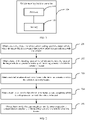
- FIG. 1 is a schematic diagram of a vehicle traveling decision controller 100 according to an embodiment of this application.
- the vehicle traveling decision controller may include a processor 101 and a memory 102.
- the processor 101 may be a central processing unit (central processing unit, CPU).
- the processor 101 may be one processor, or may include a plurality of processors.
- the memory 102 may include a volatile memory such as a random access memory (random access memory, RAM), or the memory may include a non-volatile memory such as a read-only memory (read-only memory, ROM) and a flash memory.
- the memory may alternatively include a combination of the foregoing types of memories.
- the memory 102 may be one memory, or may include a plurality of memories.
- the memory 102 stores computer readable instructions.
- the computer readable instructions may be executed by the processor 101, to implement the method for detecting a complexity of a traveling scenario of a vehicle provided in the embodiments of this application.
- the vehicle traveling decision controller collects traveling data of a forward vehicle in a specific range by using a sensing system, obtains, by combining a positioning system and a high-definition map, a value of each static factor in a traveling scenario in which a current vehicle is located, and comprehensively calculates a complexity of the traveling scenario in which the vehicle is located.
- a processing process of a method for detecting a complexity of a traveling scenario of a vehicle may include the following steps: Step 201: Obtain a traveling speed of the vehicle and a traveling speed of a target vehicle, where the target vehicle is a vehicle that meets a preset distance condition with the vehicle.
- the target vehicle that meets the preset distance condition with the vehicle may be first determined as a research vehicle for subsequently calculating a dynamic complexity of a traveling scenario in which the vehicle is located.
- a method for determining the target vehicle that meets the preset distance condition with the vehicle may be as follows:
- a forward vehicle in the traveling scenario in which the vehicle is located is detected by using a radar, and if there is a forward vehicle in a same lane as the vehicle, a forward vehicle that has a minimum distance from the vehicle is determined as a reference vehicle.
- a traveling speed of the reference vehicle and a component of a distance between the reference vehicle and the vehicle in a traveling direction of the vehicle are obtained by using the radar.
- a component of a distance between a vehicle and the current vehicle in the traveling direction of the current vehicle may also be referred to as a vertical distance between the vehicle and the current vehicle.
- d min V following ⁇ + a max , accel ⁇ 2 2 + V following + a max , accel ⁇ 2 2 a min , brake ⁇ V leading 2 2 b max , brake
- a complexity corresponding to the target vehicle is determined based on the traveling speed of the vehicle and a traveling speed of the target vehicle.
- the determined complexities corresponding to the target vehicles are added to obtain the dynamic complexity of the traveling scenario in which the vehicle is located.
- the following describes a method for determining the complexity corresponding to the target vehicle.
- an included angle ⁇ ij between the traveling direction of the vehicle and a relative traveling speed between the vehicle and the target vehicle is calculated.
- V h_ij is a horizontal relative speed between the vehicle and the target vehicle, namely, a value obtained by subtracting a component of the traveling speed of the vehicle in a horizontal direction perpendicular to the traveling direction of the vehicle from a component of the traveling speed of the target vehicle in the horizontal direction perpendicular to the traveling direction of the vehicle
- V v_ij is a vertical relative speed between the vehicle and the target vehicle, namely, a value obtained by subtracting a component of the traveling speed of the vehicle in the traveling direction of the vehicle from a component of the traveling speed of the target vehicle in the traveling direction of the vehicle.
- An initial complexity f ( ⁇ ij ) corresponding to the target vehicle may be obtained.
- the initial complexity f ( ⁇ ij ) corresponding to the target vehicle may be corrected based on a distance between the target vehicle and the vehicle and the relative speed between the target vehicle and the vehicle, to obtain the complexity corresponding to the target vehicle.
- the correction method may include the following steps:
- Step 203 Obtain static information of each static factor in the traveling scenario in which the vehicle is currently located.
- the static factor includes a road type, a quantity of co-directional lanes, a lane width, a central isolation form, an isolation form between a motor vehicle and a non-motor vehicle, a traffic sign, and a traffic light.
- a positioning system may be used to determine a current location, and a high-definition map may be used to determine the static information of each static factor at the current location (the traveling scenario in which the vehicle is located) of the vehicle.
- the road type is an urban expressway
- the quantity of co-directional lanes is 2
- a lane width greater than 3.5 m is a wide lane
- the central isolation form is greening isolation
- the isolation form between the motor vehicle and the non-motor vehicle is greening isolation
- the traffic sign is that there is a speed limit sign
- the traffic light is that there is a traffic light.
- Static information of the road type may be an urban expressway, a trunk road, a secondary trunk road, and a branch way.
- Static information of the quantity of co-directional lanes may be 1, 2, 3, 4, 5, 6, and the like.
- Static information of the lane width may be 3 m, 3.5 m, 4 m, 4.5 m, and the like.
- Static information of the central isolation form may be: there is no central isolation, marking-line isolation, a hard barrier, and greening isolation.
- Static information of the isolation form between the motor vehicle and the non-motor vehicle may be: there is no isolation between the motor vehicle and the non-motor vehicle, marking-line isolation, a hard barrier, and greening isolation.
- Static information of the traffic sign may be: a speed limit sign of 40 km/h, a speed limit sign of 60 km/h, there is no speed limit sign, and the like.
- Static information of the traffic light is that the traffic light is a red light, the traffic light is a green light, the traffic light is a yellow light, and there is no traffic light.
- Step 204 Obtain, based on the static information of each static factor, a static complexity of the traveling scenario in which the vehicle is located.
- values of a plurality of static factors in the traveling scenario in which the vehicle is located may be first obtained based on determined static information of the plurality of static factors.
- complexities respectively corresponding to the values of the plurality of static factors in the traveling scenario in which the vehicle is located are determined based on a correspondence between a value of a static factor and a complexity.
- the static complexity of the traveling scenario in which the vehicle is located is obtained based on the complexities respectively corresponding to the plurality of static factors.
- the static information of the central isolation form may be directly determined as a value of the central isolation form.
- the static information of the isolation form between the motor vehicle and the non-motor vehicle may be directly determined as a value of the isolation form between the motor vehicle and the non-motor vehicle.
- the static information corresponding to the traffic light is that the traffic light is a red light, the traffic light is a green light, and the traffic light is a yellow light, a same value "there is a traffic light" may be correspondingly determined.
- a corresponding value may be "there is no traffic light”.
- each static factor may be shown in the following Table 1.
- Table 1 Static factor Value Road type Urban expressway, trunk road, secondary trunk road, and branch way Quantity of co-directional lanes 1, 2, 3, 4, 5, and a value greater than 5
- Central isolation form There is no central isolation, marking-line isolation, hard barrier, and greening isolation Isolation form between a motor vehicle and a non-motor vehicle
- Traffic sign There is a speed limit sign and there is no speed limit sign Traffic light
- Traffic light There is a traffic light and there is no traffic light
- a weight corresponding to the static factor may be obtained based on a correspondence between a static factor and a weight, and a complexity corresponding to the static factor is multiplied by the weight corresponding to the static factor, to obtain a weighted complexity of the static factor.
- the correspondence between a static factor and a weight may be shown in Table 3.
- a technical person may pre-determine a complexity corresponding to each value of each static factor.
- a method for determining the complexity corresponding to each value of each static factor may be as follows:
- N sample images corresponding to the value are obtained.
- N is an integer greater than 1.
- the sample image may be obtained in the following manner: The sample image is captured by using a high-definition streetscape map, is photographed in the field, is downloaded by using the Internet, or the like A method for obtaining the sample image is not limited in this embodiment of this application. Then, image recognition is separately performed on the N sample images to obtain a predicted value corresponding to each sample image. A quantity M of sample images whose corresponding predicted values are different from corresponding ground truth values is counted. The ground truth value is used to uniquely identify a value. A ratio of M to N is determined as the complexity corresponding to the value. The following uses determining of a complexity corresponding to greening isolation as an example for description.
- 100 streetscape images with greening isolation are captured as sample images corresponding to greening isolation.
- 100 streetscape images with greening isolation may be photographed in the field as sample images corresponding to greening isolation, or 100 streetscape images with greening isolation may be downloaded, by using the Internet, as sample images corresponding to greening isolation.
- image recognition may be separately performed on the 100 sample images by using an image recognition algorithm.
- the image recognition algorithm may be a trained neural network model or the like.
- Each value of the central isolation form may correspond to one ground truth value, for example, no central isolation is 0, marking-line isolation is 1, a hard barrier is 2, and greening isolation is 3. After image recognition is performed on each sample image, a predicted value corresponding to the sample image may be obtained.
- the predicted value is different from the ground truth value, it is considered that recognition is incorrect, and a quantity of sample images that are incorrectly recognized is recorded. For example, if there are 90 sample images that are incorrectly recognized, the quantity 90 of sample images that are incorrectly recognized is divided by the total quantity 100 of sample images to obtain a recognition error rate 90%.
- the recognition error rate may be used as the complexity corresponding to greening isolation.
- the weight corresponding to each static factor may be determined and stored by using an analytic hierarchy process.
- the following describes a process of determining, by using the analytic hierarchy process, the weight corresponding to the static factor.
- a technical person may fill in a static factor importance determining matrix table based on a ratio scale table used when static factors are compared.
- the static factor importance determining matrix table may be shown in Table 4, and the ratio scale table may be shown in the following Table 5.
- V k M k n
- a feature vector W k of a static factor importance determining matrix namely, the weight corresponding to the static factor.
- Step 205 Determine, based on the dynamic complexity and the static complexity, a comprehensive complexity of the traveling scenario in which the vehicle is located.
- the determined dynamic complexity and the determined static complexity may be directly added to obtain the comprehensive complexity of the traveling scenario in which the vehicle is located.
- an environment factor of the traveling scenario in which the vehicle is located may be considered to comprehensively determine the comprehensive complexity of the traveling scenario in which the vehicle is located.
- a determining method may be as follows: obtaining environment information of an environment factor in the traveling scenario in which the vehicle is located; obtaining a value of the environment factor based on the environment information of the environment factor; determining, based on a stored correspondence between a value of an environment factor and a complexity correction coefficient, a target complexity correction coefficient corresponding to the environment factor in the traveling scenario in which the vehicle is located; and multiplying, by the target complexity correction coefficient, a value obtained by adding the dynamic complexity and the static complexity, to obtain the comprehensive complexity of the traveling scenario in which the vehicle is located.
- the environment factor includes lighting, weather, and a road surface condition.
- an environment image in the traveling scenario may be obtained by using a camera of a sensing system of the vehicle, and environment information of each environment factor is recognized from the environment image by using a pattern recognition algorithm constructed in advance. Because an output of the pattern recognition algorithm is several pieces of preset possible environment information, the environment information of the environment factor may be directly determined as the value of the environment factor.
- a value of each environment factor may be shown in the following Table 6. Table 6 Environment factor Value Lighting Daytime, dusk or dawn, night with lighting, and night without lighting Weather Sunny day, cloudy day, rainy day, snowy day, and foggy day Road surface condition Dryness, wetness, accumulated snow, and ice
- Table 7 The correspondence between a value of each environment factor and a complexity correction coefficient may be shown in the following Table 7. It should be noted that Table 7 merely provides an example of the complexity correction coefficient.
- Table 7 Environment factor Value (complexity correction coefficient) Lighting Daytime (1), dusk or dawn (1.2), night with lighting (1.5), and night without lighting (2) Weather Sunny day (1), cloudy day (1.2), rainy day (1.8), snowy day (1.5), and foggy day (2) Road surface condition Dryness (1), wetness (1.5), accumulated snow (1.8), and ice (2)
- a complexity correction coefficient corresponding to each environment factor in the traveling scenario in which the vehicle is located may be determined by querying the correspondence between a value of each environment factor and a complexity correction coefficient. Subsequently, the determined complexity correction coefficients corresponding to the environment factors are multiplied to obtain the target complexity correction coefficient.
- the obtained value of each environment factor is as follows: The lighting is daytime, the weather is a rainy day, and the road surface condition is wetness. Correspondingly, it may be determined, through query, that a complexity correction coefficient corresponding to the daytime is 1, a complexity correction coefficient corresponding to the rainy day is 1.8, and a complexity correction coefficient corresponding to the wetness is 1.5, and the three complexity correction coefficients are multiplied to obtain the target complexity correction coefficient 2.7.
- the obtained target complexity correction coefficient is multiplied by a sum of the determined dynamic complexity and the determined static complexity, to obtain the comprehensive complexity of the traveling scenario in which the vehicle is located.
- the comprehensive complexity may be displayed on a display screen in the self-driving car in real time, so that a driver can learn of, in real time, the complexity of the traveling environment in which the vehicle is located.
- a danger complexity threshold may be set.
- the manual driving takeover prompt may be displayed on the display screen.
- a voice prompt may be provided at the same time, to prompt the driver to perform manual driving due to a high complexity of a current driving environment.
- the first determining module 620 is configured to:
- the first determining module 620 is configured to:
- the first determining module 620 is configured to:
- the third determining module 640 is configured to:
- the static factor includes at least one of a road type, a quantity of co-directional lanes, a lane width, a central isolation form, an isolation form between a motor vehicle and a non-motor vehicle, a traffic sign, and a traffic light.
- the apparatus further includes:
- the environment factor includes at least one of lighting, weather, and a road surface condition.
- the obtaining module 610 is configured to:
- the apparatus for detecting a complexity of a traveling scenario of a vehicle provided in the foregoing embodiment detects the complexity of the traveling scenario of the vehicle
- division of the foregoing functional modules is merely used as an example for description.
- the foregoing functions may be allocated to different functional modules and implemented as required, that is, an internal structure of a vehicle traveling decision controller is divided into different functional modules, to implement all or some of the functions described above.
- the apparatus for detecting a complexity of a traveling scenario of a vehicle provided in the foregoing embodiment belongs to a same concept as the embodiment of the method for detecting a complexity of a traveling scenario of a vehicle. For a specific implementation process thereof, refer to the method embodiment. Details are not described herein again.
- the computer instructions may be transmitted from a website, computer, server, or data center to another website, computer, server, or data center in a wired (for example, a coaxial optical cable, an optical fiber, or a digital subscriber line) or wireless (for example, infrared, radio, or microwave) manner.
- the computer-readable storage medium may be any usable medium accessible by a device, or a data storage device, such as a server or a data center, integrating one or more usable media.
- the usable medium may be a magnetic medium (such as a floppy disk, a hard disk, and a magnetic tape), or may be an optical medium (such as a digital video disc (Digital Video Disk, DVD)) or a semiconductor medium (such as a solid-state drive).
Landscapes
- Engineering & Computer Science (AREA)
- Physics & Mathematics (AREA)
- Mechanical Engineering (AREA)
- Automation & Control Theory (AREA)
- Transportation (AREA)
- Mathematical Physics (AREA)
- General Physics & Mathematics (AREA)
- Multimedia (AREA)
- Theoretical Computer Science (AREA)
- Human Computer Interaction (AREA)
- Life Sciences & Earth Sciences (AREA)
- Atmospheric Sciences (AREA)
- Traffic Control Systems (AREA)
Abstract
Description
- This application relates to the field of self-driving technologies, and in particular, to a method and an apparatus for detecting a complexity of a traveling scenario of a vehicle.
- With rapid development of self-driving cars, traffic safety of the self-driving car also attracts more attention from people. In a high-complexity driving scenario, self-driving of the self-driving car may be dangerous, and thus a driver may needs to take over self-driving to perform manual driving. In this way, to prompt, in the high-complexity traveling scenario, the driver to be ready to take over driving, it is greatly important to determine a complexity of the traveling scenario.
- Currently, the following method may be generally used to determine the complexity of the traveling scenario: An in-vehicle global positioning system (Global Positioning System, GPS) and a high-definition map are used to determine an actual value of a static factor and a traveling speed of a current vehicle that affect vehicle traveling safety and that are in a traveling scenario in which the vehicle is currently located. The static factor includes a quantity of lanes, a middle separation form, a width of a lane in which the vehicle is located, and the like. A complexity corresponding to the actual value of each static factor is determined based on pre-stored complexities corresponding to different values of the static factor. A complexity corresponding to the traveling speed of the vehicle is determined based on a complexity corresponding to a traveling speed interval. Then, the determined complexities are added to obtain a complexity of the traveling scenario in which the vehicle is currently located.
- A conventional technology has at least the following problem:
In the traveling scenario of the vehicle, in addition to the static factor and the traveling speed of the vehicle that are mentioned in the foregoing method, a traveling status of another vehicle in a specific range around the vehicle further affects vehicle traveling safety. Therefore, the complexity that is of the traveling scenario and that is determined only based on the foregoing factor cannot fully reflect an actual complexity of the traveling scenario in which the vehicle is currently located. Consequently, self-driving of the vehicle has a safety risk. - Embodiments of this application provide a method and an apparatus for detecting a complexity of a traveling scenario of a vehicle, to overcome a problem that a complexity determined in a related technology cannot fully reflect an actual complexity of the traveling scenario in which the vehicle is currently located.
- According to a first aspect, a method for detecting a complexity of a traveling scenario of a vehicle is provided, where the method includes:
obtaining a traveling speed of the vehicle and a traveling speed of a target vehicle, where the target vehicle is a target vehicle that meets a preset distance condition with the vehicle; obtaining, based on the traveling speed of the vehicle and the traveling speed of the target vehicle, a dynamic complexity of a traveling scenario in which the vehicle is located; determining static information of each static factor in the traveling scenario in which the vehicle is currently located; determining, based on the static information of each static factor, a static complexity of the traveling scenario in which the vehicle is located; and determining, based on the dynamic complexity and the static complexity, a comprehensive complexity of the traveling scenario in which the vehicle is located. - In the solution shown in this embodiment of this application, the traveling speed of the target vehicle in a specific range of the vehicle may be detected by using an in-vehicle radar, and the dynamic complexity of the traveling scenario in which the vehicle is located is calculated based on the traveling speed of the target vehicle and the traveling speed of the vehicle. The dynamic complexity is used to represent a degree to which a traveling status of the target vehicle in the traveling scenario in which the vehicle is located affects traveling of the vehicle. In addition, the static information of each static factor in the traveling scenario in which the vehicle is located may also be obtained by using an in-vehicle GPS and a high-definition map. For example, if the static factor is a lane width, the static information may be an actual lane width value.
- The static complexity of the traveling scenario in which the vehicle is located is obtained based on the static information of each static factor. The static complexity is used to represent a degree to which the static factor in the traveling scenario in which the vehicle is located affects traveling of the vehicle. Finally, the dynamic complexity of the traveling scenario in which the vehicle is located may be calculated by combining the dynamic complexity and the static complexity. In this solution, the static factor and the traveling status of the target vehicle in the specific range are combined to comprehensively determine the comprehensive complexity of the traveling scenario in which the vehicle is located, so that an actual complexity of the traveling scenario in which the vehicle is currently located can be more fully reflected.
- In a possible implementation, the obtaining, based on the traveling speed of the vehicle and the traveling speed of the target vehicle, a dynamic complexity of a traveling scenario in which the vehicle is located includes:
- obtaining, for each target vehicle based on the traveling speed of the vehicle and a traveling speed of the target vehicle, a complexity corresponding to the target vehicle; and
- adding the complexities corresponding to the target vehicles to obtain the dynamic complexity of the traveling scenario in which the vehicle is located.
- In the solution shown in this embodiment of this application, when the dynamic complexity is determined, the complexity corresponding to each target vehicle may be calculated by using each target vehicle as a research object, and the dynamic complexity of the traveling scenario in which the vehicle is located is calculated by combining the complexities corresponding to the target vehicles.
- In a possible implementation, the obtaining, based on the traveling speed of the vehicle and a traveling speed of the target vehicle, a complexity corresponding to the target vehicle includes:
- obtaining an included angle θij between a traveling direction of the vehicle and a relative traveling speed between the vehicle and the target vehicle; and
- determining, based on the included angle θij , the complexity corresponding to the target vehicle.
- In the solution shown in this embodiment of this application, the relative traveling speed between the vehicle and the target vehicle may be a value obtained by subtracting the traveling speed of the vehicle from the traveling speed of the target vehicle. When the included angle θij between the traveling direction of the vehicle and the relative traveling speed between the vehicle and the target vehicle is calculated, the following method may be used:

-
Vh_ij is a horizontal relative speed between the vehicle and the target vehicle, namely, a value obtained by subtracting a component of the traveling speed of the vehicle in a horizontal direction perpendicular to the traveling direction of the vehicle from a component of the traveling speed of the target vehicle in the horizontal direction perpendicular to the traveling direction of the vehicle, andV v_ij is a vertical relative speed between the vehicle and the target vehicle, namely, a value obtained by subtracting a component of the traveling speed of the vehicle in the traveling direction of the vehicle from a component of the traveling speed of the target vehicle in the traveling direction of the vehicle. - In a possible implementation, the determining, based on the included angle θij , the complexity corresponding to the target vehicle includes:
- substituting the included angle θij into the following equation:

- correcting, based on a distance between the target vehicle and the vehicle and the relative speed between the target vehicle and the vehicle, the initial complexity f(θij ) corresponding to the target vehicle, to obtain the complexity corresponding to the target vehicle.
- In the solution shown in this embodiment of this application, to more accurately calculate the complexity corresponding to each target vehicle, the initial complexity may be corrected based on the distance between the target vehicle and the vehicle and the relative speed between the target vehicle and the vehicle.
- In a possible implementation, the correcting, based on a distance between the target vehicle and the vehicle and the relative speed between the target vehicle and the vehicle, the initial complexity f(θij ) corresponding to the target vehicle, to obtain the complexity corresponding to the target vehicle includes:
- obtaining a first safe distance between the vehicle and the target vehicle based on the traveling speed, a maximum deceleration, and a minimum deceleration of the vehicle, the traveling speed and a maximum deceleration of the target vehicle, and a preset driver reaction time;
- calculating a first difference between a preset danger distance and a component of the distance between the target vehicle and the vehicle in the traveling direction of the vehicle;
- calculating a second difference between the first safe distance and the preset danger distance;
- calculating a ratio between the first difference and the second difference to obtain a standard vertical distance p between the vehicle and the target vehicle;
- substituting the standard vertical distance P into the following equation: f 1(p) = (1 - p)lg(1/p), to obtain a vertical correction coefficient f 1(p);
- calculating a third difference between a preset danger horizontal relative speed and a horizontal relative speed between the target vehicle and the vehicle;
- calculating a fourth difference between a preset safe horizontal relative speed and the preset danger horizontal relative speed;
- calculating a ratio between the third difference and the fourth difference to obtain a standard horizontal relative speed q between the vehicle and the target vehicle;
- substituting the standard horizontal relative speed q into the following equation: f 1(q) = (1 - q)lg(1/q), to obtain a horizontal correction coefficient f 1(q) ; and
- multiplying the initial complexity f(θij ) corresponding to the target vehicle, the vertical correction coefficient f 1(q) , and the horizontal correction coefficient f 1(q) , to obtain the complexity corresponding to the target vehicle.
- In the solution shown in this embodiment of this application, when the initial complexity is corrected, consideration may be given in two directions: a horizontal direction and a vertical direction. The horizontal direction is the horizontal direction perpendicular to the traveling direction of the vehicle, and the vertical direction is the traveling direction of the vehicle. During horizontal correction, correction may be performed based on the horizontal relative speed between the vehicle and the target vehicle. During vertical correction, correction may be performed based on the vertical distance between the vehicle and the target vehicle.
- In a possible implementation, the obtaining, based on the static information of each static factor, a static complexity of the traveling scenario in which the vehicle is located includes:
- obtaining values of the plurality of static factors based on static information of the plurality of static factors, and obtaining, based on a correspondence between the values of the plurality of static factors and complexities, complexities respectively corresponding to the plurality of static factors; and
- obtaining, based on the complexities respectively corresponding to the plurality of static factors, the static complexity of the traveling scenario in which the vehicle is located.
- In the solution shown in this embodiment of this application, a value of each static factor may be first determined based on the static information of the static factor. For example, the static factor is a lane width, and the corresponding static information may be 3 m, 3.5 m, 4 m, 4.5 m, and the like. In this case, the value of the static factor may be a wide lane (lane width ≥ 3.5 m) and a narrow lane (lane width < 3.5 m). Then, the complexities respectively corresponding to the plurality of static factors is obtained based on the correspondence between a value of a static factor and a complexity. Finally, the complexities respectively corresponding to the plurality of static factors are added to obtain the static complexity of the traveling scenario in which the vehicle is located.
- In a possible implementation, the determining, based on the complexities respectively corresponding to the plurality of static factors, the static complexity of the traveling scenario in which the vehicle is located includes:
- obtaining weights respectively corresponding to the plurality of static factors;
- respectively multiplying the complexities corresponding to the values of the plurality of static factors by the corresponding weights to obtain weighted complexities respectively corresponding to the plurality of static factors; and
- adding the weighted complexities corresponding to the plurality of static factors to obtain the static complexity of the traveling scenario in which the vehicle is located.
- In the solution shown in this embodiment of this application, considering that the static factors impose different impacts on traveling of the vehicle, when the static complexity of the traveling scenario in which the vehicle is located is determined based on the complexity corresponding to each static factor, the complexity corresponding to each static factor in the traveling scenario in which the vehicle is located may be first multiplied by the weight corresponding to the static factor, to obtain the weighted complexity corresponding to the static factor, and then the weighted complexities corresponding to the static factors are added to obtain the static complexity of the traveling scenario in which the vehicle is located.
- In a possible implementation, the method further includes:
- for a first value of a first static factor, obtaining N sample images corresponding to the first value, where N is an integer greater than 1;
- separately performing image recognition on the N sample images to obtain a predicted value corresponding to each sample image;
- counting a quantity M of sample images whose corresponding predicted values are different from corresponding ground truth values, where the ground truth value is used to uniquely identify the first value; and
- obtaining a ratio of M to N as a complexity corresponding to the first value.
- In the solution shown in this embodiment of this application, for each value of each static factor, a complexity corresponding to the value may be pre-determined, and the value of the static factor and the corresponding complexity are correspondingly stored. When the complexity corresponding to the value of the static factor is pre-determined, N sample images corresponding to the value may be obtained. Then, image recognition is separately performed on the N sample images to obtain a predicted value corresponding to each sample image. A quantity M of sample images whose corresponding predicted values are different from corresponding ground truth values is counted. A ratio of M to N is obtained as the complexity corresponding to the value. When the sample image is obtained, to save manpower, a sample image corresponding to each value of each static factor may be obtained by using a high-definition streetscape map.
- In a possible implementation, the static factor includes at least one of a road type, a quantity of co-directional lanes, a lane width, a central isolation form, an isolation form between a motor vehicle and a non-motor vehicle, a traffic sign, and a traffic light.
- In the solution shown in this embodiment of this application, static information corresponding to the road type may be an urban expressway, a trunk road, a secondary trunk road, and a branch way. In this case, a corresponding value may also be the urban expressway, the trunk road, the secondary trunk road, and the branch way. Static information corresponding to the quantity of co-directional lanes may be 1, 2, 3, 4, 5, 6, and the like. In this case, a corresponding value may be 1, 2, 3, 4, and a value greater than or equal to 5. Static information corresponding to the lane width may be 3 m, 3.5 m, 4 m, 4.5 m, and the like. In this case, a corresponding value may be a wide lane (lane width ≥ 3.5 m) and a narrow lane (lane width < 3.5 m). Static information corresponding to the central isolation form may be: there is no central isolation, marking-line isolation, a hard barrier, and greening isolation. In this case, a corresponding value may also be: there is no central isolation, the marking-line isolation, the hard barrier, and the greening isolation. Static information corresponding to the isolation form between the motor vehicle and the non-motor vehicle may be: there is no isolation between the motor vehicle and the non-motor vehicle, marking-line isolation, a hard barrier, and greening isolation. In this case, a corresponding value may also be: there is no isolation between the motor vehicle and the non-motor vehicle, the marking-line isolation, the hard barrier, and the greening isolation. Static information corresponding to the traffic sign may be: a speed limit sign of 40 km/h, a speed limit sign of 60 km/h, there is no speed limit sign, and the like. In this case, a corresponding value may be that there is a speed limit sign and there is no speed limit sign. Static information corresponding to the traffic light is that the traffic light is a red light, the traffic light is a green light, the traffic light is a yellow light, and there is no traffic light. In this case, a corresponding value may be that there is a traffic light and there is no traffic light.
- In a possible implementation, the method further includes:
- obtaining static information of an environment factor in the traveling scenario in which the vehicle is located;
- obtaining a value of the environment factor based on the environment information of the environment factor; and
- determining, based on a stored correspondence between a value of an environment factor and a complexity correction coefficient, a target complexity correction coefficient corresponding to the environment factor in the traveling scenario in which the vehicle is located; and
- the determining, based on the dynamic complexity and the static complexity, a comprehensive complexity of the traveling scenario in which the vehicle is located includes:
multiplying, by the target complexity correction coefficient, a value obtained by adding the dynamic complexity and the static complexity, to obtain the comprehensive complexity of the traveling scenario in which the vehicle is located. - In the solution shown in this embodiment of this application, in addition to the static factor and the traveling status of the target vehicle, the environment factor is also an important factor that affects traveling of the vehicle. In other words, the environment factor also imposes an impact on the complexity of the traveling scenario in which the vehicle is located. An environment image in the traveling scenario may be obtained by using a camera of a sensing system of the vehicle, environment information of each environment factor is recognized from the environment image by using a pattern recognition algorithm constructed in advance, and then the environment information of the environment factor may be used as a value of the environment factor. In this way, the target complexity correction coefficient corresponding to the value of the environment factor of the traveling scenario in which the vehicle is located may be obtained based on the correspondence between a value of an environment factor and a complexity correction coefficient, and the target complexity correction coefficient is used to correct the dynamic complexity and the static complexity.
- In a possible implementation, the environment factor includes lighting, weather, and a road surface condition.
- In the solution shown in this embodiment of this application, a value corresponding to the lighting may include daytime, dusk or dawn, night with lighting, and night without lighting. A value corresponding to the weather may include a sunny day, a cloudy day, a rainy day, a snowy day, and a foggy day. A value corresponding to the road surface condition may include dryness, wetness, accumulated snow, and ice.
- In a possible implementation, the determining a target vehicle that meets a preset distance condition with the vehicle includes:
- if there is a forward vehicle in a same lane as the vehicle, determining, as a reference vehicle, a forward vehicle that is in the forward vehicle in the same lane as the vehicle and that has a minimum distance from the vehicle;
- determining a traveling speed of the reference vehicle and a component of a distance between the reference vehicle and the vehicle in the traveling direction of the vehicle;
- determining a second safe distance between the vehicle and the reference vehicle based on the traveling speed, a preset maximum acceleration, and a preset minimum deceleration of the vehicle, the traveling speed and a preset maximum deceleration of the reference vehicle, and the preset driver reaction time;
- determining a smaller value in the second safe distance and the component of the distance between the reference vehicle and the vehicle in the traveling direction of the vehicle; and
- determining, as the target vehicle, a forward vehicle in a lane in which the vehicle is located and an adjacent lane, where a component of a distance between the forward vehicle and the vehicle in the traveling direction of the vehicle is not greater than the smaller value; or
- if there is no forward vehicle in a same lane as the vehicle, determining a third safe distance based on the traveling speed, a preset maximum acceleration, and a preset minimum deceleration of the vehicle, a preset forward-vehicle traveling speed, the preset maximum deceleration, and the preset driver reaction time, where the preset forward-vehicle traveling speed is 0; and
- determining, as the target vehicle, a forward vehicle in a lane in which the vehicle is located and an adjacent lane, where a component of a distance between the forward vehicle and the vehicle in the traveling direction of the vehicle is not greater than the third safe distance.
- According to a second aspect, an apparatus for detecting a complexity of a traveling scenario of a vehicle is provided, where the apparatus includes:
- an obtaining module, configured to obtain a traveling speed of the vehicle and a traveling speed of a target vehicle, where the target vehicle is a vehicle that meets a preset distance condition with the vehicle;
- a first determining module, configured to obtain, based on the traveling speed of the vehicle and the traveling speed of the target vehicle, a dynamic complexity of a traveling scenario in which the vehicle is located;
- a second determining module, configured to obtain static information of each static factor in the traveling scenario in which the vehicle is located;
- a third determining module, configured to obtain, based on the static information of each static factor, a static complexity of the traveling scenario in which the vehicle is located; and
- a fourth determining module, configured to obtain, based on the dynamic complexity and the static complexity, a comprehensive complexity of the traveling scenario in which the vehicle is located.
- In a possible implementation, the first determining module is configured to:
- obtain, for each target vehicle based on the traveling speed of the vehicle and a traveling speed of the target vehicle, a complexity corresponding to the target vehicle; and
- add the complexities corresponding to the target vehicles to obtain the dynamic complexity of the traveling scenario in which the vehicle is located.
- In a possible implementation, the first determining module is configured to:
- obtain a relative traveling speed between the vehicle and the target vehicle based on the traveling speed of the vehicle and the traveling speed of the target vehicle;
- obtain an included angle θij between a traveling direction of the vehicle and the relative traveling speed between the vehicle and the target vehicle; and
- obtain, based on the included angle θij , the complexity corresponding to the target vehicle.
- In a possible implementation, the first determining module is configured to:
- substitute the included angle θij into the following equation:

- correct, based on a distance between the target vehicle and the vehicle and the relative traveling speed between the target vehicle and the vehicle, the initial complexity f(θij ) corresponding to the target vehicle, to obtain the complexity corresponding to the target vehicle.
- In a possible implementation, the first determining module is configured to:
- obtain a first safe distance between the vehicle and the target vehicle based on the traveling speed, a maximum deceleration, and a minimum deceleration of the vehicle, the traveling speed and a maximum deceleration of the target vehicle, and a preset driver reaction time;
- calculate a first difference between a preset danger distance and a component of the distance between the target vehicle and the vehicle in the traveling direction of the vehicle;
- calculate a second difference between the first safe distance and the preset danger distance;
- calculate a ratio between the first difference and the second difference to obtain a standard vertical distance p between the vehicle and the target vehicle;
- substitute the standard vertical distance P into the following equation: f 1(p) = (1 - p)lg(1/p), to obtain a vertical correction coefficient f 1(p);
- calculate a third difference between a preset danger horizontal relative speed and a horizontal relative speed between the target vehicle and the vehicle;
- calculate a fourth difference between a preset safe horizontal relative speed and the preset danger horizontal relative speed;
- calculate a ratio between the third difference and the fourth difference to obtain a standard horizontal relative speed q between the vehicle and the target vehicle;
- substitute the standard horizontal relative speed q into the following equation: f 1(q) = (1-q)lg(1/q), to obtain a horizontal correction coefficient f 1(q) ; and
- multiply the initial complexity f(θij ) corresponding to the target vehicle, the vertical correction coefficient f 1(q) , and the horizontal correction coefficient f 1(q), to obtain the complexity corresponding to the target vehicle.
- In a possible implementation, the third determining module is configured to:
- obtain values of the plurality of static factors based on static information of the plurality of static factors, and obtain, based on a correspondence between the values of the plurality of static factors and complexities, complexities respectively corresponding to the plurality of static factors; and
- obtain, based on the complexities respectively corresponding to the plurality of static factors, the static complexity of the traveling scenario in which the vehicle is located.
- In a possible implementation, the third determining module is configured to:
- obtain weights respectively corresponding to the plurality of static factors;
- respectively multiply the complexities corresponding to the values of the plurality of static factors by the corresponding weights to obtain weighted complexities respectively corresponding to the plurality of static factors; and
- add the weighted complexities corresponding to the plurality of static factors to obtain the static complexity of the traveling scenario in which the vehicle is located.
- In a possible implementation, the apparatus further includes:
a counting module, configured to: for a first value of a first static factor, obtain N sample images corresponding to the first value, where N is an integer greater than 1; separately perform image recognition on the N sample images to obtain a predicted value corresponding to each sample image; count a quantity M of sample images whose corresponding predicted values are different from corresponding ground truth values, where the ground truth value is used to uniquely identify the first value; and obtain a ratio of M to N as a complexity corresponding to the first value. - In a possible implementation, the static factor includes at least one of a road type, a quantity of co-directional lanes, a lane width, a central isolation form, an isolation form between a motor vehicle and a non-motor vehicle, a traffic sign, and a traffic light.
- In a possible implementation, the apparatus further includes:
- a correction module, configured to: obtain environment information of an environment factor in the traveling scenario in which the vehicle is located;
- obtain a value of the environment factor based on the environment information of the environment factor; and
- obtain, based on a stored correspondence between a value of an environment factor and a complexity correction coefficient, a target complexity correction coefficient corresponding to the value of the environment factor in the traveling scenario in which the vehicle is located; and
- the fourth module is configured to:
multiply, by the target complexity correction coefficient, a value obtained by adding the dynamic complexity and the static complexity, to obtain the comprehensive complexity of the traveling scenario in which the vehicle is located. - In a possible implementation, the environment factor includes at least one of lighting, weather, and a road surface condition.
- In a possible implementation, the obtaining module is configured to:
- if there is a forward vehicle in a same lane as the vehicle, determine, as a reference vehicle, a forward vehicle that is in the forward vehicle in the same lane as the vehicle and that has a minimum distance from the vehicle;
- obtain a traveling speed of the reference vehicle and a component of a distance between the reference vehicle and the vehicle in the traveling direction of the vehicle;
- obtain a second safe distance between the vehicle and the reference vehicle based on the traveling speed, a preset maximum acceleration, and a preset minimum deceleration of the vehicle, the traveling speed and a preset maximum deceleration of the reference vehicle, and the preset driver reaction time;
- obtain a smaller value in the second safe distance and the component of the distance between the reference vehicle and the vehicle in the traveling direction of the vehicle; and
- use, as the target vehicle, a forward vehicle in a lane in which the vehicle is located and an adjacent lane, where a component of a distance between the forward vehicle and the vehicle in the traveling direction of the vehicle is not greater than the smaller value; or
- if there is no forward vehicle in a same lane as the vehicle, obtain a third safe distance based on the traveling speed, a preset maximum acceleration, and a preset minimum deceleration of the vehicle, a preset forward-vehicle traveling speed, the preset maximum deceleration, and the preset driver reaction time, where the preset forward-vehicle traveling speed is 0; and
- use, as the target vehicle, a forward vehicle in a lane in which the vehicle is located and an adjacent lane, where a component of a distance between the forward vehicle and the vehicle in the traveling direction of the vehicle is not greater than the third safe distance.
- According to a third aspect, a vehicle traveling decision controller is provided, where the vehicle traveling decision controller includes a processor and a memory; and
the memory stores at least one computer readable instruction, and the computer readable instruction is configured to be executed by the processor, to implement the method for detecting a complexity of a traveling scenario of a vehicle according to the first aspect. - According to a fourth aspect, a computer-readable storage medium is provided, including computer readable instructions, where when the computer-readable storage medium is run on a vehicle traveling decision controller, the vehicle traveling decision controller is enabled to perform the method for detecting a complexity of a traveling scenario of a vehicle according to the first aspect.
- According to a fifth aspect, a computer program product including instructions is provided, where when the computer program product is run on a vehicle traveling decision controller, the vehicle traveling decision controller is enabled to perform the method for detecting a complexity of a traveling scenario of a vehicle according to the first aspect.
- The technical solutions provided in this application include at least the following beneficial effects:
- In this application, the static complexity of the traveling scenario in which the vehicle is located is determined based on the static information of each static factor in the traveling scenario in which the vehicle is located. In addition, the dynamic complexity of the traveling scenario in which the vehicle is located is further determined based on the traveling speed of the vehicle and the traveling speed of the target vehicle. The target vehicle is a vehicle that meets the preset distance condition with the vehicle. In this way, the comprehensive complexity of the traveling scenario in which the vehicle is located is comprehensively determined by combining the static complexity determined by using the static factor and the dynamic complexity determined by using a traveling status of a surrounding vehicle. The comprehensive complexity may more fully reflect a complexity of the traveling scenario in which the vehicle is currently located.
-
-
FIG. 1 is a schematic diagram of a structure of a vehicle traveling decision controller according to an embodiment of this application; -
FIG. 2 is a flowchart of a method for detecting a complexity of a traveling scenario of a vehicle according to an embodiment of this application; -
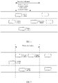
FIG. 3 is a schematic diagram of a target vehicle according to an embodiment of this application; -
FIG. 4 is a schematic diagram of a target vehicle according to an embodiment of this application; -
FIG. 5 is a schematic diagram of a target vehicle according to an embodiment of this application; and -
FIG. 6 is a schematic diagram of a structure of an apparatus for detecting a complexity of a traveling scenario of a vehicle according to an embodiment of this application. - To make objectives, technical solutions, and advantages of this application clearer, the following further describes implementations of this application in detail with reference to the accompanying drawings.
- Embodiments of this application provide a method for detecting a complexity of a traveling scenario of a vehicle, and the method may be applied to a self-driving car. The method may be implemented by a vehicle traveling decision controller in the self-driving car. A sensing system, a positioning system, and the like may be deployed in the self-driving car. The sensing system may include a radar, a camera, and the like. The positioning system may be a global positioning system (Global Positioning System, GPS), a BeiDou system, and the like.
-
FIG. 1 is a schematic diagram of a vehicle travelingdecision controller 100 according to an embodiment of this application. InFIG. 1 , the vehicle traveling decision controller may include a processor 101 and a memory 102. The processor 101 may be a central processing unit (central processing unit, CPU). The processor 101 may be one processor, or may include a plurality of processors. The memory 102 may include a volatile memory such as a random access memory (random access memory, RAM), or the memory may include a non-volatile memory such as a read-only memory (read-only memory, ROM) and a flash memory. The memory may alternatively include a combination of the foregoing types of memories. The memory 102 may be one memory, or may include a plurality of memories. The memory 102 stores computer readable instructions. The computer readable instructions may be executed by the processor 101, to implement the method for detecting a complexity of a traveling scenario of a vehicle provided in the embodiments of this application. - The vehicle traveling decision controller collects traveling data of a forward vehicle in a specific range by using a sensing system, obtains, by combining a positioning system and a high-definition map, a value of each static factor in a traveling scenario in which a current vehicle is located, and comprehensively calculates a complexity of the traveling scenario in which the vehicle is located.
- Referring to
FIG. 2 , a processing process of a method for detecting a complexity of a traveling scenario of a vehicle provided in an embodiment of this application may include the following steps:
Step 201: Obtain a traveling speed of the vehicle and a traveling speed of a target vehicle, where the target vehicle is a vehicle that meets a preset distance condition with the vehicle. - In an implementation, the target vehicle that meets the preset distance condition with the vehicle may be first determined as a research vehicle for subsequently calculating a dynamic complexity of a traveling scenario in which the vehicle is located. A method for determining the target vehicle that meets the preset distance condition with the vehicle may be as follows:
- A forward vehicle in the traveling scenario in which the vehicle is located is detected by using a radar, and if there is a forward vehicle in a same lane as the vehicle, a forward vehicle that has a minimum distance from the vehicle is determined as a reference vehicle. Next, a traveling speed of the reference vehicle and a component of a distance between the reference vehicle and the vehicle in a traveling direction of the vehicle are obtained by using the radar. Herein, a component of a distance between a vehicle and the current vehicle in the traveling direction of the current vehicle may also be referred to as a vertical distance between the vehicle and the current vehicle.
- Then, a second safe distance d min between the reference vehicle and the vehicle is calculated. A calculation formula may be as follows:

- Vfollowing is the traveling speed of the vehicle, Vleading is the traveling speed of the reference vehicle, a max, accel is a preset maximum acceleration of the vehicle, for example, may be 0.2 g, where g is a gravity acceleration, a min, brake is a preset minimum deceleration of the vehicle, for example, may be 0.3 g, bmax, brake represents a preset maximum deceleration of the forward vehicle, for example, may be 0.4 g, and ρ is a preset driver reaction time, for example, may be 2s.
- Subsequently, a smaller value in the determined second safe distance and the vertical distance between the reference vehicle and the vehicle may be determined. A forward vehicle in a lane in which the vehicle is located and an adjacent lane is determined as the target vehicle, where a vertical distance between the forward vehicle and the vehicle is not greater than the smaller value.
FIG. 3 shows a target vehicle determined when the second safe distance is less than the vertical distance between the reference vehicle and the vehicle.FIG. 4 shows a target vehicle determined when the second safe distance is greater than the vertical distance between the reference vehicle and the vehicle. - If there is no forward vehicle in a same lane as the vehicle, it may be assumed that there is a forward vehicle in a same lane as the vehicle, the forward vehicle is used as a reference vehicle, and a traveling speed of the assumed reference vehicle is 0. A third safe distance between the reference vehicle and the vehicle is calculated. A calculation formula of the third safe distance is the same as the calculation formula of the second safe distance, and details are not described herein again.
FIG. 5 shows a target vehicle determined when there is no forward vehicle in a same lane as the vehicle. - Step 202: Obtain, based on the traveling speed of the vehicle and the traveling speed of the target vehicle, a dynamic complexity of a traveling scenario in which the vehicle is located.
- In an implementation, for each target vehicle, a complexity corresponding to the target vehicle is determined based on the traveling speed of the vehicle and a traveling speed of the target vehicle. The determined complexities corresponding to the target vehicles are added to obtain the dynamic complexity of the traveling scenario in which the vehicle is located. The following describes a method for determining the complexity corresponding to the target vehicle.
- First, an included angle θij between the traveling direction of the vehicle and a relative traveling speed between the vehicle and the target vehicle is calculated. A calculation formula may be as follows:
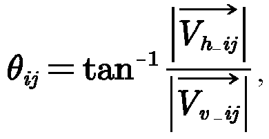
-
Vh_ij is a horizontal relative speed between the vehicle and the target vehicle, namely, a value obtained by subtracting a component of the traveling speed of the vehicle in a horizontal direction perpendicular to the traveling direction of the vehicle from a component of the traveling speed of the target vehicle in the horizontal direction perpendicular to the traveling direction of the vehicle, andVv_ij is a vertical relative speed between the vehicle and the target vehicle, namely, a value obtained by subtracting a component of the traveling speed of the vehicle in the traveling direction of the vehicle from a component of the traveling speed of the target vehicle in the traveling direction of the vehicle. - Next, the calculated included angle θij is substituted into the following formula:

- An initial complexity f(θij ) corresponding to the target vehicle may be obtained.
- Then, the initial complexity f(θij ) corresponding to the target vehicle may be corrected based on a distance between the target vehicle and the vehicle and the relative speed between the target vehicle and the vehicle, to obtain the complexity corresponding to the target vehicle. The correction method may include the following steps:
- 1. Calculate a vertical correction coefficient, where a method for calculating the vertical correction coefficient may be as follows:
- First, a first safe distance between the vehicle and the target vehicle is calculated. A calculation formula of the first safe distance is the same as the calculation formula of the second safe distance, and details are not described herein again. Next, a first difference between a preset danger distance
Dv_max and a vertical distanceDv_ij between the target vehicle and the vehicle is calculated. Then, a second difference between a safety critical valueDv_min and the preset danger distanceD v_max is calculated. The safety critical valueDv_min may be the first safe distance between the vehicle and the target vehicle, andDv_max may be 0 m. Subsequently, a ratio between the first difference and the second difference is calculated to obtain a standard vertical distance p between the vehicle and the target vehicle. The standard vertical distance p may be represented as follows:
- Then, the standard vertical distance p is substituted into the formula f 1(p) = (1-p)lg(1/p), to obtain the vertical correction coefficient f 1(p).
- First, a first safe distance between the vehicle and the target vehicle is calculated. A calculation formula of the first safe distance is the same as the calculation formula of the second safe distance, and details are not described herein again. Next, a first difference between a preset danger distance
- 2. Calculate a horizontal correction coefficient, where a method for calculating the horizontal correction coefficient may be as follows:
- First, a third difference between a preset danger horizontal relative speed
Vh_max and the horizontal relative speedVh_ij between the target vehicle and the vehicle is calculated. Next, a fourth difference between a preset safe horizontal relative speedV h_min and the preset danger horizontal relative speedV h_max is calculated.V h_min may be 3.5 m/s, and indicates that a speed at which the vehicle and the target vehicle approach each other in a horizontal direction is 3.5 m/s.V h_max may be -3.5 m/s, and indicates that a speed at which the vehicle and the target vehicle are separated from each other in the horizontal direction is 3.5 m/s. Subsequently, a ratio between the third difference and the fourth difference is calculated to obtain a standard horizontal relative speed q between the vehicle and the target vehicle. The standard horizontal relative speed q may be represented as follows:
- Then, the standard horizontal relative speed q is substituted into the formula f 1(q) = (1 - q)lg(1/q), to obtain the horizontal correction coefficient f 1(q).
- First, a third difference between a preset danger horizontal relative speed
- 3. Multiply the initial complexity f(θij ), the vertical correction coefficient f 1(p), and the horizontal correction coefficient f 1(q), to obtain the complexity corresponding to the target vehicle. It should be noted herein that the sequence of calculating the vertical correction coefficient and the horizontal correction coefficient is merely an example. The sequence of calculating the two correction coefficients is not limited in this embodiment of this application, and the two correction coefficients may be calculated in parallel in a possible implementation.
- Step 203: Obtain static information of each static factor in the traveling scenario in which the vehicle is currently located.
- The static factor includes a road type, a quantity of co-directional lanes, a lane width, a central isolation form, an isolation form between a motor vehicle and a non-motor vehicle, a traffic sign, and a traffic light.
- In an implementation, a positioning system may be used to determine a current location, and a high-definition map may be used to determine the static information of each static factor at the current location (the traveling scenario in which the vehicle is located) of the vehicle. For example, the following is obtained: In the traveling scenario in which the vehicle is currently located, the road type is an urban expressway, the quantity of co-directional lanes is 2, a lane width greater than 3.5 m is a wide lane, the central isolation form is greening isolation, the isolation form between the motor vehicle and the non-motor vehicle is greening isolation, the traffic sign is that there is a speed limit sign, and the traffic light is that there is a traffic light. The following describes possible static information of each static factor.
- Static information of the road type may be an urban expressway, a trunk road, a secondary trunk road, and a branch way. Static information of the quantity of co-directional lanes may be 1, 2, 3, 4, 5, 6, and the like. Static information of the lane width may be 3 m, 3.5 m, 4 m, 4.5 m, and the like. Static information of the central isolation form may be: there is no central isolation, marking-line isolation, a hard barrier, and greening isolation. Static information of the isolation form between the motor vehicle and the non-motor vehicle may be: there is no isolation between the motor vehicle and the non-motor vehicle, marking-line isolation, a hard barrier, and greening isolation. Static information of the traffic sign may be: a speed limit sign of 40 km/h, a speed limit sign of 60 km/h, there is no speed limit sign, and the like. Static information of the traffic light is that the traffic light is a red light, the traffic light is a green light, the traffic light is a yellow light, and there is no traffic light.
- Step 204: Obtain, based on the static information of each static factor, a static complexity of the traveling scenario in which the vehicle is located.
- In an implementation, values of a plurality of static factors in the traveling scenario in which the vehicle is located may be first obtained based on determined static information of the plurality of static factors. Next, complexities respectively corresponding to the values of the plurality of static factors in the traveling scenario in which the vehicle is located are determined based on a correspondence between a value of a static factor and a complexity. Finally, the static complexity of the traveling scenario in which the vehicle is located is obtained based on the complexities respectively corresponding to the plurality of static factors.
- Because the static factor has various static information, if each piece of static information independently corresponds to one value, the correspondence between a value of a static factor and a complexity is relatively complex. Therefore, for some static information, a plurality of pieces of static information may correspond to one value. The following describes a relationship between the static information of the static factor and the value of the static factor.
- The static information of the road type may be directly determined as a value of the road type, that is, values respectively corresponding to the static information: the urban expressway, the trunk road, the secondary trunk road, and the branch way may also be the urban expressway, the trunk road, the secondary trunk road, and the branch way. When the static information of the quantity of co-directional lanes is 1 to 4, the static information of the quantity of co-directional lanes may be directly determined as a value of the quantity of co-directional lanes. When the static information of the quantity of co-directional lanes is 5, 6, 7, and the like, a same value "≥5" may be correspondingly determined. When the static information of the lane width is 3 m and 3.5 m, a same value "≤3.5 m" may be correspondingly determined. When the static information of the lane width is 4 m, 4.5 m, and the like, a same value ">3.5 m" may be correspondingly determined. The static information of the central isolation form may be directly determined as a value of the central isolation form. The static information of the isolation form between the motor vehicle and the non-motor vehicle may be directly determined as a value of the isolation form between the motor vehicle and the non-motor vehicle. When the static information of the traffic sign is a speed limit sign of 40 km/h, a speed limit sign of 60 km/h, and the like, a corresponding value may be "there is a speed limit sign". When the static information of the traffic sign is that there is no speed limit sign, a corresponding value may be "there is no speed limit sign". When the static information corresponding to the traffic light is that the traffic light is a red light, the traffic light is a green light, and the traffic light is a yellow light, a same value "there is a traffic light" may be correspondingly determined. When the static information corresponding to the traffic light is that there is no traffic light, a corresponding value may be "there is no traffic light".
- A value of each static factor may be shown in the following Table 1.
Table 1 Static factor Value Road type Urban expressway, trunk road, secondary trunk road, and branch way Quantity of co-directional lanes 1, 2, 3, 4, 5, and a value greater than 5 Lane width Wide lane (lane width ≥ 3.5 m) and narrow lane (lane width < 3.5 m) Central isolation form There is no central isolation, marking-line isolation, hard barrier, and greening isolation Isolation form between a motor vehicle and a non-motor vehicle There is no isolation between the motor vehicle and the non-motor vehicle, marking-line isolation, hard barrier, and greening isolation Traffic sign There is a speed limit sign and there is no speed limit sign Traffic light There is a traffic light and there is no traffic light - The correspondence between a value of a static factor and a complexity may be shown in Table 2.
Table 2 Static factor Value (complexity) Road type Urban expressway (c 1, 1), trunk road (c 1, 2), secondary trunk road (c 1, 3 ), and branch way (c 1, 4 ) Quantity of co-directional lanes 1 (c 2, 1 ), 2 (c 2 , 2), 3 (c 2, 3), 4 (c 2, 4 ), 5, and a value greater than 5 (c 2, 5 ) Lane width Wide lane (c 3, 1 ) and narrow lane (c 3, 2 ) Central isolation form There is no central isolation (c 4, 1 ), marking-line isolation (c 4, 2), hard barrier (c 4, 3 ), and greening isolation (c 4, 4 ) Isolation form between a motor vehicle and a non-motor vehicle There is no isolation between the motor vehicle and the non-motor vehicle (c 5, 1 ), marking-line isolation (c 5, 2 ), hard barrier (c 5, 3 ), and greening isolation (c 5, 4 ) Traffic sign There is a speed limit sign (c 6, 1) and there is no speed limit sign (c 6, 2) Traffic light There is a traffic light (c 7, 1) and there is no traffic light (c 7, 2) - For each static factor, a weight corresponding to the static factor may be obtained based on a correspondence between a static factor and a weight, and a complexity corresponding to the static factor is multiplied by the weight corresponding to the static factor, to obtain a weighted complexity of the static factor. The correspondence between a static factor and a weight may be shown in Table 3.
- Finally, the weighted complexities corresponding to the static factors are added to obtain the static complexity of the traveling scenario in which the vehicle is located.
Table 3 Static factor Weight Road type W 1 Quantity of co-directional lanes W 2 Lane width W 3 Central isolation form W 4 Isolation form between a motor vehicle and a non-motor vehicle W 5 Traffic sign W 6 Traffic light W 7 - In a possible implementation, a technical person may pre-determine a complexity corresponding to each value of each static factor. A method for determining the complexity corresponding to each value of each static factor may be as follows:
- For each value of each static factor, N sample images corresponding to the value are obtained. N is an integer greater than 1. The sample image may be obtained in the following manner: The sample image is captured by using a high-definition streetscape map, is photographed in the field, is downloaded by using the Internet, or the like A method for obtaining the sample image is not limited in this embodiment of this application. Then, image recognition is separately performed on the N sample images to obtain a predicted value corresponding to each sample image. A quantity M of sample images whose corresponding predicted values are different from corresponding ground truth values is counted. The ground truth value is used to uniquely identify a value. A ratio of M to N is determined as the complexity corresponding to the value. The following uses determining of a complexity corresponding to greening isolation as an example for description.
- In the high-definition streetscape map, 100 streetscape images with greening isolation are captured as sample images corresponding to greening isolation. Certainly, 100 streetscape images with greening isolation may be photographed in the field as sample images corresponding to greening isolation, or 100 streetscape images with greening isolation may be downloaded, by using the Internet, as sample images corresponding to greening isolation. Then, image recognition may be separately performed on the 100 sample images by using an image recognition algorithm. Herein, the image recognition algorithm may be a trained neural network model or the like. Each value of the central isolation form may correspond to one ground truth value, for example, no central isolation is 0, marking-line isolation is 1, a hard barrier is 2, and greening isolation is 3. After image recognition is performed on each sample image, a predicted value corresponding to the sample image may be obtained. If the predicted value is different from the ground truth value, it is considered that recognition is incorrect, and a quantity of sample images that are incorrectly recognized is recorded. For example, if there are 90 sample images that are incorrectly recognized, the quantity 90 of sample images that are incorrectly recognized is divided by the
total quantity 100 of sample images to obtain a recognition error rate 90%. The recognition error rate may be used as the complexity corresponding to greening isolation. - The weight corresponding to each static factor may be determined and stored by using an analytic hierarchy process. The following describes a process of determining, by using the analytic hierarchy process, the weight corresponding to the static factor.
- First, a technical person may fill in a static factor importance determining matrix table based on a ratio scale table used when static factors are compared. The static factor importance determining matrix table may be shown in Table 4, and the ratio scale table may be shown in the following Table 5.
- Then, a product of elements bkl in each row of the static factor importance determining matrix table is calculated. A calculation formula may be as follows:

- Subsequently, an nth root Vk of Mk is calculated. A calculation formula may be as follows:

- Finally, a feature vector Wk of a static factor importance determining matrix, namely, the weight corresponding to the static factor, is calculated. A calculation formula may be as follows:
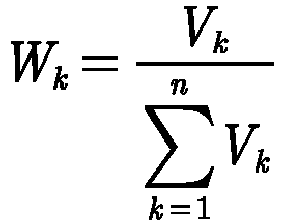

Table 5 Ratio of a factor k to a factor 1 Quantized value Equal importance 1 Slight importance 3 Strong importance 5 Intense importance 7 Extreme importance 9 Intermediate value of two times of adjacent determining 2, 4, 6, 8 - Step 205: Determine, based on the dynamic complexity and the static complexity, a comprehensive complexity of the traveling scenario in which the vehicle is located.
- In an implementation, the determined dynamic complexity and the determined static complexity may be directly added to obtain the comprehensive complexity of the traveling scenario in which the vehicle is located.
- In a possible implementation, an environment factor of the traveling scenario in which the vehicle is located may be considered to comprehensively determine the comprehensive complexity of the traveling scenario in which the vehicle is located. A determining method may be as follows: obtaining environment information of an environment factor in the traveling scenario in which the vehicle is located; obtaining a value of the environment factor based on the environment information of the environment factor; determining, based on a stored correspondence between a value of an environment factor and a complexity correction coefficient, a target complexity correction coefficient corresponding to the environment factor in the traveling scenario in which the vehicle is located; and multiplying, by the target complexity correction coefficient, a value obtained by adding the dynamic complexity and the static complexity, to obtain the comprehensive complexity of the traveling scenario in which the vehicle is located.
- The environment factor includes lighting, weather, and a road surface condition.
- In an implementation, an environment image in the traveling scenario may be obtained by using a camera of a sensing system of the vehicle, and environment information of each environment factor is recognized from the environment image by using a pattern recognition algorithm constructed in advance. Because an output of the pattern recognition algorithm is several pieces of preset possible environment information, the environment information of the environment factor may be directly determined as the value of the environment factor. A value of each environment factor may be shown in the following Table 6.
Table 6 Environment factor Value Lighting Daytime, dusk or dawn, night with lighting, and night without lighting Weather Sunny day, cloudy day, rainy day, snowy day, and foggy day Road surface condition Dryness, wetness, accumulated snow, and ice - The correspondence between a value of each environment factor and a complexity correction coefficient may be shown in the following Table 7. It should be noted that Table 7 merely provides an example of the complexity correction coefficient.
Table 7 Environment factor Value (complexity correction coefficient) Lighting Daytime (1), dusk or dawn (1.2), night with lighting (1.5), and night without lighting (2) Weather Sunny day (1), cloudy day (1.2), rainy day (1.8), snowy day (1.5), and foggy day (2) Road surface condition Dryness (1), wetness (1.5), accumulated snow (1.8), and ice (2) - Then, a complexity correction coefficient corresponding to each environment factor in the traveling scenario in which the vehicle is located may be determined by querying the correspondence between a value of each environment factor and a complexity correction coefficient. Subsequently, the determined complexity correction coefficients corresponding to the environment factors are multiplied to obtain the target complexity correction coefficient.
- For example, the obtained value of each environment factor is as follows: The lighting is daytime, the weather is a rainy day, and the road surface condition is wetness. Correspondingly, it may be determined, through query, that a complexity correction coefficient corresponding to the daytime is 1, a complexity correction coefficient corresponding to the rainy day is 1.8, and a complexity correction coefficient corresponding to the wetness is 1.5, and the three complexity correction coefficients are multiplied to obtain the target complexity correction coefficient 2.7.
- Finally, the obtained target complexity correction coefficient is multiplied by a sum of the determined dynamic complexity and the determined static complexity, to obtain the comprehensive complexity of the traveling scenario in which the vehicle is located.
- In a possible implementation, after the comprehensive complexity of the traveling scenario in which the vehicle is located is calculated, whether to provide a manual driving takeover prompt may be determined based on the calculated comprehensive complexity.
- In an implementation, the comprehensive complexity may be displayed on a display screen in the self-driving car in real time, so that a driver can learn of, in real time, the complexity of the traveling environment in which the vehicle is located. In addition, a danger complexity threshold may be set. When the calculated comprehensive complexity is greater than the set danger complexity threshold, the manual driving takeover prompt may be displayed on the display screen. In addition, a voice prompt may be provided at the same time, to prompt the driver to perform manual driving due to a high complexity of a current driving environment.
- In this embodiment of this application, the static complexity of the traveling scenario in which the vehicle is located is determined based on the static information of each static factor in the traveling scenario in which the vehicle is located. In addition, the dynamic complexity of the traveling scenario in which the vehicle is located is further determined based on the traveling speed of the vehicle and the traveling speed of the target vehicle. The target vehicle is a vehicle that meets the preset distance condition with the vehicle. In this way, the comprehensive complexity of the traveling scenario in which the vehicle is located is comprehensively determined by combining the static complexity determined by using the static factor and the dynamic complexity determined by using a traveling status of a surrounding vehicle. The comprehensive complexity may more fully reflect an actual complexity of the traveling scenario in which the vehicle is currently located.
- Based on a same technical concept, an embodiment of this application further provides an apparatus for detecting a complexity of a traveling scenario of a vehicle. As shown in
FIG. 6 , the apparatus includes: - an obtaining
module 610, configured to obtain a traveling speed of the vehicle and a traveling speed of a target vehicle, where the target vehicle is a vehicle that meets a preset distance condition with the vehicle, and the obtaining function instep 201 and another implicit step may be specifically implemented; - a first determining
module 620, configured to obtain, based on the traveling speed of the vehicle and the traveling speed of the target vehicle, a dynamic complexity of a traveling scenario in which the vehicle is located, where the obtaining function instep 202 and another implicit step may be specifically implemented; - a second determining
module 630, configured to obtain static information of a static factor in the traveling scenario in which the vehicle is located, where the obtaining function instep 203 and another implicit step may be specifically implemented; - a third determining
module 640, configured to obtain, based on the static information of each static factor, a static complexity of the traveling scenario in which the vehicle is located, where the obtaining function instep 204 and another implicit step may be specifically implemented; and - a fourth determining
module 650, configured to obtain, based on the dynamic complexity and the static complexity, a comprehensive complexity of the traveling scenario in which the vehicle is located, where the obtaining function instep 205 and another implicit step may be specifically implemented. - In a possible implementation, the first determining
module 620 is configured to: - obtain, for each target vehicle based on the traveling speed of the vehicle and a traveling speed of the target vehicle, a complexity corresponding to the target vehicle; and
- add the complexities corresponding to the target vehicles to obtain the dynamic complexity of the traveling scenario in which the vehicle is located.
- In a possible implementation, the first determining
module 620 is configured to: - obtain a relative traveling speed between the vehicle and the target vehicle based on the traveling speed of the vehicle and the traveling speed of the target vehicle;
- obtain an included angle θij between a traveling direction of the vehicle and the relative traveling speed between the vehicle and the target vehicle; and
- obtain, based on the included angle θij , the complexity corresponding to the target vehicle.
- In a possible implementation, the first determining
module 620 is configured to: - substitute the included angle θij into the following equation:

- correct, based on a distance between the target vehicle and the vehicle and the relative traveling speed between the target vehicle and the vehicle, the initial complexity f(θij ) corresponding to the target vehicle, to obtain the complexity corresponding to the target vehicle.
- In a possible implementation, the first determining
module 620 is configured to: - obtain a first safe distance between the vehicle and the target vehicle based on the traveling speed, a maximum deceleration, and a minimum deceleration of the vehicle, the traveling speed and a maximum deceleration of the target vehicle, and a preset driver reaction time;
- calculate a first difference between a preset danger distance and a component of the distance between the target vehicle and the vehicle in the traveling direction of the vehicle;
- calculate a second difference between the first safe distance and the preset danger distance;
- calculate a ratio between the first difference and the second difference to obtain a standard vertical distance p between the vehicle and the target vehicle;
- substitute the standard vertical distance P into the following equation: f 1(p) = (1 - p)lg(1/p), to obtain a vertical correction coefficient f 1(p);
- calculate a third difference between a preset danger horizontal relative speed and a horizontal relative speed between the target vehicle and the vehicle;
- calculate a fourth difference between a preset safe horizontal relative speed and the preset danger horizontal relative speed;
- calculate a ratio between the third difference and the fourth difference to obtain a standard horizontal relative speed q between the vehicle and the target vehicle;
- substitute the standard horizontal relative speed q into the following equation: f 1(q) = (1 - q)lg(1/q), to obtain a horizontal correction coefficient f 1(q) ; and
- multiply the initial complexity f(θij ) corresponding to the target vehicle, the vertical correction coefficient f 1(q) , and the horizontal correction coefficient f 1(q) , to obtain the complexity corresponding to the target vehicle.
- In a possible implementation, the third determining
module 640 is configured to: - obtain values of the plurality of static factors based on static information of the plurality of static factors, and obtain, based on a correspondence between the values of the plurality of static factors and complexities, complexities respectively corresponding to the plurality of static factors; and
- obtain, based on the complexities respectively corresponding to the plurality of static factors, the static complexity of the traveling scenario in which the vehicle is located.
- In a possible implementation, the third determining
module 640 is configured to: - obtain weights respectively corresponding to the plurality of static factors;
- respectively multiply the complexities corresponding to the values of the plurality of static factors by the corresponding weights to obtain weighted complexities respectively corresponding to the plurality of static factors; and
- add the weighted complexities corresponding to the plurality of static factors to obtain the static complexity of the traveling scenario in which the vehicle is located.
- In a possible implementation, the apparatus further includes:
a counting module, configured to: for a first value of a first static factor, obtain N sample images corresponding to the first value, where N is an integer greater than 1; separately perform image recognition on the N sample images to obtain a predicted value corresponding to each sample image; count a quantity M of sample images whose corresponding predicted values are different from corresponding ground truth values, where the ground truth value is used to uniquely identify the first value; and obtain a ratio of M to N as a complexity corresponding to the first value. - In a possible implementation, the static factor includes at least one of a road type, a quantity of co-directional lanes, a lane width, a central isolation form, an isolation form between a motor vehicle and a non-motor vehicle, a traffic sign, and a traffic light.
- In a possible implementation, the apparatus further includes:
- a correction module, configured to: obtain environment information of an environment factor in the traveling scenario in which the vehicle is located;
- obtain a value of the environment factor based on the environment information of the environment factor; and
- obtain, based on a stored correspondence between a value of an environment factor and a complexity correction coefficient, a target complexity correction coefficient corresponding to the value of the environment factor in the traveling scenario in which the vehicle is located; and
- the
fourth module 650 is configured to:
multiply, by the target complexity correction coefficient, a value obtained by adding the dynamic complexity and the static complexity, to obtain the comprehensive complexity of the traveling scenario in which the vehicle is located. - In a possible implementation, the environment factor includes at least one of lighting, weather, and a road surface condition.
- In a possible implementation, the obtaining
module 610 is configured to: - if there is a forward vehicle in a same lane as the vehicle, determine, as a reference vehicle, a forward vehicle that is in the forward vehicle in the same lane as the vehicle and that has a minimum distance from the vehicle;
- obtain a traveling speed of the reference vehicle and a component of a distance between the reference vehicle and the vehicle in the traveling direction of the vehicle;
- obtain a second safe distance between the vehicle and the reference vehicle based on the traveling speed, a preset maximum acceleration, and a preset minimum deceleration of the vehicle, the traveling speed and a preset maximum deceleration of the reference vehicle, and the preset driver reaction time;
- obtain a smaller value in the second safe distance and the component of the distance between the reference vehicle and the vehicle in the traveling direction of the vehicle; and
- use, as the target vehicle, a forward vehicle in a lane in which the vehicle is located and an adjacent lane, where a component of a distance between the forward vehicle and the vehicle in the traveling direction of the vehicle is not greater than the smaller value; or
- if there is no forward vehicle in a same lane as the vehicle, obtain a third safe distance based on the traveling speed, a preset maximum acceleration, and a preset minimum deceleration of the vehicle, a preset forward-vehicle traveling speed, the preset maximum deceleration, and the preset driver reaction time, where the preset forward-vehicle traveling speed is 0; and
- use, as the target vehicle, a forward vehicle in a lane in which the vehicle is located and an adjacent lane, where a component of a distance between the forward vehicle and the vehicle in the traveling direction of the vehicle is not greater than the third safe distance.
- It should be further noted that, when the apparatus for detecting a complexity of a traveling scenario of a vehicle provided in the foregoing embodiment detects the complexity of the traveling scenario of the vehicle, division of the foregoing functional modules is merely used as an example for description. In actual application, the foregoing functions may be allocated to different functional modules and implemented as required, that is, an internal structure of a vehicle traveling decision controller is divided into different functional modules, to implement all or some of the functions described above. In addition, the apparatus for detecting a complexity of a traveling scenario of a vehicle provided in the foregoing embodiment belongs to a same concept as the embodiment of the method for detecting a complexity of a traveling scenario of a vehicle. For a specific implementation process thereof, refer to the method embodiment. Details are not described herein again.
- All or some of the foregoing embodiments may be implemented by using software, hardware, firmware, or any combination thereof. When software is used to implement the embodiments, the embodiments may be implemented all or partially in a form of a computer program product. The computer program product includes one or more computer instructions. When the computer program instructions are loaded and executed on a device, the procedures or the functions in the embodiments of this application are all or partially generated. The computer instructions may be stored in a computer-readable storage medium, or may be transmitted from a computer-readable storage medium to another computer-readable storage medium. For example, the computer instructions may be transmitted from a website, computer, server, or data center to another website, computer, server, or data center in a wired (for example, a coaxial optical cable, an optical fiber, or a digital subscriber line) or wireless (for example, infrared, radio, or microwave) manner. The computer-readable storage medium may be any usable medium accessible by a device, or a data storage device, such as a server or a data center, integrating one or more usable media. The usable medium may be a magnetic medium (such as a floppy disk, a hard disk, and a magnetic tape), or may be an optical medium (such as a digital video disc (Digital Video Disk, DVD)) or a semiconductor medium (such as a solid-state drive).
- A person of ordinary skill in the art may understand that all or some of the steps of the foregoing embodiments may be implemented by hardware or a program instructing related hardware. The program may be stored in a computer-readable storage medium. The storage medium may be a read-only memory, a magnetic disk, a compact disc, or the like.
- The foregoing description is merely optional embodiments of this application, but is not intended to limit this application. Any modification, equivalent replacement, or improvement made without departing from the spirit and principle of this application should fall within the protection scope of this application.
Claims (26)
- A method for detecting a complexity of a traveling scenario of a vehicle, wherein the method comprises:obtaining a traveling speed of the vehicle and a traveling speed of a target vehicle, wherein the target vehicle is a vehicle that meets a preset distance condition with the vehicle;obtaining, based on the traveling speed of the vehicle and the traveling speed of the target vehicle, a dynamic complexity of a traveling scenario in which the vehicle is located;obtaining static information of each static factor in the traveling scenario in which the vehicle is located;obtaining, based on the static information of each static factor, a static complexity of the traveling scenario in which the vehicle is located; andobtaining, based on the dynamic complexity and the static complexity, a comprehensive complexity of the traveling scenario in which the vehicle is located.
- The method according to claim 1, wherein the obtaining, based on the traveling speed of the vehicle and the traveling speed of the target vehicle, a dynamic complexity of a traveling scenario in which the vehicle is located comprises:obtaining, for each target vehicle based on the traveling speed of the vehicle and a traveling speed of the target vehicle, a complexity corresponding to the target vehicle; andadding the complexities corresponding to the target vehicles to obtain the dynamic complexity of the traveling scenario in which the vehicle is located.
- The method according to claim 2, wherein the determining, based on the traveling speed of the vehicle and a traveling speed of the target vehicle, a complexity corresponding to the target vehicle comprises:obtaining a relative traveling speed between the vehicle and the target vehicle based on the traveling speed of the vehicle and the traveling speed of the target vehicle;obtaining an included angle θij between a traveling direction of the vehicle and the relative traveling speed between the vehicle and the target vehicle; andobtaining, based on the included angle θij , the complexity corresponding to the target vehicle.
- The method according to claim 3, wherein the obtaining, based on the included angle θij , the complexity corresponding to the target vehicle comprises:substituting the included angle θij into the following equation:
 correcting, based on a distance between the target vehicle and the vehicle and the relative traveling speed between the target vehicle and the vehicle, the initial complexity f(θij ) corresponding to the target vehicle, to obtain the complexity corresponding to the target vehicle.
 - The method according to claim 4, wherein the correcting, based on a distance between the target vehicle and the vehicle and the relative traveling speed between the target vehicle and the vehicle, the initial complexity f(θij ) corresponding to the target vehicle, to obtain the complexity corresponding to the target vehicle comprises:obtaining a first safe distance between the vehicle and the target vehicle based on the traveling speed, a maximum deceleration, and a minimum deceleration of the vehicle, the traveling speed and a maximum deceleration of the target vehicle, and a preset driver reaction time;calculating a first difference between a preset danger distance and a component of the distance between the target vehicle and the vehicle in the traveling direction of the vehicle;calculating a second difference between the first safe distance and the preset danger distance;calculating a ratio between the first difference and the second difference to obtain a standard vertical distance p between the vehicle and the target vehicle;substituting the standard vertical distance P into the following equation: f 1 (p) = (1 - p)lg(1/p), to obtain a vertical correction coefficient f 1(p);calculating a third difference between a preset danger horizontal relative speed and a horizontal relative speed between the target vehicle and the vehicle;calculating a fourth difference between a preset safe horizontal relative speed and the preset danger horizontal relative speed;calculating a ratio between the third difference and the fourth difference to obtain a standard horizontal relative speed q between the vehicle and the target vehicle;substituting the standard horizontal relative speed q into the following equation: f 1(q) = (1 - q)lg(1/q), to obtain a horizontal correction coefficient f 1(q) ; andmultiplying the initial complexity f(θij ) corresponding to the target vehicle, the vertical correction coefficient f 1(q), and the horizontal correction coefficient f 1(q), to obtain the complexity corresponding to the target vehicle.
- The method according to any one of claims 1 to 5, wherein the static factor comprises a plurality of static factors, and the obtaining, based on the static information of each static factor, a static complexity of the traveling scenario in which the vehicle is located comprises:obtaining values of the plurality of static factors based on static information of the plurality of static factors, and obtaining, based on a correspondence between the values of the plurality of static factors and complexities, complexities respectively corresponding to the plurality of static factors; andobtaining, based on the complexities respectively corresponding to the plurality of static factors, the static complexity of the traveling scenario in which the vehicle is located.
- The method according to claim 6, wherein the determining, based on the complexities respectively corresponding to the plurality of static factors, the static complexity of the traveling scenario in which the vehicle is located comprises:obtaining weights respectively corresponding to the plurality of static factors;respectively multiplying the complexities corresponding to the values of the plurality of static factors by the corresponding weights to obtain weighted complexities respectively corresponding to the plurality of static factors; andadding the weighted complexities corresponding to the plurality of static factors to obtain the static complexity of the traveling scenario in which the vehicle is located.
- The method according to claim 6 or 7, wherein the method further comprises:for a first value of a first static factor, obtaining N sample images corresponding to the first value, wherein N is an integer greater than 1;separately performing image recognition on the N sample images to obtain a predicted value corresponding to each sample image;counting a quantity M of sample images whose corresponding predicted values are different from corresponding ground truth values, wherein the ground truth value is used to uniquely identify the first value; andobtaining a ratio of M to N as a complexity corresponding to the first value.
- The method according to any one of claims 1 to 8, wherein the static factor comprises at least one of a road type, a quantity of co-directional lanes, a lane width, a central isolation form, an isolation form between a motor vehicle and a non-motor vehicle, a traffic sign, and a traffic light.
- The method according to any one of claims 1 to 9, wherein the method further comprises:obtaining environment information of an environment factor in the traveling scenario in which the vehicle is located;obtaining a value of the environment factor based on the environment information of the environment factor; andobtaining, based on a stored correspondence between a value of an environment factor and a complexity correction coefficient, a target complexity correction coefficient corresponding to the environment factor in the traveling scenario in which the vehicle is located; andthe obtaining, based on the dynamic complexity and the static complexity, a comprehensive complexity of the traveling scenario in which the vehicle is located comprises:
multiplying, by the target complexity correction coefficient, a value obtained by adding the dynamic complexity and the static complexity, to obtain the comprehensive complexity of the traveling scenario in which the vehicle is located. - The method according to claim 10, wherein the environment factor comprises at least one of lighting, weather, and a road surface condition.
- The method according to any one of claims 1 to 11, wherein the determining a target vehicle that meets a preset distance condition with the vehicle comprises:if there is a forward vehicle in a same lane as the vehicle, determining, as a reference vehicle, a forward vehicle that is in the forward vehicle in the same lane as the vehicle and that has a minimum distance from the vehicle;obtaining a traveling speed of the reference vehicle and a component of a distance between the reference vehicle and the vehicle in the traveling direction of the vehicle;obtaining a second safe distance between the vehicle and the reference vehicle based on the traveling speed, a preset maximum acceleration, and a preset minimum deceleration of the vehicle, the traveling speed and a preset maximum deceleration of the reference vehicle, and the preset driver reaction time;obtaining a smaller value in the second safe distance and the component of the distance between the reference vehicle and the vehicle in the traveling direction of the vehicle; andusing, as the target vehicle, a forward vehicle in a lane in which the vehicle is located and an adjacent lane, wherein a component of a distance between the forward vehicle and the vehicle in the traveling direction of the vehicle is not greater than the smaller value; orif there is no forward vehicle in a same lane as the vehicle, obtaining a third safe distance based on the traveling speed, a preset maximum acceleration, and a preset minimum deceleration of the vehicle, a preset forward-vehicle traveling speed, the preset maximum deceleration, and the preset driver reaction time, wherein the preset forward-vehicle traveling speed is 0; andusing, as the target vehicle, a forward vehicle in a lane in which the vehicle is located and an adjacent lane, wherein a component of a distance between the forward vehicle and the vehicle in the traveling direction of the vehicle is not greater than the third safe distance.
- An apparatus for determining a complexity of a traveling scenario of a vehicle, wherein the apparatus comprises:an obtaining module, configured to obtain a traveling speed of the vehicle and a traveling speed of a target vehicle, wherein the target vehicle is a vehicle that meets a preset distance condition with the vehicle;a first determining module, configured to obtain, based on the traveling speed of the vehicle and the traveling speed of the target vehicle, a dynamic complexity of a traveling scenario in which the vehicle is located;a second determining module, configured to obtain static information of each static factor in the traveling scenario in which the vehicle is located;a third determining module, configured to obtain, based on the static information of each static factor, a static complexity of the traveling scenario in which the vehicle is located; anda fourth determining module, configured to obtain, based on the dynamic complexity and the static complexity, a comprehensive complexity of the traveling scenario in which the vehicle is located.
- The apparatus according to claim 13, wherein the first determining module is configured to:obtain, for each target vehicle based on the traveling speed of the vehicle and a traveling speed of the target vehicle, a complexity corresponding to the target vehicle; andadd the complexities corresponding to the target vehicles to obtain the dynamic complexity of the traveling scenario in which the vehicle is located.
- The apparatus according to claim 14, wherein the first determining module is configured to:obtain a relative traveling speed between the vehicle and the target vehicle based on the traveling speed of the vehicle and the traveling speed of the target vehicle;obtain an included angle θij between a traveling direction of the vehicle and the relative traveling speed between the vehicle and the target vehicle; andobtain, based on the included angle θij , the complexity corresponding to the target vehicle.
- The apparatus according to claim 15, wherein the first determining module is configured to:substitute the included angle θij into the following equation:
 correct, based on a distance between the target vehicle and the vehicle and the relative traveling speed between the target vehicle and the vehicle, the initial complexity f(θij ) corresponding to the target vehicle, to obtain the complexity corresponding to the target vehicle.
 - The apparatus according to claim 16, wherein the first determining module is configured to:obtain a first safe distance between the vehicle and the target vehicle based on the traveling speed, a maximum deceleration, and a minimum deceleration of the vehicle, the traveling speed and a maximum deceleration of the target vehicle, and a preset driver reaction time;calculate a first difference between a preset danger distance and a component of the distance between the target vehicle and the vehicle in the traveling direction of the vehicle;calculate a second difference between the first safe distance and the preset danger distance;calculate a ratio between the first difference and the second difference to obtain a standard vertical distance p between the vehicle and the target vehicle;substitute the standard vertical distance P into the following equation: f 1(p) = (1 - p)lg(1/p), to obtain a vertical correction coefficient f 1(p);calculate a third difference between a preset danger horizontal relative speed and a horizontal relative speed between the target vehicle and the vehicle;calculate a fourth difference between a preset safe horizontal relative speed and the preset danger horizontal relative speed;calculate a ratio between the third difference and the fourth difference to obtain a standard horizontal relative speed q between the vehicle and the target vehicle;substitute the standard horizontal relative speed q into the following equation: f 1(q) = (1 - q)lg(1/q), to obtain a horizontal correction coefficient f 1(q); andmultiply the initial complexity f(θij ) corresponding to the target vehicle, the vertical correction coefficient f 1(q) , and the horizontal correction coefficient f1 (q) , to obtain the complexity corresponding to the target vehicle.
- The apparatus according to any one of claims 13 to 17, wherein the third determining module is configured to:obtain values of the plurality of static factors based on static information of the plurality of static factors, and obtain, based on a correspondence between the values of the plurality of static factors and complexities, complexities respectively corresponding to the plurality of static factors; andobtain, based on the complexities respectively corresponding to the plurality of static factors, the static complexity of the traveling scenario in which the vehicle is located.
- The apparatus according to claim 18, wherein the third determining module is configured to:obtain weights respectively corresponding to the plurality of static factors;respectively multiply the complexities corresponding to the values of the plurality of static factors by the corresponding weights to obtain weighted complexities respectively corresponding to the plurality of static factors; andadd the weighted complexities corresponding to the plurality of static factors to obtain the static complexity of the traveling scenario in which the vehicle is located.
- The apparatus according to claim 18 or 19, wherein the apparatus further comprises:
a counting module, configured to: for a first value of a first static factor, obtain N sample images corresponding to the first value, wherein N is an integer greater than 1; separately perform image recognition on the N sample images to obtain a predicted value corresponding to each sample image; count a quantity M of sample images whose corresponding predicted values are different from corresponding ground truth values, wherein the ground truth value is used to uniquely identify the first value; and obtain a ratio of M to N as a complexity corresponding to the first value. - The apparatus according to any one of claims 13 to 20, wherein the static factor comprises at least one of a road type, a quantity of co-directional lanes, a lane width, a central isolation form, an isolation form between a motor vehicle and a non-motor vehicle, a traffic sign, and a traffic light.
- The apparatus according to any one of claims 13 to 21, wherein the apparatus further comprises:a correction module, configured to: obtain environment information of an environment factor in the traveling scenario in which the vehicle is located;obtain a value of the environment factor based on the environment information of the environment factor; andobtain, based on a stored correspondence between a value of an environment factor and a complexity correction coefficient, a target complexity correction coefficient corresponding to the value of the environment factor in the traveling scenario in which the vehicle is located, whereinthe fourth module is configured to:
multiply, by the target complexity correction coefficient, a value obtained by adding the dynamic complexity and the static complexity, to obtain the comprehensive complexity of the traveling scenario in which the vehicle is located. - The apparatus according to claim 22, wherein the environment factor comprises at least one of lighting, weather, and a road surface condition.
- The apparatus according to any one of claims 13 to 23, wherein the obtaining module is configured to:if there is a forward vehicle in a same lane as the vehicle, determine, as a reference vehicle, a forward vehicle that is in the forward vehicle in the same lane as the vehicle and that has a minimum distance from the vehicle;obtain a traveling speed of the reference vehicle and a component of a distance between the reference vehicle and the vehicle in the traveling direction of the vehicle;obtain a second safe distance between the vehicle and the reference vehicle based on the traveling speed, a preset maximum acceleration, and a preset minimum deceleration of the vehicle, the traveling speed and a preset maximum deceleration of the reference vehicle, and the preset driver reaction time;obtain a smaller value in the second safe distance and the component of the distance between the reference vehicle and the vehicle in the traveling direction of the vehicle; anduse, as the target vehicle, a forward vehicle in a lane in which the vehicle is located and an adjacent lane, wherein a component of a distance between the forward vehicle and the vehicle in the traveling direction of the vehicle is not greater than the smaller value; orif there is no forward vehicle in a same lane as the vehicle, obtain a third safe distance based on the traveling speed, a preset maximum acceleration, and a preset minimum deceleration of the vehicle, a preset forward-vehicle traveling speed, the preset maximum deceleration, and the preset driver reaction time, wherein the preset forward-vehicle traveling speed is 0; anduse, as the target vehicle, a forward vehicle in a lane in which the vehicle is located and an adjacent lane, wherein a component of a distance between the forward vehicle and the vehicle in the traveling direction of the vehicle is not greater than the third safe distance.
- A vehicle traveling decision controller, wherein the vehicle traveling decision controller comprises a processor and a memory; and
the memory stores at least one computer readable instruction, and the computer readable instruction is configured to be executed by the processor, to implement the method for detecting a complexity of a traveling scenario of a vehicle according to any one of claims 1 to 12. - A computer-readable storage medium, comprising computer readable instructions, wherein when the computer-readable storage medium is run on a vehicle traveling decision controller, the vehicle traveling decision controller is enabled to perform the method for detecting a complexity of a traveling scenario of a vehicle according to any one of claims 1 to 12.
Applications Claiming Priority (1)
| Application Number | Priority Date | Filing Date | Title |
|---|---|---|---|
| PCT/CN2020/082412 WO2021195955A1 (en) | 2020-03-31 | 2020-03-31 | Method and device for measuring complexity of vehicle traveling scene |
Publications (2)
| Publication Number | Publication Date |
|---|---|
| EP4120180A1 true EP4120180A1 (en) | 2023-01-18 |
| EP4120180A4 EP4120180A4 (en) | 2023-01-25 |
Family
ID=75609568
Family Applications (1)
| Application Number | Title | Priority Date | Filing Date |
|---|---|---|---|
| EP20928784.6A Pending EP4120180A4 (en) | 2020-03-31 | 2020-03-31 | METHOD AND DEVICE FOR MEASURING THE COMPLEXITY OF A SCENE IN WHICH A VEHICLE IS MOVING |
Country Status (4)
| Country | Link |
|---|---|
| US (1) | US12594942B2 (en) |
| EP (1) | EP4120180A4 (en) |
| CN (1) | CN112740295B (en) |
| WO (1) | WO2021195955A1 (en) |
Families Citing this family (11)
| Publication number | Priority date | Publication date | Assignee | Title |
|---|---|---|---|---|
| JP2023072773A (en) * | 2021-11-15 | 2023-05-25 | 本田技研工業株式会社 | Driving assistance device |
| CN116246454A (en) * | 2021-12-07 | 2023-06-09 | 中兴通讯股份有限公司 | Vehicle control method, decision server and storage medium |
| CN114705201B (en) * | 2022-03-21 | 2024-10-11 | 重庆长安汽车股份有限公司 | Intelligent driving test route generation method |
| CN114638420B (en) * | 2022-03-22 | 2022-10-25 | 交通运输部公路科学研究所 | Road intelligence evaluation method and hazardous chemical substance vehicle road-level navigation method |
| CN114590262B (en) * | 2022-03-28 | 2024-07-09 | 智己汽车科技有限公司 | Method and device for testing static distance ranging accuracy of traffic participant and vehicle |
| CN114750759B (en) * | 2022-04-19 | 2024-04-30 | 合众新能源汽车股份有限公司 | Method, device, equipment and medium for determining following target |
| CN115107765B (en) * | 2022-06-29 | 2024-07-02 | 重庆长安汽车股份有限公司 | Vehicle speed limiting method and device, vehicle and storage medium |
| CN115376324B (en) * | 2022-10-24 | 2023-03-24 | 中国汽车技术研究中心有限公司 | Method for Determining the Complexity of Vehicle Scenes |
| CN117152714B (en) * | 2023-08-22 | 2025-08-22 | 易控智驾科技股份有限公司 | Processing method and device for target detection program of unmanned vehicle |
| CN120641892A (en) * | 2023-09-26 | 2025-09-12 | 深圳引望智能技术有限公司 | Method and device for determining scene complexity and functional complexity of autonomous driving system |
| CN119783384B (en) * | 2024-12-31 | 2025-11-04 | 同济大学 | A method, equipment, and medium for constructing complex test scenarios for intelligent driving functions. |
Family Cites Families (20)
| Publication number | Priority date | Publication date | Assignee | Title |
|---|---|---|---|---|
| TW201217200A (en) * | 2010-10-20 | 2012-05-01 | yan-hong Jiang | capable of controlling throttle, braking or steering according to the re-constructed environment information so as to improve driving safety |
| US8447437B2 (en) * | 2010-11-22 | 2013-05-21 | Yan-Hong Chiang | Assistant driving system with video recognition |
| DE102015014139A1 (en) * | 2015-10-31 | 2017-05-04 | Daimler Ag | Method for operating a distance and speed control function of a vehicle and driver assistance system for performing the method |
| US9802599B2 (en) * | 2016-03-08 | 2017-10-31 | Ford Global Technologies, Llc | Vehicle lane placement |
| JP6699831B2 (en) * | 2016-04-28 | 2020-05-27 | トヨタ自動車株式会社 | Driving awareness estimation device |
| CN106205169B (en) * | 2016-07-20 | 2019-04-19 | 天津职业技术师范大学 | Vehicle speed control method for main road intersection entrance road based on vehicle-road coordination |
| CN107180219A (en) * | 2017-01-25 | 2017-09-19 | 问众智能信息科技(北京)有限公司 | Driving dangerousness coefficient appraisal procedure and device based on multi-modal information |
| CN107672597A (en) * | 2017-09-25 | 2018-02-09 | 驭势科技(北京)有限公司 | A kind of method and apparatus for being used to control vehicle driving model |
| CN107697071B (en) * | 2017-11-06 | 2019-07-02 | 东南大学 | A method and device for determining driving safety level based on field theory |
| US10768304B2 (en) * | 2017-12-13 | 2020-09-08 | Luminar Technologies, Inc. | Processing point clouds of vehicle sensors having variable scan line distributions using interpolation functions |
| US10745006B2 (en) * | 2018-02-01 | 2020-08-18 | GM Global Technology Operations LLC | Managing automated driving complexity of the forward path using perception system measures |
| CN108482385B (en) | 2018-04-18 | 2019-10-22 | 哈尔滨工业大学 | A risk identification method for on-board equipment operation considering the complexity of traffic environment |
| CN108922177B (en) * | 2018-06-29 | 2021-08-10 | 东南大学 | Speed control system and method for unmanned vehicle passing through intersection |
| CN110660270B (en) * | 2018-06-29 | 2021-09-21 | 比亚迪股份有限公司 | Method for establishing vehicle collision risk evaluation model and collision risk evaluation method |
| CN110660214A (en) * | 2018-06-29 | 2020-01-07 | 比亚迪股份有限公司 | Vehicle and method and device for acquiring energy consumption data thereof |
| CN109017786B (en) * | 2018-08-09 | 2020-09-22 | 北京智行者科技有限公司 | Vehicle obstacle avoidance method |
| CN110020504A (en) | 2019-04-23 | 2019-07-16 | 吉林大学 | Unmanned vehicle running environment complexity quantization method based on rear intrusion and collision time |
| CN110579359B (en) * | 2019-09-10 | 2021-11-09 | 武汉光庭信息技术股份有限公司 | Optimization method and system of automatic driving failure scene library, server and medium |
| CN111178402B (en) * | 2019-12-13 | 2023-04-07 | 赛迪检测认证中心有限公司 | Scene classification method and device for road test of automatic driving vehicle |
| CN111797000B (en) * | 2020-05-27 | 2024-06-21 | 中汽数据有限公司 | A scene complexity assessment method based on gradient boosting decision tree model |
-
2020
- 2020-03-31 CN CN202080005175.5A patent/CN112740295B/en active Active
- 2020-03-31 WO PCT/CN2020/082412 patent/WO2021195955A1/en not_active Ceased
- 2020-03-31 EP EP20928784.6A patent/EP4120180A4/en active Pending
-
2022
- 2022-09-29 US US17/956,087 patent/US12594942B2/en active Active
Also Published As
| Publication number | Publication date |
|---|---|
| US12594942B2 (en) | 2026-04-07 |
| CN112740295A (en) | 2021-04-30 |
| CN112740295B (en) | 2022-05-10 |
| WO2021195955A1 (en) | 2021-10-07 |
| EP4120180A4 (en) | 2023-01-25 |
| US20230050063A1 (en) | 2023-02-16 |
Similar Documents
| Publication | Publication Date | Title |
|---|---|---|
| US20230019164A1 (en) | Image Processing Method and Apparatus | |
| US12594942B2 (en) | Method and apparatus for detecting complexity of traveling scenario of vehicle | |
| CN109446371B (en) | A method for generating a simulation test scenario library for intelligent vehicles, and a testing system and method. | |
| EP3623990B1 (en) | Methods and systems for computer-based determination of presence of objects | |
| EP2372308B1 (en) | Image processing system and vehicle control system | |
| EP4015333A1 (en) | Indirect verification of speed limits based on contextual information for autonomous and semi-autonomous driving systems | |
| CN110309755B (en) | Time correction method, device, equipment and storage medium for traffic signal lamp | |
| DE102022104054A1 (en) | THE VEHICLE CONDITION ESTIMATION IMPROVES SENSOR DATA FOR VEHICLE CONTROL AND AUTONOMOUS DRIVING | |
| US10977503B2 (en) | Fault isolation for perception systems in autonomous/active safety vehicles | |
| CN119274517B (en) | A method, device, equipment and medium for adjusting brightness of an on-vehicle electronic display screen | |
| US10755564B2 (en) | System to optimize SCATS adaptive signal system using trajectory data | |
| CN110378210A (en) | A kind of vehicle and car plate detection based on lightweight YOLOv3 and long short focus merge distance measuring method | |
| DE102022100068A1 (en) | CONTROL OF VEHICLE PERFORMANCE BASED ON DATA RELATED TO AN ATMOSPHERIC CONDITION | |
| CN112687103A (en) | Vehicle lane change detection method and system based on Internet of vehicles technology | |
| CN114802258A (en) | Vehicle control method, device, storage medium and vehicle | |
| Karvat et al. | Adver-city: Open-source multi-modal dataset for collaborative perception under adverse weather conditions | |
| CN106448223A (en) | Haze-auto-adaptive expressway traveling speed early-warning device and method | |
| CN120663933A (en) | Vehicle driving control method, device, equipment and medium for backlight scene | |
| CN115257692B (en) | A PHEV energy management method and system based on visual traffic information | |
| CN120954245A (en) | Vehicle speeding warning methods, devices, vehicles, storage media, and software products | |
| CN114170809A (en) | Overspeed detection method, device, system, electronic device and medium | |
| CN116740657B (en) | Target detection and ranging method based on similar triangles | |
| CN118790243A (en) | A commercial vehicle collision risk estimation method, system, vehicle and storage medium based on electronic map | |
| CN114973706B (en) | Vehicle-road collaborative communication method and device, traffic signal control equipment and roadside equipment | |
| CN213659674U (en) | An Urban Road Risk Grading System Based on Fuzzy Comprehensive Evaluation |
Legal Events
| Date | Code | Title | Description |
|---|---|---|---|
| STAA | Information on the status of an ep patent application or granted ep patent |
Free format text: STATUS: THE INTERNATIONAL PUBLICATION HAS BEEN MADE |
|
| PUAI | Public reference made under article 153(3) epc to a published international application that has entered the european phase |
Free format text: ORIGINAL CODE: 0009012 |
|
| STAA | Information on the status of an ep patent application or granted ep patent |
Free format text: STATUS: REQUEST FOR EXAMINATION WAS MADE |
|
| 17P | Request for examination filed |
Effective date: 20221013 |
|
| AK | Designated contracting states |
Kind code of ref document: A1 Designated state(s): AL AT BE BG CH CY CZ DE DK EE ES FI FR GB GR HR HU IE IS IT LI LT LU LV MC MK MT NL NO PL PT RO RS SE SI SK SM TR |
|
| A4 | Supplementary search report drawn up and despatched |
Effective date: 20230104 |
|
| RIC1 | Information provided on ipc code assigned before grant |
Ipc: G06V 20/56 20220101ALI20221222BHEP Ipc: B60W 60/00 20200101ALI20221222BHEP Ipc: B60W 40/06 20120101ALI20221222BHEP Ipc: B60W 40/04 20060101ALI20221222BHEP Ipc: B60W 40/02 20060101ALI20221222BHEP Ipc: G06Q 50/30 20120101AFI20221222BHEP |
|
| DAV | Request for validation of the european patent (deleted) | ||
| DAX | Request for extension of the european patent (deleted) | ||
| STAA | Information on the status of an ep patent application or granted ep patent |
Free format text: STATUS: EXAMINATION IS IN PROGRESS |
|
| RAP1 | Party data changed (applicant data changed or rights of an application transferred) |
Owner name: SHENZHEN YINWANG INTELLIGENTTECHNOLOGIES CO., LTD. |
|
| 17Q | First examination report despatched |
Effective date: 20241210 |