EP4120004A1 - Head up display - Google Patents
Head up display Download PDFInfo
- Publication number
- EP4120004A1 EP4120004A1 EP22178621.3A EP22178621A EP4120004A1 EP 4120004 A1 EP4120004 A1 EP 4120004A1 EP 22178621 A EP22178621 A EP 22178621A EP 4120004 A1 EP4120004 A1 EP 4120004A1
- Authority
- EP
- European Patent Office
- Prior art keywords
- light
- head
- image
- display
- linear polarizer
- Prior art date
- Legal status (The legal status is an assumption and is not a legal conclusion. Google has not performed a legal analysis and makes no representation as to the accuracy of the status listed.)
- Pending
Links
- 230000005540 biological transmission Effects 0.000 claims abstract description 41
- 210000003128 head Anatomy 0.000 claims description 63
- 230000010287 polarization Effects 0.000 claims description 27
- 239000000428 dust Substances 0.000 claims description 19
- 239000004973 liquid crystal related substance Substances 0.000 claims description 4
- 238000010586 diagram Methods 0.000 description 8
- 230000008901 benefit Effects 0.000 description 6
- 238000010521 absorption reaction Methods 0.000 description 3
- 230000008859 change Effects 0.000 description 3
- 238000005516 engineering process Methods 0.000 description 3
- 230000007774 longterm Effects 0.000 description 3
- 238000000034 method Methods 0.000 description 3
- 238000012986 modification Methods 0.000 description 3
- 230000004048 modification Effects 0.000 description 3
- 230000003287 optical effect Effects 0.000 description 3
- 210000000887 face Anatomy 0.000 description 2
- 229920000139 polyethylene terephthalate Polymers 0.000 description 2
- 239000005020 polyethylene terephthalate Substances 0.000 description 2
- 230000008569 process Effects 0.000 description 2
- 238000002834 transmittance Methods 0.000 description 2
- 230000008878 coupling Effects 0.000 description 1
- 238000010168 coupling process Methods 0.000 description 1
- 238000005859 coupling reaction Methods 0.000 description 1
- 230000001419 dependent effect Effects 0.000 description 1
- 230000000694 effects Effects 0.000 description 1
- 230000007613 environmental effect Effects 0.000 description 1
- 238000003384 imaging method Methods 0.000 description 1
- 230000001678 irradiating effect Effects 0.000 description 1
- 239000000463 material Substances 0.000 description 1
- 230000007246 mechanism Effects 0.000 description 1
- 229920003023 plastic Polymers 0.000 description 1
- -1 polyethylene terephthalate Polymers 0.000 description 1
Images


Classifications
-
- G—PHYSICS
- G02—OPTICS
- G02B—OPTICAL ELEMENTS, SYSTEMS OR APPARATUS
- G02B27/00—Optical systems or apparatus not provided for by any of the groups G02B1/00 - G02B26/00, G02B30/00
- G02B27/01—Head-up displays
- G02B27/0101—Head-up displays characterised by optical features
-
- G—PHYSICS
- G02—OPTICS
- G02B—OPTICAL ELEMENTS, SYSTEMS OR APPARATUS
- G02B27/00—Optical systems or apparatus not provided for by any of the groups G02B1/00 - G02B26/00, G02B30/00
- G02B27/01—Head-up displays
-
- G—PHYSICS
- G02—OPTICS
- G02B—OPTICAL ELEMENTS, SYSTEMS OR APPARATUS
- G02B27/00—Optical systems or apparatus not provided for by any of the groups G02B1/00 - G02B26/00, G02B30/00
- G02B27/01—Head-up displays
- G02B27/0149—Head-up displays characterised by mechanical features
-
- G—PHYSICS
- G02—OPTICS
- G02B—OPTICAL ELEMENTS, SYSTEMS OR APPARATUS
- G02B27/00—Optical systems or apparatus not provided for by any of the groups G02B1/00 - G02B26/00, G02B30/00
- G02B27/28—Optical systems or apparatus not provided for by any of the groups G02B1/00 - G02B26/00, G02B30/00 for polarising
- G02B27/281—Optical systems or apparatus not provided for by any of the groups G02B1/00 - G02B26/00, G02B30/00 for polarising used for attenuating light intensity, e.g. comprising rotatable polarising elements
-
- G—PHYSICS
- G02—OPTICS
- G02B—OPTICAL ELEMENTS, SYSTEMS OR APPARATUS
- G02B5/00—Optical elements other than lenses
- G02B5/30—Polarising elements
- G02B5/3083—Birefringent or phase retarding elements
-
- G—PHYSICS
- G02—OPTICS
- G02F—OPTICAL DEVICES OR ARRANGEMENTS FOR THE CONTROL OF LIGHT BY MODIFICATION OF THE OPTICAL PROPERTIES OF THE MEDIA OF THE ELEMENTS INVOLVED THEREIN; NON-LINEAR OPTICS; FREQUENCY-CHANGING OF LIGHT; OPTICAL LOGIC ELEMENTS; OPTICAL ANALOGUE/DIGITAL CONVERTERS
- G02F1/00—Devices or arrangements for the control of the intensity, colour, phase, polarisation or direction of light arriving from an independent light source, e.g. switching, gating or modulating; Non-linear optics
- G02F1/01—Devices or arrangements for the control of the intensity, colour, phase, polarisation or direction of light arriving from an independent light source, e.g. switching, gating or modulating; Non-linear optics for the control of the intensity, phase, polarisation or colour
- G02F1/13—Devices or arrangements for the control of the intensity, colour, phase, polarisation or direction of light arriving from an independent light source, e.g. switching, gating or modulating; Non-linear optics for the control of the intensity, phase, polarisation or colour based on liquid crystals, e.g. single liquid crystal display cells
- G02F1/133—Constructional arrangements; Operation of liquid crystal cells; Circuit arrangements
- G02F1/1333—Constructional arrangements; Manufacturing methods
- G02F1/1335—Structural association of cells with optical devices, e.g. polarisers or reflectors
- G02F1/133528—Polarisers
-
- G—PHYSICS
- G02—OPTICS
- G02B—OPTICAL ELEMENTS, SYSTEMS OR APPARATUS
- G02B27/00—Optical systems or apparatus not provided for by any of the groups G02B1/00 - G02B26/00, G02B30/00
- G02B27/01—Head-up displays
- G02B27/0101—Head-up displays characterised by optical features
- G02B2027/0118—Head-up displays characterised by optical features comprising devices for improving the contrast of the display / brillance control visibility
Definitions
- the disclosure relates to a head up display.
- head up displays presenting information superimposed on environmental images are often used in airplanes, vehicles, and shop windows.
- the head up display uses the inner surface of the windshield as an optical combiner to provide the driver with information. Therefore, when driving, the driver may see the information provided by an in-vehicle information system without looking down at the dashboard or navigator.
- a head up display includes an image-light source, at least one reflector, and a light modulation device.
- the image-light source is configured to provide an image light.
- the at least one reflector is configured to transmit the image light to leave the head up display.
- the light modulation device is disposed on the transmission path of the image light, and is disposed in the head up display.
- An ambient light enters the image-light source after passing through the light modulation device, and a light energy of the ambient light entering the image-light source is less than or equal to 25% of a light energy of the ambient light entering the head up display.
- a polarization state of the ambient light when the ambient light is transmitted through the light modulation device to the image-light source, a polarization state of the ambient light may include a linear polarization state and an elliptical polarization state, may include a linear polarization state and a circular polarization state, or may include a linear polarization state and a non-polarized state.
- the light modulation device may include a first linear polarizer, a phase modulator, and a second linear polarizer.
- the first linear polarizer, the phase modulator, and the second linear polarizer may be sequentially disposed on the transmission path of the ambient light entering the image-light source.
- the phase modulator may be a quarter wave plate.
- a transmission axis of the first linear polarizer and the slow axis of the quarter wave plate may form an included angle.
- the phase modulator may be a depolarizer.
- the image-light source further may include a display device.
- the display device may include a liquid crystal panel and a third linear polarizer.
- a transmission axis of the second linear polarizer may be parallel to a transmission axis of the third linear polarizer.
- the transmission axis of the first linear polarizer may be parallel to the transmission axis of the second linear polarizer.
- the image light leaving the head up display may be transmitted to a reflective screen.
- the image light may be reflected on the reflective screen to enter eyes.
- the image light may be reflected on the reflective screen after passing through the first linear polarizer.
- a polarization state of the image light reflected on the reflective screen may be a first polarization state.
- a dust cover may be further included.
- the dust cover may be disposed between the reflective screen and the image-light source.
- the dust cover may be configured to prevent dust from falling into the head up display.
- the first linear polarizer of the light modulation device may be disposed on the dust cover.
- the phase modulator and the second linear polarizer may be disposed on a display device of the image-light source.
- the head up display provided by the embodiments of the disclosure modulates the ambient light to change the optical characteristics of the ambient light by using the light modulation device, so as to reduce a light energy entering the head up display and prevent the head up display from being damaged by long-term exposure to the ambient light.
- FIG. 1 is a schematic diagram of a head up display according to an embodiment of the disclosure.
- the head up display 1 includes an image-light source 10, a light modulation device 20, and at least one reflector (40 and 50).
- the image-light source 10 includes a display device 101.
- the display device 101 includes a liquid crystal panel.
- the image-light source 10 is configured to provide an image light IL.
- the at least one reflector (40 and 50) is transmitted to a surface 301 of a reflective screen 30 and is reflected to eyes of user.
- the at least one reflector (40 and 50) is disposed between the image-light source 10 and the eyes.
- the light modulation device 20 is disposed in the head up display 1.
- a head up display 1 includes an image-light source 10, a light modulation device 20, and a single reflector 40 or 50.
- the image-light source 10 is configured to provide an image light IL.
- the reflector 40 or 50 may be, for example, a flat reflector, a convex reflector or a concave reflector, and the required reflector is disposed according to a design of the image light path.
- a head up display 1 is implemented as the head up display for a vehicle, and a reflective screen 30 is implemented as a windshield.
- the head up display 1 further includes a dust cover 60.
- the surface 301 of the reflective screen 30 corresponds to the surface of the windshield inside the vehicle, and the surface 30J corresponds to the surface of the windshield outside the vehicle.
- the image light IL enters the eyes of the driver after being reflected on the surface of the windshield inside the vehicle, and the image light IL entering the eyes forms a virtual image in front of the eyes of driver.
- the dust cover 60 is, for example, a transparent plastic cover, and the material of the dust cover 60 is, for example, polyethylene terephthalate (PET).
- the dust cover is configured to prevent dust from falling into the head up display 1, that is, the dust may not touch the image-light source 10, the light modulation device 20, and the single reflector 40 or 50.
- the light modulation device 20 is disposed between the image-light source 10 and the dust cover 60.
- the light modulation device 20 of the head up display 1 is disposed between the image-light source 10 and the reflective screen 30.
- the light modulation device 20 is configured to modulate the phase and polarization state of an incident light, and then a polarization selection element is configured to select a specific polarization state so as to reduce a light energy of the light passing through the light modulation device 20.
- a polarization selection element is configured to select a specific polarization state so as to reduce a light energy of the light passing through the light modulation device 20.
- the light modulation device 20 is disposed between the display device 101 and the reflector 40 or 50 to reduce a light energy of an ambient light SL passing through the light modulation device 20.
- the light energy of the ambient light SL entering the image-light source 10 is less than or equal to ( ⁇ ) 25% of the light energy of the ambient light SL entering the head up display 1, thereby reducing the temperature raised by the ambient light SL irradiating the display device 101.
- a light modulation device 20 is, for example, a sun light filter (SLF).
- the light modulation device 20 includes a first linear polarizer, a phase modulator, and a second linear polarizer, which are sequentially disposed on the transmission path of an ambient light SL entering an image-light source 10.
- the ambient light SL is non-polarized light. It should be noted that non-polarized light is not a light without a polarization direction, but the polarization direction changes very quickly with time.
- the part of the ambient light SL passing through the first linear polarizer is a linear polarized light.
- the polarized light may be S-polarized light or P-polarized light.
- a light energy of the part of the ambient light SL absorbed as mentioned above accounts for about 50% of a light energy of the original ambient light SL.
- the light energy of the part of the ambient light SL passing through the first linear polarizer accounts for about 50% of the light energy of the original ambient light SL.
- the phase modulator is disposed between the first linear polarizer and the second linear polarizer.
- the phase modulator is configured to modulate the phase of the part of the ambient light SL passing through the first linear polarizer, so that the polarization state of the part of the ambient light SL is changed from linear polarization to other polarization states, such as circular polarized light, elliptical polarized light, or non-polarized light.
- a light energy of the part of the ambient light SL passing through the light modulation device 20 is less than or equal to 25% of the light energy of the original ambient light SL.
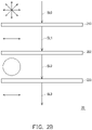
- FIG. 2A is a schematic diagram of a light modulation device according to an embodiment of the disclosure.
- the light modulation device 20 includes a first linear polarizer 210, a phase modulator 201, and a second linear polarizer 220, which are sequentially disposed on the transmission path of an ambient light SL0, SL1, SL2, SL3 (for ease of description, hereinafter referred to as the original ambient light SL0).
- the phase modulator 201 is a quarter wave plate.
- a transmission axis of the first linear polarizer 210 and a slow axis of the quarter wave plate form an included angle, which is greater than 0 degrees and less than 45 degrees.
- An ambient light SL1 passing through the first linear polarizer 210 (hereinafter referred to as part of the ambient light SL1) is a linear polarized light.
- An ambient light SL2 which passes through the phase modulator 201 and is modulated by the phase modulator 201(hereinafter referred to as part of the ambient light SL2) is an elliptical polarized light. Since the part of the ambient light SL2 is an elliptical polarized light, a direction of an absorption axis of the second linear polarizer 220 may be arranged, the second linear polarizer 220 may absorb more than 50% of the light energy of the elliptical polarized light.
- a light energy of a linear polarized ambient light SL3 passing through the second linear polarizer 220 may be less than or equal to 25% of the light energy of the original ambient light SL0.
- FIG. 2B is a schematic diagram of a light modulation device according to an embodiment of the disclosure.
- the light modulation device 20 includes the first linear polarizer 210, a phase modulator 202, and the second linear polarizer 220, which are sequentially disposed on the transmission path of the original ambient light SL0 and part of the ambient light SL1, SL2, SL3.
- the embodiment is the same as the embodiment shown in FIG. 2A in that the phase modulator 202 is a quarter wave plate.
- the embodiment is different from the embodiment shown in FIG. 2A in that the transmission axis of the first linear polarizer 210 and the slow axis of the quarter wave plate form an included angle, which is 45 degrees.
- the part of the ambient light SL2 which passes through the phase modulator 202 and is modulated by the phase modulator 202 is a circular polarized light. After the part of the ambient light SL2 passes through the second linear polarizer 220, the part of the ambient light SL3 is generated. A light energy of the part of the ambient light SL3 is 25% of the light energy of the original ambient light SL0.
- the head up display 1 includes the light modulation device 20 as shown in FIG. 2B .
- the first linear polarizer 210, the phase modulator 202, and the second linear polarizer 220 of the light modulation device 20 are stacked and disposed on the image-light source 10, and the image-light source 10 includes the display device 101 shown in FIG. 1 .
- the display device 101 includes the liquid crystal panel and an upper polarizer (the third linear polarizer).
- the transmission axis of the second linear polarizer 220 of the light modulation device 20 is parallel to a transmission axis of the upper polarizer of the display device 101.
- the transmission axis of the second linear polarizer 220 of the light modulation device 20 is parallel to the transmission axis of the upper polarizer of the display device 101, and is parallel to the transmission axis of the first linear polarizer 210.
- the image light IL has higher transmittance during the process of passing through the light modulation device 20.
- the disclosure is not limited to the aforementioned.
- an included angle among the transmission axis of the first linear polarizer 210, the transmission axis of the second linear polarizer 220, and the transmission axis of the upper polarizer of the display device 101 may be adjusted according to the intensity of the image light IL and the intensity of the ambient light SL.
- the transmission axis of the first linear polarizer 210, the transmission axis of the second linear polarizer 220, and the transmission axis of the upper polarizer of the display device 101 are parallel.
- the image light IL is reflected on the reflective screen 30.
- the image light IL reflected on the surface 301 of the reflective screen 30 is, for example, a first polarization state, that is, the S polarization state, which improves the reflectance of the image light IL and increases the light energy entering the eyes of driver.
- FIG. 2C is a schematic diagram of a light modulation device according to an embodiment of the disclosure.
- the light modulation device 20 includes the first linear polarizer 210, a phase modulator 203, and the second linear polarizer 220, which are sequentially disposed on the transmission path of the original ambient light SL0 and part of the ambient light SL1, SL2, SL3.
- the embodiment is different from the embodiment shown in FIG. 2A in that the phase modulator 203 is a depolarizer, so that the part of the ambient light SL2 passing through the phase modulator 203 is a non-polarized light.
- the part of the ambient light SL3 is generated.
- a light energy of the part of the ambient light SL3 is 25% of the light energy of the original ambient light SL0.
- FIG. 3 is a schematic diagram of a head up display according to another embodiment of the disclosure.
- the head up display 2 is different from the head up display 1 in the embodiment shown in FIG. 1 in that the light modulation device in the head up display 2 is implemented based on the above-described light modulation device 20 shown in FIG. 2A , and that on the transmission path of the image light IL, the reflectors 40 and 50 in the head up display 2 are disposed between the first linear polarizer 210 and the phase modulator 201, the reflectors 40 and 50 are configured to change the transmission direction of the image light IL and reduce the overall volume of the head up display 2.
- the first linear polarizer 210 of the light modulation device 20 is disposed on the dust cover 60.
- the phase modulator 201 and the second linear polarizer 220 of the light modulation device 20 may be adhered together and disposed on the light-emitting surface of the display device 101.
- the disclosure is not limited to the aforementioned.
- the first linear polarizer 210, the phase modulator 201, and the second linear polarizer 220 of the light modulation device 20 may be respectively disposed between the reflective screen 30 and the display device 101.
- the light modulation device 20 When the light modulation device 20 is disposed on the display device 101, the light modulation device 20 may be fixed by an adhesion method or a mechanism (frame) without the necessity of directly contacting the display device 101, and a distance is kept between the display device 101 and the light modulation device 20.
- the first linear polarizer 210 and the phase modulator 201 of the light modulation device 20 may be disposed on the dust cover 60, and the second linear polarizer 220 is disposed on the light-emitting surface of the display device 101.
- the elements of the light modulation device 20 are all disposed on the dust cover 60.
- the head up display modulates an ambient light by using a light modulation device to change the optical characteristics of the ambient light in order to reduce a light energy entering the head up display and to prevent the head up display from being damaged by long-term exposure to the ambient light.
- the term "the invention”, “the present invention” or the like does not necessarily limit the claim scope to a specific embodiment, and the reference to particularly preferred exemplary embodiments of the invention does not imply a limitation on the invention, and no such limitation is to be inferred.
- the invention is limited only by the scope of the appended claims. Moreover, these claims may refer to use "first”, “second”, etc. following with noun or element. Such terms should be understood as a nomenclature and should not be construed as giving the limitation on the number of the elements modified by such nomenclature unless specific number has been given.
- the abstract of the disclosure is provided to comply with the rules requiring an abstract, which will allow a searcher to quickly ascertain the subject matter of the technical disclosure of any patent issued from this disclosure.
Landscapes
- Physics & Mathematics (AREA)
- General Physics & Mathematics (AREA)
- Optics & Photonics (AREA)
- Nonlinear Science (AREA)
- Mathematical Physics (AREA)
- Chemical & Material Sciences (AREA)
- Crystallography & Structural Chemistry (AREA)
- Instrument Panels (AREA)
Abstract
Description
- This application claims the priority benefits of
US provisional application serial no. 63/222,452, filed on July 16, 2021 China application serial no. 202111346454.0, filed on November 15, 2021 - The disclosure relates to a head up display.
- The development of display technology in recent years has driven a large number of head up displays to be used in life. In particular, head up displays presenting information superimposed on environmental images are often used in airplanes, vehicles, and shop windows. Taking a head up display for a vehicle as an example, the head up display uses the inner surface of the windshield as an optical combiner to provide the driver with information. Therefore, when driving, the driver may see the information provided by an in-vehicle information system without looking down at the dashboard or navigator.
- Since head up displays are mostly used outdoors, sunlight converges to the internal display panel through the imaging lenses of the head up display, which may cause the internal temperature to be above the upper limit (about 100 degrees to 110 degrees) that the display panel may withstand. Generally, the light energy density of sunlight is 1050 W/m2. When sunlight converges to a small area of the display panel, the light energy density will be higher than 20000 W/m2 to 60000 W/m2, resulting in the temperature of the display panel being above 105 degrees. Such a temperature may cause damage to the display panel and reduce the service life of the head up display. Therefore, there is an urgent need to develop a technology that may prevent a large amount of sunlight from entering a head up display.
- The information disclosed in this Background section is only for enhancement of understanding of the background of the described technology and therefore it may contain information that does not form the prior art that is already known to a person of ordinary skill in the art. Further, the information disclosed in the Background section does not mean that one or more problems to be resolved by one or more embodiments of the invention was acknowledged by a person of ordinary skill in the art.
- It is an object to provide a head up display, which may prevent a large amount of ambient light from entering the head up display, and prevent the head up display from being damaged by long-term exposure to the ambient light.
- The object is solved by the features of the independent claims. Preferred embodiments are given in the dependent claims.
- According to an embodiment of the disclosure, a head up display is provided, and the head up display includes an image-light source, at least one reflector, and a light modulation device. The image-light source is configured to provide an image light. The at least one reflector is configured to transmit the image light to leave the head up display. The light modulation device is disposed on the transmission path of the image light, and is disposed in the head up display. An ambient light enters the image-light source after passing through the light modulation device, and a light energy of the ambient light entering the image-light source is less than or equal to 25% of a light energy of the ambient light entering the head up display.
- In an embodiment, when the ambient light is transmitted through the light modulation device to the image-light source, a polarization state of the ambient light may include a linear polarization state and an elliptical polarization state, may include a linear polarization state and a circular polarization state, or may include a linear polarization state and a non-polarized state.
- In an embodiment, the light modulation device may include a first linear polarizer, a phase modulator, and a second linear polarizer.
- In one or more embodiments the first linear polarizer, the phase modulator, and the second linear polarizer may be sequentially disposed on the transmission path of the ambient light entering the image-light source.
- In an embodiment, the phase modulator may be a quarter wave plate.
- In an embodiment, a transmission axis of the first linear polarizer and the slow axis of the quarter wave plate may form an included angle.
- In an embodiment, the phase modulator may be a depolarizer.
- In an embodiment, the image-light source further may include a display device.
- In one or more embodiments, the display device may include a liquid crystal panel and a third linear polarizer.
- A transmission axis of the second linear polarizer may be parallel to a transmission axis of the third linear polarizer.
- In an embodiment, the transmission axis of the first linear polarizer may be parallel to the transmission axis of the second linear polarizer.
- In an embodiment, the image light leaving the head up display may be transmitted to a reflective screen.
- In one or more embodiments, the image light may be reflected on the reflective screen to enter eyes.
- The image light may be reflected on the reflective screen after passing through the first linear polarizer.
- A polarization state of the image light reflected on the reflective screen may be a first polarization state.
- In an embodiment, a dust cover may be further included.
- The dust cover may be disposed between the reflective screen and the image-light source.
- The dust cover may be configured to prevent dust from falling into the head up display.
- In an embodiment, on the transmission path of the ambient light, the first linear polarizer of the light modulation device may be disposed on the dust cover.
- The phase modulator and the second linear polarizer may be disposed on a display device of the image-light source.
- Based on the aforementioned, the head up display provided by the embodiments of the disclosure modulates the ambient light to change the optical characteristics of the ambient light by using the light modulation device, so as to reduce a light energy entering the head up display and prevent the head up display from being damaged by long-term exposure to the ambient light.
- In order to make the aforementioned features and advantages of the disclosure more comprehensible, embodiments accompanied with drawings are specifically described in detail as follows.
- Other objectives, features and advantages of the present invention will be further understood from the further technological features disclosed by the embodiments of the present invention wherein there are shown and described preferred embodiments of this invention, simply by way of illustration of modes best suited to carry out the invention.
- The accompanying drawings are included to provide a further understanding of the invention, and are incorporated in and constitute a part of this specification. The drawings illustrate embodiments of the invention and, together with the description, serve to explain the principles of the invention.
-
FIG. 1 is a schematic diagram of a head up display according to an embodiment of the disclosure. -
FIG. 2A ,FIG. 2B , andFIG. 2C are schematic diagrams of a light modulation device according to embodiments of the disclosure. -
FIG. 3 is a schematic diagram of a head up display according to another embodiment of the disclosure. - In the following detailed description of the preferred embodiments, reference is made to the accompanying drawings which form a part hereof, and in which are shown by way of illustration specific embodiments in which the invention may be practiced. In this regard, directional terminology, such as "top," "bottom," "front," "back," etc., is used with reference to the orientation of the Figure(s) being described. The components of the present invention can be positioned in a number of different orientations. As such, the directional terminology is used for purposes of illustration and is in no way limiting. On the other hand, the drawings are only schematic and the sizes of components may be exaggerated for clarity. It is to be understood that other embodiments may be utilized and structural changes may be made without departing from the scope of the present invention. Also, it is to be understood that the phraseology and terminology used herein are for the purpose of description and should not be regarded as limiting. The use of "including," "comprising," or "having" and variations thereof herein is meant to encompass the items listed thereafter and equivalents thereof as well as additional items. Unless limited otherwise, the terms "connected," "coupled," and "mounted" and variations thereof herein are used broadly and encompass direct and indirect connections, couplings, and mountings. Similarly, the terms "facing," "faces" and variations thereof herein are used broadly and encompass direct and indirect facing, and "adjacent to" and variations thereof herein are used broadly and encompass directly and indirectly "adjacent to". Therefore, the description of "A" component facing "B" component herein may contain the situations that "A" component directly faces "B" component or one or more additional components are between "A" component and "B" component. Also, the description of "A" component "adjacent to" "B" component herein may contain the situations that "A" component is directly "adjacent to" "B" component or one or more additional components are between "A" component and "B" component. Accordingly, the drawings and descriptions will be regarded as illustrative in nature and not as restrictive.
- The foregoing and other technical content, features, and effects of the disclosure are clearly presented in the following detailed description of a preferred embodiment with reference to the accompanying drawings. Directional terms such as top, bottom, left, right, front or back, etc. mentioned in the following embodiments are only directions for referring to the accompanying drawings. Therefore, the directional terms used are for illustration rather than limitation of the disclosure.
- Please refer to
FIG. 1, FIG. 1 is a schematic diagram of a head up display according to an embodiment of the disclosure. The head updisplay 1 includes an image-light source 10, alight modulation device 20, and at least one reflector (40 and 50). The image-light source 10 includes adisplay device 101. Thedisplay device 101 includes a liquid crystal panel. The image-light source 10 is configured to provide an image light IL. Through the at least one reflector (40 and 50), the image light IL is transmitted to asurface 301 of areflective screen 30 and is reflected to eyes of user. On the transmission path of the image light IL, the at least one reflector (40 and 50) is disposed between the image-light source 10 and the eyes. Thelight modulation device 20 is disposed in the head updisplay 1. - In other embodiments, a head up
display 1 includes an image-light source 10, alight modulation device 20, and asingle reflector light source 10 is configured to provide an image light IL. Through thesingle reflector reflective screen 30 and is reflected to eyes of user. Thereflector - In one embodiment, a head up
display 1 is implemented as the head up display for a vehicle, and areflective screen 30 is implemented as a windshield. In addition, the head updisplay 1 further includes adust cover 60. Thesurface 301 of thereflective screen 30 corresponds to the surface of the windshield inside the vehicle, and thesurface 30J corresponds to the surface of the windshield outside the vehicle. The image light IL enters the eyes of the driver after being reflected on the surface of the windshield inside the vehicle, and the image light IL entering the eyes forms a virtual image in front of the eyes of driver. Thedust cover 60 is, for example, a transparent plastic cover, and the material of thedust cover 60 is, for example, polyethylene terephthalate (PET). The dust cover is configured to prevent dust from falling into the head updisplay 1, that is, the dust may not touch the image-light source 10, thelight modulation device 20, and thesingle reflector light modulation device 20 is disposed between the image-light source 10 and thedust cover 60. - To prevent a large amount of ambient light (such as sunlight) from entering the head up
display 1, and causing thedisplay device 101 to be damaged due to high temperature. On the transmission path of the image light IL, thelight modulation device 20 of the head updisplay 1 is disposed between the image-light source 10 and thereflective screen 30. Thelight modulation device 20 is configured to modulate the phase and polarization state of an incident light, and then a polarization selection element is configured to select a specific polarization state so as to reduce a light energy of the light passing through thelight modulation device 20. In the embodiment shown inFIG. 1 , on the transmission path of the image light IL, thelight modulation device 20 is disposed between thedisplay device 101 and thereflector light modulation device 20. Thus, the light energy of the ambient light SL entering the image-light source 10 is less than or equal to (≦) 25% of the light energy of the ambient light SL entering the head updisplay 1, thereby reducing the temperature raised by the ambient light SL irradiating thedisplay device 101. - In an embodiment of the disclosure, a
light modulation device 20 is, for example, a sun light filter (SLF). Thelight modulation device 20 includes a first linear polarizer, a phase modulator, and a second linear polarizer, which are sequentially disposed on the transmission path of an ambient light SL entering an image-light source 10. The ambient light SL is non-polarized light. It should be noted that non-polarized light is not a light without a polarization direction, but the polarization direction changes very quickly with time. After the ambient light SL passes through the first linear polarizer, part of the ambient light SL of which polarization direction is parallel to an absorption axis of the first linear polarizer is absorbed by the first linear polarizer, and the part of the ambient light SL passing through the first linear polarizer is a linear polarized light. The polarized light may be S-polarized light or P-polarized light. In general, a light energy of the part of the ambient light SL absorbed as mentioned above accounts for about 50% of a light energy of the original ambient light SL. In other words, the light energy of the part of the ambient light SL passing through the first linear polarizer accounts for about 50% of the light energy of the original ambient light SL. The phase modulator is disposed between the first linear polarizer and the second linear polarizer. The phase modulator is configured to modulate the phase of the part of the ambient light SL passing through the first linear polarizer, so that the polarization state of the part of the ambient light SL is changed from linear polarization to other polarization states, such as circular polarized light, elliptical polarized light, or non-polarized light. After that, by appropriately arranging a direction of an absorption axis of the second linear polarizer, 50% of the light energy of the part of the ambient light SL is absorbed again. Therefore, a light energy of the part of the ambient light SL passing through thelight modulation device 20 is less than or equal to 25% of the light energy of the original ambient light SL. Referring to various embodiments of the disclosure, how a light modulation device reduces a light energy of an ambient light entering a head updisplay 1 is specifically described in the following. - Please refer to
FIG. 2A, FIG. 2A is a schematic diagram of a light modulation device according to an embodiment of the disclosure. Thelight modulation device 20 includes a firstlinear polarizer 210, aphase modulator 201, and a secondlinear polarizer 220, which are sequentially disposed on the transmission path of an ambient light SL0, SL1, SL2, SL3 (for ease of description, hereinafter referred to as the original ambient light SL0). In the embodiment, thephase modulator 201 is a quarter wave plate. In addition, a transmission axis of the firstlinear polarizer 210 and a slow axis of the quarter wave plate form an included angle, which is greater than 0 degrees and less than 45 degrees. An ambient light SL1 passing through the first linear polarizer 210 (hereinafter referred to as part of the ambient light SL1) is a linear polarized light. An ambient light SL2 which passes through thephase modulator 201 and is modulated by the phase modulator 201(hereinafter referred to as part of the ambient light SL2) is an elliptical polarized light. Since the part of the ambient light SL2 is an elliptical polarized light, a direction of an absorption axis of the secondlinear polarizer 220 may be arranged, the secondlinear polarizer 220 may absorb more than 50% of the light energy of the elliptical polarized light. In this case, a light energy of a linear polarized ambient light SL3 passing through the second linear polarizer 220 (hereinafter referred to as part of the ambient light SL3) may be less than or equal to 25% of the light energy of the original ambient light SL0. - Please refer to
FIG. 2B, FIG. 2B is a schematic diagram of a light modulation device according to an embodiment of the disclosure. Thelight modulation device 20 includes the firstlinear polarizer 210, aphase modulator 202, and the secondlinear polarizer 220, which are sequentially disposed on the transmission path of the original ambient light SL0 and part of the ambient light SL1, SL2, SL3. The embodiment is the same as the embodiment shown inFIG. 2A in that thephase modulator 202 is a quarter wave plate. The embodiment is different from the embodiment shown inFIG. 2A in that the transmission axis of the firstlinear polarizer 210 and the slow axis of the quarter wave plate form an included angle, which is 45 degrees. The part of the ambient light SL2 which passes through thephase modulator 202 and is modulated by thephase modulator 202 is a circular polarized light. After the part of the ambient light SL2 passes through the secondlinear polarizer 220, the part of the ambient light SL3 is generated. A light energy of the part of the ambient light SL3 is 25% of the light energy of the original ambient light SL0. - Please refer to
FIG. 1 andFIG. 2B at the same time. In an embodiment of the disclosure, the head updisplay 1 includes thelight modulation device 20 as shown inFIG. 2B . The firstlinear polarizer 210, thephase modulator 202, and the secondlinear polarizer 220 of thelight modulation device 20 are stacked and disposed on the image-light source 10, and the image-light source 10 includes thedisplay device 101 shown inFIG. 1 . Thedisplay device 101 includes the liquid crystal panel and an upper polarizer (the third linear polarizer). The transmission axis of the secondlinear polarizer 220 of thelight modulation device 20 is parallel to a transmission axis of the upper polarizer of thedisplay device 101. As a result, during the process of passing through thelight modulation device 20, the image light IL has higher transmittance without being absorbed. - In another embodiment of the disclosure, the transmission axis of the second
linear polarizer 220 of thelight modulation device 20 is parallel to the transmission axis of the upper polarizer of thedisplay device 101, and is parallel to the transmission axis of the firstlinear polarizer 210. As a result, the image light IL has higher transmittance during the process of passing through thelight modulation device 20. However, the disclosure is not limited to the aforementioned. In some embodiments of the disclosure, an included angle among the transmission axis of the firstlinear polarizer 210, the transmission axis of the secondlinear polarizer 220, and the transmission axis of the upper polarizer of thedisplay device 101 may be adjusted according to the intensity of the image light IL and the intensity of the ambient light SL. - In yet another embodiment of the disclosure, the transmission axis of the first
linear polarizer 210, the transmission axis of the secondlinear polarizer 220, and the transmission axis of the upper polarizer of thedisplay device 101 are parallel. After passing through the firstlinear polarizer 210, the image light IL is reflected on thereflective screen 30. The image light IL reflected on thesurface 301 of thereflective screen 30 is, for example, a first polarization state, that is, the S polarization state, which improves the reflectance of the image light IL and increases the light energy entering the eyes of driver. - Please refer to
FIG. 2C, FIG. 2C is a schematic diagram of a light modulation device according to an embodiment of the disclosure. Thelight modulation device 20 includes the firstlinear polarizer 210, aphase modulator 203, and the secondlinear polarizer 220, which are sequentially disposed on the transmission path of the original ambient light SL0 and part of the ambient light SL1, SL2, SL3. The embodiment is different from the embodiment shown inFIG. 2A in that thephase modulator 203 is a depolarizer, so that the part of the ambient light SL2 passing through thephase modulator 203 is a non-polarized light. After the part of the ambient light SL2 passes through the secondlinear polarizer 220, the part of the ambient light SL3 is generated. A light energy of the part of the ambient light SL3 is 25% of the light energy of the original ambient light SL0. - Please refer to
FIG. 3, FIG. 3 is a schematic diagram of a head up display according to another embodiment of the disclosure. The head updisplay 2 is different from the head updisplay 1 in the embodiment shown inFIG. 1 in that the light modulation device in the head updisplay 2 is implemented based on the above-describedlight modulation device 20 shown inFIG. 2A , and that on the transmission path of the image light IL, thereflectors display 2 are disposed between the firstlinear polarizer 210 and thephase modulator 201, thereflectors display 2. The firstlinear polarizer 210 of thelight modulation device 20 is disposed on thedust cover 60. Thephase modulator 201 and the secondlinear polarizer 220 of thelight modulation device 20 may be adhered together and disposed on the light-emitting surface of thedisplay device 101. However, the disclosure is not limited to the aforementioned. In an unshown embodiment of the disclosure, on the transmission path of the ambient light SL, the firstlinear polarizer 210, thephase modulator 201, and the secondlinear polarizer 220 of thelight modulation device 20 may be respectively disposed between thereflective screen 30 and thedisplay device 101. When thelight modulation device 20 is disposed on thedisplay device 101, thelight modulation device 20 may be fixed by an adhesion method or a mechanism (frame) without the necessity of directly contacting thedisplay device 101, and a distance is kept between thedisplay device 101 and thelight modulation device 20. In other embodiments, the firstlinear polarizer 210 and thephase modulator 201 of thelight modulation device 20 may be disposed on thedust cover 60, and the secondlinear polarizer 220 is disposed on the light-emitting surface of thedisplay device 101. In another embodiment, the elements of thelight modulation device 20 are all disposed on thedust cover 60. - In summary, the head up display provided by the embodiments of the disclosure modulates an ambient light by using a light modulation device to change the optical characteristics of the ambient light in order to reduce a light energy entering the head up display and to prevent the head up display from being damaged by long-term exposure to the ambient light.
- However, the aforementioned are merely exemplary embodiments of the disclosure, and should not be used to limit the scope of implementation of the disclosure, that is, simple equivalent changes and modifications made in accordance with the scope of the claims of the disclosure and the description of the disclosure are all still within the scope of the disclosure. In addition, any embodiment or claim of the disclosure does not have to achieve all the objectives or advantages or features disclosed in the disclosure. Moreover, the abstract and the title are only used to assist the search of patent documents rather than being used to limit the claims of the disclosure. Furthermore, the terms "first" and "second" mentioned in this specification or the claims are merely used to name elements or to distinguish different embodiments or scopes rather than being used to limit the upper or lower limit of the number of the elements.
- The foregoing description of the preferred embodiments of the invention has been presented for purposes of illustration and description. It is not intended to be exhaustive or to limit the invention to the precise form or to exemplary embodiments disclosed. Accordingly, the foregoing description should be regarded as illustrative rather than restrictive. Obviously, many modifications and variations will be apparent to practitioners skilled in this art. The embodiments are chosen and described in order to best explain the principles of the invention and its best mode practical application, thereby to enable persons skilled in the art to understand the invention for various embodiments and with various modifications as are suited to the particular use or implementation contemplated. It is intended that the scope of the invention be defined by the claims appended hereto and their equivalents in which all terms are meant in their broadest reasonable sense unless otherwise indicated. Therefore, the term "the invention", "the present invention" or the like does not necessarily limit the claim scope to a specific embodiment, and the reference to particularly preferred exemplary embodiments of the invention does not imply a limitation on the invention, and no such limitation is to be inferred. The invention is limited only by the scope of the appended claims. Moreover, these claims may refer to use "first", "second", etc. following with noun or element. Such terms should be understood as a nomenclature and should not be construed as giving the limitation on the number of the elements modified by such nomenclature unless specific number has been given. The abstract of the disclosure is provided to comply with the rules requiring an abstract, which will allow a searcher to quickly ascertain the subject matter of the technical disclosure of any patent issued from this disclosure. It is submitted with the understanding that it will not be used to interpret or limit the scope or meaning of the claims. Any advantages and benefits described may not apply to all embodiments of the invention. It should be appreciated that variations may be made in the embodiments described by persons skilled in the art without departing from the scope of the present invention as defined by the following claims. Moreover, no element and component in the present disclosure is intended to be dedicated to the public regardless of whether the element or component is explicitly recited in the following claims.
Claims (12)
- A head up display, comprising:an image-light source, configured to provide an image light;at least one reflector, configured to transmit the image light to leave the head up display; anda light modulation device, disposed in the head up display, and disposed on a transmission path of the image light,wherein an ambient light enters the image-light source after passing through the light modulation device, and a light energy of the ambient light entering the image-light source is less than or equal to 25% of a light energy of the ambient light entering the head up display.
- The head up display according to claim 1, wherein when the ambient light is transmitted through the light modulation device to the image-light source, a polarization state of the ambient light comprises a linear polarization state and an elliptical polarization state, comprises a linear polarization state and a circular polarization state, or comprises a linear polarization state and a non-polarized state.
- The head up display according to claim 1 or 2, wherein the light modulation device comprises a first linear polarizer, a phase modulator, and a second linear polarizer.
- The head up display according to claim 3, wherein the first linear polarizer, the phase modulator, and the second linear polarizer are sequentially disposed on a transmission path of the ambient light entering the image-light source.
- The head up display according to claim 3 or 4, wherein the phase modulator is a quarter wave plate.
- The head up display according to claim 3, 4 or 5, wherein a transmission axis of the first linear polarizer and a slow axis of the quarter wave plate form an included angle.
- The head up display according to claim 3 or 4, wherein the phase modulator is a depolarizer.
- The head up display according to any one of the claims 3-6, wherein the image-light source further comprises a display device, and the display device comprises a liquid crystal panel and a third linear polarizer, and a transmission axis of the second linear polarizer is parallel to a transmission axis of the third linear polarizer.
- The head up display according to claim 8, wherein a transmission axis of the first linear polarizer is parallel to the transmission axis of the second linear polarizer.
- The head up display according to any one of the claims 3-9, wherein the image light leaving the head up display is transmitted to a reflective screen, and the image light is reflected on the reflective screen to enter eyes, wherein the image light is reflected on the reflective screen after passing through the first linear polarizer, and a polarization state of the image light reflected on the reflective screen is a first polarization state.
- The head up display according to claim 10, further comprising a dust cover, disposed between the reflective screen and the image-light source, the dust cover is configured to prevent dust from falling into the head up display.
- The head up display according to claim 11, wherein on the transmission path of the ambient light, the first linear polarizer of the light modulation device is disposed on the dust cover, and the phase modulator and the second linear polarizer are disposed on a display device of the image-light source.
Applications Claiming Priority (2)
| Application Number | Priority Date | Filing Date | Title |
|---|---|---|---|
| US202163222452P | 2021-07-16 | 2021-07-16 | |
| CN202111346454.0A CN115616775A (en) | 2021-07-16 | 2021-11-15 | Head-up display |
Publications (1)
| Publication Number | Publication Date |
|---|---|
| EP4120004A1 true EP4120004A1 (en) | 2023-01-18 |
Family
ID=82020867
Family Applications (1)
| Application Number | Title | Priority Date | Filing Date |
|---|---|---|---|
| EP22178621.3A Pending EP4120004A1 (en) | 2021-07-16 | 2022-06-13 | Head up display |
Country Status (4)
| Country | Link |
|---|---|
| US (1) | US11988830B2 (en) |
| EP (1) | EP4120004A1 (en) |
| JP (1) | JP2023013968A (en) |
| KR (1) | KR20230012984A (en) |
Citations (5)
| Publication number | Priority date | Publication date | Assignee | Title |
|---|---|---|---|---|
| DE102005020233A1 (en) * | 2005-04-30 | 2006-11-09 | Carl Zeiss Jena Gmbh | Head-up display (HUD) for vehicles has linear polarizer that is arranged such that absorption of light whose E-vector is s-polarized is minimized |
| US20120105808A1 (en) * | 2010-10-28 | 2012-05-03 | Gm Global Technology Operations, Inc. | Vehicle display system |
| US20190258059A1 (en) * | 2018-02-21 | 2019-08-22 | Yazaki Corporation | Vehicular display device |
| US20200026073A1 (en) * | 2016-09-22 | 2020-01-23 | Denso Corporation | Head-up display device |
| JP2020144306A (en) * | 2019-03-08 | 2020-09-10 | マクセル株式会社 | Head-up display device |
Family Cites Families (26)
| Publication number | Priority date | Publication date | Assignee | Title |
|---|---|---|---|---|
| JP6135048B2 (en) | 2012-04-24 | 2017-05-31 | 日本精機株式会社 | Head-up display device |
| JP6056246B2 (en) | 2012-07-30 | 2017-01-11 | 株式会社Jvcケンウッド | Image display device |
| JP6234339B2 (en) | 2014-07-25 | 2017-11-22 | カルソニックカンセイ株式会社 | Head-up display device for vehicle |
| DE102015222842A1 (en) | 2015-11-19 | 2017-05-24 | Robert Bosch Gmbh | Cover element for covering a projection opening of a head-up display, head-up display and method for passing light through a cover |
| WO2017094248A1 (en) * | 2015-12-01 | 2017-06-08 | パナソニックIpマネジメント株式会社 | Free-form surface lens and head-up display |
| JP6320645B2 (en) | 2016-05-16 | 2018-05-09 | 株式会社ポラテクノ | Polarizing member and head-up display device including the same |
| CN109790959A (en) * | 2016-10-04 | 2019-05-21 | 麦克赛尔株式会社 | Light supply apparatus and head-up display |
| WO2018155958A1 (en) * | 2017-02-23 | 2018-08-30 | 엘지전자 주식회사 | Head-up display for vehicle |
| JP7025439B2 (en) | 2017-03-03 | 2022-02-24 | オステンド・テクノロジーズ・インコーポレーテッド | Split exit pupil head-up display system and method |
| DE102017206805A1 (en) * | 2017-04-24 | 2018-10-25 | Continental Automotive Gmbh | Head-Up Display |
| JP6911114B2 (en) * | 2017-06-16 | 2021-07-28 | マクセル株式会社 | Light source device and head-up display device |
| CN108061968B (en) | 2018-01-05 | 2021-10-15 | 京东方科技集团股份有限公司 | Head-up display device and display image correction method |
| KR102570280B1 (en) | 2018-01-30 | 2023-08-24 | 삼성전자주식회사 | Appratus for providing head-up diplay image |
| EP3525038A1 (en) | 2018-02-12 | 2019-08-14 | Visteon Global Technologies, Inc. | Display arrangement and method of controlling a display arrangement |
| CN108919496A (en) | 2018-08-08 | 2018-11-30 | 京东方科技集团股份有限公司 | The low-power consumption HUD system of solar radiation protection |
| JP2020118826A (en) | 2019-01-23 | 2020-08-06 | 日東電工株式会社 | Head-up display device and manufacturing method therefor |
| CN112444982A (en) | 2019-09-02 | 2021-03-05 | 未来(北京)黑科技有限公司 | Head-up display device |
| CN110908124A (en) | 2019-12-23 | 2020-03-24 | 浙江水晶光电科技股份有限公司 | HUD light path system, control method thereof and HUD display device |
| JP2021179563A (en) * | 2020-05-15 | 2021-11-18 | 株式会社ジャパンディスプレイ | Display unit |
| CN114063291A (en) | 2020-08-07 | 2022-02-18 | 未来(北京)黑科技有限公司 | Head-up display device, head-up display system and traffic equipment |
| GB2600109B (en) * | 2020-10-20 | 2024-08-07 | Envisics Ltd | Display system and method |
| KR102480506B1 (en) | 2020-10-21 | 2022-12-22 | 현대모비스 주식회사 | Method And Apparatus for Releasing HUD Protection Mode Based on Vehicle Information |
| CN112255810A (en) | 2020-12-14 | 2021-01-22 | 深圳市锐思华创技术有限公司 | Anti-sun glare head-up display optical system based on small inclination angle |
| CN112835198A (en) | 2021-03-04 | 2021-05-25 | 浙江水晶光电科技股份有限公司 | Optical module for head-up display, optical system and vehicle thereof |
| CN114077065A (en) | 2021-12-15 | 2022-02-22 | 浙江水晶光电科技股份有限公司 | Optical module and head-up display |
| JP2023171303A (en) | 2022-05-20 | 2023-12-01 | 中強光電股▲ふん▼有限公司 | Head-up display |
-
2022
- 2022-06-13 EP EP22178621.3A patent/EP4120004A1/en active Pending
- 2022-06-13 US US17/838,274 patent/US11988830B2/en active Active
- 2022-06-15 JP JP2022096418A patent/JP2023013968A/en active Pending
- 2022-07-11 KR KR1020220085175A patent/KR20230012984A/en unknown
Patent Citations (5)
| Publication number | Priority date | Publication date | Assignee | Title |
|---|---|---|---|---|
| DE102005020233A1 (en) * | 2005-04-30 | 2006-11-09 | Carl Zeiss Jena Gmbh | Head-up display (HUD) for vehicles has linear polarizer that is arranged such that absorption of light whose E-vector is s-polarized is minimized |
| US20120105808A1 (en) * | 2010-10-28 | 2012-05-03 | Gm Global Technology Operations, Inc. | Vehicle display system |
| US20200026073A1 (en) * | 2016-09-22 | 2020-01-23 | Denso Corporation | Head-up display device |
| US20190258059A1 (en) * | 2018-02-21 | 2019-08-22 | Yazaki Corporation | Vehicular display device |
| JP2020144306A (en) * | 2019-03-08 | 2020-09-10 | マクセル株式会社 | Head-up display device |
Non-Patent Citations (1)
| Title |
|---|
| ANONYMOUS: "Liquid-crystal display - Wikipedia", 5 February 2021 (2021-02-05), pages 1 - 34, XP055981790, Retrieved from the Internet <URL:https://web.archive.org/web/20210205132316/https://en.wikipedia.org/wiki/Liquid-crystal_display> [retrieved on 20221115] * |
Also Published As
| Publication number | Publication date |
|---|---|
| US11988830B2 (en) | 2024-05-21 |
| JP2023013968A (en) | 2023-01-26 |
| US20230025573A1 (en) | 2023-01-26 |
| KR20230012984A (en) | 2023-01-26 |
Similar Documents
| Publication | Publication Date | Title |
|---|---|---|
| US6961108B2 (en) | Liquid crystal display viewable under all lighting conditions | |
| US5157526A (en) | Unabsorbing type polarizer, method for manufacturing the same, polarized light source using the same, and apparatus for liquid crystal display using the same | |
| US10591722B2 (en) | Display system and transflective optical plate | |
| JP2000131682A (en) | Display device | |
| US11453340B2 (en) | Display device | |
| US9637054B2 (en) | Switchable rearview mirror element with anti-reflection mechanisms for use with a display | |
| CN103576374B (en) | Liquid crystal indicator | |
| US10444500B2 (en) | Projection screen of head-up display | |
| JPH06885U (en) | Vehicle display | |
| US20230375821A1 (en) | Head up display device | |
| EP4120004A1 (en) | Head up display | |
| US20060077325A1 (en) | Cholesteric liquid crystal light control film | |
| JPH113608A (en) | Method for illuminating display element, and liquid crystal display device | |
| JPH0854612A (en) | Liquid crystal display | |
| CN110989173A (en) | Display system | |
| CN216210293U (en) | Polaroid structure for sunglasses and polarized sunglasses | |
| US8405895B2 (en) | Optical system with high contrast | |
| TWI818354B (en) | Head up display | |
| KR20030003687A (en) | Lquid crystal projector | |
| CN208429022U (en) | A kind of vehicular rear mirror | |
| CN108873475B (en) | Reflective liquid crystal display panel, preparation method thereof and display device | |
| CN108169952B (en) | Anti-dazzle rearview mirror and control method thereof | |
| CN220894663U (en) | Head-up display | |
| CN219856986U (en) | Electronic rearview mirror | |
| CN216979429U (en) | Head-up display device |
Legal Events
| Date | Code | Title | Description |
|---|---|---|---|
| PUAI | Public reference made under article 153(3) epc to a published international application that has entered the european phase |
Free format text: ORIGINAL CODE: 0009012 |
|
| STAA | Information on the status of an ep patent application or granted ep patent |
Free format text: STATUS: THE APPLICATION HAS BEEN PUBLISHED |
|
| AK | Designated contracting states |
Kind code of ref document: A1 Designated state(s): AL AT BE BG CH CY CZ DE DK EE ES FI FR GB GR HR HU IE IS IT LI LT LU LV MC MK MT NL NO PL PT RO RS SE SI SK SM TR |
|
| STAA | Information on the status of an ep patent application or granted ep patent |
Free format text: STATUS: REQUEST FOR EXAMINATION WAS MADE |
|
| 17P | Request for examination filed |
Effective date: 20230718 |
|
| RBV | Designated contracting states (corrected) |
Designated state(s): AL AT BE BG CH CY CZ DE DK EE ES FI FR GB GR HR HU IE IS IT LI LT LU LV MC MK MT NL NO PL PT RO RS SE SI SK SM TR |
|
| GRAP | Despatch of communication of intention to grant a patent |
Free format text: ORIGINAL CODE: EPIDOSNIGR1 |
|
| STAA | Information on the status of an ep patent application or granted ep patent |
Free format text: STATUS: GRANT OF PATENT IS INTENDED |