EP4119929B1 - Verfahren und vorrichtung zur kraftanwendung auf eine probe unter verwendung optischer abfragetechnik - Google Patents
Verfahren und vorrichtung zur kraftanwendung auf eine probe unter verwendung optischer abfragetechnik Download PDFInfo
- Publication number
- EP4119929B1 EP4119929B1 EP22184914.4A EP22184914A EP4119929B1 EP 4119929 B1 EP4119929 B1 EP 4119929B1 EP 22184914 A EP22184914 A EP 22184914A EP 4119929 B1 EP4119929 B1 EP 4119929B1
- Authority
- EP
- European Patent Office
- Prior art keywords
- sample
- force
- reflective element
- internally reflective
- contact member
- Prior art date
- Legal status (The legal status is an assumption and is not a legal conclusion. Google has not performed a legal analysis and makes no representation as to the accuracy of the status listed.)
- Active
Links
Images


Classifications
-
- G—PHYSICS
- G01—MEASURING; TESTING
- G01N—INVESTIGATING OR ANALYSING MATERIALS BY DETERMINING THEIR CHEMICAL OR PHYSICAL PROPERTIES
- G01N21/00—Investigating or analysing materials by the use of optical means, i.e. using sub-millimetre waves, infrared, visible or ultraviolet light
- G01N21/17—Systems in which incident light is modified in accordance with the properties of the material investigated
- G01N21/55—Specular reflectivity
- G01N21/552—Attenuated total reflection
-
- G—PHYSICS
- G01—MEASURING; TESTING
- G01L—MEASURING FORCE, STRESS, TORQUE, WORK, MECHANICAL POWER, MECHANICAL EFFICIENCY, OR FLUID PRESSURE
- G01L1/00—Measuring force or stress, in general
- G01L1/20—Measuring force or stress, in general by measuring variations in ohmic resistance of solid materials or of electrically-conductive fluids; by making use of electrokinetic cells, i.e. liquid-containing cells wherein an electrical potential is produced or varied upon the application of stress
- G01L1/22—Measuring force or stress, in general by measuring variations in ohmic resistance of solid materials or of electrically-conductive fluids; by making use of electrokinetic cells, i.e. liquid-containing cells wherein an electrical potential is produced or varied upon the application of stress using resistance strain gauges
-
- G—PHYSICS
- G01—MEASURING; TESTING
- G01L—MEASURING FORCE, STRESS, TORQUE, WORK, MECHANICAL POWER, MECHANICAL EFFICIENCY, OR FLUID PRESSURE
- G01L5/00—Apparatus for, or methods of, measuring force, work, mechanical power, or torque, specially adapted for specific purposes
- G01L5/0028—Force sensors associated with force applying means
- G01L5/0038—Force sensors associated with force applying means applying a pushing force
-
- G—PHYSICS
- G01—MEASURING; TESTING
- G01N—INVESTIGATING OR ANALYSING MATERIALS BY DETERMINING THEIR CHEMICAL OR PHYSICAL PROPERTIES
- G01N21/00—Investigating or analysing materials by the use of optical means, i.e. using sub-millimetre waves, infrared, visible or ultraviolet light
- G01N21/01—Arrangements or apparatus for facilitating the optical investigation
-
- G—PHYSICS
- G01—MEASURING; TESTING
- G01N—INVESTIGATING OR ANALYSING MATERIALS BY DETERMINING THEIR CHEMICAL OR PHYSICAL PROPERTIES
- G01N21/00—Investigating or analysing materials by the use of optical means, i.e. using sub-millimetre waves, infrared, visible or ultraviolet light
- G01N21/17—Systems in which incident light is modified in accordance with the properties of the material investigated
- G01N21/25—Colour; Spectral properties, i.e. comparison of effect of material on the light at two or more different wavelengths or wavelength bands
- G01N21/255—Details, e.g. use of specially adapted sources, lighting or optical systems
-
- G—PHYSICS
- G01—MEASURING; TESTING
- G01N—INVESTIGATING OR ANALYSING MATERIALS BY DETERMINING THEIR CHEMICAL OR PHYSICAL PROPERTIES
- G01N21/00—Investigating or analysing materials by the use of optical means, i.e. using sub-millimetre waves, infrared, visible or ultraviolet light
- G01N21/17—Systems in which incident light is modified in accordance with the properties of the material investigated
- G01N21/25—Colour; Spectral properties, i.e. comparison of effect of material on the light at two or more different wavelengths or wavelength bands
- G01N21/31—Investigating relative effect of material at wavelengths characteristic of specific elements or molecules, e.g. atomic absorption spectrometry
- G01N21/35—Investigating relative effect of material at wavelengths characteristic of specific elements or molecules, e.g. atomic absorption spectrometry using infrared light
- G01N21/3563—Investigating relative effect of material at wavelengths characteristic of specific elements or molecules, e.g. atomic absorption spectrometry using infrared light for analysing solids; Preparation of samples therefor
-
- G—PHYSICS
- G01—MEASURING; TESTING
- G01N—INVESTIGATING OR ANALYSING MATERIALS BY DETERMINING THEIR CHEMICAL OR PHYSICAL PROPERTIES
- G01N21/00—Investigating or analysing materials by the use of optical means, i.e. using sub-millimetre waves, infrared, visible or ultraviolet light
- G01N21/01—Arrangements or apparatus for facilitating the optical investigation
- G01N2021/0106—General arrangement of respective parts
- G01N2021/0112—Apparatus in one mechanical, optical or electronic block
-
- G—PHYSICS
- G01—MEASURING; TESTING
- G01N—INVESTIGATING OR ANALYSING MATERIALS BY DETERMINING THEIR CHEMICAL OR PHYSICAL PROPERTIES
- G01N21/00—Investigating or analysing materials by the use of optical means, i.e. using sub-millimetre waves, infrared, visible or ultraviolet light
- G01N21/01—Arrangements or apparatus for facilitating the optical investigation
- G01N2021/0162—Arrangements or apparatus for facilitating the optical investigation using microprocessors for control of a sequence of operations, e.g. test, powering, switching, processing
-
- G—PHYSICS
- G01—MEASURING; TESTING
- G01N—INVESTIGATING OR ANALYSING MATERIALS BY DETERMINING THEIR CHEMICAL OR PHYSICAL PROPERTIES
- G01N21/00—Investigating or analysing materials by the use of optical means, i.e. using sub-millimetre waves, infrared, visible or ultraviolet light
- G01N21/17—Systems in which incident light is modified in accordance with the properties of the material investigated
- G01N21/25—Colour; Spectral properties, i.e. comparison of effect of material on the light at two or more different wavelengths or wavelength bands
- G01N21/31—Investigating relative effect of material at wavelengths characteristic of specific elements or molecules, e.g. atomic absorption spectrometry
- G01N21/35—Investigating relative effect of material at wavelengths characteristic of specific elements or molecules, e.g. atomic absorption spectrometry using infrared light
- G01N2021/3595—Investigating relative effect of material at wavelengths characteristic of specific elements or molecules, e.g. atomic absorption spectrometry using infrared light using FTIR
-
- G—PHYSICS
- G01—MEASURING; TESTING
- G01N—INVESTIGATING OR ANALYSING MATERIALS BY DETERMINING THEIR CHEMICAL OR PHYSICAL PROPERTIES
- G01N21/00—Investigating or analysing materials by the use of optical means, i.e. using sub-millimetre waves, infrared, visible or ultraviolet light
- G01N21/62—Systems in which the material investigated is excited whereby it emits light or causes a change in wavelength of the incident light
- G01N21/63—Systems in which the material investigated is excited whereby it emits light or causes a change in wavelength of the incident light optically excited
- G01N21/65—Raman scattering
-
- G—PHYSICS
- G01—MEASURING; TESTING
- G01N—INVESTIGATING OR ANALYSING MATERIALS BY DETERMINING THEIR CHEMICAL OR PHYSICAL PROPERTIES
- G01N2201/00—Features of devices classified in G01N21/00
- G01N2201/12—Circuits of general importance; Signal processing
- G01N2201/121—Correction signals
- G01N2201/1218—Correction signals for pressure variations
Definitions
- This disclosure relates generally to spectroscopy, more particularly, to an optical interrogation system and method to provide a desired contact pressure onto a sample.
- Attenuated total reflectance is an optical interrogation technique often used in conjunction with infrared spectroscopy (e.g., Fourier Transform Infrared (FTIR)), which enables samples to be examined directly in a solid, liquid or a gas state.
- FTIR Fourier Transform Infrared
- ATR capitalizes on total internal reflected light produced at the interface of a configured internally reflecting element (IRE) and a coupled sample plane.
- IRE internally reflecting element
- a beam of light e.g., infrared (IR)
- IRE crystal or ATR crystal
- This reflection forms an evanescent wave which extends into the sample, often up to about 2 microns, with the exact value being determined by the wavelength of light, the angle of incidence and the indices of refraction for the IRE crystal and the sample medium being interrogated.
- the reflected beam which carries the spectral information of the sample, is thereafter interrogated for analysis via, for example, a single pixel, linear array or 2-dimensional array detector.
- the samples primarily the solid samples to be interrogated using ATR as the investigation technique, can come in the form of many different shapes and sizes.
- a force is applied to such samples with a configured stage mechanism that is designed to provide intimate contact with an optical component, such as a Diamond, Silicon, or Germanium (Ge) ATR element.
- Conventional stages include pressure mechanisms that include mechanical screws, levers, slides, and actuators that are designed to apply compressive forces on a given sample.
- the samples can deform resulting in degradation in the measurements over successive scans due to, for example, reduced tip contact between the IRE crystal and the sample.
- US2016258863 discloses a handheld internal reflection apparatus that includes: a handheld enclosure; an internally reflective element disposed in the handheld enclosure and also configured to provide a sample contact surface external to the handheld enclosure; an optical assembly contained within the handheld enclosure, the optical assembly further comprising a radiation source and a radiation detector, the source being configured to direct radiation towards the sample contact surface and the detector being configured to detect the source radiation optically interacting with the sample contact surface; a sample contact arm; a force actuator coupled to the sample contact arm; and a processor also configured within the handheld enclosure and electronically coupled to the force actuator, the radiation source, and the radiation detector; wherein the processor directs the force actuator with a controlled contact force as applied to a sample disposed between the sample contact arm and the sample contact surface, wherein after the controlled contact force is met, the electronic processor analyzes the sample information received by the radiation detector.
- US2012262710 discloses an attenuated total internal reflection (ATR) compression apparatus that includes: a disposed optical material; an internally reflecting optical element (IRE) having a contact area configured to receive the disposed optical material; a first adjustable diaphragm mechanically coupled to the disposed optical material; a second adjustable diaphragm sealably coupled to the first adjustable diaphragm; pressurizing means for creating a desired pressure within the second adjustable diaphragm so as to enable movement of the first adjustable diaphragm in a predetermined manner that provides conformable contact of the disposed optical material with the contact area of the internally reflecting optical element (IRE).
- ATR attenuated total internal reflection
- US6414311 discloses an accessory for use with a spectrometer which has a sample station in which the accessory can be located, said accessory comprising a mounting for receiving an ATR crystal, first optical elements for directing an incoming beam of analysing radiation to said crystal, second optical elements for directing a beam of radiation exiting the crystal to an outlet, at least one of the first optical elements and at least one of the second optical elements being pivotable, and means operable to cause equal and opposite pivoting movement of said pivotable elements so that the beam of analysing radiation is caused to be incident on said crystal at an angle appropriate for particular crystal employed or the measurement to be made.
- the ATR measurement system can use a firmware-controlled z-axis stage and sensitive load cell (and/or strain gauge) to maintain contact pressure between an ATR tip and the sample.
- a controller of the ATR measurement system can control the z-axis stage to maintain the contact between the ATR tip and the sample by automatically raising the z-axis stage in a dead time between scans of a multiple scan acquisition.
- maintaining the contact and applied force and/or pressure between the ATR tip and the sample can result in improved sample testing and identification.
- the measurement system can include an internally reflective element, a contact member, an actuator, an optical assembly, a sensor, and a controller.
- the internally reflective element can include a contact surface configured to support the sample.
- the contact member can be positioned adjacent to (e.g., axially above) the internally reflective element, where the contact member and the internally reflective element are configured to apply a force to the sample when the sample is positioned on the contact surface and the contact member is in contact with the sample.
- the actuator can be configured to adjust the force applied to the sample by the contact member and the internally reflective element.
- the optical assembly can include a light source and a light detector.
- the optical assembly can be configured to scan the sample by directing source light from the light source towards the contact surface and detecting source light optically interacting with the contact surface by the light detector. Prior to the scan, an initial force can be applied to the sample by the contact member and the internally reflective element. After the scan, a resulting force is applied to the sample by the contact member and the internally reflective element.
- the sensor can be configured to detect the resulting force applied to the sample by the contact member and the internally reflective element.
- the controller can be configured to receive a signal from the sensor indicative of the detected resulting force.
- the controller can be further configured to control the actuator to adjust the force applied to the sample by the contact member and the internally reflective element from the resulting force to the initial force.
- the invention also extends to an attenuated total reflectance measurement system for examining a sample, comprising a comprising a stage configured to support the sample and a measurement system in accordance with claim 1; wherein the internally reflective element is coupled to the stage such that axial movement between the stage and the internally reflective element is substantially fixed.
- the method can include: positioning a sample on a contact surface of an internally reflective element; contacting the sample by a contact member positioned adjacent to (e.g., axially above) the internally reflective element; applying a force to the sample with the contact member and the internally reflective element; scanning the sample by an optical assembly comprising a light source and a light detector, the scanning including: directing source light from the light source towards the contact surface, and detecting source light optically interacting with the contact surface by the light detector, where prior to the scan, an initial force is applied to the sample by the contact member and the internally reflective element, and where after the scan, a resulting force is applied to the sample by the contact member and the internally reflective element, where the resulting force is different than the initial force; detecting, by a sensor, the resulting force applied to the sample by the contact member and the internally reflective element; and adjusting, by an actuator, the force applied to the sample by the contact member and the
- the measurement system can include: a stage, a contact member, an actuator, an optical assembly, a sensor, and a controller.
- the stage can include an internally reflective element coupled to the stage such that axial movement between the stage and the internally reflective element is substantially fixed.
- the internally reflective element can include a contact surface configured to support the sample.
- the contact member can be positioned adjacent to (e.g., axially above) the internally reflective element, although this is not a requirement.
- the contact member and the internally reflective element can be configured to apply a pressure to the sample when the sample is positioned on the contact surface and the contact member is in contact with the sample.
- the actuator can be configured to adjust a height of the stage to affect the pressure applied to the sample by the contact member and the internally reflective element.
- the optical assembly can include a light source and a light detector.
- the optical assembly can be configured to scan the sample by directing light towards the contact surface and detecting the source light optically interacting with the contact surface. Prior to the scan, an initial pressure can be applied to the sample by the contact member and the internally reflective element. After the scan, a resulting pressure can be applied to the sample by the contact member and the internally reflective element.
- the sensor can be configured to detect the resulting pressure applied to the sample by the contact member and the internally reflective element.
- the controller can be configured to receive a signal from the sensor indicative of the detected resulting pressure, where the controller is further configured to control the actuator to adjust the height of the stage to change the pressure applied to the sample by the contact member and the internally reflective element from the resulting pressure to the initial pressure.
- FTIR Fourier Transform Infrared
- the unknown substance is illuminated with a broad-spectrum of infrared light, which can be absorbed by the sample of interest.
- the illumination via a source is often in the wavelength range from about 0.7 microns up to 25 microns.
- the light intensity as a function of wavelength is measured before and after interacting with the sample, and the absorbance caused by the sample is calculated.
- Light is absorbed in varying amounts by the sample at particular frequencies corresponding to the vibrational frequencies of the bonds of the molecules in the sample. Since the bonds for every molecule are different, the FTIR absorption spectrum for every molecule is also different.
- a spectral "fingerprint" can be generated by recording the absorbance of light as a function of wavelength.
- the conventional pressure arrangement uses drive screws, levers, and wedges to create pressure on the materials and requires the user to manually move the mechanism.
- Such conventional manual (e.g., knob driven) movement of the mechanism tend to be large and unwieldy, and are also difficult to manipulate in ways that apply contact force repeatably or according to desired attributes such as a desired spectroscopy signature.
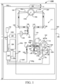
- FIG. 1 illustrates a schematic of an ATR/FTIR measurement system 100, according to an aspect of this disclosure.
- the measurement system 100 includes various optical components mounted on an assembly support 152 within an enclosure 156.
- the instrument also includes a stage or platform 186 and a moveable contact member 191.
- the contact member 191 can move rotationally and/or vertically.
- the optical components of the measurement system 100 can include an optical assembly 101.
- the optical assembly 101 can include radiation sources 102 and 144, mirrors 104, 108, 110, 148, 118, 120, 120', 126, 126', 128, and 130, beamsplitters 106 and 146, detectors and/or sensors 132 and 150, and an internally reflective element 122 (e.g. a prism).
- mirrors 104, 108, 110, 148, 118, 120, 120', 126, 126', 128, and 130 can include refractive optical elements (e.g., lenses) as well as non-planar reflective elements can also be configured with other predetermined curvatures to provide the optical paths shown in FIG. 1 .
- refractive optical elements e.g., lenses
- non-planar reflective elements can also be configured with other predetermined curvatures to provide the optical paths shown in FIG. 1 .
- such elements can be configured with concave, convex, parabolic, elliptical curvatures or any general surface needed to provide proper beam construction along any part of the beam paths as directed within system 100.
- the system 100 further includes a shaft 112, a bushing 114, and an actuator 116 coupled to mirror 110, and an electronic processor 134, an electronic display 136 (e.g., including a flat panel display element such as a liquid crystal display element, an organic light-emitting diode display element, an electrophoretic display element, or another type of display element capable of touch-screen operation), an input device 138, a storage unit 140, and a communication interface 142.
- the electronic processor 134 can be in electrical communication with a light detector 132, a storage unit 140, a communication interface 142, a display 136, an input device 138, radiation sources 102 and 144, a detector 150, a contact member 191, and an actuator 116 via communication lines 162a-j, respectively.
- the system 100 can be configured for use as an FTIR spectrometer during operation. It will be appreciated that the system 100 can be configured for other types of spectroscopy including, for example, ultraviolet, visible, Raman, or still other types of spectroscopy.
- the system 100 can provide light 168 via light source 102, which can be removable for ease of replacement, under the control of processor 134.
- the light 168 can include radiation from the light source 102, which can include a radiation source.
- the light 168 can be directed by mirror 104 to be incident on beamsplitter 106, configured as a beamsplitting optical element 106a and a phase compensating plate 106b to enable the received light 168 to be divided into two beams.
- a Michelson-type of interferometer can enable a Michelson-type of interferometer to be formed, where a first beam 170 reflects from a surface of beamsplitter 106, propagates along a beam path which is parallel to arrow 171, and is incident on fixed mirror 108. Fixed mirror 108 thereafter reflects first beam 170 in an opposite direction so as to now be directed towards beamsplitter 106.
- a second beam 172 is transmitted through beamsplitter 106 and propagates along a beam path which is parallel to double arrow 173. Second beam 172 is incident on a first surface 110a of movable mirror 110 so that upon reflection is also directed towards beamsplitter 106.
- First and second beams 170 and 172 are combined by the configuration of beamsplitter 106 and associated optics, which spatially overlaps the beams to form a modulated infrared radiation beam 174 (by way of operation of the configured Michelson interferometer) and is directed towards mirror 118. Thereafter, mirrors 118, 120, 120' direct modulated infrared radiation beam 174 to the internally reflective element 122 (depicted in FIG. 2 ). Once inside the internally reflective element 122 (often configured as a prism), beam of modulated infrared light 174 is directed to a contact surface face 122a (shown as a planar view in FIG. 1 ) of the internally reflective element 122.
- the contact surface face 122a of the internally reflective element 122 is positioned such that it contacts and supports a sample material 190 of interest, often the sample 190 has irregularities in surface construction (e.g., a powder).
- a portion of the radiation of modulated infrared light 174 is directed into the sample material 190 (See FIG. 2 ) through contact surface 122a via a desired evanescent wave effect.
- the sample 190 desirably absorbs a portion of modulated infrared light 174 that is indicative of the structure and thus the properties of the sample material 190.
- a total internal reflected portion 176 of modulated infrared light 174 includes a reduced amount of modulated radiation not absorbed by the sample 190.
- the reflected beam 176 is directed through a desired surface of the internally reflective element 122 and is thereafter directed by, for example, mirrors 126', 126, 128, and 130 in order to be interrogated by the system 100 via detection by light detector 132.
- the light detector 132 can be configured to measure one or more properties of the sample 190 based on the reflected radiation in beam 176.
- the configured mirrors 108 and 110 together with beamsplitter 106 beneficially form a Michelson interferometer.
- the plurality of measurements of the radiation in reflected beam 176 form an interferogram that includes information, such as sample absorption information.
- the processor 134 can be configured to apply one or more mathematical transformations (e.g., a Fourier transform) to the interferogram to obtain sample absorption information.
- the mirror 110 can be coupled to the shaft 112, the bushing 114, and the actuator 116.
- the shaft 112 can move freely within bushing 114 and a viscous fluid is often disposed between shaft 112 and bushing 114 to permit relative motion between the two.
- the mirror 110 can move when the actuator 116 receives control signals from the processor 134 via communication line 162i.
- the light source 144 can be configured to measure a position of the mirror 110. These components can be arranged to form a second Michelson interferometer.
- the light source 144 e.g., a monochromatic emission source (laser)
- the light source 144 can receive a control signal from processor 134 via the communication line 162g, and generates a radiation beam 178.
- light source 144 can be a configured vertical cavity surface-emitting laser (VCSEL) that generates radiation having a central wave-length of 850 nm.
- VCSEL vertical cavity surface-emitting laser
- source 144 can also include a wide variety of other sources, such as, laser diodes, light-emitting diodes, etc., capable of having radiation between 400 nm up to about 1200 nm.
- the beam 178 can be incident on beamsplitter 146, which separates radiation beam 178 into a first beam 180 and a second beam 182.
- the first beam 180 can reflect from a surface of the beamsplitter 146 and can be incident on a second surface 110b of the mirror 110.
- the second surface 110b can be positioned opposite first surface 110a of the mirror 110.
- the first beam 180 can reflect from surface 110b and can return to the beamsplitter 146.
- the second beam 182 can be transmitted through the beamsplitter 146, reflected by mirror 148, and returned to the beamsplitter 146.
- the beamsplitter 146 can combine (e.g., spatially overlaps) reflected beams 180 and 182, and the spatially overlapped beam 184 can be directed to the detector 150.
- the detector 150 can receive control signals from the processor 134 via communication line 162k, and can be configured to measure an intensity of the combined beam 184.
- the combined beam 184 can provide an interference pattern that contains desired optical position information.
- the monitoring beam 184 can enable the position (and speed and tilt, if desired), of the mirror 110 to be precisely determined by counting the peaks and valleys in the amplitude of the beam 184.
- absorption information can be compared by processor 134 to reference information (e.g., reference absorption information) stored in storage unit 140 to determine an identity of an unknown sample.
- reference information e.g., reference absorption information
- the processor 134 after a Fourier transform has been applied to the received reflected beam 176, can determine whether the absorption information for the sample matches any one or more of a plurality of sets of reference absorption information for a variety of substances that are stored as database records in the storage unit 140 or even from a database remotely located via wireless communication.
- the sample 190 is considered to be identified by processor 134.
- the processor 134 can send an electronic signal to display 136 along communication line 162d that indicates to a system operator that identification of the sample 190 was successful, and provides the name of the identified substance. If a match between the sample absorption information and the reference information is not found by processor 134, the processor 134 can send an electronic signal to display 136 that indicates to the system operator that sample 190 was not successfully identified, or that efficient optical coupling between the ATR contact surface 122a was not provided because of, for example, insufficient force applied by the contact member 191.
- the communication interface can receive and transmit signals from/to the processor 134 via communication line 162c.
- the communication interface 142 can include a wireless transmitter/receiver unit that can be configured to transmit signals from the processor 134 to other devices, and to receive signals from other devices and communicate the received signals to the processor 134.
- the communication interface 142 can permit the processor 134 to communicate with other devices via a wireless network that includes multiple devices connected to the network, and/or via a direct connection to another device.
- the processor 134 can establish a secure connection (e.g., an encrypted connection) to one or more devices to ensure that signals can only be transmitted and received by devices that are approved for use on the network.
- the light source 102 can be configured as a replaceable component.
- the light source 102 can include a broadband radiation source configured to provide infrared radiation so that the system 100 can be operated as an infrared spectrometer.
- the infrared radiation provided by source 102 can include a distribution of wavelengths, with a center wavelength of the distribution of about 10 microns.
- light source 102 can include a variety of sources known to those skilled in the art, including a heated infrared source chosen from any customized or conventional known source utilized in the field, such as, but not limited to, a wire, metal or ceramic element that can be heated to emit a continuous band of optical radiation.
- FIG. 2 illustrates a side schematic view of the stage 186 and the internally reflective element 122, according to an aspect of this disclosure.
- Axial movement between the stage 186 and the internally reflective element 122 can be substantially fixed.
- the internally reflective element 122 includes the contact surface 122a positioned to contact the sample 190.
- the sample 190 can include a powder that can be denoted by circles. It will be appreciated that the sample 190 can include a solid or a liquid.
- Light from the source 102 can enter the internally reflective element 122 through a surface 122b, and can leave the internally reflective element 122 through a surface 122c.
- An edge of the internally reflective element 122 opposite to the contact surface 122a can be supported from below by a base 204.
- a coating (not shown), such as a metal (e.g., gold), is also often applied to the internally reflective element 122 to enable stable coupling to the top of configured surface 156 of the system 100, and to also provide support to the internally reflective element 122 from above. Support provided by the surface 156 and the base 204 allows the internally reflective element 122 to withstand significant applied forces during operation without being displaced from its mounting position.
- FIG. 3 illustrates a side schematic view of a force assembly 200 and the internally reflective element 122, according to an aspect of this disclosure.
- the force assembly 200 includes an actuator 202 and a translation member 205.
- the actuator 202 can include, for example, a motor (e.g., a DC motor) or a solenoid, an electromagnetic solenoid, or other type of force actuator (e.g., a piezo-electric driven mechanism, a linear motor, a rotary motor, a pneumatic or hydraulic actuator, etc.) that can be moved in a controlled manner.
- the translation member 205 can be connected to the contact member 191 to control a movement of the contact member 191.
- the translation member 205 can include a screw mechanism, a cam, or other mechanism to control linear and/or rotational motion of the contact member 191.
- the contact member 191 can be positioned axially above the internally reflective element 122. It should be understood, however, that the contact member 191 can be positioned in any orientation with respect to the internally reflective element 122.
- the contact member 191 can be positioned below the internally reflective element 122 (e.g., where the contact member 191 drives up the internally reflective element 122).
- the contact member 191 can be positioned beside (laterally) with respect to the internally reflective element 122, which can be beneficial, e.g., in horizontally aligned systems.
- the force assembly 200 can be implemented to apply a force to internally reflective element 122, as opposed to the contact member 191.
- the contact member 191 can be statically positioned (e.g., adjacent to the sample 190), while the translation member 205 can be connected to the internally reflective element 122, which can drive the internally reflective element 122 into the sample 190.
- other force mechanisms can be implemented to exert a force onto the internally reflective element 122, which can drive the internally reflective element 122 into the sample 190.
- the sample 190 can be in direct contact with the internally reflective element 122, such that force is applied to the sample 190 via at least one of the contact member 191 and the internally reflective element 122.
- a platform such as platform 186 as depicted in FIG. 2
- an operator can control the actuator 202 to cause the contact member 191 to apply a contact force to the sample material 190 against the contact surface 122a of the internally reflective element 122.
- the contact member 191 can be controlled to raise and/or rotate into position. The movement of the contact member 191 can provide intimate contact between the contact surface 122a and the sample material 190 to enable efficient coupling of the evanescent wave and improve a signal-to-noise ratio in measurements of reflected radiation beam 176.
- the support base 204 and surface 156 can ensure that the internally reflective element 122 remains in the same position on the platform 186.
- the applied contact force by the contact member 191 onto the sample 190 can be a desired fixed force that can be a user-selectable force, or a desired force controlled through feedback from the spectrometer based on a spectrometer signature of the sample 190.
- the user can select a fixed force to apply, and the contact member 191 can be controlled to apply the fixed force to the sample 190.
- the force applied to the sample 190 by the contact member 191 can depend on feedback by, for example, the light detector 132 (see FIG. 1 ) at a detection end of an optical beam path.
- the system 100 can simultaneously and continuously query a signal strength provided by the light detector 132. If the signal strength (e.g.
- a sample spectroscopic signature strength provides a reasonable signal
- the contact member 191 stops and the force being applied to the sample 191 can be maintained. If the signal is not reasonable, the contact member 191 continues to increase a force and/or pressure applied to the sample 190 until a maximum allowable force can be applied or until an acceptable signal strength can be achieved. This operation allows the contact member 191 to stop moving as soon as there is enough contact force and/or pressure for a reasonable signal. It will be appreciated that other operations can be used to apply the force and/or pressure to the sample 190.
- the measurement system 100 further includes a sensor 206 and a controller 210.
- the controller 210 is operatively coupled to the actuator 202.
- the sensor 206 is configured to detect the force and/or a pressure applied to the sample 190 by the contact member 191 and the internally reflective element 122.
- the sensor 206 can be located, for example, on the contact member 191, on or below the internally reflective element 122, on the translation member 205, or other location where the sensor 206 can detect a force applied to the sample 190.
- the sensor 206 can include, for example, a load cell, a strain gauge, a thin-film sensor, a hydraulic force sensor, or other force sensor/transducer or pressure sensor/transducer capable of detecting a force and/or a pressure applied to the sample 190 by the contact member 191 and the internally reflective element 122. It will be appreciated that the system 100 can include more than one sensor 206 operatively coupled to the actuator 202.
- the sensor 206 can be operatively coupled to the actuator 202. It will be appreciated that the sensor could be coupled to and/or positioned at different locations on the measurement system 100. For example, the sensor 206 could be directly coupled to the contact member 191, such that a force applied to the contact member 191 by the sample 190 can be detected by the sensor 206. In an alternative aspect, the sensor 206 can be positioned at other locations on the force assembly 200 to detect the force applied to the sample 190. In another alternative aspect, the sensor 206 can be positioned on the optical assembly 101 side of the measurement system 100. For example, the sensor 206 can be positioned below the sample 190 and/or in contact with the internally reflective element 122.
- FIG. 4 illustrates a schematic of the controller 210, according to an aspect of this disclosure.
- the controller 210 is operatively coupled to the sensor 206.
- the controller 210 comprises the electronic processor 134 and the storage unit 140.
- the controller 210 can include a separate processor and/or storage unit (not shown).
- the controller 210 is configured to receive a signal from the sensor 206 indicative of the force and/or pressure applied to the sample 190 by the contact member 191 and the internally reflective element 122.
- the force and/or pressure data from the sensor 206 can be stored in the storage unit 140. Based on the force and/or pressure detected by the sensor 206 and transmitted to the controller 210, the controller sends a signal to the actuator 202 to adjust the force and/or pressure applied to the sample 190, as further described below.
- FIG. 5 illustrates a flowchart depicting a method 400 for examining the sample 190 with the ATR/FTIR measurement system 100, according to the invention.
- the sample 190 can be positioned on the contact surface 122a of the internally reflective element 122.
- the sample 190 can be placed toward a center of the internally reflective element 122 and at least partially below the contact member 191.
- the contact member 191 contacts the sample 190 by moving toward the sample 190.
- the contact member 191 applies a contact force and/or pressure to the sample 190 against the contact surface 122a.
- the contact force and/or pressure applied to the sample 190 can include a desired force and/or pressure that is user selected, controlled by signal strength feedback, or a force determined by another method.
- the sensor 206 detects an initial force and/or pressure applied to the sample 190 by the contact member 191 and the internally reflective element 122.
- the detected initial force and/or pressure can correspond to the desired contact force and/or pressure described above.
- Data indicative of the detected initial force and/or pressure can be stored in the storage unit 140 and/or a memory of the controller 210.
- the sample 190 is scanned by the optical assembly 101 to identify the sample 190.
- the measurement system 100 can be configured to cooperate with other scanning or optical systems to identify the sample 190.
- a handheld or non-handheld Raman scanning system can be used to identify the sample 190 based on Raman scattering information that can be sent to the system 100 via the communication interface 142.
- the scanning step can include directing source light from the light source 102 towards the contact surface 122a of the internally reflective element 122.
- the source light 102 optically interacts with the contact surface 122a.
- the source light 102 that optically interacts with the contact surface 122a can be detected by the light detector 132.
- the scanning step can be referred to as a forward sweep of the sample 190.
- the optical assembly 101 can perform a backward sweep to re-position the optical assembly 101 for the next scan. During the backward sweep, the optical assembly 101 is not performing a scan (e.g. non-scan period of time).
- the sample 190 can deform and/or degrade.
- the degradation can affect the contact force and/or pressure applied by the contact member 191 on the sample 190.
- the contact pressure can be reduced, thereby affecting measurements made during successive scans of the sample 190.
- the force applied to the sample 190 by the contact member 191 is adjusted prior to the optical assembly 101 performing the successive scans, as described below.
- the sensor 206 detects a resulting force and/or pressure applied to the sample 190 by the contact member 191 and the internally reflective element 122.
- a signal indicative of the resulting force is sent from the sensor 206 to the controller 210 to store in the storage unit 140 and/or a memory of the controller 210.
- the resulting force is compared to the initial force to determine whether the resulting force is different than the initial force.
- the comparing step can be performed by the processor 134 or another processor of the controller 210.
- the controller 210 sends a signal to the actuator 202 to adjust the force applied to the sample 190.
- the actuator 202 adjusts the force applied to the sample 190 from the resulting force to the initial force.
- the force adjustment step 414 can be performed during the backward sweep of the optical assembly 101.
- the force can be adjusted by the actuator 202 by adjusting a distance between the internally reflective element 122 and the contact member 191.
- the internally reflective element 122 can be axially fixed to the stage 186.
- the force can be adjusted by axially adjusting a position of the stage 186 (e.g. z-axis-controlled stage).
- the controller 210 can send a signal to an actuator (not shown) to adjust a height of the stage 186.
- the sample 190 can be re-scanned by the optical assembly 101.
- the re-scanning step 416 can include directing the source light from the light source 102 towards the contact surface 122a of the internally reflective element 122 and detecting the source light optically interacting with the contact surface 122a by the light detector 132.
- steps 412, 414, and 416 can be repeated until sufficient information regarding the optical interaction with the sample 190 can be collected and stored in the storage unit 140 and/or memory of the controller 210.
- the sample 190 can be identified.
- the measurement system 100 described and illustrated herein includes the optical assembly 101 below and supporting the sample 190. It will be appreciated that the measurement system 100 can alternatively be configured such that the optical assembly 101 can be axially above the sample 190.
- the sample 190 can be supported by the stage 186 and the axial spacing between the internally reflective element 122 and the stage 186 can be adjusted to affect the contact and the applied force on the sample 190. Either and/or both of the internally reflective element 122 and the stage 186 can be axially translatable to adjust the force on the sample 190.
Landscapes
- Physics & Mathematics (AREA)
- General Physics & Mathematics (AREA)
- Chemical & Material Sciences (AREA)
- Analytical Chemistry (AREA)
- Health & Medical Sciences (AREA)
- Life Sciences & Earth Sciences (AREA)
- Biochemistry (AREA)
- General Health & Medical Sciences (AREA)
- Immunology (AREA)
- Pathology (AREA)
- Spectroscopy & Molecular Physics (AREA)
- Investigating Or Analysing Materials By Optical Means (AREA)
Claims (13)
- Messsystem zum Untersuchen einer Probe, das Messsystem umfassend:ein innen reflektierendes Element (122), das eine Kontaktoberfläche (122a) aufweist, die konfiguriert ist, um die Probe zu tragen;ein Kontaktteil (191), das angrenzend an das innen reflektierende Element (122) positioniert ist, wobei mindestens eines von dem Kontaktteil (191) und dem innen reflektierenden Element (122) konfiguriert sind, um eine Kraft auf die Probe auszuüben, wenn die Probe auf der Kontaktoberfläche (122a) positioniert ist und das Kontaktteil (191) mit der Probe in Kontakt ist;einen Stellantrieb (202), der konfiguriert ist, um die Kraft anzupassen, die durch das Kontaktteil (191) und das innen reflektierende Element (122) auf die Probe ausgeübt wird;eine optische Anordnung (101), umfassend eine Lichtquelle (102) und einen Lichtdetektor (132), wobei die optische Anordnung (101) konfiguriert ist, um die Probe durch Lenken von Quellenlicht von der Lichtquelle (102) zu der Kontaktoberfläche (122a) und durch Erfassen von Quellenlicht durch den Lichtdetektor (132, das mit der Kontaktoberfläche (122a) optisch interagiert, abzutasten;einen Sensor (206), der konfiguriert ist, um eine Kraft zu erfassen, die durch mindestens eines von dem Kontaktteil (191) und dem innen reflektierenden Element (122) auf die Probe ausgeübt wird;wobei vor der Abtastung eine Anfangskraft, wie durch den Sensor (206) erfasst, durch das mindestens eine von dem Kontaktteil (191) und dem innen reflektierenden Element (122 auf die Probe ausgeübt wird;dadurch gekennzeichnet, dass das System derart konfiguriert ist, dass nach der Abtastung eine resultierende Kraft, die durch das mindestens eine von dem Kontaktteil (191) und dem innen reflektierenden Element (122) auf die Probe ausgeübt wird, durch den Sensor (206) erfasst wird;
unddas System ferner eine Steuervorrichtung (210) umfasst, die konfiguriert ist, um ein Signal von dem Sensor (206) zu empfangen, hinweisend auf die erfasste resultierende Kraft, wobei die Steuervorrichtung (210) ferner konfiguriert ist zum:Vergleichen der Anfangskraft mit der resultierenden Kraft;Bestimmen, dass die Anfangskraft und die resultierende Kraft unterschiedlich sind; undSteuern des Stellantriebs (202), um die Kraft, die durch das mindestens eine von dem Kontaktteil (191) und dem innen reflektierenden Element (122) auf die Probe ausgeübt wird, von der resultierenden Kraft auf die Anfangskraft anzupassen, basierend auf der Bestimmung, dass die Anfangskraft und die resultierende Kraft unterschiedlich sind;wobei das System derart konfiguriert ist, dass, nachdem die Kraft, die auf die Probe ausgeübt wird, auf die Anfangskraft angepasst wird, die Probe durch die optische Anordnung (101) erneut abgetastet wird. - Messsystem nach Anspruch 1, wobei der Sensor (206) eine Kraftmessdose umfasst.
- Messsystem nach Anspruch 1, wobei der Sensor (206) einen Dehnungsmessstreifen umfasst.
- Messsystem nach Anspruch 1, wobei der Sensor (206) mit dem Kontaktteil (191) gekoppelt ist.
- Messsystem nach Anspruch 1, wobei der Stellantrieb (202) konfiguriert ist, um einen Abstand zwischen dem innen reflektierenden Element (122) und dem Kontaktteil (191) anzupassen.
- Messsystem nach Anspruch 5, wobei der Stellantrieb (202) über eine Bühne (186) mit dem innen reflektierenden Element (122) gekoppelt ist, wobei eine axiale Bewegung zwischen der Bühne (186) und dem innen reflektierenden Element (122) im Wesentlichen fest ist, und wobei der Stellantrieb (202) konfiguriert ist, um eine Position der Bühne (186) axial anzupassen.
- Verfahren zum Untersuchen einer Probe mit einem Messsystem, das Verfahren umfassend:Positionieren einer Probe auf einer Kontaktoberfläche (122a) eines innen reflektierenden Elements (122); Inberührungbringen der Probe durch ein Kontaktteil (191), das angrenzend an das innen reflektierende Element (122) positioniert ist;Ausüben einer Kraft auf die Probe mit mindestens einem von dem Kontaktteil (191) und dem innen reflektierenden Element (122);Abtasten der Probe durch eine optische Anordnung (101), umfassend eine Lichtquelle (102) und einen Lichtdetektor (132), das Abtasten umfassend:Lenken von Quellenlicht von der Lichtquelle (102) zu der Kontaktoberfläche (122a) undErfassen von Quellenlicht, das mit der Kontaktoberfläche (122a) optisch interagiert, durch den Lichtdetektor (132),wobei vor der Abtastung eine Anfangskraft durch das mindestens eine von dem Kontaktteil (191) und dem innen reflektierenden Element (122) auf die Probe ausgeübt wird, und wobei nach der Abtastung eine resultierende Kraft durch das mindestens eine von dem Kontaktteil (191) und dem innen reflektierenden Element (122) auf die Probe ausgeübt wird, wobei sich die resultierende Kraft von der Anfangskraft unterscheidet;Erfassen, durch einen Sensor (206), der resultierenden Kraft, die durch das mindestens eine von dem Kontaktteil (191) und dem innen reflektierenden Element (122) auf die Probe ausgeübt wird;Vergleichen der Anfangskraft mit der resultierenden Kraft;Bestimmen, dass die Anfangskraft und die resultierende Kraft unterschiedlich sind;Anpassen, durch einen Stellantrieb (202), der Kraft, die durch das mindestens eine von dem Kontaktteil (191) und dem innen reflektierenden Element (122) auf die Probe ausgeübt wird, von der resultierenden Kraft auf die Anfangskraft, basierend auf der Bestimmung, dass die Anfangskraft und die resultierende Kraft unterschiedlich sind; undnachdem die Kraft, die auf die Probe ausgeübt wird, auf die Anfangskraft angepasst wird, erneutes Abtasten der Probe durch die optische Anordnung (101).
- Verfahren nach Anspruch 7, ferner umfassend:Empfangen, durch eine Steuervorrichtung (210), eines Signals von dem Sensor (206), hinweisend auf die erfasste resultierende Kraft; undSteuern, durch die Steuervorrichtung (210), des Stellantriebs (202), um die Kraft, die auf die Probe ausgeübt wird, anzupassen.
- Verfahren nach Anspruch 7, wobei der Abtastschritt ein erster Abtastschritt ist, das Verfahren
ferner umfassend:der Schritt des erneut Abtastens der Probe umfasst:Lenken von Licht zu der Kontaktoberfläche (122a) durch die Lichtquelle (102) undErfassen des Quellenlichts, das mit der Kontaktoberfläche (122a) optisch interagiert, durch den Lichtdetektor (132),wobei vor der Abtastung die Kraft auf die Anfangskraft angepasst wird. - Verfahren nach Anspruch 9, wobei nach dem ersten Abtastschritt und vor dem erneut Abtastschritt ein Nichtabtastzeitraum vorhanden ist, wobei der Anpassen-der-Kraft-Schritt während des Nichtabtastzeitraums erfolgt.
- Verfahren nach Anspruch 7, wobei der Anpassungsschritt das Anpassen eines Abstands zwischen dem innen reflektierenden Element (122) und dem Kontaktteil (191) umfasst.
- Verfahren nach Anspruch 11, wobei der Stellantrieb (202) über eine Bühne (186) mit dem innen reflektierenden Element (122) gekoppelt ist, wobei die axiale Bewegung zwischen der Bühne (186) und dem innen reflektierenden Element (122) im Wesentlichen fest ist, und wobei der Anpassungsschritt ferner ein axiales Anpassen einer Position der Bühne (186) umfasst.
- Messsystem für gedämpfte Totalreflexion zum Untersuchen einer Probe, das Messsystem umfassend:eine Bühne (186), die konfiguriert ist, um die Probe zu tragen;ein innen reflektierendes Element (122), das mit der Bühne (186) derart gekoppelt ist, dass die axiale Bewegung zwischen der Bühne (186) und dem innen reflektierenden Element (122) im Wesentlichen fest ist, wobei das innen reflektierende Element (122) eine Kontaktoberfläche (122a) aufweist, die konfiguriert ist, um die Probe zu tragen;ein Kontaktteil (191), das angrenzend an das innen reflektierende Element (122) positioniert ist,wobei mindestens eines von dem Kontaktteil (191) und dem innen reflektierenden Element (122) konfiguriert sind, um einen Druck auf die Probe auszuüben, wenn die Probe auf der Kontaktoberfläche (122a) positioniert ist und das Kontaktteil (191) mit der Probe in Kontakt ist;einen Stellantrieb (202), der konfiguriert ist, um die Höhe der Bühne (186) anzupassen, um den Druck zu beeinflussen, der durch das Kontaktteil (191) und das innen reflektierende Element (122) auf die Probe ausgeübt wird;eine optische Anordnung (101), umfassend eine Lichtquelle (102) und einen Lichtdetektor (132), wobei die optische Anordnung (101) konfiguriert ist, um die Probe durch Lenken von Licht zu der Kontaktoberfläche (122a) und durch Erfassen des Quellenlichts, das mit der Kontaktoberfläche (122a optisch interagiert, abzutasten;einen Sensor (206), der konfiguriert ist, um einen Druck zu erfassen, der durch das Kontaktteil (191) und das innen reflektierende Element (122) auf die Probe ausgeübt wird; wobei vor der Abtastung ein Anfangsdruck, wie durch den Sensor (206) erfasst, durch das Kontaktteil (191) und das innen reflektierende Element (122 auf die Probe ausgeübt wird;dadurch gekennzeichnet, dass das System für gedämpfte Totalreflexion derart konfiguriert ist, dass nach der Abtastung ein resultierender Druck, der durch das Kontaktteil (191) und das innen reflektierende Element (122) auf die Probe ausgeübt wird, durch den Sensor (206) erfasst wird;
unddas System ferner eine Steuervorrichtung (210) umfasst, die konfiguriert ist, um ein Signal von dem Sensor (206) zu empfangen, hinweisend auf den erfassten resultierenden Druck, wobei die Steuervorrichtung ferner konfiguriert ist zum:Vergleichen des Anfangsdrucks mit dem resultierenden Druck;Bestimmen, dass der Anfangsdruck und der resultierende Druck unterschiedlich sind; undSteuern des Stellantriebs (202), um die Höhe der Bühne (186) anzupassen, um den Druck, der durch das Kontaktteil (191) und das innen reflektierende Element (122) auf die Probe ausgeübt wird, von dem resultierenden Druck auf den Anfangsdruck zu ändern, basierend auf der Bestimmung, dass der Anfangsdruck und der resultierende Druck unterschiedlich sind;wobei das System derart konfiguriert ist, dass, nachdem der Druck, der auf die Probe ausgeübt wird, auf den Anfangsdruck angepasst wird, die Probe durch die optische Anordnung (101) erneut abgetastet wird.
Applications Claiming Priority (1)
| Application Number | Priority Date | Filing Date | Title |
|---|---|---|---|
| US202163222514P | 2021-07-16 | 2021-07-16 |
Publications (2)
| Publication Number | Publication Date |
|---|---|
| EP4119929A1 EP4119929A1 (de) | 2023-01-18 |
| EP4119929B1 true EP4119929B1 (de) | 2024-03-20 |
Family
ID=82595018
Family Applications (1)
| Application Number | Title | Priority Date | Filing Date |
|---|---|---|---|
| EP22184914.4A Active EP4119929B1 (de) | 2021-07-16 | 2022-07-14 | Verfahren und vorrichtung zur kraftanwendung auf eine probe unter verwendung optischer abfragetechnik |
Country Status (3)
| Country | Link |
|---|---|
| US (1) | US11971352B2 (de) |
| EP (1) | EP4119929B1 (de) |
| CN (1) | CN115615961A (de) |
Families Citing this family (1)
| Publication number | Priority date | Publication date | Assignee | Title |
|---|---|---|---|---|
| CN116832702B (zh) * | 2023-07-06 | 2025-11-21 | 郑州轻工业大学 | 一种基于金刚石对顶砧可视可控加压系统及其使用方法 |
Family Cites Families (3)
| Publication number | Priority date | Publication date | Assignee | Title |
|---|---|---|---|---|
| EP0982584B1 (de) * | 1998-08-28 | 2006-02-08 | Perkin-Elmer Limited | Spektrometrisches Zubehör zur Durchführung von Messungen abgeschwächter Totalreflexion |
| US8546761B2 (en) * | 2011-04-14 | 2013-10-01 | Thermo Electron Scientific Instruments Llc | Bellows actuated infrared (IR) stage |
| US9366626B2 (en) * | 2013-06-20 | 2016-06-14 | Thermo Scientific Portable Instruments Inc. | Method and apparatus for the application of force to a sample for detection using an electromechanical means |
-
2022
- 2022-07-14 EP EP22184914.4A patent/EP4119929B1/de active Active
- 2022-07-14 US US17/812,490 patent/US11971352B2/en active Active
- 2022-07-15 CN CN202210830803.4A patent/CN115615961A/zh active Pending
Also Published As
| Publication number | Publication date |
|---|---|
| US11971352B2 (en) | 2024-04-30 |
| US20230016736A1 (en) | 2023-01-19 |
| CN115615961A (zh) | 2023-01-17 |
| EP4119929A1 (de) | 2023-01-18 |
Similar Documents
| Publication | Publication Date | Title |
|---|---|---|
| EP4212852B1 (de) | Verfahren und vorrichtung zur anwendung von kraft auf eine probe zur detektion mit einem elektromechanischen mittel | |
| US8077324B2 (en) | Surface characteristic determining apparatus | |
| US8242448B2 (en) | Dynamic power control, beam alignment and focus for nanoscale spectroscopy | |
| US8646319B2 (en) | Dynamic power control for nanoscale spectroscopy | |
| US20110085167A1 (en) | Surface plasmon resonance spectrometer with an actuator driven angle scanning mechanism | |
| EP4119929B1 (de) | Verfahren und vorrichtung zur kraftanwendung auf eine probe unter verwendung optischer abfragetechnik | |
| US6414311B1 (en) | Spectrometer accessory for carrying out attenuated total reflectance measurements | |
| EP1817542B9 (de) | Messung des elastizizätsmoduls dielektrischer dünnfilme unter verwendung eines optischen metrologiesystems | |
| EP4119928B1 (de) | Verfahren und vorrichtung zur bestimmung einer kraft, die während einer optischen abfragetechnik auf eine probe angewandt wird | |
| CN112752969B (zh) | 用于使atr晶体和样本之间的接触自动化的方法和装置 | |
| KR100438213B1 (ko) | 박막의 물리적 특성 측정장치 및 방법 |
Legal Events
| Date | Code | Title | Description |
|---|---|---|---|
| PUAI | Public reference made under article 153(3) epc to a published international application that has entered the european phase |
Free format text: ORIGINAL CODE: 0009012 |
|
| STAA | Information on the status of an ep patent application or granted ep patent |
Free format text: STATUS: THE APPLICATION HAS BEEN PUBLISHED |
|
| AK | Designated contracting states |
Kind code of ref document: A1 Designated state(s): AL AT BE BG CH CY CZ DE DK EE ES FI FR GB GR HR HU IE IS IT LI LT LU LV MC MK MT NL NO PL PT RO RS SE SI SK SM TR |
|
| STAA | Information on the status of an ep patent application or granted ep patent |
Free format text: STATUS: REQUEST FOR EXAMINATION WAS MADE |
|
| 17P | Request for examination filed |
Effective date: 20230704 |
|
| RBV | Designated contracting states (corrected) |
Designated state(s): AL AT BE BG CH CY CZ DE DK EE ES FI FR GB GR HR HU IE IS IT LI LT LU LV MC MK MT NL NO PL PT RO RS SE SI SK SM TR |
|
| GRAP | Despatch of communication of intention to grant a patent |
Free format text: ORIGINAL CODE: EPIDOSNIGR1 |
|
| STAA | Information on the status of an ep patent application or granted ep patent |
Free format text: STATUS: GRANT OF PATENT IS INTENDED |
|
| RIC1 | Information provided on ipc code assigned before grant |
Ipc: G01N 21/65 20060101ALN20230926BHEP Ipc: G01N 21/55 20140101AFI20230926BHEP |
|
| INTG | Intention to grant announced |
Effective date: 20231030 |
|
| P01 | Opt-out of the competence of the unified patent court (upc) registered |
Effective date: 20231228 |
|
| GRAS | Grant fee paid |
Free format text: ORIGINAL CODE: EPIDOSNIGR3 |
|
| GRAA | (expected) grant |
Free format text: ORIGINAL CODE: 0009210 |
|
| STAA | Information on the status of an ep patent application or granted ep patent |
Free format text: STATUS: THE PATENT HAS BEEN GRANTED |
|
| AK | Designated contracting states |
Kind code of ref document: B1 Designated state(s): AL AT BE BG CH CY CZ DE DK EE ES FI FR GB GR HR HU IE IS IT LI LT LU LV MC MK MT NL NO PL PT RO RS SE SI SK SM TR |
|
| REG | Reference to a national code |
Ref country code: GB Ref legal event code: FG4D |
|
| REG | Reference to a national code |
Ref country code: CH Ref legal event code: EP |
|
| REG | Reference to a national code |
Ref country code: IE Ref legal event code: FG4D |
|
| REG | Reference to a national code |
Ref country code: DE Ref legal event code: R096 Ref document number: 602022002433 Country of ref document: DE |
|
| PG25 | Lapsed in a contracting state [announced via postgrant information from national office to epo] |
Ref country code: LT Free format text: LAPSE BECAUSE OF FAILURE TO SUBMIT A TRANSLATION OF THE DESCRIPTION OR TO PAY THE FEE WITHIN THE PRESCRIBED TIME-LIMIT Effective date: 20240320 |
|
| REG | Reference to a national code |
Ref country code: LT Ref legal event code: MG9D |
|
| PG25 | Lapsed in a contracting state [announced via postgrant information from national office to epo] |
Ref country code: GR Free format text: LAPSE BECAUSE OF FAILURE TO SUBMIT A TRANSLATION OF THE DESCRIPTION OR TO PAY THE FEE WITHIN THE PRESCRIBED TIME-LIMIT Effective date: 20240621 |
|
| PG25 | Lapsed in a contracting state [announced via postgrant information from national office to epo] |
Ref country code: HR Free format text: LAPSE BECAUSE OF FAILURE TO SUBMIT A TRANSLATION OF THE DESCRIPTION OR TO PAY THE FEE WITHIN THE PRESCRIBED TIME-LIMIT Effective date: 20240320 Ref country code: RS Free format text: LAPSE BECAUSE OF FAILURE TO SUBMIT A TRANSLATION OF THE DESCRIPTION OR TO PAY THE FEE WITHIN THE PRESCRIBED TIME-LIMIT Effective date: 20240620 |
|
| REG | Reference to a national code |
Ref country code: NL Ref legal event code: MP Effective date: 20240320 |
|
| PG25 | Lapsed in a contracting state [announced via postgrant information from national office to epo] |
Ref country code: RS Free format text: LAPSE BECAUSE OF FAILURE TO SUBMIT A TRANSLATION OF THE DESCRIPTION OR TO PAY THE FEE WITHIN THE PRESCRIBED TIME-LIMIT Effective date: 20240620 Ref country code: NO Free format text: LAPSE BECAUSE OF FAILURE TO SUBMIT A TRANSLATION OF THE DESCRIPTION OR TO PAY THE FEE WITHIN THE PRESCRIBED TIME-LIMIT Effective date: 20240620 Ref country code: LT Free format text: LAPSE BECAUSE OF FAILURE TO SUBMIT A TRANSLATION OF THE DESCRIPTION OR TO PAY THE FEE WITHIN THE PRESCRIBED TIME-LIMIT Effective date: 20240320 Ref country code: HR Free format text: LAPSE BECAUSE OF FAILURE TO SUBMIT A TRANSLATION OF THE DESCRIPTION OR TO PAY THE FEE WITHIN THE PRESCRIBED TIME-LIMIT Effective date: 20240320 Ref country code: GR Free format text: LAPSE BECAUSE OF FAILURE TO SUBMIT A TRANSLATION OF THE DESCRIPTION OR TO PAY THE FEE WITHIN THE PRESCRIBED TIME-LIMIT Effective date: 20240621 Ref country code: FI Free format text: LAPSE BECAUSE OF FAILURE TO SUBMIT A TRANSLATION OF THE DESCRIPTION OR TO PAY THE FEE WITHIN THE PRESCRIBED TIME-LIMIT Effective date: 20240320 Ref country code: BG Free format text: LAPSE BECAUSE OF FAILURE TO SUBMIT A TRANSLATION OF THE DESCRIPTION OR TO PAY THE FEE WITHIN THE PRESCRIBED TIME-LIMIT Effective date: 20240320 |
|
| REG | Reference to a national code |
Ref country code: AT Ref legal event code: MK05 Ref document number: 1668232 Country of ref document: AT Kind code of ref document: T Effective date: 20240320 |
|
| PG25 | Lapsed in a contracting state [announced via postgrant information from national office to epo] |
Ref country code: SE Free format text: LAPSE BECAUSE OF FAILURE TO SUBMIT A TRANSLATION OF THE DESCRIPTION OR TO PAY THE FEE WITHIN THE PRESCRIBED TIME-LIMIT Effective date: 20240320 Ref country code: LV Free format text: LAPSE BECAUSE OF FAILURE TO SUBMIT A TRANSLATION OF THE DESCRIPTION OR TO PAY THE FEE WITHIN THE PRESCRIBED TIME-LIMIT Effective date: 20240320 |
|
| PG25 | Lapsed in a contracting state [announced via postgrant information from national office to epo] |
Ref country code: NL Free format text: LAPSE BECAUSE OF FAILURE TO SUBMIT A TRANSLATION OF THE DESCRIPTION OR TO PAY THE FEE WITHIN THE PRESCRIBED TIME-LIMIT Effective date: 20240320 |
|
| PG25 | Lapsed in a contracting state [announced via postgrant information from national office to epo] |
Ref country code: NL Free format text: LAPSE BECAUSE OF FAILURE TO SUBMIT A TRANSLATION OF THE DESCRIPTION OR TO PAY THE FEE WITHIN THE PRESCRIBED TIME-LIMIT Effective date: 20240320 |
|
| PG25 | Lapsed in a contracting state [announced via postgrant information from national office to epo] |
Ref country code: IS Free format text: LAPSE BECAUSE OF FAILURE TO SUBMIT A TRANSLATION OF THE DESCRIPTION OR TO PAY THE FEE WITHIN THE PRESCRIBED TIME-LIMIT Effective date: 20240720 |
|
| PG25 | Lapsed in a contracting state [announced via postgrant information from national office to epo] |
Ref country code: PT Free format text: LAPSE BECAUSE OF FAILURE TO SUBMIT A TRANSLATION OF THE DESCRIPTION OR TO PAY THE FEE WITHIN THE PRESCRIBED TIME-LIMIT Effective date: 20240722 Ref country code: SM Free format text: LAPSE BECAUSE OF FAILURE TO SUBMIT A TRANSLATION OF THE DESCRIPTION OR TO PAY THE FEE WITHIN THE PRESCRIBED TIME-LIMIT Effective date: 20240320 |
|
| PG25 | Lapsed in a contracting state [announced via postgrant information from national office to epo] |
Ref country code: ES Free format text: LAPSE BECAUSE OF FAILURE TO SUBMIT A TRANSLATION OF THE DESCRIPTION OR TO PAY THE FEE WITHIN THE PRESCRIBED TIME-LIMIT Effective date: 20240320 |
|
| PG25 | Lapsed in a contracting state [announced via postgrant information from national office to epo] |
Ref country code: CZ Free format text: LAPSE BECAUSE OF FAILURE TO SUBMIT A TRANSLATION OF THE DESCRIPTION OR TO PAY THE FEE WITHIN THE PRESCRIBED TIME-LIMIT Effective date: 20240320 Ref country code: EE Free format text: LAPSE BECAUSE OF FAILURE TO SUBMIT A TRANSLATION OF THE DESCRIPTION OR TO PAY THE FEE WITHIN THE PRESCRIBED TIME-LIMIT Effective date: 20240320 |
|
| PG25 | Lapsed in a contracting state [announced via postgrant information from national office to epo] |
Ref country code: AT Free format text: LAPSE BECAUSE OF FAILURE TO SUBMIT A TRANSLATION OF THE DESCRIPTION OR TO PAY THE FEE WITHIN THE PRESCRIBED TIME-LIMIT Effective date: 20240320 |
|
| PG25 | Lapsed in a contracting state [announced via postgrant information from national office to epo] |
Ref country code: PL Free format text: LAPSE BECAUSE OF FAILURE TO SUBMIT A TRANSLATION OF THE DESCRIPTION OR TO PAY THE FEE WITHIN THE PRESCRIBED TIME-LIMIT Effective date: 20240320 |
|
| PG25 | Lapsed in a contracting state [announced via postgrant information from national office to epo] |
Ref country code: SK Free format text: LAPSE BECAUSE OF FAILURE TO SUBMIT A TRANSLATION OF THE DESCRIPTION OR TO PAY THE FEE WITHIN THE PRESCRIBED TIME-LIMIT Effective date: 20240320 |
|
| PG25 | Lapsed in a contracting state [announced via postgrant information from national office to epo] |
Ref country code: SM Free format text: LAPSE BECAUSE OF FAILURE TO SUBMIT A TRANSLATION OF THE DESCRIPTION OR TO PAY THE FEE WITHIN THE PRESCRIBED TIME-LIMIT Effective date: 20240320 Ref country code: SK Free format text: LAPSE BECAUSE OF FAILURE TO SUBMIT A TRANSLATION OF THE DESCRIPTION OR TO PAY THE FEE WITHIN THE PRESCRIBED TIME-LIMIT Effective date: 20240320 Ref country code: RO Free format text: LAPSE BECAUSE OF FAILURE TO SUBMIT A TRANSLATION OF THE DESCRIPTION OR TO PAY THE FEE WITHIN THE PRESCRIBED TIME-LIMIT Effective date: 20240320 Ref country code: PT Free format text: LAPSE BECAUSE OF FAILURE TO SUBMIT A TRANSLATION OF THE DESCRIPTION OR TO PAY THE FEE WITHIN THE PRESCRIBED TIME-LIMIT Effective date: 20240722 Ref country code: PL Free format text: LAPSE BECAUSE OF FAILURE TO SUBMIT A TRANSLATION OF THE DESCRIPTION OR TO PAY THE FEE WITHIN THE PRESCRIBED TIME-LIMIT Effective date: 20240320 Ref country code: IS Free format text: LAPSE BECAUSE OF FAILURE TO SUBMIT A TRANSLATION OF THE DESCRIPTION OR TO PAY THE FEE WITHIN THE PRESCRIBED TIME-LIMIT Effective date: 20240720 Ref country code: ES Free format text: LAPSE BECAUSE OF FAILURE TO SUBMIT A TRANSLATION OF THE DESCRIPTION OR TO PAY THE FEE WITHIN THE PRESCRIBED TIME-LIMIT Effective date: 20240320 Ref country code: EE Free format text: LAPSE BECAUSE OF FAILURE TO SUBMIT A TRANSLATION OF THE DESCRIPTION OR TO PAY THE FEE WITHIN THE PRESCRIBED TIME-LIMIT Effective date: 20240320 Ref country code: CZ Free format text: LAPSE BECAUSE OF FAILURE TO SUBMIT A TRANSLATION OF THE DESCRIPTION OR TO PAY THE FEE WITHIN THE PRESCRIBED TIME-LIMIT Effective date: 20240320 Ref country code: AT Free format text: LAPSE BECAUSE OF FAILURE TO SUBMIT A TRANSLATION OF THE DESCRIPTION OR TO PAY THE FEE WITHIN THE PRESCRIBED TIME-LIMIT Effective date: 20240320 |
|
| PG25 | Lapsed in a contracting state [announced via postgrant information from national office to epo] |
Ref country code: IT Free format text: LAPSE BECAUSE OF FAILURE TO SUBMIT A TRANSLATION OF THE DESCRIPTION OR TO PAY THE FEE WITHIN THE PRESCRIBED TIME-LIMIT Effective date: 20240320 |
|
| REG | Reference to a national code |
Ref country code: DE Ref legal event code: R097 Ref document number: 602022002433 Country of ref document: DE |
|
| PG25 | Lapsed in a contracting state [announced via postgrant information from national office to epo] |
Ref country code: IT Free format text: LAPSE BECAUSE OF FAILURE TO SUBMIT A TRANSLATION OF THE DESCRIPTION OR TO PAY THE FEE WITHIN THE PRESCRIBED TIME-LIMIT Effective date: 20240320 |
|
| PG25 | Lapsed in a contracting state [announced via postgrant information from national office to epo] |
Ref country code: DK Free format text: LAPSE BECAUSE OF FAILURE TO SUBMIT A TRANSLATION OF THE DESCRIPTION OR TO PAY THE FEE WITHIN THE PRESCRIBED TIME-LIMIT Effective date: 20240320 |
|
| PLBE | No opposition filed within time limit |
Free format text: ORIGINAL CODE: 0009261 |
|
| STAA | Information on the status of an ep patent application or granted ep patent |
Free format text: STATUS: NO OPPOSITION FILED WITHIN TIME LIMIT |
|
| PG25 | Lapsed in a contracting state [announced via postgrant information from national office to epo] |
Ref country code: DK Free format text: LAPSE BECAUSE OF FAILURE TO SUBMIT A TRANSLATION OF THE DESCRIPTION OR TO PAY THE FEE WITHIN THE PRESCRIBED TIME-LIMIT Effective date: 20240320 |
|
| PG25 | Lapsed in a contracting state [announced via postgrant information from national office to epo] |
Ref country code: MC Free format text: LAPSE BECAUSE OF FAILURE TO SUBMIT A TRANSLATION OF THE DESCRIPTION OR TO PAY THE FEE WITHIN THE PRESCRIBED TIME-LIMIT Effective date: 20240320 |
|
| 26N | No opposition filed |
Effective date: 20241223 |
|
| PG25 | Lapsed in a contracting state [announced via postgrant information from national office to epo] |
Ref country code: LU Free format text: LAPSE BECAUSE OF NON-PAYMENT OF DUE FEES Effective date: 20240714 |
|
| PG25 | Lapsed in a contracting state [announced via postgrant information from national office to epo] |
Ref country code: LU Free format text: LAPSE BECAUSE OF NON-PAYMENT OF DUE FEES Effective date: 20240714 |
|
| PG25 | Lapsed in a contracting state [announced via postgrant information from national office to epo] |
Ref country code: SI Free format text: LAPSE BECAUSE OF FAILURE TO SUBMIT A TRANSLATION OF THE DESCRIPTION OR TO PAY THE FEE WITHIN THE PRESCRIBED TIME-LIMIT Effective date: 20240320 Ref country code: BE Free format text: LAPSE BECAUSE OF NON-PAYMENT OF DUE FEES Effective date: 20240731 |
|
| REG | Reference to a national code |
Ref country code: BE Ref legal event code: MM Effective date: 20240731 |
|
| PG25 | Lapsed in a contracting state [announced via postgrant information from national office to epo] |
Ref country code: IE Free format text: LAPSE BECAUSE OF NON-PAYMENT OF DUE FEES Effective date: 20240714 |
|
| PGFP | Annual fee paid to national office [announced via postgrant information from national office to epo] |
Ref country code: DE Payment date: 20250616 Year of fee payment: 4 |
|
| PGFP | Annual fee paid to national office [announced via postgrant information from national office to epo] |
Ref country code: FR Payment date: 20250718 Year of fee payment: 4 |
|
| PG25 | Lapsed in a contracting state [announced via postgrant information from national office to epo] |
Ref country code: CY Free format text: LAPSE BECAUSE OF FAILURE TO SUBMIT A TRANSLATION OF THE DESCRIPTION OR TO PAY THE FEE WITHIN THE PRESCRIBED TIME-LIMIT; INVALID AB INITIO Effective date: 20220714 |