EP4119880B1 - Eddy fluid heat exchange device - Google Patents
Eddy fluid heat exchange device Download PDFInfo
- Publication number
- EP4119880B1 EP4119880B1 EP22169174.4A EP22169174A EP4119880B1 EP 4119880 B1 EP4119880 B1 EP 4119880B1 EP 22169174 A EP22169174 A EP 22169174A EP 4119880 B1 EP4119880 B1 EP 4119880B1
- Authority
- EP
- European Patent Office
- Prior art keywords
- eddy
- guiding
- fluid
- passage
- high pressure
- Prior art date
- Legal status (The legal status is an assumption and is not a legal conclusion. Google has not performed a legal analysis and makes no representation as to the accuracy of the status listed.)
- Active
Links
Images









Classifications
-
- F—MECHANICAL ENGINEERING; LIGHTING; HEATING; WEAPONS; BLASTING
- F28—HEAT EXCHANGE IN GENERAL
- F28D—HEAT-EXCHANGE APPARATUS, NOT PROVIDED FOR IN ANOTHER SUBCLASS, IN WHICH THE HEAT-EXCHANGE MEDIA DO NOT COME INTO DIRECT CONTACT
- F28D7/00—Heat-exchange apparatus having stationary tubular conduit assemblies for both heat-exchange media, the media being in contact with different sides of a conduit wall
- F28D7/16—Heat-exchange apparatus having stationary tubular conduit assemblies for both heat-exchange media, the media being in contact with different sides of a conduit wall the conduits being arranged in parallel spaced relation
- F28D7/1607—Heat-exchange apparatus having stationary tubular conduit assemblies for both heat-exchange media, the media being in contact with different sides of a conduit wall the conduits being arranged in parallel spaced relation with particular pattern of flow of the heat exchange media, e.g. change of flow direction
-
- F—MECHANICAL ENGINEERING; LIGHTING; HEATING; WEAPONS; BLASTING
- F28—HEAT EXCHANGE IN GENERAL
- F28D—HEAT-EXCHANGE APPARATUS, NOT PROVIDED FOR IN ANOTHER SUBCLASS, IN WHICH THE HEAT-EXCHANGE MEDIA DO NOT COME INTO DIRECT CONTACT
- F28D7/00—Heat-exchange apparatus having stationary tubular conduit assemblies for both heat-exchange media, the media being in contact with different sides of a conduit wall
- F28D7/10—Heat-exchange apparatus having stationary tubular conduit assemblies for both heat-exchange media, the media being in contact with different sides of a conduit wall the conduits being arranged one within the other, e.g. concentrically
- F28D7/106—Heat-exchange apparatus having stationary tubular conduit assemblies for both heat-exchange media, the media being in contact with different sides of a conduit wall the conduits being arranged one within the other, e.g. concentrically consisting of two coaxial conduits or modules of two coaxial conduits
-
- F—MECHANICAL ENGINEERING; LIGHTING; HEATING; WEAPONS; BLASTING
- F28—HEAT EXCHANGE IN GENERAL
- F28F—DETAILS OF HEAT-EXCHANGE AND HEAT-TRANSFER APPARATUS, OF GENERAL APPLICATION
- F28F1/00—Tubular elements; Assemblies of tubular elements
- F28F1/10—Tubular elements and assemblies thereof with means for increasing heat-transfer area, e.g. with fins, with projections, with recesses
- F28F1/12—Tubular elements and assemblies thereof with means for increasing heat-transfer area, e.g. with fins, with projections, with recesses the means being only outside the tubular element
-
- F—MECHANICAL ENGINEERING; LIGHTING; HEATING; WEAPONS; BLASTING
- F28—HEAT EXCHANGE IN GENERAL
- F28F—DETAILS OF HEAT-EXCHANGE AND HEAT-TRANSFER APPARATUS, OF GENERAL APPLICATION
- F28F1/00—Tubular elements; Assemblies of tubular elements
- F28F1/10—Tubular elements and assemblies thereof with means for increasing heat-transfer area, e.g. with fins, with projections, with recesses
- F28F1/12—Tubular elements and assemblies thereof with means for increasing heat-transfer area, e.g. with fins, with projections, with recesses the means being only outside the tubular element
- F28F1/34—Tubular elements and assemblies thereof with means for increasing heat-transfer area, e.g. with fins, with projections, with recesses the means being only outside the tubular element and extending obliquely
- F28F1/36—Tubular elements and assemblies thereof with means for increasing heat-transfer area, e.g. with fins, with projections, with recesses the means being only outside the tubular element and extending obliquely the means being helically wound fins or wire spirals
-
- F—MECHANICAL ENGINEERING; LIGHTING; HEATING; WEAPONS; BLASTING
- F28—HEAT EXCHANGE IN GENERAL
- F28F—DETAILS OF HEAT-EXCHANGE AND HEAT-TRANSFER APPARATUS, OF GENERAL APPLICATION
- F28F13/00—Arrangements for modifying heat-transfer, e.g. increasing, decreasing
- F28F13/02—Arrangements for modifying heat-transfer, e.g. increasing, decreasing by influencing fluid boundary
-
- F—MECHANICAL ENGINEERING; LIGHTING; HEATING; WEAPONS; BLASTING
- F28—HEAT EXCHANGE IN GENERAL
- F28F—DETAILS OF HEAT-EXCHANGE AND HEAT-TRANSFER APPARATUS, OF GENERAL APPLICATION
- F28F13/00—Arrangements for modifying heat-transfer, e.g. increasing, decreasing
- F28F13/06—Arrangements for modifying heat-transfer, e.g. increasing, decreasing by affecting the pattern of flow of the heat-exchange media
- F28F13/08—Arrangements for modifying heat-transfer, e.g. increasing, decreasing by affecting the pattern of flow of the heat-exchange media by varying the cross-section of the flow channels
-
- F—MECHANICAL ENGINEERING; LIGHTING; HEATING; WEAPONS; BLASTING
- F28—HEAT EXCHANGE IN GENERAL
- F28F—DETAILS OF HEAT-EXCHANGE AND HEAT-TRANSFER APPARATUS, OF GENERAL APPLICATION
- F28F13/00—Arrangements for modifying heat-transfer, e.g. increasing, decreasing
- F28F13/06—Arrangements for modifying heat-transfer, e.g. increasing, decreasing by affecting the pattern of flow of the heat-exchange media
- F28F13/12—Arrangements for modifying heat-transfer, e.g. increasing, decreasing by affecting the pattern of flow of the heat-exchange media by creating turbulence, e.g. by stirring, by increasing the force of circulation
Definitions
- the present invention relates to a heat exchange device, especially to a heat exchange device that exchanges heat through eddying fluid.
- a heat exchanger transfers heat between liquids to raise or lower temperatures of the liquids through flowing of the liquids.
- a heat exchanger nowadays has a casing, a heated tube and a cooled tube.
- the heated tube and the cooled tube are mounted circuitously inside the casing and are intersected and unconnected. Hot fluid flows through the heated tube of the exchanger. Cool fluid flows through the cooled tube.
- Circuitous tubes design is necessary for the heat exchanger nowadays to improve the heat transfer efficiency.
- the circuitous tubes design has a complex structure, causing high costs of production and maintenance.
- the heat exchanger nowadays needs to be improved.
- EP 3 715 763 A1 discloses an eddy fluid heat exchange device according to the preamble of claim 1.
- the present invention is to resolve the drawback that a heat exchanger nowadays has a complex structure, causing high costs of production and maintenance.
- An eddy fluid heat exchange device of the present invention is defined in claim 1 and comprises a compound tube assembly, an eddy guiding structure and at least one eddy deflecting structure.
- the compound tube assembly comprises an outer tube, an inner tube mounted in the outer tube, and an eddy passage formed between the outer tube and the inner tube.
- the eddy passage extends along an axis of the inner tube.
- the outer tube has a guiding exit formed at an end of the eddy passage.
- the eddy guiding structure is mounted at the compound tube assembly and disposed at another end, which is opposite to the guiding exit, of the eddy passage.
- the eddy guiding structure has a guiding entrance connected to the eddy passage.
- the at least one eddy deflecting structure is mounted in the eddy passage of the compound tube assembly, and is spaced apart from the eddy guiding structure, and has multiple spiral deflecting channels.
- the multiple spiral deflecting channels are annularly disposed apart from each other; two ends of each one of the spiral deflecting channels are respectively an inlet end and an outlet end; the inlet end and the outlet end are both respectively connected to the eddy passage; a bore of each one of the spiral deflecting channels gradually reduces in size from the inlet end to the outlet end.
- a high pressure fluid is fed into the guiding entrance. After passing through the eddy guiding structure, the high pressure fluid eddies and enters the eddy passage. The high pressure fluid eddies when passing through the multiple deflecting channels.
- the high pressure fluid is discharged from the guiding exit after exchanging heat with the inner tube or the outer tube.
- the present invention is connected to a high pressure fluid source by the guiding entrance, having advantages below:
- Figs. 1 , 5 , 8 and 13 are embodiments of an eddy fluid heat exchange device in accordance with the present invention.
- the eddy fluid heat exchange device comprises a compound tube assembly 10a, 10b and an eddy guiding structure 20a, 20b.
- the compound tube assembly 10a, 10b comprises an outer tube 11, an inner tube 12a, 12b mounted in the outer tube 11, and an eddy passage 13 formed between the outer tube 11 and the inner tube 12a, 12b.
- the eddy passage 13 extends along an axis of the inner tube 12a, 12b.
- the outer tube 11 has a guiding exit 14 formed at an end of the eddy passage 13.
- two opposite ends of the inner tube 12a, 12b are closed.
- an outer side of the outer tube 11 is covered by an insulation layer 15.
- the inner tube 12a, 12b has a fluid passage 121 formed inside.
- the fluid passage 121 has a fluid inlet 122 and a fluid outlet 123.
- a working fluid is fed into the fluid passage 121 from the fluid inlet 122 to exchange heat with a high pressure fluid, and is discharged from the fluid outlet 123.
- the eddy guiding structure 20a, 20b is mounted at the compound tube assembly 10a, 10b and disposed at another end, which is opposite to the guiding exit 14, of the eddy passage 13.
- the eddy guiding structure 20a, 20b has a guiding entrance 21a, 21b connected to the eddy passage 13.
- the high pressure fluid is fed into the guiding entrance 21a, 21b.
- the high pressure fluid forms eddies and enters the eddy passage 13.
- the high pressure fluid is discharged from the guiding exit 14 after exchanging heat with the inner tube 12a, 12b or the outer tube 11.
- the eddy guiding structure 20a, 20b has multiple embodiments. As shown in Figs. 1 , 4 , 8 and 10 , the eddy guiding structure 20a has multiple spiral guiding channels 22. One end of each one of the guiding channels 22 is connected to the eddy passage 13, and another end of each one of the guiding channels 22 is connected to the guiding entrance 21a. The high pressure fluid eddies when passing through the guiding channels 22. Alternatively, as shown in Figs. 7 and 15 , the guiding entrance 21b of the eddy guiding structure 20b extends along a tangent of the eddy passage 13. The high pressure fluid flows into the eddy passage 13 tangentially through the guiding entrance 21b, flowing along a wall of the outer tube 11 and forming eddies.
- the present invention comprises at least one eddy deflecting structure 30a, 30b, depending on demand.
- the at least one eddy deflecting structure 30a, 30b is mounted in the eddy passage 13 of the compound tube assembly 10a, 10b and spaced apart from the eddy guiding structure 20a, 20b.
- the at least one eddy deflecting structure 30a, 30b has multiple spiral deflecting channels 31a, 31b annularly disposed apart from each other. Two ends of each one of the multiple spiral deflecting channels 31a, 31b are respectively an inlet end 311 and an outlet end 312.
- the inlet end 311 and the outlet end 312 both are respectively connected to the eddy passage 13.
- a bore of each one of the multiple deflecting channels 31a, 31b gradually reduces in size from the inlet end 311 to the outlet end 312. The high pressure fluid eddies when passing through the multiple deflecting channels 31a, 31b.
- the present invention comprises a diversion plate 40 mounted in the eddy passage 13 of the compound tube assembly 10a, disposed adjacent to the guiding exit 14 of the outer tube 11.
- the diversion plate 40 has a spiral channel 41, connected to the eddy passage 13, formed inside.
- the spiral channel 41 guides the high pressure fluid out from the guiding exit 14.
- the guiding entrance 21a, 21b of the eddy guiding structure 20a, 20b is connected to a high pressure fluid source.
- the high pressure fluid forms eddies surrounding the inner tube 12a, 12b in the eddy passage 13. Therefore, a flowing path of the high pressure fluid in the eddy passage 13 is extended.
- complex and circuitous passages are unnecessary for the present invention, simplifying structures and lowering costs of production and maintenance.
- the extended flowing path increases a heat transfer area between the high pressure fluid and the outer tube 11 or the inner tube 12a, 12b to improve the heat transfer efficiency.
- present invention can be adjusted into multiple embodiments depending on demand.
- the multiple embodiments of the present invention are described below.
- the two opposite ends of the inner tube 12a of the compound tube assembly 10a are closed.
- the eddy guiding structure 20a has the multiple spiral guiding channels 22.
- the high pressure fluid forms eddies when passing through the multiple spiral guiding channels 22, transferring heat with fluid outside the outer tube 11 while passing the eddy passage 13.
- the two opposite ends of the inner tube 12a of the compound tube assembly 10a are closed.
- the guiding entrance 21b of the eddy guiding structure 20b extends along the tangent of the eddy passage 13.
- the high pressure fluid flows into the eddy passage 13 tangentially through the guiding entrance 21b, flowing along the wall of the outer tube 11 to eddy, transferring heat with the fluid outside the outer tube 11 while passing the eddy passage 13.
- the present invention comprises the at least one eddy deflecting structure 30a in the first and the second embodiments of the present invention.
- the outlet ends 312 of the multiple deflecting channels 31a of the at least one eddy deflecting structure 30a are disposed adjacent to an inner wall of the outer tube 11.
- the high pressure fluid flows along the multiple deflecting channels 31a adjacent to the inner wall of the outer tube 11 while passing through the at least one eddy deflecting structure 30a to improve the heat transfer efficiency between the high pressure fluid and the outer tube 11.
- the inner tube 12b of the compound tube assembly 10b has the fluid passage 121 formed inside.
- the outer side of the outer tube 11 is covered by the insulation layer 15.
- the working fluid is fed into the fluid passage 121 to exchange heat with the high pressure fluid, and then is discharged from the fluid outlet 123.
- the eddy guiding structure 20a has the multiple spiral guiding channels 22. The high pressure fluid eddies when passing through the multiple spiral guiding channels 22, transferring heat with the working fluid in the fluid passage 121 of the inner tube 12b while passing the eddy passage 13.
- the inner tube 12b of the compound tube assembly 10b has the fluid passage 121 formed inside.
- the working fluid is fed into the fluid passage 121 to exchange heat with the high pressure fluid, and then is discharged from the fluid outlet 123.
- the guiding entrance 21b of the eddy guiding structure 20b extends along the tangent of the eddy passage 13.
- the high pressure fluid flows into the eddy passage 13 tangentially through the guiding entrance 21b, flowing along the wall of the outer tube 11 and forming eddies. While passing the eddy passage 13, the high pressure fluid transfers heat with the working fluid in the fluid passage 121 of the inner tube 12b.
- the present invention comprises the at least one eddy deflecting structure 30b in the third and the fourth embodiments of the present invention.
- the outlet ends 312 of the multiple deflecting channels 31b of the eddy deflecting structure 30b are mounted near an outer wall of the inner tube 12b. While passing through the eddy deflecting structure 30b, the high pressure fluid flows along the multiple deflecting channels 31b and the outer wall of the inner tube 12b to improve the heat transfer efficiency between the high pressure fluid and the inner tube 12b.
- the eddy fluid heat exchange device is applied in a solar thermal collector 50.
- the solar thermal collector 50 comprises a base 51, a solar tracker 52 and a light reflector 53.
- the solar tracker 52 is mounted on the base 51.
- the light reflector 53 is rotatably mounted on the base 51 by a shaft, controlled by and connected to the solar tracker 52.
- the present invention is mounted on the shaft between the base 51 and the light reflector 53. Driven by the solar tracker 52 to rotate relative to the base 51, the light reflector 53 maintains facing the moving sun to reflect sun light toward the outer tube 11 of the eddy fluid heat exchange device.
- the high pressure fluid exchanges heat with the outer tube 11 while passing through the eddy passage 13.
- the high pressure fluid is discharged from the guiding exit 14 at a high temperature.
- a generator generates electricity by connecting to the present invention applied in the solar thermal collector 50.
- the multiple embodiments of the present invention may be applied in and paired with each other. As shown in Figs. 18 to 21 , multiple first embodiments pair with one third embodiment of the present invention.
- the first embodiments are parallelly mounted inside the fluid passage 121 of the third embodiment.
- the high pressure fluid inside the first embodiments and the third embodiment exchanges heat with the working fluid inside the fluid passage 121 of the third embodiment to improve the heat transfer efficiency.
- the high pressure fluid forms eddies surrounding the inner tube 12a, 12b when flowing through the eddy guiding structure 20a, 20b, thereby extending the flowing path of the high pressure fluid in the eddy passage 13.
- complex circuitous passages are unnecessary, simplifying the structures and lowering the costs of production and maintenance.
- increasing a heat transfer area between the high pressure fluid and the outer tube 11 or the inner tube 12a, 12b improves the heat transfer efficiency.
Landscapes
- Engineering & Computer Science (AREA)
- Physics & Mathematics (AREA)
- Thermal Sciences (AREA)
- Mechanical Engineering (AREA)
- General Engineering & Computer Science (AREA)
- Geometry (AREA)
- Heat-Exchange Devices With Radiators And Conduit Assemblies (AREA)
Description
- The present invention relates to a heat exchange device, especially to a heat exchange device that exchanges heat through eddying fluid.
- A heat exchanger transfers heat between liquids to raise or lower temperatures of the liquids through flowing of the liquids. A heat exchanger nowadays has a casing, a heated tube and a cooled tube. The heated tube and the cooled tube are mounted circuitously inside the casing and are intersected and unconnected. Hot fluid flows through the heated tube of the exchanger. Cool fluid flows through the cooled tube.
- In a heat exchanging process, when the hot fluid runs through the heated tube and the cool fluid runs through the cooled tube, the hot fluid and the cool fluid transfer heat through a wall of the heated tube and a wall of the cooled tube. By circuitous designs of the heated tube and the cooled tube, when the hot fluid and the cool fluid run through, a heat transfer area between the hot fluid and the cool fluid is increased, improving heat transfer efficiency.
- Circuitous tubes design is necessary for the heat exchanger nowadays to improve the heat transfer efficiency. However, the circuitous tubes design has a complex structure, causing high costs of production and maintenance. Thus, the heat exchanger nowadays needs to be improved.
-
EP 3 715 763 A1 for instance discloses an eddy fluid heat exchange device according to the preamble of claim 1. - The present invention is to resolve the drawback that a heat exchanger nowadays has a complex structure, causing high costs of production and maintenance.
- An eddy fluid heat exchange device of the present invention is defined in claim 1 and comprises a compound tube assembly, an eddy guiding structure and at least one eddy deflecting structure. The compound tube assembly comprises an outer tube, an inner tube mounted in the outer tube, and an eddy passage formed between the outer tube and the inner tube. The eddy passage extends along an axis of the inner tube. The outer tube has a guiding exit formed at an end of the eddy passage. The eddy guiding structure is mounted at the compound tube assembly and disposed at another end, which is opposite to the guiding exit, of the eddy passage. The eddy guiding structure has a guiding entrance connected to the eddy passage. The at least one eddy deflecting structure is mounted in the eddy passage of the compound tube assembly, and is spaced apart from the eddy guiding structure, and has multiple spiral deflecting channels. The multiple spiral deflecting channels are annularly disposed apart from each other; two ends of each one of the spiral deflecting channels are respectively an inlet end and an outlet end; the inlet end and the outlet end are both respectively connected to the eddy passage; a bore of each one of the spiral deflecting channels gradually reduces in size from the inlet end to the outlet end. A high pressure fluid is fed into the guiding entrance. After passing through the eddy guiding structure, the high pressure fluid eddies and enters the eddy passage. The high pressure fluid eddies when passing through the multiple deflecting channels. The high pressure fluid is discharged from the guiding exit after exchanging heat with the inner tube or the outer tube.
- The present invention is connected to a high pressure fluid source by the guiding entrance, having advantages below:
- 1. Simplified structure and lower cost: By passage designs of the compound tube assembly and the eddy guiding structure, when flowing through the eddy guiding structure, the high pressure fluid forms eddies surrounding the inner tube to extend a flowing path in the eddy passage. Thus, complex circuitous passages are unnecessary for the present invention, simplifying structures and lowing the costs of production and maintenance.
- 2. Improved heat transfer efficiency: As above mentioned, with the eddy guiding structure guiding the high pressure fluid eddies to pass through the eddy passage, the flowing path of the high pressure fluid in the eddy passage extends, increasing a heat transfer area between the high pressure fluid and the outer tube or the inner tube, and improving the heat transfer efficiency.
-
-
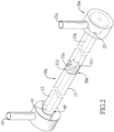
Fig. 1 is a perspective view of a first embodiment of an eddy fluid heat exchange device in accordance with the present invention; -
Fig. 2 is an another perspective view of the first embodiment of the eddy fluid heat exchange device inFig. 1 ; -
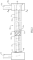
Fig. 3 is a side view of the first embodiment of the eddy fluid heat exchange device inFig. 1 ; -
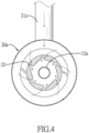
Fig. 4 is a partial sectional view across line 4-4 inFig. 3 ; -
Fig. 5 is a perspective view of a second embodiment of the eddy fluid heat exchange device in accordance with the present invention; -
Fig. 6 is a side view of the second embodiment of the eddy fluid heat exchange device inFig. 5 ; -
Fig. 7 is a partial sectional view across line 7-7 inFig. 6 ; -
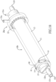
Fig. 8 is a perspective view of a third embodiment of the eddy fluid heat exchange device in accordance with the present invention; -
Fig. 9 is an another perspective view of the third embodiment of the eddy fluid heat exchange device inFig. 8 ; -
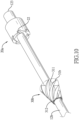
Fig. 10 is a perspective view of an eddy guiding structure, an inner tube and an eddy deflecting structure of the third embodiment of the eddy fluid heat exchange device inFig. 8 ; -
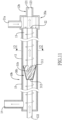
Fig. 11 is a side view of the third embodiment of the eddy fluid heat exchange device inFig. 8 ; -
Fig. 12 is a partial sectional view across line 12-12 inFig. 11 ; -
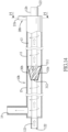
Fig. 13 is a perspective view of a fourth embodiment of the eddy fluid heat exchange device in accordance with the present invention; -
Fig. 14 is a side view of the fourth embodiment of the eddy fluid heat exchange device inFig. 13 ; -
Fig. 15 is a partial sectional view across line 15-15 inFig. 14 ; -
Fig. 16 is a perspective view of the present invention, applied in a solar thermal collector; -
Fig. 17 is a perspective view of the solar thermal collector, collecting heat; -
Fig. 18 is a perspective view of the eddy fluid heat exchange device in multiple embodiments; -
Fig. 19 is a perspective view of structures inside the eddy fluid heat exchange device inFig. 18 ; -
Fig. 20 is a side view of the eddy fluid heat exchange device inFig. 18 ; and -
Fig. 21 is a partial sectional view across line 21-21 inFig. 20 . -
Figs. 1 ,5 ,8 and13 are embodiments of an eddy fluid heat exchange device in accordance with the present invention. The eddy fluid heat exchange device comprises acompound tube assembly eddy guiding structure - With reference to
Figs. 1 ,2 ,5 ,8 ,9 , and13 , thecompound tube assembly outer tube 11, aninner tube outer tube 11, and aneddy passage 13 formed between theouter tube 11 and theinner tube eddy passage 13 extends along an axis of theinner tube outer tube 11 has a guidingexit 14 formed at an end of theeddy passage 13. In addition, with reference toFigs. 3 and6 , two opposite ends of theinner tube Figs. 11 and14 , an outer side of theouter tube 11 is covered by aninsulation layer 15. Theinner tube fluid passage 121 formed inside. Thefluid passage 121 has afluid inlet 122 and afluid outlet 123. A working fluid is fed into thefluid passage 121 from thefluid inlet 122 to exchange heat with a high pressure fluid, and is discharged from thefluid outlet 123. - With reference to
Figs. 1 ,4 ,7 ,8 ,10 , and15 , theeddy guiding structure compound tube assembly exit 14, of theeddy passage 13. Theeddy guiding structure entrance eddy passage 13. The high pressure fluid is fed into the guidingentrance eddy guiding structure eddy passage 13. The high pressure fluid is discharged from the guidingexit 14 after exchanging heat with theinner tube outer tube 11. - The
eddy guiding structure Figs. 1 ,4 ,8 and10 , theeddy guiding structure 20a has multiplespiral guiding channels 22. One end of each one of the guidingchannels 22 is connected to theeddy passage 13, and another end of each one of the guidingchannels 22 is connected to the guidingentrance 21a. The high pressure fluid eddies when passing through the guidingchannels 22. Alternatively, as shown inFigs. 7 and15 , the guidingentrance 21b of theeddy guiding structure 20b extends along a tangent of theeddy passage 13. The high pressure fluid flows into theeddy passage 13 tangentially through the guidingentrance 21b, flowing along a wall of theouter tube 11 and forming eddies. - Besides, with reference to
Figs. 2 ,3 ,6 ,10 ,11 , and14 , the present invention comprises at least oneeddy deflecting structure eddy deflecting structure eddy passage 13 of thecompound tube assembly eddy guiding structure eddy deflecting structure spiral deflecting channels spiral deflecting channels inlet end 311 and anoutlet end 312. Theinlet end 311 and theoutlet end 312 both are respectively connected to theeddy passage 13. A bore of each one of themultiple deflecting channels inlet end 311 to theoutlet end 312. The high pressure fluid eddies when passing through themultiple deflecting channels - Furthermore, with reference to
Figs. 2 and3 , the present invention comprises adiversion plate 40 mounted in theeddy passage 13 of thecompound tube assembly 10a, disposed adjacent to the guidingexit 14 of theouter tube 11. Thediversion plate 40 has aspiral channel 41, connected to theeddy passage 13, formed inside. Thespiral channel 41 guides the high pressure fluid out from the guidingexit 14. - With reference to
Figs. 2 ,3 ,6 ,10 ,11 and14 , the guidingentrance eddy guiding structure compound tube assembly eddy guiding structure eddy guiding structure inner tube eddy passage 13. Therefore, a flowing path of the high pressure fluid in theeddy passage 13 is extended. Thus, complex and circuitous passages are unnecessary for the present invention, simplifying structures and lowering costs of production and maintenance. Besides, the extended flowing path increases a heat transfer area between the high pressure fluid and theouter tube 11 or theinner tube - In addition, the present invention can be adjusted into multiple embodiments depending on demand. The multiple embodiments of the present invention are described below.
- With reference to
Figs. 1 to 4 , in a first embodiment of the present invention, the two opposite ends of theinner tube 12a of thecompound tube assembly 10a are closed. Theeddy guiding structure 20a has the multiplespiral guiding channels 22. The high pressure fluid forms eddies when passing through the multiplespiral guiding channels 22, transferring heat with fluid outside theouter tube 11 while passing theeddy passage 13. - With reference to
Figs. 5 to 7 , in a second embodiment of the present invention, the two opposite ends of theinner tube 12a of thecompound tube assembly 10a are closed. The guidingentrance 21b of theeddy guiding structure 20b extends along the tangent of theeddy passage 13. The high pressure fluid flows into theeddy passage 13 tangentially through the guidingentrance 21b, flowing along the wall of theouter tube 11 to eddy, transferring heat with the fluid outside theouter tube 11 while passing theeddy passage 13. - With reference to
Figs. 2 ,3 and6 , the present invention comprises the at least oneeddy deflecting structure 30a in the first and the second embodiments of the present invention. The outlet ends 312 of themultiple deflecting channels 31a of the at least oneeddy deflecting structure 30a are disposed adjacent to an inner wall of theouter tube 11. The high pressure fluid flows along themultiple deflecting channels 31a adjacent to the inner wall of theouter tube 11 while passing through the at least oneeddy deflecting structure 30a to improve the heat transfer efficiency between the high pressure fluid and theouter tube 11. - With reference to
Figs. 8 to 12 , in a third embodiment of the present invention, theinner tube 12b of thecompound tube assembly 10b has thefluid passage 121 formed inside. The outer side of theouter tube 11 is covered by theinsulation layer 15. The working fluid is fed into thefluid passage 121 to exchange heat with the high pressure fluid, and then is discharged from thefluid outlet 123. Theeddy guiding structure 20a has the multiplespiral guiding channels 22. The high pressure fluid eddies when passing through the multiplespiral guiding channels 22, transferring heat with the working fluid in thefluid passage 121 of theinner tube 12b while passing theeddy passage 13. - With reference to
Figs. 13 to 15 , in a fourth embodiment of the present invention, theinner tube 12b of thecompound tube assembly 10b has thefluid passage 121 formed inside. The working fluid is fed into thefluid passage 121 to exchange heat with the high pressure fluid, and then is discharged from thefluid outlet 123. The guidingentrance 21b of theeddy guiding structure 20b extends along the tangent of theeddy passage 13. The high pressure fluid flows into theeddy passage 13 tangentially through the guidingentrance 21b, flowing along the wall of theouter tube 11 and forming eddies. While passing theeddy passage 13, the high pressure fluid transfers heat with the working fluid in thefluid passage 121 of theinner tube 12b. - In addition, with reference to
Figs. 8 ,10 and15 , the present invention comprises the at least oneeddy deflecting structure 30b in the third and the fourth embodiments of the present invention. The outlet ends 312 of the multiple deflectingchannels 31b of theeddy deflecting structure 30b are mounted near an outer wall of theinner tube 12b. While passing through theeddy deflecting structure 30b, the high pressure fluid flows along the multiple deflectingchannels 31b and the outer wall of theinner tube 12b to improve the heat transfer efficiency between the high pressure fluid and theinner tube 12b. - The present invention has multiple applications. As shown in
Figs. 16 and17 , in the first embodiment of the present invention, the eddy fluid heat exchange device is applied in a solarthermal collector 50. The solarthermal collector 50 comprises abase 51, asolar tracker 52 and alight reflector 53. Thesolar tracker 52 is mounted on thebase 51. Thelight reflector 53 is rotatably mounted on thebase 51 by a shaft, controlled by and connected to thesolar tracker 52. The present invention is mounted on the shaft between the base 51 and thelight reflector 53. Driven by thesolar tracker 52 to rotate relative to thebase 51, thelight reflector 53 maintains facing the moving sun to reflect sun light toward theouter tube 11 of the eddy fluid heat exchange device. - Heated by a radiation of the sun light, the high pressure fluid exchanges heat with the
outer tube 11 while passing through theeddy passage 13. The high pressure fluid is discharged from the guidingexit 14 at a high temperature. Thus, a generator generates electricity by connecting to the present invention applied in the solarthermal collector 50. - The multiple embodiments of the present invention may be applied in and paired with each other. As shown in
Figs. 18 to 21 , multiple first embodiments pair with one third embodiment of the present invention. The first embodiments are parallelly mounted inside thefluid passage 121 of the third embodiment. The high pressure fluid inside the first embodiments and the third embodiment exchanges heat with the working fluid inside thefluid passage 121 of the third embodiment to improve the heat transfer efficiency. - By the passage designs of the
compound tube assembly eddy guiding structure inner tube eddy guiding structure eddy passage 13. Thus, complex circuitous passages are unnecessary, simplifying the structures and lowering the costs of production and maintenance. Besides, increasing a heat transfer area between the high pressure fluid and theouter tube 11 or theinner tube - Even though numerous characteristics and advantages of the present invention have been set forth in the foregoing description, together with details of the structure and features of the invention, the disclosure is illustrative only. Changes may be made in the details, especially in matters of shape, size, and arrangement of parts within the principles of the invention to the full extent indicated by the broad general meaning of the terms in which the appended claims are expressed.
Claims (7)
- An eddy fluid heat exchange comprising:a compound tube assembly (10a, 10b) comprisingan outer tube (11);an inner tube (12a, 12b) mounted in the outer tube (11);an eddy passage (13) formed between the outer tube (11) and the inner tube (12a, 12b) and extending along an axis of the inner tube (12a, 12b), the outer tube (11) havinga guiding exit (14) formed at an end of the eddy passage (13);an eddy guiding structure (20a, 20b) mounted at the compound tube assembly (10a, 10b), disposed at another end, which is opposite to the guiding exit (14), of the eddy passage (13); the eddy guiding structure (20a, 20b) havinga guiding entrance (21a, 21b) connected to the eddy passage (13); andat least one eddy deflecting structure (30a, 30b) mounted in the eddy passage (13) of the compound tube assembly (10a, 10b), spaced apart from the eddy guiding structure (20a, 20b), and havingmultiple spiral deflecting channels (31a, 31b) annularly disposed apart from each other; two ends of each one of the spiral deflecting channels (31a, 31b) respectively being an inlet end (311) and an outlet end (312); the inlet end (311) and the outlet end (312) both respectively connected to the eddy passage (13); characterised in further comprising a bore of each one of the spiral deflecting channels (31a, 31b) gradually reducing in size from the inlet end (311) to the outlet end (312); andwherein a high pressure fluid is fed into the guiding entrance (21a, 21b); after passing through the eddy guiding structure (20a, 20b), the high pressure fluid eddies and enters the eddy passage (13); the high pressure fluid eddies when passing through the multiple deflecting channels (31a, 31b)the high pressure fluid is discharged from the guiding exit (14) after exchanging heat with the inner tube (12a, 12b) or the outer tube (11).
- The eddy fluid heat exchange device as claimed in claim 1, wherein the eddy guiding structure (20a, 20b) has
multiple spiral guiding channels (22); one end of each one of the guiding channels (22) is connected to the eddy passage (13), and another end of each one of the guiding channels (22) is connected to the guiding entrance (21a, 21b); the high pressure fluid eddies when passing through the guiding channels (22). - The eddy fluid heat exchange device as claimed in claim 1, wherein the guiding entrance (21a, 21b) of the eddy guiding structure (20a, 20b) extends along a tangent of the eddy passage (13).
- The eddy fluid heat exchange device as claimed in claim 1 or 2 or 3, whereinan outer side of the outer tube (11) is covered by an insulation layer (15); andthe inner tube (12a, 12b) has
a fluid passage (121) formed inside and havinga fluid inlet (122); anda fluid outlet (123);working fluid is fed into the fluid passage (121) through the fluid inlet (122) to exchange heat with the high pressure fluid and is discharged from the fluid outlet (123). - The eddy fluid heat exchange device as claimed in claim 1 or 2 or 3, wherein the outlet end (312) of each one of the multiple deflecting channels (31a, 31b) of the eddy deflecting structure (30a, 30b) is disposed adjacent to an inner wall of the outer tube (11).
- The eddy fluid heat exchange device as claimed in claim 4, wherein the outlet end (312) of each one of the multiple deflecting channels (31a, 31b) of the eddy deflecting structure (30a, 30b) is disposed adjacent to an outer wall of the inner tube (12a, 12b).
- The eddy fluid heat exchange device as claimed in claim 5 or 6, wherein the eddy fluid heat exchange device comprises
a diversion plate (40) mounted in the eddy passage (13) of the compound tube assembly (10a, 10b), disposed adjacent to the guiding exit (14) of the outer tube (11), and having
a spiral channel (41) formed inside the diversion plate (40), connected to the eddy passage (13), and guiding the high pressure fluid out from the guiding exit (14).
Applications Claiming Priority (1)
| Application Number | Priority Date | Filing Date | Title |
|---|---|---|---|
| TW110125687A TWI763557B (en) | 2021-07-13 | 2021-07-13 | Eddy Current Heat Exchanger |
Publications (3)
| Publication Number | Publication Date |
|---|---|
| EP4119880A1 EP4119880A1 (en) | 2023-01-18 |
| EP4119880C0 EP4119880C0 (en) | 2024-05-01 |
| EP4119880B1 true EP4119880B1 (en) | 2024-05-01 |
Family
ID=81346465
Family Applications (1)
| Application Number | Title | Priority Date | Filing Date |
|---|---|---|---|
| EP22169174.4A Active EP4119880B1 (en) | 2021-07-13 | 2022-04-21 | Eddy fluid heat exchange device |
Country Status (3)
| Country | Link |
|---|---|
| US (1) | US11698227B2 (en) |
| EP (1) | EP4119880B1 (en) |
| TW (1) | TWI763557B (en) |
Families Citing this family (2)
| Publication number | Priority date | Publication date | Assignee | Title |
|---|---|---|---|---|
| CN115615217A (en) * | 2021-07-13 | 2023-01-17 | 张宏森 | Vortex Heat Exchanger |
| TWI763557B (en) | 2021-07-13 | 2022-05-01 | 張宏森 | Eddy Current Heat Exchanger |
Family Cites Families (17)
| Publication number | Priority date | Publication date | Assignee | Title |
|---|---|---|---|---|
| CA606152A (en) | 1960-10-04 | The Garrett Corporation | Axial flow vortex tube mechanism | |
| US2091119A (en) * | 1935-01-14 | 1937-08-24 | Saint-Jacques Eugene Camille | Heat exchanger |
| GB759440A (en) | 1953-10-30 | 1956-10-17 | Garrett Corp | Axial flow vortex tube mechanism |
| US5394937A (en) * | 1993-03-05 | 1995-03-07 | Nieh; Sen | Vortex heat exchange method and device |
| GB2312276B (en) | 1996-04-17 | 1998-08-19 | Stephen James Morris | Vortex flow inducer |
| RU19347U1 (en) * | 2000-01-10 | 2001-08-27 | Общество с ограниченной ответственностью "Научно-производственная фирма" | BAKING FURNACE |
| TW562854B (en) * | 2001-08-13 | 2003-11-21 | New Qu Energy Ltd | Heat transfer element with high heat transfer rate |
| WO2005057090A1 (en) | 2003-12-10 | 2005-06-23 | Matsushita Electric Industrial Co., Ltd. | Heat exchanger and cleaning device with the same |
| US7363769B2 (en) * | 2005-03-09 | 2008-04-29 | Kelix Heat Transfer Systems, Llc | Electromagnetic signal transmission/reception tower and accompanying base station employing system of coaxial-flow heat exchanging structures installed in well bores to thermally control the environment housing electronic equipment within the base station |
| KR101600296B1 (en) | 2010-08-18 | 2016-03-07 | 한온시스템 주식회사 | Double pipe heat exchanger and manufacturing method the same |
| KR20130001544A (en) | 2011-06-27 | 2013-01-04 | 이방수 | Method of manufacturing the double-wall pipe and double-wall pipe thereof |
| HK1189328A2 (en) | 2013-09-30 | 2014-05-30 | 香港现代科技有限公司 | Fluid heat exchanger and energy recovery device |
| CN107764099B (en) | 2017-10-30 | 2019-09-17 | 清华大学 | Casing enhanced heat exchange unit block and penetrate mixing rotational-flow high-efficient double pipe heat exchanger |
| CA3037942C (en) | 2019-03-25 | 2025-05-27 | Ipex Technologies Inc. | Heat exchanging device |
| CN111707113B (en) | 2020-06-10 | 2024-10-01 | 东莞理工学院 | Axial blade reverse swirl heat exchange sleeve |
| CN213748012U (en) | 2020-08-04 | 2021-07-20 | 太仓陶氏电气有限公司 | High-efficient stable form heat abstractor |
| TWI763557B (en) | 2021-07-13 | 2022-05-01 | 張宏森 | Eddy Current Heat Exchanger |
-
2021
- 2021-07-13 TW TW110125687A patent/TWI763557B/en active
- 2021-08-27 US US17/459,419 patent/US11698227B2/en active Active
-
2022
- 2022-04-21 EP EP22169174.4A patent/EP4119880B1/en active Active
Also Published As
| Publication number | Publication date |
|---|---|
| TW202303056A (en) | 2023-01-16 |
| EP4119880C0 (en) | 2024-05-01 |
| US11698227B2 (en) | 2023-07-11 |
| TWI763557B (en) | 2022-05-01 |
| US20230013985A1 (en) | 2023-01-19 |
| EP4119880A1 (en) | 2023-01-18 |
Similar Documents
| Publication | Publication Date | Title |
|---|---|---|
| AU2022309902A1 (en) | Eddy current heat exchange apparatus | |
| EP4119880A1 (en) | Eddy fluid heat exchange device | |
| EP1653185B1 (en) | Heat exchanger | |
| CA2554081C (en) | A heat exchanger, in particular of the condensation type | |
| JP7484074B2 (en) | Heat exchanger and hot water device equipped with same | |
| CN109163586A (en) | A kind of helical flow path printed circuit sheet heat exchanger | |
| EP2504632B1 (en) | Double tubing condensation exchanger for heating water and/or for producing sanitary hot water | |
| CN101206099A (en) | Vehicle Heat Exchanger | |
| US11852377B2 (en) | High efficiency tankless water heater | |
| CN117685796B (en) | Annular shell and tube heat exchanger | |
| CN213455058U (en) | Heat exchanger with rotational flow baffle plate | |
| CN112212724B (en) | Heat exchanger with swirl baffles | |
| CN223909760U (en) | Trough type solar heat collector and heat collecting pipe of heat collector | |
| CN221098991U (en) | Heat exchanger | |
| CN112985156B (en) | Fluid transposition mixing plug-in unit and fluid transposition mixing plug-in and heat sink | |
| CN104541112A (en) | Absorber arrangement for a trough collector | |
| CN223533303U (en) | Vehicle-mounted heater | |
| CN224265129U (en) | An explosion-proof heater with good thermal conductivity | |
| CN223710378U (en) | Multi-pass rapid heating electric boiler heat exchanger | |
| TWI923351B (en) | Water block | |
| CN223425800U (en) | Integral fin and efficient heat transfer element | |
| CN219810324U (en) | Heat exchange plate and gas water heating equipment | |
| GB2633412A (en) | Heat transfer fin of fin-tube type heat exchanger | |
| CN118347187A (en) | Condenser components and heat pump water heaters | |
| CN121531642A (en) | Water block |
Legal Events
| Date | Code | Title | Description |
|---|---|---|---|
| PUAI | Public reference made under article 153(3) epc to a published international application that has entered the european phase |
Free format text: ORIGINAL CODE: 0009012 |
|
| STAA | Information on the status of an ep patent application or granted ep patent |
Free format text: STATUS: THE APPLICATION HAS BEEN PUBLISHED |
|
| AK | Designated contracting states |
Kind code of ref document: A1 Designated state(s): AL AT BE BG CH CY CZ DE DK EE ES FI FR GB GR HR HU IE IS IT LI LT LU LV MC MK MT NL NO PL PT RO RS SE SI SK SM TR |
|
| STAA | Information on the status of an ep patent application or granted ep patent |
Free format text: STATUS: REQUEST FOR EXAMINATION WAS MADE |
|
| 17P | Request for examination filed |
Effective date: 20230331 |
|
| RBV | Designated contracting states (corrected) |
Designated state(s): AL AT BE BG CH CY CZ DE DK EE ES FI FR GB GR HR HU IE IS IT LI LT LU LV MC MK MT NL NO PL PT RO RS SE SI SK SM TR |
|
| GRAP | Despatch of communication of intention to grant a patent |
Free format text: ORIGINAL CODE: EPIDOSNIGR1 |
|
| STAA | Information on the status of an ep patent application or granted ep patent |
Free format text: STATUS: GRANT OF PATENT IS INTENDED |
|
| INTG | Intention to grant announced |
Effective date: 20231123 |
|
| GRAS | Grant fee paid |
Free format text: ORIGINAL CODE: EPIDOSNIGR3 |
|
| GRAA | (expected) grant |
Free format text: ORIGINAL CODE: 0009210 |
|
| STAA | Information on the status of an ep patent application or granted ep patent |
Free format text: STATUS: THE PATENT HAS BEEN GRANTED |
|
| AK | Designated contracting states |
Kind code of ref document: B1 Designated state(s): AL AT BE BG CH CY CZ DE DK EE ES FI FR GB GR HR HU IE IS IT LI LT LU LV MC MK MT NL NO PL PT RO RS SE SI SK SM TR |
|
| REG | Reference to a national code |
Ref country code: GB Ref legal event code: FG4D |
|
| REG | Reference to a national code |
Ref country code: CH Ref legal event code: EP |
|
| REG | Reference to a national code |
Ref country code: DE Ref legal event code: R096 Ref document number: 602022003153 Country of ref document: DE |
|
| REG | Reference to a national code |
Ref country code: IE Ref legal event code: FG4D |
|
| U01 | Request for unitary effect filed |
Effective date: 20240502 |
|
| U07 | Unitary effect registered |
Designated state(s): AT BE BG DE DK EE FI FR IT LT LU LV MT NL PT SE SI Effective date: 20240516 |
|
| PG25 | Lapsed in a contracting state [announced via postgrant information from national office to epo] |
Ref country code: IS Free format text: LAPSE BECAUSE OF FAILURE TO SUBMIT A TRANSLATION OF THE DESCRIPTION OR TO PAY THE FEE WITHIN THE PRESCRIBED TIME-LIMIT Effective date: 20240901 |
|
| PG25 | Lapsed in a contracting state [announced via postgrant information from national office to epo] |
Ref country code: HR Free format text: LAPSE BECAUSE OF FAILURE TO SUBMIT A TRANSLATION OF THE DESCRIPTION OR TO PAY THE FEE WITHIN THE PRESCRIBED TIME-LIMIT Effective date: 20240501 |
|
| PG25 | Lapsed in a contracting state [announced via postgrant information from national office to epo] |
Ref country code: GR Free format text: LAPSE BECAUSE OF FAILURE TO SUBMIT A TRANSLATION OF THE DESCRIPTION OR TO PAY THE FEE WITHIN THE PRESCRIBED TIME-LIMIT Effective date: 20240802 |
|
| PG25 | Lapsed in a contracting state [announced via postgrant information from national office to epo] |
Ref country code: ES Free format text: LAPSE BECAUSE OF FAILURE TO SUBMIT A TRANSLATION OF THE DESCRIPTION OR TO PAY THE FEE WITHIN THE PRESCRIBED TIME-LIMIT Effective date: 20240501 |
|
| PG25 | Lapsed in a contracting state [announced via postgrant information from national office to epo] |
Ref country code: PL Free format text: LAPSE BECAUSE OF FAILURE TO SUBMIT A TRANSLATION OF THE DESCRIPTION OR TO PAY THE FEE WITHIN THE PRESCRIBED TIME-LIMIT Effective date: 20240501 |
|
| PG25 | Lapsed in a contracting state [announced via postgrant information from national office to epo] |
Ref country code: PL Free format text: LAPSE BECAUSE OF FAILURE TO SUBMIT A TRANSLATION OF THE DESCRIPTION OR TO PAY THE FEE WITHIN THE PRESCRIBED TIME-LIMIT Effective date: 20240501 Ref country code: NO Free format text: LAPSE BECAUSE OF FAILURE TO SUBMIT A TRANSLATION OF THE DESCRIPTION OR TO PAY THE FEE WITHIN THE PRESCRIBED TIME-LIMIT Effective date: 20240801 Ref country code: IS Free format text: LAPSE BECAUSE OF FAILURE TO SUBMIT A TRANSLATION OF THE DESCRIPTION OR TO PAY THE FEE WITHIN THE PRESCRIBED TIME-LIMIT Effective date: 20240901 Ref country code: HR Free format text: LAPSE BECAUSE OF FAILURE TO SUBMIT A TRANSLATION OF THE DESCRIPTION OR TO PAY THE FEE WITHIN THE PRESCRIBED TIME-LIMIT Effective date: 20240501 Ref country code: GR Free format text: LAPSE BECAUSE OF FAILURE TO SUBMIT A TRANSLATION OF THE DESCRIPTION OR TO PAY THE FEE WITHIN THE PRESCRIBED TIME-LIMIT Effective date: 20240802 Ref country code: ES Free format text: LAPSE BECAUSE OF FAILURE TO SUBMIT A TRANSLATION OF THE DESCRIPTION OR TO PAY THE FEE WITHIN THE PRESCRIBED TIME-LIMIT Effective date: 20240501 Ref country code: RS Free format text: LAPSE BECAUSE OF FAILURE TO SUBMIT A TRANSLATION OF THE DESCRIPTION OR TO PAY THE FEE WITHIN THE PRESCRIBED TIME-LIMIT Effective date: 20240801 |
|
| PG25 | Lapsed in a contracting state [announced via postgrant information from national office to epo] |
Ref country code: CZ Free format text: LAPSE BECAUSE OF FAILURE TO SUBMIT A TRANSLATION OF THE DESCRIPTION OR TO PAY THE FEE WITHIN THE PRESCRIBED TIME-LIMIT Effective date: 20240501 |
|
| PG25 | Lapsed in a contracting state [announced via postgrant information from national office to epo] |
Ref country code: RO Free format text: LAPSE BECAUSE OF FAILURE TO SUBMIT A TRANSLATION OF THE DESCRIPTION OR TO PAY THE FEE WITHIN THE PRESCRIBED TIME-LIMIT Effective date: 20240501 Ref country code: SK Free format text: LAPSE BECAUSE OF FAILURE TO SUBMIT A TRANSLATION OF THE DESCRIPTION OR TO PAY THE FEE WITHIN THE PRESCRIBED TIME-LIMIT Effective date: 20240501 |
|
| PG25 | Lapsed in a contracting state [announced via postgrant information from national office to epo] |
Ref country code: SM Free format text: LAPSE BECAUSE OF FAILURE TO SUBMIT A TRANSLATION OF THE DESCRIPTION OR TO PAY THE FEE WITHIN THE PRESCRIBED TIME-LIMIT Effective date: 20240501 |
|
| PG25 | Lapsed in a contracting state [announced via postgrant information from national office to epo] |
Ref country code: SM Free format text: LAPSE BECAUSE OF FAILURE TO SUBMIT A TRANSLATION OF THE DESCRIPTION OR TO PAY THE FEE WITHIN THE PRESCRIBED TIME-LIMIT Effective date: 20240501 Ref country code: SK Free format text: LAPSE BECAUSE OF FAILURE TO SUBMIT A TRANSLATION OF THE DESCRIPTION OR TO PAY THE FEE WITHIN THE PRESCRIBED TIME-LIMIT Effective date: 20240501 Ref country code: RO Free format text: LAPSE BECAUSE OF FAILURE TO SUBMIT A TRANSLATION OF THE DESCRIPTION OR TO PAY THE FEE WITHIN THE PRESCRIBED TIME-LIMIT Effective date: 20240501 Ref country code: CZ Free format text: LAPSE BECAUSE OF FAILURE TO SUBMIT A TRANSLATION OF THE DESCRIPTION OR TO PAY THE FEE WITHIN THE PRESCRIBED TIME-LIMIT Effective date: 20240501 |
|
| REG | Reference to a national code |
Ref country code: DE Ref legal event code: R097 Ref document number: 602022003153 Country of ref document: DE |
|
| PLBE | No opposition filed within time limit |
Free format text: ORIGINAL CODE: 0009261 |
|
| STAA | Information on the status of an ep patent application or granted ep patent |
Free format text: STATUS: NO OPPOSITION FILED WITHIN TIME LIMIT |
|
| 26N | No opposition filed |
Effective date: 20250204 |
|
| U20 | Renewal fee for the european patent with unitary effect paid |
Year of fee payment: 4 Effective date: 20250411 |
|
| REG | Reference to a national code |
Ref country code: CH Ref legal event code: H13 Free format text: ST27 STATUS EVENT CODE: U-0-0-H10-H13 (AS PROVIDED BY THE NATIONAL OFFICE) Effective date: 20251125 |
|
| PG25 | Lapsed in a contracting state [announced via postgrant information from national office to epo] |
Ref country code: MC Free format text: LAPSE BECAUSE OF FAILURE TO SUBMIT A TRANSLATION OF THE DESCRIPTION OR TO PAY THE FEE WITHIN THE PRESCRIBED TIME-LIMIT Effective date: 20240501 |
|
| PG25 | Lapsed in a contracting state [announced via postgrant information from national office to epo] |
Ref country code: CH Free format text: LAPSE BECAUSE OF NON-PAYMENT OF DUE FEES Effective date: 20250430 |
|
| PG25 | Lapsed in a contracting state [announced via postgrant information from national office to epo] |
Ref country code: IE Free format text: LAPSE BECAUSE OF NON-PAYMENT OF DUE FEES Effective date: 20250421 |