EP4119876A1 - Domestic refrigerator with an inner container and a light source module arranged thereon, which has a specific light emission edge - Google Patents
Domestic refrigerator with an inner container and a light source module arranged thereon, which has a specific light emission edge Download PDFInfo
- Publication number
- EP4119876A1 EP4119876A1 EP22181740.6A EP22181740A EP4119876A1 EP 4119876 A1 EP4119876 A1 EP 4119876A1 EP 22181740 A EP22181740 A EP 22181740A EP 4119876 A1 EP4119876 A1 EP 4119876A1
- Authority
- EP
- European Patent Office
- Prior art keywords
- cover
- light source
- housing
- refrigeration appliance
- source module
- Prior art date
- Legal status (The legal status is an assumption and is not a legal conclusion. Google has not performed a legal analysis and makes no representation as to the accuracy of the status listed.)
- Pending
Links
Images


Classifications
-
- F—MECHANICAL ENGINEERING; LIGHTING; HEATING; WEAPONS; BLASTING
- F25—REFRIGERATION OR COOLING; COMBINED HEATING AND REFRIGERATION SYSTEMS; HEAT PUMP SYSTEMS; MANUFACTURE OR STORAGE OF ICE; LIQUEFACTION SOLIDIFICATION OF GASES
- F25D—REFRIGERATORS; COLD ROOMS; ICE-BOXES; COOLING OR FREEZING APPARATUS NOT OTHERWISE PROVIDED FOR
- F25D11/00—Self-contained movable devices, e.g. domestic refrigerators
- F25D11/02—Self-contained movable devices, e.g. domestic refrigerators with cooling compartments at different temperatures
-
- F—MECHANICAL ENGINEERING; LIGHTING; HEATING; WEAPONS; BLASTING
- F25—REFRIGERATION OR COOLING; COMBINED HEATING AND REFRIGERATION SYSTEMS; HEAT PUMP SYSTEMS; MANUFACTURE OR STORAGE OF ICE; LIQUEFACTION SOLIDIFICATION OF GASES
- F25D—REFRIGERATORS; COLD ROOMS; ICE-BOXES; COOLING OR FREEZING APPARATUS NOT OTHERWISE PROVIDED FOR
- F25D27/00—Lighting arrangements
-
- F—MECHANICAL ENGINEERING; LIGHTING; HEATING; WEAPONS; BLASTING
- F21—LIGHTING
- F21V—FUNCTIONAL FEATURES OR DETAILS OF LIGHTING DEVICES OR SYSTEMS THEREOF; STRUCTURAL COMBINATIONS OF LIGHTING DEVICES WITH OTHER ARTICLES, NOT OTHERWISE PROVIDED FOR
- F21V33/00—Structural combinations of lighting devices with other articles, not otherwise provided for
- F21V33/0004—Personal or domestic articles
- F21V33/0044—Household appliances, e.g. washing machines or vacuum cleaners
-
- F—MECHANICAL ENGINEERING; LIGHTING; HEATING; WEAPONS; BLASTING
- F21—LIGHTING
- F21V—FUNCTIONAL FEATURES OR DETAILS OF LIGHTING DEVICES OR SYSTEMS THEREOF; STRUCTURAL COMBINATIONS OF LIGHTING DEVICES WITH OTHER ARTICLES, NOT OTHERWISE PROVIDED FOR
- F21V5/00—Refractors for light sources
- F21V5/02—Refractors for light sources of prismatic shape
-
- F—MECHANICAL ENGINEERING; LIGHTING; HEATING; WEAPONS; BLASTING
- F25—REFRIGERATION OR COOLING; COMBINED HEATING AND REFRIGERATION SYSTEMS; HEAT PUMP SYSTEMS; MANUFACTURE OR STORAGE OF ICE; LIQUEFACTION SOLIDIFICATION OF GASES
- F25D—REFRIGERATORS; COLD ROOMS; ICE-BOXES; COOLING OR FREEZING APPARATUS NOT OTHERWISE PROVIDED FOR
- F25D23/00—General constructional features
- F25D23/06—Walls
- F25D23/065—Details
-
- F—MECHANICAL ENGINEERING; LIGHTING; HEATING; WEAPONS; BLASTING
- F21—LIGHTING
- F21Y—INDEXING SCHEME ASSOCIATED WITH SUBCLASSES F21K, F21L, F21S and F21V, RELATING TO THE FORM OR THE KIND OF THE LIGHT SOURCES OR OF THE COLOUR OF THE LIGHT EMITTED
- F21Y2115/00—Light-generating elements of semiconductor light sources
- F21Y2115/10—Light-emitting diodes [LED]
Definitions
- One aspect of the invention relates to a household refrigeration appliance with an inner container which uses walls to delimit at least one storage space for food in the household refrigeration appliance.
- the household refrigeration appliance also has at least one light source module, which is arranged on a wall of the inner container and which emits light into the receiving space.
- the light source module has a transparent cover through which light of a light source of the light source module is emitted from the light source module.
- Such a household refrigerator is, for example, from EP 2 594 880 B1 known.
- the cover is designed as an angled element.
- An angular part of this cover which is oriented parallel to the wall of the inner container, is non-transparent.
- a second angled portion of this angled cover is arranged at an angle to this wall of the inner container and is oriented towards the rear wall of the inner container.
- the light emission is only conditionally suitable for illuminating the recording space, especially in the front area. Furthermore, only very large-area radiation over this entire angle part cannot achieve that discrete light accents can be set. In particular, the lighting scenario in the prior art is therefore restricted and relatively weak with regard to the lighting of the recording space.
- the inner container has walls. At least one storage space for food in the household refrigeration appliance is delimited by these walls. Such a receiving space can be, for example, a freezer compartment or a refrigerator compartment.
- the household refrigeration appliance also has at least one light source module. This is arranged on a wall of the separate inner container. It is positioned in such a way that it emits light into the recording space as intended.
- the light source module has a transparent cover through which light from a light source of the light source module is emitted from the light source module into the receiving space.
- the cover is designed in particular as a plate-like bar. This cover has a front surface facing the accommodation space. In addition, the cover has a narrow, strip-shaped edge.
- this strip-shaped edge also delimits the cover.
- This strip-shaped edge is in particular arranged at an angle to the front face. In terms of area, the front surface is larger, in particular much larger, than the strip-shaped edge.
- the peripheral edge is arranged such that it is exposed towards the receiving space, at least when viewed in the width direction of the household refrigeration appliance.
- This edge is intended to be a light exit edge of the light source module, from which light from the light source can be radiated or emitted, as intended, during operation of the light source module. In particular, it is provided that light is at least partially emitted forwards out of the light source module through this light exit edge.
- the light emerging from this light exit edge is at least partially emitted towards a charging opening of the inner container.
- Such a concept makes it possible to better illuminate the receiving space, at least also in the front area or towards the loading opening. More individual and improved optical signaling effects can also be generated in this regard precisely through such a narrow light exit edge.
- a narrow band of light or a strip of light can be generated, which can also be perceived by a user when looking at the loading opening.
- Very individual light accents can therefore be generated in the recording room, in particular in the front area of the recording room.
- This light exit edge is in particular that edge which also determines the thickness of the cover.
- This light exit edge is thus the connecting surface between the front surface and a rear surface of the cover.
- the rear surface of the cover faces the light source of the light source module or an interior of a housing of the light source module.
- a front surface of the light source module is preferably five times as large, in particular at least ten times as large, as the surface of the light exit edge.
- the light exit edge is in particular a very narrow surface strip. In particular, it is formed square. Two opposite boundary edges of the surface of the light exit edge are many times larger, in particular at least 10 times, in particular at least 20 times, than the two other, shorter, opposite boundary edges. Provision can be made for the shorter boundary edges to be between 0.3 cm and 3 cm long.
- such a concept makes it possible for a narrow light band to be seen when a user looks into the recording space when the light source module is activated.
- a very individual optical illumination scenario of the receiving space towards the loading opening can thus be made possible.
- a very bright illumination is also made possible, since this narrow light exit edge also makes possible a light emission that is stronger in this respect.
- light from the light source can also be able to be emitted via the front surface in addition to the light exit edge.
- light can then be radiated over a larger area, in particular also backwards into the recording space.
- the front surface extends in a plane which is oriented at an angle greater than 0°, in particular greater than 30° and less than 120° to the plane in which the light exit edge extends.
- the plane of the light exit edge can also be compared to a vertical plane that passes through the depth direction and the height direction of the Household refrigeration appliance is stretched, be arranged inclined. In particular, in this regard, it can be arranged inclined towards the front towards the loading opening. In this context, an acute interior angle can be formed between this vertical plane and the plane of the light exit edge. As a result, the emission of light from the light exit edge towards the front towards the loading opening can be further improved.
- the edge is oriented obliquely and faces a front loading opening of the inner container, the edge forming the front end of the cover.
- the edge In its extension plane, the edge can be arranged at an angle to the wall area, which, viewed in particular in the depth direction, adjoins the edge at the front. It is also possible that the plane in which the edge extends is oriented parallel to the plane of the wall area of the wall which adjoins the edge at the front.
- the cover is a diffuser panel. It can also be referred to as a scattering plate. Light from the at least one light source of the light source module is therefore scattered accordingly by the diffuser plate. This enables a uniform light emission with a homogeneous light pattern.
- the cover it is also possible for the cover to have a light-guiding structure, through which the light from the at least one light source of the light source module can be guided in a targeted manner to the light exit edge.
- this structure is arranged in the cover, so that the light deflection defined in this regard takes place within the cover toward the light exit edge. As a result, the portion of the light that emerges from the light exit edge can be individually increased. This enables a particularly bright emission from the light exit edge.
- the cover is oriented at an angle to the vertical plane of the household refrigeration appliance.
- the vertical plane is spanned by the depth direction and the height direction of the household refrigeration appliance.
- a front end of the cover in the depth direction of the household refrigeration appliance is arranged further in than a rear end of the cover, viewed in the width direction of the household refrigeration appliance Cover. This means that the front end of the cover protrudes further into the receiving space than the rear end.
- the lighting concept mentioned above can be improved in a particularly advantageous manner by such an inclined position of the cover.
- the orientation in this regard already fundamentally supports the desired light emissions, in particular from the light exit edge at least partially towards the front.
- the preferably possible light emission to the rear via the front surface is also supported accordingly. Since the front surface is also exposed towards the recording space, a corresponding, targeted light emission into the rear area of the recording space can then also be made possible here.
- the light source module has a housing on which the cover is arranged.
- the cover can be a separate component from the housing. It is also possible in one embodiment that the cover and the housing are manufactured as one piece.
- the cover is made of plastic. However, it can also be made of real glass. In one embodiment, the cover is formed in one piece. In particular, it is designed to be transparent. This means that it is transparent to light in the spectral range visible to humans.
- the housing has an inner housing wall viewed in the width direction of the domestic refrigeration appliance.
- a front side of the inner case wall is arranged to extend further inward than a front end of the cover when viewed in the width direction.
- This inner housing wall is therefore arranged closer to the receiving space or further into the receiving space, viewed in the width direction, than an outer housing wall of the housing, viewed in the width direction. Because in this width direction this front side, which faces away from the interior of the housing of the light source module, is arranged further inside in the receiving space than the front end, a certain amount of glare protection for an observer is also achieved.
- the overhang of the front side to the light exit edge can be between 1 mm and 5 mm.
- the housing of the light source module has an outer housing wall viewed in the width direction of the household refrigeration appliance.
- this outer housing wall has a receptacle in which a rear end of the cover is arranged.
- the receptacle is a wall thinning of this outer housing wall.
- the cover has at least one snap-on element on an inside facing the housing, which snap-on element is snapped onto at least one counter-snap-on element on the separate housing of the light source module.
- a mechanical coupling between these two separate components is mechanically highly functional, easy to produce and user-friendly to handle for assembly and disassembly.
- the cover can be installed by moving it to the side.
- one exemplary embodiment provides for a spacer to be arranged at an upper end in the height direction. As a result, the cover can also be very easily removed from the housing by lifting it slightly in the upper area and sliding it upwards to the side.
- the inside of the cover which faces the housing, rests against a free edge of the inner housing wall.
- This free edge is a marginal edge of the inner housing wall. This also achieves a mechanically safe and stable positioning.
- the coverage overlaps both the free marginal edge of the inner housing wall and the free marginal edge of the outer housing wall.
- the light exit edge of the cover viewed in the depth direction of the household refrigeration appliance, is arranged directly adjacent to a front side of an inner housing wall of the housing.
- the front side is that side which faces away from the interior of the housing and which faces the receiving space.
- an arrangement is formed in series with one another between this front side of the inner housing wall and the light exit edge.
- the light exit edge is formed in this depth direction with an extent that is much smaller than the extension of the front side in this depth direction.
- the front here is at least five times, in particular at least eight times, as long as the light exit edge.
- the cover is L-shaped when viewed in cross-section.
- the cover is an elongate plate or an elongate rail. In this regard, it has a longitudinal axis along its longer extent. In this respect, the cross-section is to be seen perpendicularly to this longitudinal axis.
- a first L-leg of this L-shape covers an opening in the housing.
- a second L-leg of the L-shape is oriented protruding therefrom. It is oriented away from the housing. An exposed end of the second L-leg facing away from the first L-leg forms the edge or the light exit edge of the cover.
- the light exit edge viewed in the width direction, is offset further to the outside towards the adjacent wall of the inner container and, viewed in the depth direction, is arranged offset further to the rear of the housing of the light source module. This also enables an individual light emission concept via this light exit edge.
- the housing is an elongated, hollow rail. This is U-shaped in cross section. This cross section is also to be understood as perpendicular to a longitudinal axis of this elongated rail.
- At least one light source in particular a light-emitting diode, is arranged inside the housing.
- a light-emitting diode is arranged inside the housing.
- Corresponding electronics of the light source module can also be arranged in the housing.
- the wall of the inner container has a receiving recess on its inside facing the receiving space, in which recess the light source module is inserted.
- the light source module is thus arranged countersunk, at least in some areas, and does not undesirably protrude or extend too far into the receiving space.
- the light source module can be positioned more compactly by such an embodiment. As a result, it can also be attached in a mechanically more stable manner and is better protected against impact or the like.
- a housing wall of the housing facing the receiving space is arranged flush with a wall area of the wall adjoining the receiving recess at the front.
- the light source module is arranged sunk so far into the receiving recess, viewed in the width direction, that there is no overhang.
- the cover is colored. As a result, the light exit edge can be perceived better even when the light source module is switched off. In particular, an individual contrast to neighboring components can also be achieved by such a material coloring, so that even when the light source module is switched off, the light exit edge is optically separated from the other neighboring components. It is also possible for the cover, if it is designed as a separate component to the housing of the light source module, to be connected to the housing not only by a non-destructively detachable connection, such as at least one snap connection. Rather, a non-detachable connection can then also be provided here. For example, gluing or welding can be provided here.
- the housing prefferably be designed with the cover as a one-piece component, for example as a 2K plastic component. It is also possible that the
- Light exit edge is formed only over a partial length of the entire light source module. In particular, it is formed over the entire length of the light source module.
- the outside of the inner container can be covered with a thermally insulating material, in particular rigid polyurethane foam.
- the inner container can be made of plastic, in particular polystyrene, and can be produced by deep-drawing or injection molding.
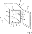
- a household refrigeration appliance 1 In 1 an embodiment of a household refrigeration appliance 1 is shown in a perspective view.
- the household refrigeration appliance 1 is intended to be designed for storing and preserving food.
- the household refrigeration appliance 1 can be a refrigerator or a freezer or a fridge-freezer combination appliance.
- the household refrigeration appliance 1 can be a free-standing household refrigeration appliance or a built-in appliance.
- the household refrigeration appliance 1 has an outer housing 2 .
- the household refrigeration appliance 1 has an inner container 3 . This is separate from the outer housing 2 .
- the inner container 3 is accommodated in the outer case 2 .
- Thermally insulating material 5 is placed in an intermediate space 4 between the outer housing 2 and the inner container 3 .
- the inner container 3 has walls 6, 7, 8, 9 and 10 on. These walls 6 to 10 delimit at least one accommodation space 11 of the household refrigeration appliance 1.
- the accommodation space 11 is intended to accommodate food. It can be a refrigerator compartment or a freezer compartment.
- the household refrigeration appliance 1 also has a door 12 . This is movably arranged on the body, which includes the outer housing 2 and the inner container 3 . As a result, a front loading opening 13 of the inner container 3 can be closed.
- the household refrigeration appliance 1 also has at least one light source module 14 . This is arranged on an inner side 9a of the wall 9 of the inner container 3 facing the receiving space 13 . This position is only to be understood as an example. In addition to or instead of this, a light source module can also be arranged, for example, on an inside of the wall 7 and/or on an inside of the wall 8 and/or on an inside of the wall 6 .
- the wall 9 is provided with a receiving recess 15 on the inside 9a.
- This blind hole-like trough is provided to accommodate the light source module 14 .
- the light source module 14 is therefore arranged countersunk in the wall 9 at least in certain areas.
- In 2 is an enlarged view of portion I in 1 shown. It can be seen that the light source module 14 is designed here as an elongate rail. It is oriented here with a longitudinal axis A in the vertical direction (y-direction) of the household refrigeration appliance 1 .
- the receiving recess 15 is formed to the side in the width direction (x-direction) of the household refrigeration appliance 1 , so that in this respect the light source module 14 is sunk into this receiving recess 15 when viewed in the width direction.
- the light source module 14 has a housing 16 .
- an inner housing wall 17 can be seen in this regard. In the exemplary embodiment, this is exposed towards the receiving space 11 .
- this inner housing wall 17 has a front side 17a. This is the visible side facing the receiving space 11 .
- the inner housing wall 17 is designed here as a plate-like strip.
- the housing 16, as shown in the perspective sectional view in 3 can be seen, an outer housing wall 18 on.
- the outer housing wall 18 is arranged further away from the receiving space 11 than the inner housing wall 17 in this width direction.
- the housing 16 has a connecting wall 19 . This is provided for connecting the inner housing wall 17 and the outer housing wall 18 .
- the housing 16 is U-shaped when viewed perpendicularly to the longitudinal axis A in cross section.
- At least one light source 21 is arranged in the interior 20 of the housing 16 .
- the light source 21 can include a light emitting diode.
- the electronics of the light source module 14 are also arranged in the interior 20 .
- the light source module 16 has a cover 22 .
- the cover 22 is transparent at least in certain areas.
- the cover 22 is designed here as an elongate plate strip.
- This related plate has a front face 23 .
- the front surface 23 faces away from the interior 20 .
- the front surface 23 faces the receiving space 11 .
- the front face 23 is exposed to the receiving space 13 .
- the front surface 23 is a large-surface front side with respect to the strip-shaped plate.
- this cover 22 also has a rear surface 24 .
- the cover 22 also has a marginal edge 25 as provided in a plate-like configuration of a component.
- This marginal edge 25 is a narrow side of the cover 22.
- the marginal edge 25 is designed here as a light exit edge 26, as intended and in accordance with its function. This means that defined and desired light from the light source 21 emerges from this edge 25, which forms the light exit edge 26, as intended.
- this light exit edge 26 is a narrow strip area. This strip surface is smaller, in particular much smaller, than the large surface of the front surface 23 and/or the large surface of the rear surface 24. The surface of the light exit edge 26 extends towards the receiving space 11. It is exposed to the receiving space 11, in particular completely exposed.
- the plane in which the light exit edge 26 extends over a surface area can also be arranged inclined to a plane that is spanned by the height direction and the depth direction of the household refrigeration appliance 1 .
- this plane of the light exit edge 26 can be arranged at an acute angle to the vertical plane and in connection with the loading opening 13 can be oriented toward this acute angle. Due to these light exit edges 26, light is also emitted, as intended, at least in part forwards into the front region of the receiving space 11, in particular also towards the loading opening 13. This light exit edge 26 is arranged so that it is completely exposed towards the receiving space 11 .
- the light exit edge 26 is a vertical surface strip here.
- the cover 22 also has a further opposite marginal edge 27 . This faces the wall 9 . It is not designed and arranged for light emission. In the exemplary embodiment it is provided that the edge 25 and thus the light exit edge 26 is oriented obliquely. Viewed in the depth direction, the edge 25 forms the front end 28 of the cover 22.
- the cover 22 is designed in particular as a diffuser plate or light-scattering plate.
- the cover 22 is oriented with its plate-like element at an angle to the vertical plane.
- the front end 28 of the cover 22 in the depth direction of the household refrigeration appliance 1 is offset further inwards towards the receiving space 11, viewed in the width direction of the household refrigeration appliance 1, than a rear end 29 of the cover 22, viewed in the depth direction.
- the rear end 29 is in particular outer edge 27 formed.
- the front side 17a of the inner housing wall 17 is offset further into the receiving space 11 than the front end 28 of the cover 22.
- the light exit edge 26 is arranged in the width direction at the same width as the front side 17a. In particular, this is provided in each case when the planes of the front side 17a and those of the light exit edge 26 extend in a common plane or in planes parallel to one another.
- the plane in which the light exit edge 26 extends can also be arranged at an angle to the vertical plane. As a result, this plane is also oriented at an angle to the front side 17a. In particular, this light exit edge 26 is then oriented inclined towards the loading opening 13 .
- the outer housing wall 18 has a receptacle 30 .
- the rear or outer end 29 of the cover 22 extends into this receptacle 30.
- this receptacle 30 is formed by an end region of the outer housing wall 18 that is reduced in thickness. As can be seen, the outer edge 27 is completely covered by this receptacle 30 .
- cover 22 protrudes beyond a free end 31 of the inner housing wall 17 viewed in the width direction and thus covers this free end 31 at least in regions.
- the cover 22 has at least one snap-on element 32 . This is snapped into place with at least one counter-snapping element which is arranged on the housing 16 .
- a plurality of snap elements and counter-snap elements are preferably provided.
- the inside or rear surface 24 of the cover 22 rests against the free end or the free edge 31 of the inner housing wall 17 .
- the edge 25 and thus the light exit edge 26 are arranged directly on the front side 17a of the inner housing wall 17 .
- In 4 is the component arrangement in 3 shown in the cutting plane.
- In 4 is in this regard a sectional plane or a horizontal sectional plane shown that is different 3 is.
- the housing 16 has a coupling part 33 .
- This protrudes through a recess 34 in the wall 9, in particular in the receiving recess 15.
- This coupling part 33 thus protrudes into the intermediate space 4.
- a separate backing part or a mounting part 35 is arranged. This allows the light source module 14 to be attached to this mounting part 35 .
- FIG 5 a further exemplary embodiment of a household refrigeration appliance 1 is shown in a perspective sectional view.
- a detail is shown here, in which the wall 7 of the inner container 3 is shown.
- the cover 22 is not completely planar with the faceplate, but the faceplate is angled in relation thereto.
- the front surface 23 is uneven here, in particular angled.
- the surface of the light exit edge 26 extends over a surface area in a vertical plane that is spanned by the depth direction and the height direction.
- an arrangement that is flush with the front side 17a is realized, so that in particular the plane of the front side 17a is the same as the plane of the light exit edge 26 .
- FIG. 7 is in a perspective view accordingly figure 5 and 6 another embodiment of a household refrigeration appliance 1 is shown.
- a different configuration of the cover 22 is again provided. Viewed in the depth direction, the light exit edge 26 is not arranged immediately adjacent to the front side 17a of the inner housing wall 17 . Rather, here the cover 22 is L-shaped when viewed in cross section.
- a first L-leg 37 is arranged so that it rests against the housing 16, respectively an opening of the housing 16 closes or covers. In the exemplary embodiment, this L-leg 37 has no thin light exit edge that would be exposed.
- This cover 22 has a second leg 38 of the L. This is angled and protrudes from the first leg 37 of the L, in particular protrudes away from the housing 16 . An exposed end 39 of this second leg 38 of the L has the edge 25 and thus the light exit edge 26 . This is inclined.
- cover 22 as shown in figure 5 and 6 is shown, with the cover according to FIG 7 is realized.
- a cover 22 then also has a light exit edge 26 or 36 which is exposed to the side or to the front and which, viewed in the depth direction, is formed immediately to the rear adjoining the front side 17a.
- a flush arrangement is preferably provided between the front side 17a and the wall area of the wall 7 or the wall 9 adjoining forward in the depth direction.
- These wall areas 40 ( 3 ) and 41 are shown accordingly.
Landscapes
- Engineering & Computer Science (AREA)
- General Engineering & Computer Science (AREA)
- Chemical & Material Sciences (AREA)
- Combustion & Propulsion (AREA)
- Physics & Mathematics (AREA)
- Mechanical Engineering (AREA)
- Thermal Sciences (AREA)
- Devices That Are Associated With Refrigeration Equipment (AREA)
Abstract
Ein Haushaltskältegerät (1) mit einem Innenbehälter (3), der mit Wänden (6, 7, 8, 9, 10) zumindest einen Aufnahmeraum (11) für Lebensmittel des Haushaltskältegeräts (1) begrenzt, und mit einem Lichtquellenmodul (14), das an einer Wand (6, 7, 8, 9, 10) des Innenbehälters (3) angeordnet ist und Licht in den Aufnahmeraum (11) emittiert, wobei das Lichtquellenmodul (14) eine transparente Abdeckung (22) aufweist, durch welche Licht einer Lichtquelle (21) des Lichtquellenmoduls (14) aus dem Lichtquellenmodul (14) emittiert wird, wobei die Abdeckung (22) eine plattenartige Leiste ist, die eine Frontfläche (23) und eine schmale, streifenförmige Randkante (25) aufweist, wobei die Randkante (25) zumindest in Breitenrichtung (x) des Haushaltskältegeräts (1) zum Aufnahmeraum (11) hin frei liegend angeordnet ist und die Randkante (25) eine Lichtaustrittskante (26, 36) ist, aus welcher Licht der Lichtquelle (21) im Betrieb des Lichtquellenmoduls (14) nach vorne aus dem Lichtquellenmodul (14) emittiert ist.

Description
Ein Aspekt der Erfindung betrifft ein Haushaltskältegerät mit einem Innenbehälter, der mit Wänden zumindest einen Aufnahmeraum für Lebensmittel des Haushaltskältegeräts begrenzt. Das Haushaltskältegerät weist darüber hinaus zumindest ein Lichtquellenmodul auf, das an einer Wand des Innenbehälters angeordnet ist und welches Licht in den Aufnahmeraum emittiert. Das Lichtquellenmodul weist eine transparente Abdeckung auf, durch welche Licht einer Lichtquelle des Lichtquellenmoduls aus dem Lichtquellenmodul emittiert wird.One aspect of the invention relates to a household refrigeration appliance with an inner container which uses walls to delimit at least one storage space for food in the household refrigeration appliance. The household refrigeration appliance also has at least one light source module, which is arranged on a wall of the inner container and which emits light into the receiving space. The light source module has a transparent cover through which light of a light source of the light source module is emitted from the light source module.
Ein derartiges Haushaltskältegerät ist beispielsweise aus der
Bei einem solchen Konzept ist die Lichtabstrahlung nur bedingt tauglich, den Aufnahmeraum insbesondere auch im vorderen Bereich zu beleuchten. Des Weiteren kann durch eine nur sehr großflächige Abstrahlung über dieses gesamte Winkelteil nicht erreicht werden, dass diskrete Lichtakzente gesetzt werden können. Insbesondere ist daher das Beleuchtungsszenario im Stand der Technik eingeschränkt und bezüglich der Beleuchtung des Aufnahmeraums relativ schwach.With such a concept, the light emission is only conditionally suitable for illuminating the recording space, especially in the front area. Furthermore, only very large-area radiation over this entire angle part cannot achieve that discrete light accents can be set. In particular, the lighting scenario in the prior art is therefore restricted and relatively weak with regard to the lighting of the recording space.
Es ist Aufgabe der vorliegenden Erfindung, ein Haushaltskältegerät zu schaffen, bei welchem die Abstrahlung von Licht eines Lichtquellenmoduls, welches an einer Wand eines Innenbehälters angeordnet ist, verbessert ist.It is the object of the present invention to create a household refrigeration appliance in which the emission of light from a light source module which is arranged on a wall of an inner container is improved.
Diese Aufgabe wird durch ein Haushaltskältegerät, welches die Merkmale nach Anspruch 1 aufweist, gelöst.This object is achieved by a household refrigeration appliance which has the features according to
Ein Aspekt der Erfindung betrifft ein Haushaltskältegerät mit einem Innenbehälter. Der Innenbehälter weist Wände auf. Durch diese Wände ist zumindest ein Aufnahmeraum für Lebensmittel des Haushaltskältegeräts begrenzt. Ein derartiger Aufnahmeraum kann beispielsweise ein Gefrierfach oder ein Kühlfach sein. Das Haushaltskältegerät weist darüber hinaus zumindest ein Lichtquellenmodul auf. Dieses ist an einer Wand des dazu separaten Innenbehälters angeordnet. Es ist so positioniert, dass es bestimmungsgemäß Licht in den Aufnahmeraum emittiert. Das Lichtquellenmodul weist eine transparente Abdeckung auf, durch welche Licht einer Lichtquelle des Lichtquellenmoduls aus dem Lichtquellenmodul in den Aufnahmeraum emittiert wird. Die Abdeckung ist insbesondere als plattenartige Leiste ausgebildet. Diese Abdeckung weist eine Frontfläche auf, die dem Aufnahmeraum zugewandt ist. Darüber hinaus weist die Abdeckung eine schmale, streifenförmige Randkante auf. Diese streifenförmige Randkante begrenzt insbesondere auch die Abdeckung. Diese streifenförmige Randkante ist insbesondere in einem Winkel zur Frontfläche angeordnet. Flächenmäßig ist die Frontfläche größer, insbesondere viel größer, als die streifenförmige Randkante. Die Randkante ist zumindest in Breitenrichtung des Haushaltskältegeräts betrachtet zum Aufnahmeraum hin freiliegend angeordnet. Diese Randkante ist bestimmungsgemäß eine Lichtaustrittskante des Lichtquellenmoduls, aus welcher bestimmungsgemäß Licht der Lichtquelle im Betrieb des Lichtquellenmoduls abstrahlbar beziehungsweise emittierbar ist. Insbesondere ist es vorgesehen, dass durch diese Lichtaustrittskante Licht zumindest anteilig nach vorne aus dem Lichtquellenmodul emittiert ist. Dies bedeutet, dass in Tiefenrichtung des Haushaltskältegeräts betrachtet das aus dieser Lichtaustrittskante austretende Licht zumindest anteilig zu einer Beschickungsöffnung des Innenbehälters hin emittiert ist. Durch ein derartiges Konzept ist es ermöglicht, den Aufnahmeraum zumindest auch im vorderen Bereich oder zur Beschickungsöffnung hin verbessert beleuchten zu können. Gerade durch eine derartige schmale Lichtaustrittskante können diesbezüglich auch individuellere und verbesserte optische Signalisierungseffekte generiert werden. Ein diesbezüglich schmales Lichtband beziehungsweise ein Lichtstreifen kann erzeugt werden, welches durch einen Nutzer bei Betrachtung der Beschickungsöffnung auch wahrgenommen werden kann. Sehr individuelle Lichtakzente sind daher im Aufnahmeraum, insbesondere im vorderen Bereich des Aufnahmeraums, erzeugbar.One aspect of the invention relates to a household refrigeration appliance with an inner container. The inner container has walls. At least one storage space for food in the household refrigeration appliance is delimited by these walls. Such a receiving space can be, for example, a freezer compartment or a refrigerator compartment. The household refrigeration appliance also has at least one light source module. This is arranged on a wall of the separate inner container. It is positioned in such a way that it emits light into the recording space as intended. The light source module has a transparent cover through which light from a light source of the light source module is emitted from the light source module into the receiving space. The cover is designed in particular as a plate-like bar. This cover has a front surface facing the accommodation space. In addition, the cover has a narrow, strip-shaped edge. In particular, this strip-shaped edge also delimits the cover. This strip-shaped edge is in particular arranged at an angle to the front face. In terms of area, the front surface is larger, in particular much larger, than the strip-shaped edge. The peripheral edge is arranged such that it is exposed towards the receiving space, at least when viewed in the width direction of the household refrigeration appliance. This edge is intended to be a light exit edge of the light source module, from which light from the light source can be radiated or emitted, as intended, during operation of the light source module. In particular, it is provided that light is at least partially emitted forwards out of the light source module through this light exit edge. This means that viewed in the depth direction of the household refrigeration appliance, the light emerging from this light exit edge is at least partially emitted towards a charging opening of the inner container. Such a concept makes it possible to better illuminate the receiving space, at least also in the front area or towards the loading opening. More individual and improved optical signaling effects can also be generated in this regard precisely through such a narrow light exit edge. In this respect, a narrow band of light or a strip of light can be generated, which can also be perceived by a user when looking at the loading opening. Very individual light accents can therefore be generated in the recording room, in particular in the front area of the recording room.
Diese Lichtaustrittskante ist insbesondere diejenige Randkante, die auch die Dicke der Abdeckung bestimmt. Diese Lichtaustrittskante ist somit die Verbindungsfläche zwischen der Frontfläche und einer Rückfläche der Abdeckung. Die Rückfläche der Abdeckung ist in dem Zusammenhang der Lichtquelle des Lichtquellenmoduls zugewandt beziehungsweise einem Inneren eines Gehäuses des Lichtquellenmoduls zugewandt. Eine Frontfläche des Lichtquellenmoduls ist vorzugsweise fünfmal so groß, insbesondere zumindest zehnmal so groß, als die Fläche der Lichtaustrittskante. Die Lichtaustrittskante ist insbesondere ein sehr schmaler Flächenstreifen. Er ist insbesondere viereckig gebildet. Zwei gegenüberliegende Begrenzungsränder der Fläche der Lichtaustrittskante sind um ein Vielfaches, insbesondere zumindest das 10-fache, insbesondere zumindest das 20-fache, größer, als die beiden anderen, dazu kürzeren, gegenüberliegenden Begrenzungsränder. Es kann vorgesehen sein, dass die kürzeren Begrenzungsränder zwischen 0,3cm und 3cm lang sind.This light exit edge is in particular that edge which also determines the thickness of the cover. This light exit edge is thus the connecting surface between the front surface and a rear surface of the cover. In this context, the rear surface of the cover faces the light source of the light source module or an interior of a housing of the light source module. A front surface of the light source module is preferably five times as large, in particular at least ten times as large, as the surface of the light exit edge. The light exit edge is in particular a very narrow surface strip. In particular, it is formed square. Two opposite boundary edges of the surface of the light exit edge are many times larger, in particular at least 10 times, in particular at least 20 times, than the two other, shorter, opposite boundary edges. Provision can be made for the shorter boundary edges to be between 0.3 cm and 3 cm long.
Darüber hinaus kann durch ein derartiges Konzept ermöglicht werden, dass bei Betrachtung eines Nutzers in den Aufnahmeraum hinein ein diesbezüglich schmales Lichtband zu erkennen ist, wenn das Lichtquellenmodul aktiviert ist. Es kann somit ein sehr individuelles optisches Ausleuchtungsszenario des Aufnahmeraums zur Beschickungsöffnung hin ermöglicht werden. Insbesondere ist diesbezüglich in einem Ausführungsbeispiel auch eine sehr lichtstarke Beleuchtung ermöglicht, da über diese schmale Lichtaustrittskante auch eine diesbezüglich stärkere Lichtemission ermöglicht ist.In addition, such a concept makes it possible for a narrow light band to be seen when a user looks into the recording space when the light source module is activated. A very individual optical illumination scenario of the receiving space towards the loading opening can thus be made possible. In this regard, in particular, in one exemplary embodiment, a very bright illumination is also made possible, since this narrow light exit edge also makes possible a light emission that is stronger in this respect.
Darüber hinaus ist es in einem Ausführungsbeispiel auch ermöglicht, dass zusätzlich zu der Lichtaustrittskante Licht der Lichtquelle auch über die Frontfläche abstrahlbar ist. Diesbezüglich kann dann Licht insbesondere auch nach hinten in den Aufnahmeraum großflächiger abgestrahlt werden. Die Frontfläche erstreckt sich in einer Ebene, die in einem Winkel größer 0°, insbesondere größer 30° und kleiner 120° zur Ebene orientiert ist, in der sich die Lichtaustrittskante erstreckt.Furthermore, in one exemplary embodiment, it is also possible for light from the light source to also be able to be emitted via the front surface in addition to the light exit edge. In this regard, light can then be radiated over a larger area, in particular also backwards into the recording space. The front surface extends in a plane which is oriented at an angle greater than 0°, in particular greater than 30° and less than 120° to the plane in which the light exit edge extends.
Es kann vorgesehen sein, dass die Ebene, in der sich die Lichtaustrittskante flächig erstreckt, durch die Tiefenrichtung und die Höhenrichtung des Haushaltskältegeräts aufgespannt ist. Die Ebene der Lichtaustrittskante kann auch gegenüber einer Vertikalebene, die durch die Tiefenrichtung und die Höhenrichtung des Haushaltskältegeräts aufgespannt ist, geneigt angeordnet sein. Insbesondere kann sie diesbezüglich nach vorne zur Beschickungsöffnung hin geneigt angeordnet sein. Es kann in dem Zusammenhang ein spitzer Innenwinkel zwischen dieser Vertikalebene und der Ebene der Lichtaustrittskante ausgebildet sein. Dadurch kann die Lichtabstrahlung aus der Lichtaustrittskante nach vorne hin zur Beschickungsöffnung nochmals verbessert werden.Provision can be made for the plane in which the light exit edge extends over a surface area to be spanned by the depth direction and the height direction of the household refrigeration appliance. The plane of the light exit edge can also be compared to a vertical plane that passes through the depth direction and the height direction of the Household refrigeration appliance is stretched, be arranged inclined. In particular, in this regard, it can be arranged inclined towards the front towards the loading opening. In this context, an acute interior angle can be formed between this vertical plane and the plane of the light exit edge. As a result, the emission of light from the light exit edge towards the front towards the loading opening can be further improved.
In einem Ausführungsbeispiel ist die Randkante schräg orientiert und einer frontseitigen Beschickungsöffnung des Innenbehälters zugewandt, wobei die Randkante das vordere Ende der Abdeckung bildet. Die Randkante kann in ihrer Erstreckungsebene in einem Winkel zum Wandbereich angeordnet sein, der insbesondere in Tiefenrichtung betrachtet nach vorne hin an die Randkante anschließt. Möglich ist es auch, dass die Ebene, in der sich die Randkante erstreckt, parallel zur Ebene des Wandbereichs der Wand orientiert ist, die nach vorne hin an die Randkante anschließt.In one embodiment, the edge is oriented obliquely and faces a front loading opening of the inner container, the edge forming the front end of the cover. In its extension plane, the edge can be arranged at an angle to the wall area, which, viewed in particular in the depth direction, adjoins the edge at the front. It is also possible that the plane in which the edge extends is oriented parallel to the plane of the wall area of the wall which adjoins the edge at the front.
In einem Ausführungsbeispiel ist die Abdeckung eine Diffusorplatte. Sie kann auch als Streuplatte bezeichnet werden. Licht der zumindest einen Lichtquelle des Lichtquellenmoduls wird daher durch die Diffusorplatte entsprechend gestreut. Eine gleichmäßige Lichtabstrahlung mit einem homogenen Lichtbild ist dadurch ermöglicht.In one embodiment, the cover is a diffuser panel. It can also be referred to as a scattering plate. Light from the at least one light source of the light source module is therefore scattered accordingly by the diffuser plate. This enables a uniform light emission with a homogeneous light pattern.
In einem Ausführungsbeispiel ist es auch möglich, dass die Abdeckung eine Lichtleitstruktur aufweist, durch welche das Licht der zumindest einen Lichtquelle des Lichtquellenmoduls gezielt zu der Lichtaustrittskante leitbar ist. Insbesondere ist dazu vorgesehen, dass diese Struktur in der Abdeckung angeordnet ist, sodass die diesbezüglich definierte Lichtlenkung innerhalb der Abdeckung zu der Lichtaustrittskante hin erfolgt. Dadurch kann der Anteil des Lichts, der aus der Lichtaustrittskante austritt, individuell erhöht werden. Eine besonders lichtstarke Abstrahlung aus der Lichtaustrittskante ist dadurch ermöglicht.In one exemplary embodiment, it is also possible for the cover to have a light-guiding structure, through which the light from the at least one light source of the light source module can be guided in a targeted manner to the light exit edge. In particular, it is provided that this structure is arranged in the cover, so that the light deflection defined in this regard takes place within the cover toward the light exit edge. As a result, the portion of the light that emerges from the light exit edge can be individually increased. This enables a particularly bright emission from the light exit edge.
In einem Ausführungsbeispiel ist die Abdeckung in einem Winkel zur Vertikalebene des Haushaltskältegeräts orientiert. Die Vertikalebene ist durch die Tiefenrichtung und die Höhenrichtung des Haushaltskältegeräts aufgespannt. Insbesondere ist ein in Tiefenrichtung des Haushaltskältegeräts vorderes Ende der Abdeckung in Breitenrichtung des Haushaltskältegeräts betrachtet weiter innen angeordnet, als ein hinteres Ende der Abdeckung. Dies bedeutet, dass das vordere Ende der Abdeckung weiter in den Aufnahmeraum hineinragt, als das hintere Ende. Durch eine derartige Schrägstellung der Abdeckung kann das oben genannte Beleuchtungskonzept in besonders vorteilhafter Weise verbessert werden. Die diesbezügliche Orientierung unterstützt bereits grundsätzlich die gewünschten Lichtabstrahlungen, insbesondere aus der Lichtaustrittskante zumindest anteilig nach vorne hin. Darüber hinaus wird auch die vorzugsweise mögliche Lichtabstrahlung über die Frontfläche nach hinten hin entsprechend unterstützt. Da die Frontfläche zum Aufnahmeraum hin ebenfalls freiliegt, kann hier dann auch eine entsprechende gezielte Lichtabstrahlung in den hinteren Bereich des Aufnahmeraums ermöglicht werden.In one embodiment, the cover is oriented at an angle to the vertical plane of the household refrigeration appliance. The vertical plane is spanned by the depth direction and the height direction of the household refrigeration appliance. In particular, a front end of the cover in the depth direction of the household refrigeration appliance is arranged further in than a rear end of the cover, viewed in the width direction of the household refrigeration appliance Cover. This means that the front end of the cover protrudes further into the receiving space than the rear end. The lighting concept mentioned above can be improved in a particularly advantageous manner by such an inclined position of the cover. The orientation in this regard already fundamentally supports the desired light emissions, in particular from the light exit edge at least partially towards the front. In addition, the preferably possible light emission to the rear via the front surface is also supported accordingly. Since the front surface is also exposed towards the recording space, a corresponding, targeted light emission into the rear area of the recording space can then also be made possible here.
In einem Ausführungsbeispiel weist das Lichtquellenmodul ein Gehäuse auf, an dem die Abdeckung angeordnet ist. Die Abdeckung kann eine zum Gehäuse separate Komponente sein. Möglich ist es in einem Ausführungsbeispiel auch, dass die Abdeckung und das Gehäuse als ein Stück hergestellt sind.In one embodiment, the light source module has a housing on which the cover is arranged. The cover can be a separate component from the housing. It is also possible in one embodiment that the cover and the housing are manufactured as one piece.
Die Abdeckung ist in einem Ausführungsbeispiel aus Kunststoff ausgebildet. Sie kann jedoch auch aus Echtglas ausgebildet sein. Die Abdeckung ist in einem Ausführungsbeispiel einstückig ausgebildet. Sie ist insbesondere transparent ausgebildet. Dies bedeutet, dass sie für Licht im für den Menschen sichtbaren Spektralbereich durchlässig ist.In one exemplary embodiment, the cover is made of plastic. However, it can also be made of real glass. In one embodiment, the cover is formed in one piece. In particular, it is designed to be transparent. This means that it is transparent to light in the spectral range visible to humans.
In einem Ausführungsbeispiel weist das Gehäuse eine in Breitenrichtung des Haushaltskältegeräts betrachtet innere Gehäusewand auf. Eine Frontseite der inneren Gehäusewand ist in Breitenrichtung betrachtet weiter sich nach innen erstreckend angeordnet, als ein vorderes Ende der Abdeckung. Diese innere Gehäusewand ist somit in Breitenrichtung betrachtet näher zum Aufnahmeraum hin beziehungsweise weiter in den Aufnahmeraum hinein angeordnet, als eine in Breitenrichtung betrachtet äußere Gehäusewand des Gehäuses. In dem in dieser Breitenrichtung diese Frontseite, die dem Inneren des Gehäuses des Lichtquellenmoduls abgewandt ist, weiter innenliegend in dem Aufnahmeraum angeordnet ist, als das vordere Ende, wird auch ein gewisser Blendschutz für einen Beobachter erreicht. Durch den diesbezüglich in Breitenrichtung erzeugten Überstand der Frontseite gegenüber dem vorderen Ende der Abdeckung, das durch die Lichtaustrittskante gebildet wird, ist andererseits auch ein gewisser Stoßschutz erreicht, sodass die Lichtaustrittskante diesbezüglich auch geschützt ist. In Breitenrichtung betrachtet kann der Überstand der Frontseite zur Lichtaustrittskante zwischen 1 mm und 5 mm betragen.In one exemplary embodiment, the housing has an inner housing wall viewed in the width direction of the domestic refrigeration appliance. A front side of the inner case wall is arranged to extend further inward than a front end of the cover when viewed in the width direction. This inner housing wall is therefore arranged closer to the receiving space or further into the receiving space, viewed in the width direction, than an outer housing wall of the housing, viewed in the width direction. Because in this width direction this front side, which faces away from the interior of the housing of the light source module, is arranged further inside in the receiving space than the front end, a certain amount of glare protection for an observer is also achieved. On the other hand, a certain degree of impact protection is also achieved due to the projection of the front side in the width direction in relation to the front end of the cover, which is formed by the light exit edge. so that the light exit edge is also protected in this regard. Viewed in the width direction, the overhang of the front side to the light exit edge can be between 1 mm and 5 mm.
In einem Ausführungsbeispiel weist das Gehäuse des Lichtquellenmoduls eine in Breitenrichtung des Haushaltskältegeräts betrachtet äußere Gehäusewand auf. Diese äußere Gehäusewand weist in einem Ausführungsbeispiel eine Aufnahme auf, in welcher ein hinteres Ende der Abdeckung angeordnet ist. Die Aufnahme ist in einem Ausführungsbeispiel eine Wandverdünnung dieser äußeren Gehäusewand. Dadurch überlappt das hintere Ende der Abdeckung im diesbezüglich angeordneten Zustand an dem Gehäuse mit dieser äußeren Gehäusewand. Eine entsprechend vorteilhafte Positionierung und ein mechanisch fester Sitz der Abdeckung an dem Gehäuse an diesem hinteren Ende der Abdeckung sind dadurch ermöglicht. Darüber hinaus liegt durch diese Ausgestaltung das hintere Ende der Abdeckung nicht frei, sondern ist durch die äußere Gehäusewand abgedeckt. Insbesondere ist hier eine vollständige Abdeckung ausgebildet.In one exemplary embodiment, the housing of the light source module has an outer housing wall viewed in the width direction of the household refrigeration appliance. In one exemplary embodiment, this outer housing wall has a receptacle in which a rear end of the cover is arranged. In one exemplary embodiment, the receptacle is a wall thinning of this outer housing wall. As a result, the rear end of the cover overlaps this outer housing wall in the state in which it is arranged on the housing. A correspondingly advantageous positioning and a mechanically secure fit of the cover on the housing at this rear end of the cover are thereby made possible. In addition, due to this configuration, the rear end of the cover is not exposed but is covered by the outer housing wall. In particular, complete coverage is formed here.
In einem Ausführungsbeispiel weist die Abdeckung an einer dem Gehäuse zugewandten Innenseite zumindest ein Schnappelement auf, welches mit zumindest einem Gegenschnappelement an dem dazu separaten Gehäuse des Lichtquellenmoduls verschnappt ist. Eine derartige mechanische Kopplung zwischen diesen beiden separaten Komponenten ist mechanisch hochfunktionell, einfach erzeugbar und für die Montage und Demontage nutzerfreundlich handhabbar. In dem Zusammenhang kann in einem Ausführungsbeispiel die Montage der Abdeckung über ein seitliches Verschieben erfolgen. Um eine Demontage auch im eingebauten Zustand des Lichtquellenmoduls zu ermöglichen, ist es in einem Ausführungsbeispiel vorgesehen, dass an einem in Höhenrichtung oberen Ende ein Platzhalter angeordnet ist. Dadurch kann die Abdeckung auch durch ein leichtes Anheben im oberen Bereich sowie ein seitliches Verschieben nach oben sehr einfach von dem Gehäuse demontiert werden.In one exemplary embodiment, the cover has at least one snap-on element on an inside facing the housing, which snap-on element is snapped onto at least one counter-snap-on element on the separate housing of the light source module. Such a mechanical coupling between these two separate components is mechanically highly functional, easy to produce and user-friendly to handle for assembly and disassembly. In this context, in one exemplary embodiment, the cover can be installed by moving it to the side. In order to enable disassembly even when the light source module is installed, one exemplary embodiment provides for a spacer to be arranged at an upper end in the height direction. As a result, the cover can also be very easily removed from the housing by lifting it slightly in the upper area and sliding it upwards to the side.
In einem Ausführungsbeispiel liegt die Abdeckung mit einer dem Gehäuse zugewandten Innenseite an einem freien Rand der inneren Gehäusewand an. Dieser freie Rand ist eine Randkante der inneren Gehäusewand. Auch dadurch wird eine mechanisch sichere und stabile Positionierung erreicht. In einem Ausführungsbeispiel überlappt die Abdeckung sowohl die freie Randkante der inneren Gehäusewand als auch die freie Randkante der äußeren Gehäusewand.In one exemplary embodiment, the inside of the cover, which faces the housing, rests against a free edge of the inner housing wall. This free edge is a marginal edge of the inner housing wall. This also achieves a mechanically safe and stable positioning. In one embodiment, the coverage overlaps both the free marginal edge of the inner housing wall and the free marginal edge of the outer housing wall.
In einem Ausführungsbeispiel ist die Lichtaustrittskante der Abdeckung in Tiefenrichtung des Haushaltskältegeräts betrachtet direkt an eine Frontseite einer inneren Gehäusewand des Gehäuses anschließend angeordnet. Die Frontseite ist diesbezüglich diejenige Seite, die dem Inneren des Gehäuses abgewandt ist und die dem Aufnahmeraum zugewandt ist. Dadurch wird in Tiefenrichtung des Haushaltskältegeräts betrachtet eine Anordnung in Reihe zueinander zwischen dieser Frontseite der inneren Gehäusewand und der Lichtaustrittskante gebildet. Die Lichtaustrittskante ist in dieser Tiefenrichtung mit einem Ausmaß ausgebildet, welches viel kleiner ist als die Erstreckung der Frontseite in dieser Tiefenrichtung. Insbesondere ist hier die Frontseite zumindest fünfmal, insbesondere zumindest achtmal, so lang, wie die Lichtaustrittskante.In one exemplary embodiment, the light exit edge of the cover, viewed in the depth direction of the household refrigeration appliance, is arranged directly adjacent to a front side of an inner housing wall of the housing. In this regard, the front side is that side which faces away from the interior of the housing and which faces the receiving space. As a result, viewed in the depth direction of the household refrigeration appliance, an arrangement is formed in series with one another between this front side of the inner housing wall and the light exit edge. The light exit edge is formed in this depth direction with an extent that is much smaller than the extension of the front side in this depth direction. In particular, the front here is at least five times, in particular at least eight times, as long as the light exit edge.
In einem Ausführungsbeispiel ist die Abdeckung im Querschnitt betrachtet L-förmig. Die Abdeckung ist, wie dies bereits oben dargelegt wurde, in einem Ausführungsbeispiel eine längliche Platte beziehungsweise eine längliche Schiene. Diesbezüglich weist sie entlang ihres längeren Ausmaßes eine Längsachse auf. Der Querschnitt ist diesbezüglich senkrecht zu dieser Längsachse zu sehen. Ein erster L-Schenkel dieser L-Form deckt eine Öffnung des Gehäuses ab. Ein zweiter L-Schenkel der L-Form ist davon abstehend orientiert. Er ist dem Gehäuse abgewandt orientiert. Ein dem ersten L-Schenkel abgewandtes freiliegendes Ende des zweiten L-Schenkels bildet die Randkante beziehungsweise die Lichtaustrittskante der Abdeckung. Durch dieses Ausführungsbeispiel ist die Lichtaustrittskante in Breitenrichtung betrachtet weiter zur benachbarten Wand des Innenbehälters hin nach außen versetzt und in Tiefenrichtung betrachtet weiter von dem Gehäuse des Lichtquellenmoduls nach hinten versetzt angeordnet. Auch dadurch ist dann ein individuelles Lichtabstrahlkonzept über diese Lichtaustrittskante ermöglicht.In one embodiment, the cover is L-shaped when viewed in cross-section. As has already been explained above, in one exemplary embodiment the cover is an elongate plate or an elongate rail. In this regard, it has a longitudinal axis along its longer extent. In this respect, the cross-section is to be seen perpendicularly to this longitudinal axis. A first L-leg of this L-shape covers an opening in the housing. A second L-leg of the L-shape is oriented protruding therefrom. It is oriented away from the housing. An exposed end of the second L-leg facing away from the first L-leg forms the edge or the light exit edge of the cover. As a result of this exemplary embodiment, the light exit edge, viewed in the width direction, is offset further to the outside towards the adjacent wall of the inner container and, viewed in the depth direction, is arranged offset further to the rear of the housing of the light source module. This also enables an individual light emission concept via this light exit edge.
In einem Ausführungsbeispiel ist das Gehäuse eine längliche, hohle Schiene. Diese ist im Querschnitt U-förmig. Auch dieser Querschnitt ist senkrecht zu einer Längsachse dieser länglichen Schiene zu verstehen.In one embodiment, the housing is an elongated, hollow rail. This is U-shaped in cross section. This cross section is also to be understood as perpendicular to a longitudinal axis of this elongated rail.
Im Inneren des Gehäuses ist zumindest eine Lichtquelle, insbesondere eine Leuchtdiode, angeordnet. Es können auch mehrere Leuchtdioden diesbezüglich angeordnet sein. Auch entsprechende Elektronik des Lichtquellenmoduls kann in dem Gehäuse angeordnet sein.At least one light source, in particular a light-emitting diode, is arranged inside the housing. Several light-emitting diodes can also be arranged in this regard. Corresponding electronics of the light source module can also be arranged in the housing.
In einem Ausführungsbeispiel weist die Wand des Innenbehälters an ihrer dem Aufnahmeraum zugewandten Innenseite eine Aufnahmevertiefung auf, in welcher das Lichtquellenmodul eingesetzt ist. Damit ist das Lichtquellenmodul zumindest bereichsweise versenkt angeordnet und steht nicht unerwünscht über beziehungsweise nicht zu weit in den Aufnahmeraum hinein. Das Lichtquellenmodul kann durch ein derartiges Ausführungsbeispiel kompakter positioniert werden. Es ist dadurch auch mechanisch stabiler anbringbar und vor Stoßeinwirkung oder dergleichen besser geschützt.In one exemplary embodiment, the wall of the inner container has a receiving recess on its inside facing the receiving space, in which recess the light source module is inserted. The light source module is thus arranged countersunk, at least in some areas, and does not undesirably protrude or extend too far into the receiving space. The light source module can be positioned more compactly by such an embodiment. As a result, it can also be attached in a mechanically more stable manner and is better protected against impact or the like.
In einem Ausführungsbeispiel ist eine dem Aufnahmeraum zugewandte Gehäusewand des Gehäuses bündig mit einem an die Aufnahmevertiefung nach vorne hin anschließenden Wandbereich der Wand angeordnet. Dadurch ist das Lichtquellenmodul quasi so weit in die Aufnahmevertiefung in Breitenrichtung betrachtet versenkt angeordnet, dass kein Überstand besteht. Die oben genannten Vorteile sind dadurch in besonderem Maße erreicht.In one exemplary embodiment, a housing wall of the housing facing the receiving space is arranged flush with a wall area of the wall adjoining the receiving recess at the front. As a result, the light source module is arranged sunk so far into the receiving recess, viewed in the width direction, that there is no overhang. The advantages mentioned above are achieved to a particular extent as a result.
Möglich ist es auch, dass die Abdeckung eingefärbt ist. Dadurch kann auch im ausgeschalteten Zustand des Lichtquellenmoduls die Lichtaustrittskante verbessert wahrgenommen werden. Insbesondere kann durch eine derartige Materialeinfärbung auch dann ein individueller Kontrast zu Nachbarkomponenten erreicht werden, sodass auch im ausgeschalteten Zustand des Lichtquellenmoduls die Lichtaustrittskante optisch von den anderen benachbarten Komponenten abgesetzt ist. Möglich ist es auch, dass die Abdeckung, wenn sie als separate Komponente zum Gehäuse des Lichtquellenmoduls ausgebildet ist, nicht nur durch eine zerstörungsfrei lösbare Verbindung, wie beispielsweise zumindest eine Schnappverbindung mit dem Gehäuse verbunden ist. Vielmehr kann hier dann auch eine unlösbare Verbindung vorgesehen sein. Beispielsweise kann hier eine Verklebung oder ein Verschweißen vorgesehen sein.It is also possible that the cover is colored. As a result, the light exit edge can be perceived better even when the light source module is switched off. In particular, an individual contrast to neighboring components can also be achieved by such a material coloring, so that even when the light source module is switched off, the light exit edge is optically separated from the other neighboring components. It is also possible for the cover, if it is designed as a separate component to the housing of the light source module, to be connected to the housing not only by a non-destructively detachable connection, such as at least one snap connection. Rather, a non-detachable connection can then also be provided here. For example, gluing or welding can be provided here.
Möglich ist es auch, dass das Gehäuse mit der Abdeckung als einstückige Komponente, beispielsweise als 2K-Kunststoffbauteil, ausgebildet ist. Möglich ist es auch, dass dieIt is also possible for the housing to be designed with the cover as a one-piece component, for example as a 2K plastic component. It is also possible that the
Lichtaustrittskante nur über eine Teillänge des gesamten Lichtquellenmoduls ausgebildet ist. Insbesondere ist sie über die gesamte Länge des Lichtquellenmoduls ausgebildet.Light exit edge is formed only over a partial length of the entire light source module. In particular, it is formed over the entire length of the light source module.
Im zusammengebauten Zustand des Haushaltskältegeräts kann die Außenseite des Innenbehälters mit einem thermisch isolierenden Material, insbesondere Polyurethan-Hartschaumstoff, bedeckt sein.In the assembled state of the household refrigeration appliance, the outside of the inner container can be covered with a thermally insulating material, in particular rigid polyurethane foam.
Der Innenbehälter kann aus Kunststoff, insbesondere Polystyrol, gebildet sein und mittels Tiefziehen oder Spritzgießen hergestellt sein.The inner container can be made of plastic, in particular polystyrene, and can be produced by deep-drawing or injection molding.
Mit Angaben "oben", "unten", "vorne", "hinten, "horizontal", "vertikal", "Tiefenrichtung", "Breitenrichtung", "Höhenrichtung" etc. sind die bei bestimmungsgemäßen Gebrauch und bestimmungsgemäßen Anordnen des Geräts gegebenen Positionen und Orientierungen angegeben."Top", "bottom", "front", "back", "horizontal", "vertical", "depth direction", "width direction", "height direction" etc. are the positions specified for the intended use and intended arrangement of the device and directions given.
Weitere Merkmale der Erfindung ergeben sich aus den Ansprüchen, den Figuren und der Figurenbeschreibung. Die vorstehend in der Beschreibung genannten Merkmale und Merkmalskombinationen, sowie die nachfolgend in der Figurenbeschreibung genannten und/oder in den Figuren alleine gezeigten Merkmale und Merkmalskombinationen sind nicht nur in der jeweils angegebenen Kombination, sondern auch in anderen Kombinationen verwendbar, ohne den Rahmen der Erfindung zu verlassen. Es sind somit auch Ausführungen von der Erfindung als umfasst und offenbart anzusehen, die in den Figuren nicht explizit gezeigt und erläutert sind, jedoch durch separierte Merkmalskombinationen aus den erläuterten Ausführungen hervorgehen und erzeugbar sind. Es sind auch Ausführungen und Merkmalskombinationen als offenbart anzusehen, die somit nicht alle Merkmale eines ursprünglich formulierten unabhängigen Anspruchs aufweisen. Es sind darüber hinaus Ausführungen und Merkmalskombinationen, insbesondere durch die oben dargelegten Ausführungen, als offenbart anzusehen, die über die in den Rückbezügen der Ansprüche dargelegten Merkmalskombinationen hinausgehen oder abweichen.Further features of the invention result from the claims, the figures and the description of the figures. The features and combinations of features mentioned above in the description, as well as the features and combinations of features mentioned below in the description of the figures and/or shown alone in the figures, can be used not only in the combination specified in each case, but also in other combinations, without going beyond the scope of the invention leaving. The invention is therefore also to be considered to include and disclose embodiments that are not explicitly shown and explained in the figures, but that result from the explained embodiments and can be generated by separate combinations of features. Versions and combinations of features are also to be regarded as disclosed which therefore do not have all the features of an originally formulated independent claim. Furthermore, embodiments and combinations of features, in particular through the embodiments presented above, are to be regarded as disclosed which go beyond or deviate from the combinations of features presented in the back references of the claims.
Ausführungsbeispiele der Erfindung werden nachfolgend anhand schematischer Zeichnungen näher erläutert. Es zeigen:
- Fig. 1
- eine perspektivische Darstellung eines Ausführungsbeispiels eines erfindungsgemäßen Haushaltskältegeräts;
- Fig. 2
- ein perspektivischer Teilausschnitt der Darstellung in
Fig. 1 ; - Fig. 3
- eine perspektivische Schnittdarstellung durch das Ausführungsbeispiel in
Fig. 2 ; - Fig. 4
- die Darstellung der Anordnung in
Fig. 3 in der Schnittebene; - Fig. 5
- eine perspektivische Schnittdarstellung eines weiteren Ausführungsbeispiels eines erfindungsgemäßen Haushaltskältegeräts;
- Fig. 6
- eine perspektivische Schnittdarstellung eines weiteren Ausführungsbeispiels eines erfindungsgemäßen Haushaltskältegeräts; und
- Fig. 7
- eine perspektivische Darstellung eines weiteren Ausführungsbeispiels eines erfindungsgemäßen Haushaltskältegeräts.
- 1
- a perspective view of an embodiment of a household refrigeration appliance according to the invention;
- 2
- a perspective partial section of the illustration in
1 ; - 3
- a perspective sectional view through the embodiment in
2 ; - 4
- the representation of the arrangement in
3 in the cutting plane; - figure 5
- a perspective sectional view of a further embodiment of a household refrigeration appliance according to the invention;
- 6
- a perspective sectional view of a further embodiment of a household refrigeration appliance according to the invention; and
- 7
- a perspective view of a further embodiment of a household refrigeration appliance according to the invention.
In den Fig. werden gleiche oder funktionsgleiche Elemente mit den gleichen Bezugszeichen versehen.Elements that are the same or have the same function are provided with the same reference symbols in the figures.
In
Das Haushaltskältegerät 1 kann ein freistehendes Haushaltskältegerät oder ein Einbaugerät sein.The
Das Haushaltskältegerät 1 weist ein Außengehäuse 2 auf. Darüber hinaus weist das Haushaltskältegerät 1 einen Innenbehälter 3 auf. Dieser ist zum Außengehäuse 2 separat. Der Innenbehälter 3 ist in dem Außengehäuse 2 aufgenommen. In einem Zwischenraum 4 zwischen dem Außengehäuse 2 und dem Innenbehälter 3 ist thermisch isolierendes Material 5 eingebracht. Der Innenbehälter 3 weist Wände 6, 7, 8, 9 und 10 auf. Diese Wände 6 bis 10 begrenzen zumindest einen Aufnahmeraum 11 des Haushaltskältegeräts 1. Der Aufnahmeraum 11 ist bestimmungsgemäß zur Aufnahme von Lebensmitteln vorgesehen. Er kann ein Kühlfach oder ein Gefrierfach sein. Das Haushaltskältegerät 1 weist darüber hinaus eine Tür 12 auf. Diese ist bewegbar an dem Korpus, der das Außengehäuse 2 und den Innenbehälter 3 umfasst, angeordnet. Dadurch kann eine frontseitige Beschickungsöffnung 13 des Innenbehälters 3 verschlossen werden.The
Das Haushaltskältegerät 1 weist darüber hinaus zumindest ein Lichtquellenmodul 14 auf. Dieses ist an einer dem Aufnahmeraum 13 zugewandten Innenseite 9a der Wand 9 des Innenbehälters 3 angeordnet. Diese Position ist lediglich beispielhaft zu verstehen. Zusätzlich oder anstatt dazu kann ein Lichtquellenmodul beispielweise auch an einer Innenseite der Wand 7 und/oder an einer Innenseite der Wand 8 und/oder an einer Innenseite der Wand 6 angeordnet sein.The
Wie in
In
Das Lichtquellenmodul 14 weist ein Gehäuse 16 auf. In
In dem Ausführungsbeispiel ist das Gehäuse 16 im Querschnitt senkrecht zur Längsachse A betrachtet U-förmig.In the exemplary embodiment, the
Im Inneren 20 des Gehäuses 16 ist zumindest eine Lichtquelle 21 angeordnet. Die Lichtquelle 21 kann eine Leuchtdiode umfassen. Darüber hinaus ist auch noch Elektronik des Lichtquellenmoduls 14 in dem Inneren 20 angeordnet. Wie darüber hinaus in
Die Lichtaustrittskante 26 ist hier ein vertikaler Flächenstreifen.The
Die Abdeckung 22 weist darüber hinaus eine weitere gegenüberliegende Randkante 27 auf. Diese ist der Wand 9 zugewandt. Sie ist nicht zur Lichtemission ausgebildet und angeordnet. Im Ausführungsbeispiel ist vorgesehen, dass die Randkante 25 und somit die Lichtaustrittskante 26 schräg orientiert ist. In Tiefenrichtung betrachtet bildet die Randkante 25 das vordere Ende 28 der Abdeckung 22. Die Abdeckung 22 ist insbesondere als Diffusorplatte beziehungsweise Lichtstreuplatte ausgebildet.The
Wie in
In einem Ausführungsbeispiel kann vorgesehen sein, dass in Breitenrichtung betrachtet die Frontseite 17a der inneren Gehäusewand 17 weiter in den Aufnahmeraum 11 hinein versetzt angeordnet ist, als das vordere Ende 28 der Abdeckung 22. Insbesondere ist diesbezüglich auch ein entsprechender Versatz ihn Breitenrichtung zwischen der Frontseite 17a und der Lichtaustrittskante 26 gebildet. Möglich ist es jedoch auch, das in einem Ausführungsbeispiel die Lichtaustrittskante 26 in Breitenrichtung auf gleicher Breitenlage angeordnet ist, wie die Frontseite 17a. Insbesondere ist dies dann jeweils vorgesehen, wenn sich die Ebenen der Frontseite 17a und die der Lichtaustrittskante 26 in einer gemeinsamen Ebene oder in zueinander parallelen Ebenen erstrecken. Demgegenüber kann in einem anderen Ausführungsbeispiel, wie dies bereits oben genannt wurde, die Ebene, in der sich die Lichtaustrittskante 26 erstreckt, auch in einem Winkel zur Vertikalebene angeordnet sein. Dadurch ist auch diese Ebene in einem Winkel zur Frontseite 17a orientiert. Insbesondere ist diese Lichtaustrittskante 26 dann zur Beschickungsöffnung 13 hin geneigt orientiert.In one exemplary embodiment, it can be provided that, viewed in the width direction, the
In einem Ausführungsbeispiel ist vorgesehen, dass die äußere Gehäusewand 18 eine Aufnahme 30 aufweist. In diese Aufnahme 30 erstreckt sich das hintere beziehungsweise äußere Ende 29 der Abdeckung 22. Im Ausführungsbeispiel ist diese Aufnahme 30 durch einen in der Dicke reduzierten Endbereich der äußeren Gehäusewand 18 gebildet. Wie zu erkennen ist, ist durch diese Aufnahme 30 die äußere Randkante 27 vollständig abgedeckt.In one embodiment it is provided that the
Darüber hinaus ist in
Darüber hinaus ist auch zu erkennen, dass die Abdeckung 22 zumindest ein Schnappelement 32 aufweist. Dieses ist mit zumindest einem Gegenschnappelement, das an dem Gehäuse 16 angeordnet ist, verschnappt. Vorzugsweise sind mehrere Schnappelemente und Gegenschnappelemente vorgesehen. In
In
In
In
In
Möglich ist es auch, dass in einem Ausführungsbeispiel eine Kombination der Abdeckung 22, wie sie in
Wie in den Ausführungsbeispielen auch zu erkennen ist, ist, wie bereits oben erwähnt, vorzugsweise eine bündige Anordnung zwischen der Frontseite 17a und dem in Tiefenrichtung nach vorne hin anschließenden Wandbereich der Wand 7 beziehungsweise der Wand 9 vorgesehen. Diese Wandbereiche 40 (
Claims (15)
Applications Claiming Priority (1)
| Application Number | Priority Date | Filing Date | Title |
|---|---|---|---|
| DE102021207579.7A DE102021207579A1 (en) | 2021-07-16 | 2021-07-16 | Household refrigeration appliance with an inner container and a light source module arranged thereon, which has a specific light exit edge |
Publications (1)
| Publication Number | Publication Date |
|---|---|
| EP4119876A1 true EP4119876A1 (en) | 2023-01-18 |
Family
ID=82492785
Family Applications (1)
| Application Number | Title | Priority Date | Filing Date |
|---|---|---|---|
| EP22181740.6A Pending EP4119876A1 (en) | 2021-07-16 | 2022-06-29 | Domestic refrigerator with an inner container and a light source module arranged thereon, which has a specific light emission edge |
Country Status (3)
| Country | Link |
|---|---|
| EP (1) | EP4119876A1 (en) |
| CN (1) | CN115615097A (en) |
| DE (1) | DE102021207579A1 (en) |
Citations (3)
| Publication number | Priority date | Publication date | Assignee | Title |
|---|---|---|---|---|
| WO2011108246A1 (en) * | 2010-03-03 | 2011-09-09 | パナソニック株式会社 | Refrigerator |
| JP5197172B2 (en) * | 2008-06-12 | 2013-05-15 | 三菱電機株式会社 | refrigerator |
| EP2594880A2 (en) * | 2011-11-18 | 2013-05-22 | Lg Electronics Inc. | Refrigerator |
Family Cites Families (2)
| Publication number | Priority date | Publication date | Assignee | Title |
|---|---|---|---|---|
| US2995649A (en) | 1958-03-26 | 1961-08-08 | Westinghouse Electric Corp | Refrigeration apparatus |
| JP5620695B2 (en) | 2010-03-03 | 2014-11-05 | パナソニック株式会社 | refrigerator |
-
2021
- 2021-07-16 DE DE102021207579.7A patent/DE102021207579A1/en active Pending
-
2022
- 2022-06-29 EP EP22181740.6A patent/EP4119876A1/en active Pending
- 2022-07-14 CN CN202210830728.1A patent/CN115615097A/en active Pending
Patent Citations (4)
| Publication number | Priority date | Publication date | Assignee | Title |
|---|---|---|---|---|
| JP5197172B2 (en) * | 2008-06-12 | 2013-05-15 | 三菱電機株式会社 | refrigerator |
| WO2011108246A1 (en) * | 2010-03-03 | 2011-09-09 | パナソニック株式会社 | Refrigerator |
| EP2594880A2 (en) * | 2011-11-18 | 2013-05-22 | Lg Electronics Inc. | Refrigerator |
| EP2594880B1 (en) | 2011-11-18 | 2020-10-28 | Lg Electronics Inc. | Refrigerator |
Also Published As
| Publication number | Publication date |
|---|---|
| CN115615097A (en) | 2023-01-17 |
| DE102021207579A1 (en) | 2023-01-19 |
Similar Documents
| Publication | Publication Date | Title |
|---|---|---|
| EP2359738B1 (en) | Household device, in particular installed household device with a controllable operating display | |
| EP2059748B1 (en) | Built-in refrigerator with dispensing device | |
| DE102015007839A1 (en) | Lighting device for a household electrical appliance | |
| DE102017011959A1 (en) | Surface lighting module and method for its assembly | |
| DE102009033880A1 (en) | Handle arrangement with controlled light distribution | |
| DE102018003587A1 (en) | Household cooling unit with a wall light and method of manufacturing the cooling unit | |
| EP2662241A2 (en) | Motor vehicle, with a roof liner | |
| DE10259623A1 (en) | Vehicle lamp for illuminating vehicle door mirrors comprises a support part on which are arranged an illuminating unit and a flexible optical waveguide with different cross-sectional dimensions along its progression | |
| EP1101655A2 (en) | Vehicle interior lighting | |
| WO2014198704A1 (en) | Domestic refrigeration appliance having an interior lighting apparatus and transparent compartment dividers | |
| EP3601913A1 (en) | Domestic appliance comprising an appliance component having an oblique strip surface and comprising a functional part arranged on said strip surface | |
| EP4119876A1 (en) | Domestic refrigerator with an inner container and a light source module arranged thereon, which has a specific light emission edge | |
| EP3022505B1 (en) | Domestic cooling appliance having at least one light source and a receiving means for a shelf | |
| WO2012168326A1 (en) | Operating panel for a vehicle component | |
| DE202010001579U1 (en) | Lighting device for a movable furniture element and furniture element | |
| DE102013205824A1 (en) | Lighting device for an interior of a household appliance and household appliance with such a lighting device | |
| EP1816421A2 (en) | Illumination assembly for a domestic appliance | |
| WO2020178119A1 (en) | Door shelf for a household refrigerator, having a cavity that can be illuminated, door and door device | |
| WO2004067320A1 (en) | Inner lighting for motor vehicles | |
| DE102018108797A1 (en) | Optical sensor device for a motor vehicle with a cover and integrally formed thereon shielding | |
| DE102022205186B3 (en) | Interior paneling for a household refrigeration appliance with a light shaft and a multi-component module arranged therein as a light assembly, and door | |
| DE102017011926A1 (en) | Household refrigerator with a wall light module | |
| DE102021208921A1 (en) | Door that can be hinged on both sides with a specific installation area and optical display of the handle side, as well as a household refrigeration appliance | |
| DE102022205187A1 (en) | Interior trim with separate interior trim parts and a light system at the connection interface, as well as door | |
| EP3602595B1 (en) | Module cover for a key module for a key, key module for a key, and method for producing a key |
Legal Events
| Date | Code | Title | Description |
|---|---|---|---|
| PUAI | Public reference made under article 153(3) epc to a published international application that has entered the european phase |
Free format text: ORIGINAL CODE: 0009012 |
|
| STAA | Information on the status of an ep patent application or granted ep patent |
Free format text: STATUS: THE APPLICATION HAS BEEN PUBLISHED |
|
| AK | Designated contracting states |
Kind code of ref document: A1 Designated state(s): AL AT BE BG CH CY CZ DE DK EE ES FI FR GB GR HR HU IE IS IT LI LT LU LV MC MK MT NL NO PL PT RO RS SE SI SK SM TR |
|
| STAA | Information on the status of an ep patent application or granted ep patent |
Free format text: STATUS: REQUEST FOR EXAMINATION WAS MADE |
|
| 17P | Request for examination filed |
Effective date: 20230718 |
|
| RBV | Designated contracting states (corrected) |
Designated state(s): AL AT BE BG CH CY CZ DE DK EE ES FI FR GB GR HR HU IE IS IT LI LT LU LV MC MK MT NL NO PL PT RO RS SE SI SK SM TR |