EP4119811B1 - Electric parking brake device - Google Patents
Electric parking brake device Download PDFInfo
- Publication number
- EP4119811B1 EP4119811B1 EP20923792.4A EP20923792A EP4119811B1 EP 4119811 B1 EP4119811 B1 EP 4119811B1 EP 20923792 A EP20923792 A EP 20923792A EP 4119811 B1 EP4119811 B1 EP 4119811B1
- Authority
- EP
- European Patent Office
- Prior art keywords
- brake
- parking brake
- control unit
- service
- service brake
- Prior art date
- Legal status (The legal status is an assumption and is not a legal conclusion. Google has not performed a legal analysis and makes no representation as to the accuracy of the status listed.)
- Active
Links
Images



Classifications
-
- B—PERFORMING OPERATIONS; TRANSPORTING
- B60—VEHICLES IN GENERAL
- B60T—VEHICLE BRAKE CONTROL SYSTEMS OR PARTS THEREOF; BRAKE CONTROL SYSTEMS OR PARTS THEREOF, IN GENERAL; ARRANGEMENT OF BRAKING ELEMENTS ON VEHICLES IN GENERAL; PORTABLE DEVICES FOR PREVENTING UNWANTED MOVEMENT OF VEHICLES; VEHICLE MODIFICATIONS TO FACILITATE COOLING OF BRAKES
- B60T13/00—Transmitting braking action from initiating means to ultimate brake actuator with power assistance or drive; Brake systems incorporating such transmitting means, e.g. air-pressure brake systems
- B60T13/74—Transmitting braking action from initiating means to ultimate brake actuator with power assistance or drive; Brake systems incorporating such transmitting means, e.g. air-pressure brake systems with electrical assistance or drive
- B60T13/745—Transmitting braking action from initiating means to ultimate brake actuator with power assistance or drive; Brake systems incorporating such transmitting means, e.g. air-pressure brake systems with electrical assistance or drive acting on a hydraulic system, e.g. a master cylinder
-
- B—PERFORMING OPERATIONS; TRANSPORTING
- B60—VEHICLES IN GENERAL
- B60T—VEHICLE BRAKE CONTROL SYSTEMS OR PARTS THEREOF; BRAKE CONTROL SYSTEMS OR PARTS THEREOF, IN GENERAL; ARRANGEMENT OF BRAKING ELEMENTS ON VEHICLES IN GENERAL; PORTABLE DEVICES FOR PREVENTING UNWANTED MOVEMENT OF VEHICLES; VEHICLE MODIFICATIONS TO FACILITATE COOLING OF BRAKES
- B60T13/00—Transmitting braking action from initiating means to ultimate brake actuator with power assistance or drive; Brake systems incorporating such transmitting means, e.g. air-pressure brake systems
- B60T13/74—Transmitting braking action from initiating means to ultimate brake actuator with power assistance or drive; Brake systems incorporating such transmitting means, e.g. air-pressure brake systems with electrical assistance or drive
-
- B—PERFORMING OPERATIONS; TRANSPORTING
- B60—VEHICLES IN GENERAL
- B60T—VEHICLE BRAKE CONTROL SYSTEMS OR PARTS THEREOF; BRAKE CONTROL SYSTEMS OR PARTS THEREOF, IN GENERAL; ARRANGEMENT OF BRAKING ELEMENTS ON VEHICLES IN GENERAL; PORTABLE DEVICES FOR PREVENTING UNWANTED MOVEMENT OF VEHICLES; VEHICLE MODIFICATIONS TO FACILITATE COOLING OF BRAKES
- B60T13/00—Transmitting braking action from initiating means to ultimate brake actuator with power assistance or drive; Brake systems incorporating such transmitting means, e.g. air-pressure brake systems
- B60T13/74—Transmitting braking action from initiating means to ultimate brake actuator with power assistance or drive; Brake systems incorporating such transmitting means, e.g. air-pressure brake systems with electrical assistance or drive
- B60T13/741—Transmitting braking action from initiating means to ultimate brake actuator with power assistance or drive; Brake systems incorporating such transmitting means, e.g. air-pressure brake systems with electrical assistance or drive acting on an ultimate actuator
-
- B—PERFORMING OPERATIONS; TRANSPORTING
- B60—VEHICLES IN GENERAL
- B60T—VEHICLE BRAKE CONTROL SYSTEMS OR PARTS THEREOF; BRAKE CONTROL SYSTEMS OR PARTS THEREOF, IN GENERAL; ARRANGEMENT OF BRAKING ELEMENTS ON VEHICLES IN GENERAL; PORTABLE DEVICES FOR PREVENTING UNWANTED MOVEMENT OF VEHICLES; VEHICLE MODIFICATIONS TO FACILITATE COOLING OF BRAKES
- B60T13/00—Transmitting braking action from initiating means to ultimate brake actuator with power assistance or drive; Brake systems incorporating such transmitting means, e.g. air-pressure brake systems
- B60T13/74—Transmitting braking action from initiating means to ultimate brake actuator with power assistance or drive; Brake systems incorporating such transmitting means, e.g. air-pressure brake systems with electrical assistance or drive
- B60T13/746—Transmitting braking action from initiating means to ultimate brake actuator with power assistance or drive; Brake systems incorporating such transmitting means, e.g. air-pressure brake systems with electrical assistance or drive and mechanical transmission of the braking action
-
- B—PERFORMING OPERATIONS; TRANSPORTING
- B60—VEHICLES IN GENERAL
- B60T—VEHICLE BRAKE CONTROL SYSTEMS OR PARTS THEREOF; BRAKE CONTROL SYSTEMS OR PARTS THEREOF, IN GENERAL; ARRANGEMENT OF BRAKING ELEMENTS ON VEHICLES IN GENERAL; PORTABLE DEVICES FOR PREVENTING UNWANTED MOVEMENT OF VEHICLES; VEHICLE MODIFICATIONS TO FACILITATE COOLING OF BRAKES
- B60T17/00—Component parts, details, or accessories of power brake systems not covered by groups B60T8/00, B60T13/00 or B60T15/00, or presenting other characteristic features
- B60T17/18—Safety devices; Monitoring
- B60T17/22—Devices for monitoring or checking brake systems; Signal devices
-
- B—PERFORMING OPERATIONS; TRANSPORTING
- B60—VEHICLES IN GENERAL
- B60T—VEHICLE BRAKE CONTROL SYSTEMS OR PARTS THEREOF; BRAKE CONTROL SYSTEMS OR PARTS THEREOF, IN GENERAL; ARRANGEMENT OF BRAKING ELEMENTS ON VEHICLES IN GENERAL; PORTABLE DEVICES FOR PREVENTING UNWANTED MOVEMENT OF VEHICLES; VEHICLE MODIFICATIONS TO FACILITATE COOLING OF BRAKES
- B60T8/00—Arrangements for adjusting wheel-braking force to meet varying vehicular or ground-surface conditions, e.g. limiting or varying distribution of braking force
- B60T8/17—Using electrical or electronic regulation means to control braking
-
- B—PERFORMING OPERATIONS; TRANSPORTING
- B60—VEHICLES IN GENERAL
- B60T—VEHICLE BRAKE CONTROL SYSTEMS OR PARTS THEREOF; BRAKE CONTROL SYSTEMS OR PARTS THEREOF, IN GENERAL; ARRANGEMENT OF BRAKING ELEMENTS ON VEHICLES IN GENERAL; PORTABLE DEVICES FOR PREVENTING UNWANTED MOVEMENT OF VEHICLES; VEHICLE MODIFICATIONS TO FACILITATE COOLING OF BRAKES
- B60T8/00—Arrangements for adjusting wheel-braking force to meet varying vehicular or ground-surface conditions, e.g. limiting or varying distribution of braking force
- B60T8/17—Using electrical or electronic regulation means to control braking
- B60T8/171—Detecting parameters used in the regulation; Measuring values used in the regulation
-
- F—MECHANICAL ENGINEERING; LIGHTING; HEATING; WEAPONS; BLASTING
- F16—ENGINEERING ELEMENTS AND UNITS; GENERAL MEASURES FOR PRODUCING AND MAINTAINING EFFECTIVE FUNCTIONING OF MACHINES OR INSTALLATIONS; THERMAL INSULATION IN GENERAL
- F16D—COUPLINGS FOR TRANSMITTING ROTATION; CLUTCHES; BRAKES
- F16D51/00—Brakes with outwardly-movable braking members co-operating with the inner surface of a drum or the like
- F16D51/16—Brakes with outwardly-movable braking members co-operating with the inner surface of a drum or the like shaped as brake-shoes pivoted on a fixed or nearly-fixed axis
- F16D51/18—Brakes with outwardly-movable braking members co-operating with the inner surface of a drum or the like shaped as brake-shoes pivoted on a fixed or nearly-fixed axis with two brake-shoes
- F16D51/20—Brakes with outwardly-movable braking members co-operating with the inner surface of a drum or the like shaped as brake-shoes pivoted on a fixed or nearly-fixed axis with two brake-shoes extending in opposite directions from their pivots
- F16D51/22—Brakes with outwardly-movable braking members co-operating with the inner surface of a drum or the like shaped as brake-shoes pivoted on a fixed or nearly-fixed axis with two brake-shoes extending in opposite directions from their pivots mechanically actuated
-
- F—MECHANICAL ENGINEERING; LIGHTING; HEATING; WEAPONS; BLASTING
- F16—ENGINEERING ELEMENTS AND UNITS; GENERAL MEASURES FOR PRODUCING AND MAINTAINING EFFECTIVE FUNCTIONING OF MACHINES OR INSTALLATIONS; THERMAL INSULATION IN GENERAL
- F16D—COUPLINGS FOR TRANSMITTING ROTATION; CLUTCHES; BRAKES
- F16D63/00—Brakes not otherwise provided for; Brakes combining more than one of the types of groups F16D49/00 - F16D61/00
-
- F—MECHANICAL ENGINEERING; LIGHTING; HEATING; WEAPONS; BLASTING
- F16—ENGINEERING ELEMENTS AND UNITS; GENERAL MEASURES FOR PRODUCING AND MAINTAINING EFFECTIVE FUNCTIONING OF MACHINES OR INSTALLATIONS; THERMAL INSULATION IN GENERAL
- F16D—COUPLINGS FOR TRANSMITTING ROTATION; CLUTCHES; BRAKES
- F16D65/00—Parts or details
- F16D65/14—Actuating mechanisms for brakes; Means for initiating operation at a predetermined position
- F16D65/16—Actuating mechanisms for brakes; Means for initiating operation at a predetermined position arranged in or on the brake
- F16D65/22—Actuating mechanisms for brakes; Means for initiating operation at a predetermined position arranged in or on the brake adapted for pressing members apart, e.g. for drum brakes
-
- F—MECHANICAL ENGINEERING; LIGHTING; HEATING; WEAPONS; BLASTING
- F16—ENGINEERING ELEMENTS AND UNITS; GENERAL MEASURES FOR PRODUCING AND MAINTAINING EFFECTIVE FUNCTIONING OF MACHINES OR INSTALLATIONS; THERMAL INSULATION IN GENERAL
- F16D—COUPLINGS FOR TRANSMITTING ROTATION; CLUTCHES; BRAKES
- F16D65/00—Parts or details
- F16D65/38—Slack adjusters
- F16D65/40—Slack adjusters mechanical
- F16D65/52—Slack adjusters mechanical self-acting in one direction for adjusting excessive play
- F16D65/54—Slack adjusters mechanical self-acting in one direction for adjusting excessive play by means of direct linear adjustment
-
- F—MECHANICAL ENGINEERING; LIGHTING; HEATING; WEAPONS; BLASTING
- F16—ENGINEERING ELEMENTS AND UNITS; GENERAL MEASURES FOR PRODUCING AND MAINTAINING EFFECTIVE FUNCTIONING OF MACHINES OR INSTALLATIONS; THERMAL INSULATION IN GENERAL
- F16D—COUPLINGS FOR TRANSMITTING ROTATION; CLUTCHES; BRAKES
- F16D66/00—Arrangements for monitoring working conditions, e.g. wear, temperature
-
- B—PERFORMING OPERATIONS; TRANSPORTING
- B60—VEHICLES IN GENERAL
- B60T—VEHICLE BRAKE CONTROL SYSTEMS OR PARTS THEREOF; BRAKE CONTROL SYSTEMS OR PARTS THEREOF, IN GENERAL; ARRANGEMENT OF BRAKING ELEMENTS ON VEHICLES IN GENERAL; PORTABLE DEVICES FOR PREVENTING UNWANTED MOVEMENT OF VEHICLES; VEHICLE MODIFICATIONS TO FACILITATE COOLING OF BRAKES
- B60T11/00—Transmitting braking action from initiating means to ultimate brake actuator without power assistance or drive or where such assistance or drive is irrelevant
- B60T11/04—Transmitting braking action from initiating means to ultimate brake actuator without power assistance or drive or where such assistance or drive is irrelevant transmitting mechanically
- B60T11/046—Using cables
-
- B—PERFORMING OPERATIONS; TRANSPORTING
- B60—VEHICLES IN GENERAL
- B60T—VEHICLE BRAKE CONTROL SYSTEMS OR PARTS THEREOF; BRAKE CONTROL SYSTEMS OR PARTS THEREOF, IN GENERAL; ARRANGEMENT OF BRAKING ELEMENTS ON VEHICLES IN GENERAL; PORTABLE DEVICES FOR PREVENTING UNWANTED MOVEMENT OF VEHICLES; VEHICLE MODIFICATIONS TO FACILITATE COOLING OF BRAKES
- B60T2270/00—Further aspects of brake control systems not otherwise provided for
- B60T2270/40—Failsafe aspects of brake control systems
- B60T2270/406—Test-mode; Self-diagnosis
-
- B—PERFORMING OPERATIONS; TRANSPORTING
- B60—VEHICLES IN GENERAL
- B60T—VEHICLE BRAKE CONTROL SYSTEMS OR PARTS THEREOF; BRAKE CONTROL SYSTEMS OR PARTS THEREOF, IN GENERAL; ARRANGEMENT OF BRAKING ELEMENTS ON VEHICLES IN GENERAL; PORTABLE DEVICES FOR PREVENTING UNWANTED MOVEMENT OF VEHICLES; VEHICLE MODIFICATIONS TO FACILITATE COOLING OF BRAKES
- B60T2270/00—Further aspects of brake control systems not otherwise provided for
- B60T2270/40—Failsafe aspects of brake control systems
- B60T2270/413—Plausibility monitoring, cross check, redundancy
-
- B—PERFORMING OPERATIONS; TRANSPORTING
- B60—VEHICLES IN GENERAL
- B60Y—INDEXING SCHEME RELATING TO ASPECTS CROSS-CUTTING VEHICLE TECHNOLOGY
- B60Y2400/00—Special features of vehicle units
- B60Y2400/42—Clutches or brakes
-
- F—MECHANICAL ENGINEERING; LIGHTING; HEATING; WEAPONS; BLASTING
- F16—ENGINEERING ELEMENTS AND UNITS; GENERAL MEASURES FOR PRODUCING AND MAINTAINING EFFECTIVE FUNCTIONING OF MACHINES OR INSTALLATIONS; THERMAL INSULATION IN GENERAL
- F16D—COUPLINGS FOR TRANSMITTING ROTATION; CLUTCHES; BRAKES
- F16D66/00—Arrangements for monitoring working conditions, e.g. wear, temperature
- F16D2066/003—Position, angle or speed
-
- F—MECHANICAL ENGINEERING; LIGHTING; HEATING; WEAPONS; BLASTING
- F16—ENGINEERING ELEMENTS AND UNITS; GENERAL MEASURES FOR PRODUCING AND MAINTAINING EFFECTIVE FUNCTIONING OF MACHINES OR INSTALLATIONS; THERMAL INSULATION IN GENERAL
- F16D—COUPLINGS FOR TRANSMITTING ROTATION; CLUTCHES; BRAKES
- F16D2121/00—Type of actuator operation force
- F16D2121/02—Fluid pressure
- F16D2121/04—Fluid pressure acting on a piston-type actuator, e.g. for liquid pressure
-
- F—MECHANICAL ENGINEERING; LIGHTING; HEATING; WEAPONS; BLASTING
- F16—ENGINEERING ELEMENTS AND UNITS; GENERAL MEASURES FOR PRODUCING AND MAINTAINING EFFECTIVE FUNCTIONING OF MACHINES OR INSTALLATIONS; THERMAL INSULATION IN GENERAL
- F16D—COUPLINGS FOR TRANSMITTING ROTATION; CLUTCHES; BRAKES
- F16D2121/00—Type of actuator operation force
- F16D2121/18—Electric or magnetic
- F16D2121/24—Electric or magnetic using motors
-
- F—MECHANICAL ENGINEERING; LIGHTING; HEATING; WEAPONS; BLASTING
- F16—ENGINEERING ELEMENTS AND UNITS; GENERAL MEASURES FOR PRODUCING AND MAINTAINING EFFECTIVE FUNCTIONING OF MACHINES OR INSTALLATIONS; THERMAL INSULATION IN GENERAL
- F16D—COUPLINGS FOR TRANSMITTING ROTATION; CLUTCHES; BRAKES
- F16D2125/00—Components of actuators
- F16D2125/18—Mechanical mechanisms
- F16D2125/58—Mechanical mechanisms transmitting linear movement
- F16D2125/60—Cables or chains, e.g. Bowden cables
Definitions
- the present invention relates to an electric parking brake device which enables a service brake that generates a brake force in accordance with an operation input of a vehicle user and a parking brake that generates a brake force with the function of an electric actuator having operation controlled by a control unit.
- Such electric parking brake device has been known from Patent Literature 1 and Patent Literature 2.
- the electric parking brake device disclosed in Patent Literature 1 when the rotation of a vehicle wheel is detected by a rotation sensor in a parked state of a vehicle, it is determined that the vehicle has started to move unintentionally, and the parking brake force is increased by operation of an electric actuator.
- the start of movement of a vehicle is accurately determined without sensitively sensing the shaking of the vehicle in a parked state thereof, and thus, a needless increase in parking brake force in cases other than the start of the movement is avoided.
- the present invention has been made in view of the above-mentioned circumstances, and has an object to provide an electric parking brake device capable of reducing the load on a battery by preventing a control unit from being kept activated for a period of time that is longer than necessary.
- the technical problem is solved by means of an electric parking brake according to claim 1.
- the present invention has a first feature that there is provided an electric parking brake device which enables a service brake that generates a brake force in accordance with an operation input of a vehicle user and a parking brake that generates a brake force with the function of an electric actuator having operation controlled by a control unit, including service brake detection means connected to the control unit to detect whether or not the service brake has been applied after completion of application operation of the electric actuator, wherein the control unit starts to count in response to an end of detection of the service brake by the service brake detection means and stops operation of the control unit after an elapse of a first predetermined time from the start of the count.
- the present invention has a second feature that, the control unit resets the count in response to the detection of application of the service brake by the service brake detection means in the middle of time passage by the count and starts recount, and stops the operation of the control unit after an elapse of a second predetermined time from the start of the recount.
- the present invention has a third feature that, the first predetermined time and the second predetermined time are set to be the same.
- the present invention has a fourth feature that, the service brake detection means is a hydraulic pressure sensor configured to detect a brake hydraulic pressure for obtaining a brake force by the service brake.
- the present invention has a fifth feature that, the electric actuator coupled to a brake cable to drive a parking brake lever is attached to a drum brake including a wheel cylinder configured to generate the brake force by the service brake, the parking brake lever configured to operate to obtain the brake force by the parking brake, and the brake cable coupled to the parking brake lever.
- the operation of the control unit is stopped when the first set time has elapsed after the end of the service brake.
- the load on a battery can be reduced by preventing the control unit from being kept activated for a period of time that is longer than necessary.
- the recount is started to stop the operation of the control unit after an elapse of the second predetermined time.
- the first predetermined time and the second predetermined time are the same. As a result, the increase control of the parking brake force can be reliably performed additionally.
- the service brake detection means is a hydraulic pressure sensor configured to detect a brake hydraulic pressure.
- the present invention can be suitably applied to the drum brake having the electric actuator attached thereto.
- a drum brake B is provided on a vehicle wheel of a four-wheeled vehicle, for example, a left rear wheel
- the drum brake B includes: a fixed back plate 13 having, in a center portion, a through hole 12 for allowing an axle 11 of the left rear wheel to pass therethrough; first and second brake shoes 15 and 16 arranged in the back plate 13 to be brought into slide contact with an inner periphery of a brake drum 14 that rotates together with the left rear wheel; a wheel cylinder 17 fixed to the back plate 13 to exert a force for causing the first and second brake shoes 15 and 16 to operate to expand; braking gap automatic adjustment means (so-called auto adjuster) 18 for automatically adjusting the gap between the first and second brake shoes 15 and 16 and the brake drum 14; and return springs 19 provided between the first and second brake shoes 15 and 16.
- auto adjuster braking gap automatic adjustment means
- the first and second brake shoes 15 and 16 include: first and second webs 15a and 16a each formed in a bow-like flat plate shape along the inner periphery of the brake drum 14; first and second rims 15b and 16b formed continuously from the first and second webs 15a and 16a to be orthogonal to outer peripheries thereof, respectively; and first and second linings 15c and 16c bonded to outer peripheries of the first and second rims 15b and 16b, respectively.
- An anchor plate 21 serving as a fulcrum at the time of expansion and contraction of the first and second brake shoes 15 and 16 is fixedly installed on the back plate 13 to rotatably support one end portion (lower end portion in this embodiment) of each of the first and second webs 15a and 16a.
- the wheel cylinder 17 is fixed to the back plate 13 between the other end portions of the first and second brake shoes 15 and 16 to operate with the output hydraulic pressure of a master cylinder (not shown) operated by a brake pedal to exert a force for driving the first and second brake shoes 15 and 16 to an expansion side through the use of the anchor plate 21 as a fulcrum, and outer end portions of a pair of pistons 20 provided in the wheel cylinder 17 are arranged to be opposed to the other end portions (upper end portions in this embodiment) of the first and second webs 15a and 16a.
- a coil spring 22 that urges the one end portions of the first and second webs 15a and 16a to the anchor plate 21 side is provided between the one end portions of the first and second webs 15a and 16a, and a pair of return springs 19 that urge the first and second brake shoes 15 and 16 in a contraction direction are provided between the other end portions of the first and second webs 15a and 16a.
- the braking gap automatic adjustment means 18 includes: a contraction position regulating strut 24 which is formed between the first and second webs 15a and 16a included in the first and second brake shoes 15 and 16 and which can be extended by rotation of an adjusting gear 23; an adjusting lever 25 which has a feed claw 25a that is engaged with the adjusting gear 23 and which is rotatably supported by the second web 16a of the second brake shoe 16 of the first and second brake shoes 15 and 16; and an adjusting spring 26 that urges the adjusting lever 25 to rotate to the side on which the adjusting gear 23 rotates in a direction of extending the contraction position regulating strut 24.
- the contraction position regulating strut 24 regulates the contraction positions of the first and second brake shoes 15 and 16, and includes: a first rod 27 having a first engaging and coupling portion 27a that is engaged with a position closer to the other end portion of the first web 15a included in the first brake shoe 15 of the first and second brake shoes 15 and 16; a second rod 28 which has a second engaging and coupling portion 28a that is engaged with a position closer to the other end portion of the second web 16a included in the second brake shoe 16 and which is arranged coaxially with the first rod 27; and an adjusting bolt 29 having one end portion that is inserted into the first rod 27 to be relatively movable in an axis direction and having the other end portion that is threadedly engaged with the second rod 28 coaxially.
- the adjusting gear 23 is formed on an outer periphery of the adjusting bolt 29 to be arranged between the first and second rods 27 and 28.
- a first locking recess 30 for engaging the first engaging and coupling portion 27a is formed on a side edge facing the axle 11 side closer to the other end portion of the first web 15a
- a second locking recess 31 for engaging the second engaging and coupling portion 28a is formed on a side edge facing the axle 11 side closer to the other end portion of the second web 16a.
- the adjusting lever 25 having the feed claw 25a that is engaged with the adjusting gear 23 is rotatably supported by the second web 16a through the intermediation of a support shaft 32, and the adjusting spring 26 is provided between the second web 16a and the adjusting lever 25. Further, the spring force of the adjusting spring 26 is set to be smaller than the spring force of the return springs 19.
- the adjusting lever 25 rotates about the axis of the support shaft 32 due to the spring force of the adjusting spring 26.
- the effective length of the contraction position regulating strut 24 is corrected to be increased in accordance with the rotation of the adjusting gear 23.
- the drum brake B includes a parking brake lever 34 capable of generating a parking brake force in accordance with the operation, and the parking brake lever 34 is arranged to overlap with a part of the first web 15a in the first brake shoe 15 in front view (direction illustrated in Fig. 1 ) in a direction along the rotation axis of the brake drum 14 and is extended long along a longitudinal direction of the first web 15a.
- An engaging piece 36 fixed to one end portion of a brake cable 37 is engaged with one end portion (lower end portion in this embodiment) of the parking brake lever 34, and the other end portion (upper end portion in this embodiment) of the parking brake lever 34 is coupled to the other end portion of the first web 15a in the first brake shoe 15 through the intermediation of a pin 35.
- the parking brake lever 34 When the parking brake of a vehicle operates, the parking brake lever 34 is driven to rotate in a counterclockwise direction of Fig. 1 through the use of the pin 35 as a fulcrum by the pulling force input from the brake cable 37. Due to the rotation of the parking brake lever 34, a force in a direction in which the second lining 16c included in the brake shoe 16 is brought into pressure contact with the inner periphery of the brake drum 14 acts on the second brake shoe 16 via the contraction position regulating strut 24. Further, when the parking brake lever 34 is continuously driven to rotate in the counterclockwise direction of Fig. 1 , the parking brake lever 34 rotates through the use of the engagement portion with the first engaging and coupling portion 27a of the contraction position regulating strut 24 as a fulcrum.
- the first brake shoe 15 operates to expand through the intermediation of the pin 35, and the first lining 15c of the first brake shoe 15 is brought into pressure contact with the inner periphery of the brake drum 14. That is, the parking brake lever 34 operates to an operation position at which the first and second linings 15c and 16c of the first and second brake shoes 15 and 16 are brought into pressure contact with the inner periphery of the brake drum 14, and under this state, a parking brake state is obtained.
- the parking brake lever 34 when the application of the rotational drive force to the parking brake lever 34 is stopped by loosening the brake cable 37, the parking brake lever 34 returns to a non-operation position together with the first and second brake shoes 15 and 16 that operate due to the spring force of the return springs 19 in a direction of separating from the inner periphery of the brake drum 14, and the parking brake lever 34 is urged toward the non-operation position side.
- the brake cable 37 is pulled by the power exerted by an electric actuator 38
- the electric actuator 38 includes: a screw shaft 39 coupled to the brake cable 37; an actuator case 40 that supports the screw shaft 39 so that the screw shaft 39 can reciprocate in the axis direction while blocking the rotation thereof; an electric motor 41 accommodated in the actuator case 40 to freely rotate in forward and backward directions; and a motion conversion mechanism (not shown) that is accommodated in the actuator case 40 to be provided between the electric motor 41 and the screw shaft 39 while enabling the rotary motion generated in the electric motor 41 to be converted into the linear motion of the screw shaft 39.
- the actuator case 40 of the electric actuator 38 is mounted to the back plate 13 on an opposite side of the wheel cylinder 17 through the intermediation of a mounting member 43.
- the mounting member 43 is fixed to the actuator case 40, and the mounting member 43 is fastened to the back plate 13 with a plurality of, for example, three bolts 44.
- the screw shaft 39 of the electric actuator 38 is coupled to the brake cable 37 through the intermediation of a cable joint 51, and the coupling portion between the screw shaft 39 and the brake cable 37 is covered with a protective cylinder 50 connected to the actuator case 40.
- a tubular portion 13a is integrally provided to project from a front portion along a vehicle front-and-rear direction of a lower portion of the back plate 13, and the brake cable 37 is introduced into the back plate 13 from the tubular portion 13a.
- the brake cable 37 is covered with an outer cable 45 formed by winding an iron wire in a coil shape between the protective cylinder 50 and the tubular portion 13a.
- An end portion of the outer cable 45 on the electric actuator 38 side is mounted to the protective cylinder 50 through the intermediation of a guide tube 52, and an end portion of the outer cable 45 on the back plate 13 side is mounted to the tubular portion 13a through the intermediation of a guide tube 53.
- a holding plate 46 that sandwiches the anchor plate 21 with the back plate 13 is mounted to the lower portion of the back plate 13 with a pair of rivets 47 together with the anchor plate 21 between the one end portions of the first and second webs 15a and 16a, and a guide portion 46a that guides the brake cable 37 is integrally formed on the holding plate 46 to have a substantially U-shaped transverse sectional shape.
- the electric power of a battery 61 is supplied to the electric motor 41 in the electric actuator 38 through a drive circuit 62, and the operation of the electric motor 41, that is, the operation of the drive circuit 62 is controlled by a control unit C.
- Instruction means 63 for detecting that a vehicle user has performed an operation for obtaining the parking brake state by operation of the electric actuator 38 and outputting a signal for instructing the electric actuator 38 on the start of the operation is connected to the control unit C.
- the drum brake B generates a brake force when the wheel cylinder 17 operates in response to the operation input of the vehicle user at the time of the service brake.
- the brake hydraulic pressure output from a master cylinder 65 acts on the wheel cylinder 17.
- a hydraulic pressure sensor 66 serving as a service brake detection means for detecting whether or not the service brake has been applied is inserted in a hydraulic pressure path 67 connecting the master cylinder 65 and the master cylinder 65 to detect the brake hydraulic pressure, and the brake hydraulic pressure detected by the hydraulic pressure sensor 66 is input to the control unit C.
- Step S1 a determination is made on whether or not the electric actuator 38 is in an operation state.
- Step S2 an activation continuation request of the control unit C is turned on in Step S2, and it is checked in Step S3 whether or not the application operation of the electric actuator 38 has been completed.
- Step S4 a first predetermined time is set, and the brake hydraulic pressure detected by the hydraulic pressure sensor 66 is acquired in Step S5.
- Step S6 determination is made on, based on the brake hydraulic pressure, whether or not the vehicle is in a service brake state.
- Step S6 When it is determined that the vehicle is in the service brake state based on the determination in Step S6, the flow returns from Step S6 to Step S4. When it is determined that the vehicle is not in the service brake state, the flow proceeds from Step S6 to Step S7, and time is counted.
- Step S8 When it is determined, in Step S8 following the count in Step S7, that the first predetermined time has elapsed, the flow proceeds to Step S9, and the activation continuation request of the control unit C is turned off to stop the operation of the control unit C.
- Step S8 when it is determined in Step S8 that the first predetermined time has not elapsed, the flow proceeds from Step S8 to Step S 10, and the brake hydraulic pressure detected by the hydraulic pressure sensor 66 is acquired. In Step S11 thereafter, a determination is made on, based on the brake hydraulic pressure, whether or not the vehicle is in the service brake state. When it is determined in Step S11 that the vehicle is not in the service brake state, the flow returns from Step S11 to Step S7. When it is determined that the vehicle is in the service brake state, the flow proceeds from Step S11 to Step S12, and the previous count value is reset.
- Step S13 a second predetermined time is set.
- the second predetermined time is the same as the first predetermined time in this embodiment.
- the flow proceeds to Step S14, and time is recounted to determine whether or not the second predetermined time has elapsed in Step S15.
- the flow returns to Step S14.
- the flow proceeds from Step S15 to Step S9.
- the control unit C starts to count in response to the end of the detection of the service brake by the hydraulic pressure sensor 66 and stops the operation of the control unit C after an elapse of the first predetermined time from the start of the count. That is, as shown in Fig. 5 , when the electric actuator 38 is changed from the non-operation state to the operation completion state through the operation state to obtain the parking brake state in the service brake state, the activation continuation request of the control unit C is in an ON state. When the service brake state is ended at a time t1, the timer starts the count. At a time t2 at which the first predetermined time has elapsed from the time t1, the activation continuation request of the control unit C is turned off, and the control unit C stops the operation thereof.
- control unit C resets the count in response to the detection of application of the service brake by the hydraulic pressure sensor 66 in the middle of time passage by the count started in response to the end of the detection of the service brake and starts recount. After an elapse of the second predetermined time from the start of the recount, the control unit C stops the operation thereof. That is, as shown in Fig. 6 , when the service brake state is ended at a time t3, the timer starts to count, and a count value is reset when the service brake state is obtained at a time t4 at which the time less than the first predetermined time has elapsed from the time t3. When the service brake state is ended at a time t5 thereafter, the recount by the timer is performed. At a time t6 at which the second predetermined time has elapsed, the activation continuation request of the control unit C is turned off, and the control unit C stops the operation thereof.
- the control unit C After the completion of the application operation of the electric actuator 38, the control unit C starts to count in response to the end of the detection of the service brake by the hydraulic pressure sensor 66 serving as the service brake detection means for detecting whether or not the service brake has been applied and stops the operation of the control unit C after an elapse of the first predetermined time from the start of the count.
- the load on the battery 61 can be reduced by preventing the control unit C from being kept activated for a period of time that is longer than necessary.
- control unit C resets the count in response to the detection of application of the service brake by the hydraulic pressure sensor 66 in the middle of time passage by the count and starts recount. After an elapse of the second predetermined time from the start of the recount, the control unit C stops the operation thereof. As a result, when there is an additional operation input of the vehicle user after the end of the service brake, the increase control of the parking brake force can be performed.
- first predetermined time and the second predetermined time are set to be the same. As a result, the increase control of the parking brake force can be reliably performed additionally.
- the hydraulic pressure sensor 66 used in ordinary brake hydraulic pressure control is used.
- the use of a special sensor is made unnecessary to suppress an increase in the number of parts.
- the electric actuator 38 for obtaining the parking brake is attached to the drum brake B.
- the present invention can be suitably applied to the drum brake B having the electric actuator 38 attached thereto.
Landscapes
- Engineering & Computer Science (AREA)
- Mechanical Engineering (AREA)
- General Engineering & Computer Science (AREA)
- Transportation (AREA)
- Regulating Braking Force (AREA)
- Braking Arrangements (AREA)
- Braking Systems And Boosters (AREA)
Description
- The present invention relates to an electric parking brake device which enables a service brake that generates a brake force in accordance with an operation input of a vehicle user and a parking brake that generates a brake force with the function of an electric actuator having operation controlled by a control unit.
- Such electric parking brake device has been known from
Patent Literature 1 andPatent Literature 2. In the electric parking brake device disclosed inPatent Literature 1, when the rotation of a vehicle wheel is detected by a rotation sensor in a parked state of a vehicle, it is determined that the vehicle has started to move unintentionally, and the parking brake force is increased by operation of an electric actuator. In addition, in the electric parking brake device disclosed inPatent Literature 2, the start of movement of a vehicle is accurately determined without sensitively sensing the shaking of the vehicle in a parked state thereof, and thus, a needless increase in parking brake force in cases other than the start of the movement is avoided. -
- PTL 1:
JP 2006-298094 A - PTL 2:
JP 2014-205391 A -
JP 2016 011081 A - Incidentally, in the electric parking brake device disclosed in each of
Patent Literature 1 andPatent Literature 2, to perform increase control of a parking brake force after parking, it is required to keep a control unit to be activated even after the ignition of an engine is turned off. However, when the control unit is carelessly kept activated for a long period of time, there is a risk in that a battery may run out. - The present invention has been made in view of the above-mentioned circumstances, and has an object to provide an electric parking brake device capable of reducing the load on a battery by preventing a control unit from being kept activated for a period of time that is longer than necessary.
- The technical problem is solved by means of an electric parking brake according to
claim 1. The present invention has a first feature that there is provided an electric parking brake device which enables a service brake that generates a brake force in accordance with an operation input of a vehicle user and a parking brake that generates a brake force with the function of an electric actuator having operation controlled by a control unit, including service brake detection means connected to the control unit to detect whether or not the service brake has been applied after completion of application operation of the electric actuator, wherein the control unit starts to count in response to an end of detection of the service brake by the service brake detection means and stops operation of the control unit after an elapse of a first predetermined time from the start of the count. - Further, in addition to the configuration of the first feature, the present invention has a second feature that, the control unit resets the count in response to the detection of application of the service brake by the service brake detection means in the middle of time passage by the count and starts recount, and stops the operation of the control unit after an elapse of a second predetermined time from the start of the recount.
- In addition to the configuration of the second feature, the present invention has a third feature that, the first predetermined time and the second predetermined time are set to be the same.
- In addition to any one of the configurations of the first to third features, the present invention has a fourth feature that, the service brake detection means is a hydraulic pressure sensor configured to detect a brake hydraulic pressure for obtaining a brake force by the service brake.
- Further, in addition to any one of the configurations of the first to fourth features, the present invention has a fifth feature that, the electric actuator coupled to a brake cable to drive a parking brake lever is attached to a drum brake including a wheel cylinder configured to generate the brake force by the service brake, the parking brake lever configured to operate to obtain the brake force by the parking brake, and the brake cable coupled to the parking brake lever.
- According to the first feature of the present invention, the operation of the control unit is stopped when the first set time has elapsed after the end of the service brake. As a result, the load on a battery can be reduced by preventing the control unit from being kept activated for a period of time that is longer than necessary.
- In addition, according to the second feature of the present invention, when the service brake has been applied in the middle by the time when the first set time elapses, the recount is started to stop the operation of the control unit after an elapse of the second predetermined time. As a result, when there is an additional operation input of the vehicle user after the end of the service brake, the increase control of the parking brake force can be performed.
- According to the third feature of the present invention, the first predetermined time and the second predetermined time are the same. As a result, the increase control of the parking brake force can be reliably performed additionally.
- According to the fourth feature of the present invention, the service brake detection means is a hydraulic pressure sensor configured to detect a brake hydraulic pressure. As a result, through the use of a hydraulic pressure sensor used in ordinary brake hydraulic pressure control, the use of a special sensor is made unnecessary to suppress an increase in the number of parts.
- Further, according to the fifth feature of the present invention, the present invention can be suitably applied to the drum brake having the electric actuator attached thereto.
-
-
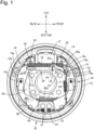
Fig. 1 is a front view of a drum brake (first embodiment). -
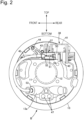
Fig. 2 is a rear view of the drum brake (first embodiment). -
Fig. 3 is a block diagram for illustrating a configuration for controlling an electric actuator (first embodiment). -
Fig. 4 is a flowchart for illustrating a control process at the time of the parking brake (first embodiment). -
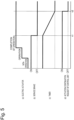
Fig. 5 is a timing chart for showing an example of an operation state of the electric actuator at the time of the parking brake, and changes in signals of a service brake, a timer, and an activation continuation request of a control unit (first embodiment). -
Fig. 6 is a timing chart for showing another example of an operation state of the electric actuator at the time of the parking brake, and changes in signals of the service brake, the timer, and the activation continuation request of the control unit (first embodiment). -
- 17 wheel cylinder
- 34 parking brake lever
- 37 brake cable
- 38 electric actuator
- 66 hydraulic pressure sensor serving as service brake detection means
- B drum brake
- C control unit
- An embodiment of the present invention is described with reference to the accompanying
Fig. 1 to Fig. 6 . - First, in
Fig. 1 , a drum brake B is provided on a vehicle wheel of a four-wheeled vehicle, for example, a left rear wheel, and the drum brake B includes: a fixedback plate 13 having, in a center portion, a throughhole 12 for allowing anaxle 11 of the left rear wheel to pass therethrough; first andsecond brake shoes back plate 13 to be brought into slide contact with an inner periphery of abrake drum 14 that rotates together with the left rear wheel; awheel cylinder 17 fixed to theback plate 13 to exert a force for causing the first andsecond brake shoes second brake shoes brake drum 14; and returnsprings 19 provided between the first andsecond brake shoes - The first and
second brake shoes second webs brake drum 14; first andsecond rims second webs second linings second rims - An
anchor plate 21 serving as a fulcrum at the time of expansion and contraction of the first andsecond brake shoes back plate 13 to rotatably support one end portion (lower end portion in this embodiment) of each of the first andsecond webs wheel cylinder 17 is fixed to theback plate 13 between the other end portions of the first andsecond brake shoes second brake shoes anchor plate 21 as a fulcrum, and outer end portions of a pair ofpistons 20 provided in thewheel cylinder 17 are arranged to be opposed to the other end portions (upper end portions in this embodiment) of the first andsecond webs - A
coil spring 22 that urges the one end portions of the first andsecond webs anchor plate 21 side is provided between the one end portions of the first andsecond webs return springs 19 that urge the first andsecond brake shoes second webs - The braking gap automatic adjustment means 18 includes: a contraction
position regulating strut 24 which is formed between the first andsecond webs second brake shoes gear 23; an adjustinglever 25 which has afeed claw 25a that is engaged with the adjustinggear 23 and which is rotatably supported by thesecond web 16a of thesecond brake shoe 16 of the first andsecond brake shoes spring 26 that urges the adjustinglever 25 to rotate to the side on which the adjustinggear 23 rotates in a direction of extending the contractionposition regulating strut 24. - The contraction
position regulating strut 24 regulates the contraction positions of the first andsecond brake shoes first rod 27 having a first engaging andcoupling portion 27a that is engaged with a position closer to the other end portion of thefirst web 15a included in thefirst brake shoe 15 of the first andsecond brake shoes second rod 28 which has a second engaging andcoupling portion 28a that is engaged with a position closer to the other end portion of thesecond web 16a included in thesecond brake shoe 16 and which is arranged coaxially with thefirst rod 27; and an adjustingbolt 29 having one end portion that is inserted into thefirst rod 27 to be relatively movable in an axis direction and having the other end portion that is threadedly engaged with thesecond rod 28 coaxially. The adjustinggear 23 is formed on an outer periphery of the adjustingbolt 29 to be arranged between the first andsecond rods - A first locking recess 30 for engaging the first engaging and
coupling portion 27a is formed on a side edge facing theaxle 11 side closer to the other end portion of thefirst web 15a, and a second locking recess 31 for engaging the second engaging andcoupling portion 28a is formed on a side edge facing theaxle 11 side closer to the other end portion of thesecond web 16a. - The adjusting
lever 25 having thefeed claw 25a that is engaged with the adjustinggear 23 is rotatably supported by thesecond web 16a through the intermediation of asupport shaft 32, and the adjustingspring 26 is provided between thesecond web 16a and the adjustinglever 25. Further, the spring force of the adjustingspring 26 is set to be smaller than the spring force of thereturn springs 19. - In the braking gap automatic adjustment means 18, at the time of causing the first and
second brake shoes wheel cylinder 17, when the first andsecond brake shoes second linings lever 25 rotates about the axis of thesupport shaft 32 due to the spring force of the adjustingspring 26. As a result, the effective length of the contractionposition regulating strut 24 is corrected to be increased in accordance with the rotation of the adjustinggear 23. - Incidentally, the drum brake B includes a
parking brake lever 34 capable of generating a parking brake force in accordance with the operation, and theparking brake lever 34 is arranged to overlap with a part of thefirst web 15a in thefirst brake shoe 15 in front view (direction illustrated inFig. 1 ) in a direction along the rotation axis of thebrake drum 14 and is extended long along a longitudinal direction of thefirst web 15a. - An
engaging piece 36 fixed to one end portion of abrake cable 37 is engaged with one end portion (lower end portion in this embodiment) of theparking brake lever 34, and the other end portion (upper end portion in this embodiment) of theparking brake lever 34 is coupled to the other end portion of thefirst web 15a in thefirst brake shoe 15 through the intermediation of apin 35. - When the parking brake of a vehicle operates, the
parking brake lever 34 is driven to rotate in a counterclockwise direction ofFig. 1 through the use of thepin 35 as a fulcrum by the pulling force input from thebrake cable 37. Due to the rotation of theparking brake lever 34, a force in a direction in which thesecond lining 16c included in thebrake shoe 16 is brought into pressure contact with the inner periphery of thebrake drum 14 acts on thesecond brake shoe 16 via the contractionposition regulating strut 24. Further, when theparking brake lever 34 is continuously driven to rotate in the counterclockwise direction ofFig. 1 , theparking brake lever 34 rotates through the use of the engagement portion with the first engaging andcoupling portion 27a of the contractionposition regulating strut 24 as a fulcrum. Then, thefirst brake shoe 15 operates to expand through the intermediation of thepin 35, and thefirst lining 15c of thefirst brake shoe 15 is brought into pressure contact with the inner periphery of thebrake drum 14. That is, theparking brake lever 34 operates to an operation position at which the first andsecond linings second brake shoes brake drum 14, and under this state, a parking brake state is obtained. - In addition, when the application of the rotational drive force to the
parking brake lever 34 is stopped by loosening thebrake cable 37, theparking brake lever 34 returns to a non-operation position together with the first andsecond brake shoes brake drum 14, and theparking brake lever 34 is urged toward the non-operation position side. - Also referring to
Fig. 2 , thebrake cable 37 is pulled by the power exerted by anelectric actuator 38, and theelectric actuator 38 includes: ascrew shaft 39 coupled to thebrake cable 37; anactuator case 40 that supports thescrew shaft 39 so that thescrew shaft 39 can reciprocate in the axis direction while blocking the rotation thereof; anelectric motor 41 accommodated in theactuator case 40 to freely rotate in forward and backward directions; and a motion conversion mechanism (not shown) that is accommodated in theactuator case 40 to be provided between theelectric motor 41 and thescrew shaft 39 while enabling the rotary motion generated in theelectric motor 41 to be converted into the linear motion of thescrew shaft 39. - The
actuator case 40 of theelectric actuator 38 is mounted to theback plate 13 on an opposite side of thewheel cylinder 17 through the intermediation of a mountingmember 43. The mountingmember 43 is fixed to theactuator case 40, and the mountingmember 43 is fastened to theback plate 13 with a plurality of, for example, threebolts 44. - The
screw shaft 39 of theelectric actuator 38 is coupled to thebrake cable 37 through the intermediation of a cable joint 51, and the coupling portion between thescrew shaft 39 and thebrake cable 37 is covered with aprotective cylinder 50 connected to theactuator case 40. - A
tubular portion 13a is integrally provided to project from a front portion along a vehicle front-and-rear direction of a lower portion of theback plate 13, and thebrake cable 37 is introduced into theback plate 13 from thetubular portion 13a. In addition, thebrake cable 37 is covered with anouter cable 45 formed by winding an iron wire in a coil shape between theprotective cylinder 50 and thetubular portion 13a. An end portion of theouter cable 45 on theelectric actuator 38 side is mounted to theprotective cylinder 50 through the intermediation of aguide tube 52, and an end portion of theouter cable 45 on theback plate 13 side is mounted to thetubular portion 13a through the intermediation of aguide tube 53. - In addition, a holding
plate 46 that sandwiches theanchor plate 21 with theback plate 13 is mounted to the lower portion of theback plate 13 with a pair ofrivets 47 together with theanchor plate 21 between the one end portions of the first andsecond webs guide portion 46a that guides thebrake cable 37 is integrally formed on the holdingplate 46 to have a substantially U-shaped transverse sectional shape. - In
Fig. 3 , the electric power of abattery 61 is supplied to theelectric motor 41 in theelectric actuator 38 through adrive circuit 62, and the operation of theelectric motor 41, that is, the operation of thedrive circuit 62 is controlled by a control unit C. Instruction means 63 for detecting that a vehicle user has performed an operation for obtaining the parking brake state by operation of theelectric actuator 38 and outputting a signal for instructing theelectric actuator 38 on the start of the operation is connected to the control unit C. - In addition, the drum brake B generates a brake force when the
wheel cylinder 17 operates in response to the operation input of the vehicle user at the time of the service brake. When the vehicle user steps on abrake pedal 64, the brake hydraulic pressure output from amaster cylinder 65 acts on thewheel cylinder 17. Ahydraulic pressure sensor 66 serving as a service brake detection means for detecting whether or not the service brake has been applied is inserted in ahydraulic pressure path 67 connecting themaster cylinder 65 and themaster cylinder 65 to detect the brake hydraulic pressure, and the brake hydraulic pressure detected by thehydraulic pressure sensor 66 is input to the control unit C. - The control unit C performs the control in accordance with the process illustrated in
Fig. 4 at the time of the parking brake. In Step S1, a determination is made on whether or not theelectric actuator 38 is in an operation state. When it is determined that theelectric actuator 38 is in the operation state, an activation continuation request of the control unit C is turned on in Step S2, and it is checked in Step S3 whether or not the application operation of theelectric actuator 38 has been completed. When the completion of the application operation of theelectric actuator 38 is confirmed, the flow proceeds to Step S4. In Step S4, a first predetermined time is set, and the brake hydraulic pressure detected by thehydraulic pressure sensor 66 is acquired in Step S5. After that, in Step S6, determination is made on, based on the brake hydraulic pressure, whether or not the vehicle is in a service brake state. - When it is determined that the vehicle is in the service brake state based on the determination in Step S6, the flow returns from Step S6 to Step S4. When it is determined that the vehicle is not in the service brake state, the flow proceeds from Step S6 to Step S7, and time is counted.
- When it is determined, in Step S8 following the count in Step S7, that the first predetermined time has elapsed, the flow proceeds to Step S9, and the activation continuation request of the control unit C is turned off to stop the operation of the control unit C.
- In addition, when it is determined in Step S8 that the first predetermined time has not elapsed, the flow proceeds from Step S8 to Step
S 10, and the brake hydraulic pressure detected by thehydraulic pressure sensor 66 is acquired. In Step S11 thereafter, a determination is made on, based on the brake hydraulic pressure, whether or not the vehicle is in the service brake state. When it is determined in Step S11 that the vehicle is not in the service brake state, the flow returns from Step S11 to Step S7. When it is determined that the vehicle is in the service brake state, the flow proceeds from Step S11 to Step S12, and the previous count value is reset. - In Step S13 following Step S12, a second predetermined time is set. The second predetermined time is the same as the first predetermined time in this embodiment. After the second predetermined time is set in Step S13, the flow proceeds to Step S14, and time is recounted to determine whether or not the second predetermined time has elapsed in Step S15. When the second predetermined time has not elapsed, the flow returns to Step S14. When it is confirmed that the second predetermined time has elapsed, the flow proceeds from Step S15 to Step S9.
- According to a such control process, after the completion of the application operation of the
electric actuator 38, the control unit C starts to count in response to the end of the detection of the service brake by thehydraulic pressure sensor 66 and stops the operation of the control unit C after an elapse of the first predetermined time from the start of the count. That is, as shown inFig. 5 , when theelectric actuator 38 is changed from the non-operation state to the operation completion state through the operation state to obtain the parking brake state in the service brake state, the activation continuation request of the control unit C is in an ON state. When the service brake state is ended at a time t1, the timer starts the count. At a time t2 at which the first predetermined time has elapsed from the time t1, the activation continuation request of the control unit C is turned off, and the control unit C stops the operation thereof. - In addition, the control unit C resets the count in response to the detection of application of the service brake by the
hydraulic pressure sensor 66 in the middle of time passage by the count started in response to the end of the detection of the service brake and starts recount. After an elapse of the second predetermined time from the start of the recount, the control unit C stops the operation thereof. That is, as shown inFig. 6 , when the service brake state is ended at a time t3, the timer starts to count, and a count value is reset when the service brake state is obtained at a time t4 at which the time less than the first predetermined time has elapsed from the time t3. When the service brake state is ended at a time t5 thereafter, the recount by the timer is performed. At a time t6 at which the second predetermined time has elapsed, the activation continuation request of the control unit C is turned off, and the control unit C stops the operation thereof. - Next, the action of this embodiment is described. After the completion of the application operation of the
electric actuator 38, the control unit C starts to count in response to the end of the detection of the service brake by thehydraulic pressure sensor 66 serving as the service brake detection means for detecting whether or not the service brake has been applied and stops the operation of the control unit C after an elapse of the first predetermined time from the start of the count. As a result, the load on thebattery 61 can be reduced by preventing the control unit C from being kept activated for a period of time that is longer than necessary. - In addition, the control unit C resets the count in response to the detection of application of the service brake by the
hydraulic pressure sensor 66 in the middle of time passage by the count and starts recount. After an elapse of the second predetermined time from the start of the recount, the control unit C stops the operation thereof. As a result, when there is an additional operation input of the vehicle user after the end of the service brake, the increase control of the parking brake force can be performed. - Further, the first predetermined time and the second predetermined time are set to be the same. As a result, the increase control of the parking brake force can be reliably performed additionally.
- In addition, as the service brake detection means, the
hydraulic pressure sensor 66 used in ordinary brake hydraulic pressure control is used. As a result, the use of a special sensor is made unnecessary to suppress an increase in the number of parts. - Further, the
electric actuator 38 for obtaining the parking brake is attached to the drum brake B. As a result, the present invention can be suitably applied to the drum brake B having theelectric actuator 38 attached thereto. - The embodiment of the present invention has been described. However, the present invention is not limited to the above-mentioned embodiment. Various changes in design can be made without departing from the scope of the present invention which is defined in the appended claims.
Claims (5)
- An electric parking brake device which enables a service brake and a parking brake wherein the service brake generates a brake force in accordance with an operation input of a vehicle user, and wherein the parking brake generates a brake force with the function of an electric actuator (38) having operation controlled by a control unit (C), comprising service brake detection means (66) connected to the control unit (C) to detect whether or not the service brake has been applied after completion of application operation of the electric actuator (38),
characterised in that
the control unit (C) starts to count in response to an end of detection of the service brake by the service brake detection means (66) and stops the control of the parking brake by the control unit (C) after an elapse of a first predetermined time from the start of the count. - The electric parking brake device according to claim 1, wherein the control unit (C) resets the count in response to the detection of application of the service brake by the service brake detection means (66) in the middle of time passage by the count and starts recount, and stops the control of the parking brake by the control unit (C) after an elapse of a second predetermined time from the start of the recount.
- The electric parking brake device according to claim 2, wherein the first predetermined time and the second predetermined time are set to be the same.
- The electric parking brake device according to any one of claims 1 to 3, wherein the service brake detection means is a hydraulic pressure sensor (66) configured to detect a brake hydraulic pressure for obtaining a brake force by the service brake.
- The electric parking brake device according to any one of claims 1 to 4, wherein the electric actuator (38) coupled to a brake cable (37) to drive a parking brake lever (34) is attached to a drum brake (B) including a wheel cylinder (17) configured to generate the brake force by the service brake, the parking brake lever (34) configured to operate to obtain the brake force by the parking brake, and the brake cable (37) coupled to the parking brake lever (34).
Applications Claiming Priority (2)
| Application Number | Priority Date | Filing Date | Title |
|---|---|---|---|
| JP2020043291 | 2020-03-12 | ||
| PCT/JP2020/047373 WO2021181809A1 (en) | 2020-03-12 | 2020-12-18 | Electric parking brake device |
Publications (3)
| Publication Number | Publication Date |
|---|---|
| EP4119811A1 EP4119811A1 (en) | 2023-01-18 |
| EP4119811A4 EP4119811A4 (en) | 2023-08-30 |
| EP4119811B1 true EP4119811B1 (en) | 2024-09-04 |
Family
ID=77671535
Family Applications (1)
| Application Number | Title | Priority Date | Filing Date |
|---|---|---|---|
| EP20923792.4A Active EP4119811B1 (en) | 2020-03-12 | 2020-12-18 | Electric parking brake device |
Country Status (6)
| Country | Link |
|---|---|
| US (1) | US20230150466A1 (en) |
| EP (1) | EP4119811B1 (en) |
| JP (1) | JP7488883B2 (en) |
| KR (1) | KR102786687B1 (en) |
| CN (1) | CN115279634B (en) |
| WO (1) | WO2021181809A1 (en) |
Family Cites Families (36)
| Publication number | Priority date | Publication date | Assignee | Title |
|---|---|---|---|---|
| US4629043A (en) * | 1983-01-31 | 1986-12-16 | Mazda Motor Corporation | Electric parking brake system for a vehicle |
| JPH08198100A (en) * | 1995-01-27 | 1996-08-06 | Mitsubishi Motors Corp | Parking brake safety device |
| US6325471B1 (en) * | 2000-03-09 | 2001-12-04 | Ford Global Technologies, Inc. | Brake-by-wire system having conditioned brake boost termination at key off |
| JP3708011B2 (en) * | 2000-09-13 | 2005-10-19 | トヨタ自動車株式会社 | Control device for vehicle brake |
| US6959794B2 (en) * | 2003-05-30 | 2005-11-01 | Goodrich Corporation | Low power parking brake force adjustment apparatus and method for electrically actuated brake systems |
| JP4333305B2 (en) * | 2003-09-24 | 2009-09-16 | マツダ株式会社 | Electric parking brake system |
| JP4618534B2 (en) * | 2004-03-31 | 2011-01-26 | 日立オートモティブシステムズ株式会社 | Electric brake device |
| EP1747128B1 (en) * | 2004-05-18 | 2009-06-17 | Continental Automotive GmbH | Parking brake system equipped with a sensor |
| JP2006131151A (en) * | 2004-11-08 | 2006-05-25 | Toyota Motor Corp | Electric parking brake device |
| JP2006298094A (en) | 2005-04-19 | 2006-11-02 | Nissan Motor Co Ltd | Vehicle stop holding device |
| US7524000B2 (en) * | 2006-12-04 | 2009-04-28 | The Boeing Company | Brake status indicator control for an electric brake system of a vehicle |
| JP4752781B2 (en) * | 2007-02-01 | 2011-08-17 | トヨタ自動車株式会社 | Electric parking brake control device, electric parking brake device, and control method of electric parking brake control device |
| JP4985448B2 (en) * | 2008-02-13 | 2012-07-25 | 株式会社アドヴィックス | Parking brake control device |
| JP2012035773A (en) * | 2010-08-09 | 2012-02-23 | Denso Corp | Parking brake control device |
| KR101251771B1 (en) * | 2010-12-02 | 2013-04-05 | 기아자동차주식회사 | Control Method for Parking Release Apparatus of Shift by Wire type Shifting Device |
| JP2013071521A (en) * | 2011-09-27 | 2013-04-22 | Advics Co Ltd | Parking brake control apparatus |
| DE102011116906A1 (en) * | 2011-10-25 | 2013-04-25 | Wabco Gmbh | Brake method and braking device for a vehicle, hydraulic brake system and vehicle with it |
| JP5737224B2 (en) * | 2012-05-28 | 2015-06-17 | 株式会社アドヴィックス | Brake device for vehicle |
| JP5894033B2 (en) * | 2012-07-30 | 2016-03-23 | 富士重工業株式会社 | Vehicle control device |
| JP6076023B2 (en) * | 2012-10-12 | 2017-02-08 | Ntn株式会社 | Electric parking brake device and electric brake device |
| JP2014205391A (en) | 2013-04-11 | 2014-10-30 | 日野自動車株式会社 | Electric parking brake system |
| JP6227333B2 (en) * | 2013-08-30 | 2017-11-08 | 日立オートモティブシステムズ株式会社 | Brake system |
| DE112014006308T5 (en) * | 2014-01-31 | 2016-11-17 | Hitachi Automotive Systems, Ltd. | braking system |
| JP6297883B2 (en) * | 2014-03-28 | 2018-03-20 | マツダ株式会社 | Electric brake device |
| US9228654B2 (en) * | 2014-04-11 | 2016-01-05 | Allison Transmission, Inc. | System and method for automatic neutral and automatic return-to-range for use with an automatic transmission |
| US10252707B2 (en) * | 2014-04-24 | 2019-04-09 | Hitachi Automotive Systems, Ltd. | Brake control system, brake system, and brake hydraulic pressure generating method |
| KR102167194B1 (en) * | 2014-05-28 | 2020-10-20 | 현대모비스 주식회사 | Electrical parking brake for vehicle and control method thereof |
| JP2016011081A (en) * | 2014-06-30 | 2016-01-21 | 株式会社ハイレックスコーポレーション | Electric parking brake control device |
| JP6276133B2 (en) * | 2014-07-31 | 2018-02-07 | 日立オートモティブシステムズ株式会社 | Electric parking brake device |
| JP6695753B2 (en) * | 2016-07-12 | 2020-05-20 | 日信工業株式会社 | Brake device for vehicle |
| KR102556617B1 (en) * | 2016-09-05 | 2023-07-19 | 에이치엘만도 주식회사 | Electronic control brake system in a vehicle and control method thereof |
| CN106627547B (en) * | 2016-11-17 | 2019-01-29 | 广州汽车集团股份有限公司 | Electronic brake system, method for starting and the vehicle of compatible automatic parking function |
| JP7056301B2 (en) * | 2018-03-26 | 2022-04-19 | 株式会社アドヴィックス | Braking control device |
| DE102019200955A1 (en) * | 2019-01-25 | 2020-07-30 | Robert Bosch Gmbh | Procedure for activating and deactivating a control unit |
| DE102021206182A1 (en) * | 2021-06-17 | 2022-12-22 | Continental Automotive Technologies GmbH | Procedure for backing up brake fluid |
| KR20230021845A (en) * | 2021-08-06 | 2023-02-14 | 에이치엘만도 주식회사 | Electronic parking brake system and control method thereof |
-
2020
- 2020-12-18 WO PCT/JP2020/047373 patent/WO2021181809A1/en not_active Ceased
- 2020-12-18 CN CN202080098408.0A patent/CN115279634B/en active Active
- 2020-12-18 US US17/910,662 patent/US20230150466A1/en active Pending
- 2020-12-18 EP EP20923792.4A patent/EP4119811B1/en active Active
- 2020-12-18 JP JP2022505770A patent/JP7488883B2/en active Active
- 2020-12-18 KR KR1020227031326A patent/KR102786687B1/en active Active
Also Published As
| Publication number | Publication date |
|---|---|
| EP4119811A1 (en) | 2023-01-18 |
| JP7488883B2 (en) | 2024-05-22 |
| WO2021181809A1 (en) | 2021-09-16 |
| JPWO2021181809A1 (en) | 2021-09-16 |
| EP4119811A4 (en) | 2023-08-30 |
| CN115279634B (en) | 2024-05-10 |
| KR102786687B1 (en) | 2025-03-25 |
| US20230150466A1 (en) | 2023-05-18 |
| KR20220133302A (en) | 2022-10-04 |
| CN115279634A (en) | 2022-11-01 |
Similar Documents
| Publication | Publication Date | Title |
|---|---|---|
| JP4985448B2 (en) | Parking brake control device | |
| US6655507B2 (en) | Electrically operated parking brake apparatus | |
| KR102051195B1 (en) | Brake control device | |
| JP5234266B2 (en) | Disc brake device | |
| US20230070909A1 (en) | Vehicle control apparatus, vehicle control method, and vehicle control system | |
| EP3135548B1 (en) | Brake device | |
| JP5104370B2 (en) | Parking brake control device | |
| JP7061681B2 (en) | Electric brakes and controls | |
| US9035591B2 (en) | Control method of electronic parking brake system | |
| JP6596294B2 (en) | Brake device for vehicle | |
| JP6562811B2 (en) | Brake device for vehicle | |
| EP4119811B1 (en) | Electric parking brake device | |
| EP4119812B1 (en) | Electric parking brake device | |
| JP4719700B2 (en) | Freezing detection device in electric parking brake device | |
| JP3943856B2 (en) | Freezing release device in electric parking brake device | |
| JP2007182227A5 (en) | ||
| JP7526254B2 (en) | Electric parking brake device | |
| EP3998415B1 (en) | Vehicle drum brake | |
| JP4657852B2 (en) | Electric parking brake device | |
| JP7431939B2 (en) | Electric parking brake device for vehicles | |
| JP7591032B2 (en) | Electric parking brake device | |
| JP2008241005A (en) | Electric parking brake device | |
| JP2018075855A (en) | Brake device for vehicle |
Legal Events
| Date | Code | Title | Description |
|---|---|---|---|
| STAA | Information on the status of an ep patent application or granted ep patent |
Free format text: STATUS: THE INTERNATIONAL PUBLICATION HAS BEEN MADE |
|
| PUAI | Public reference made under article 153(3) epc to a published international application that has entered the european phase |
Free format text: ORIGINAL CODE: 0009012 |
|
| STAA | Information on the status of an ep patent application or granted ep patent |
Free format text: STATUS: REQUEST FOR EXAMINATION WAS MADE |
|
| 17P | Request for examination filed |
Effective date: 20220912 |
|
| AK | Designated contracting states |
Kind code of ref document: A1 Designated state(s): AL AT BE BG CH CY CZ DE DK EE ES FI FR GB GR HR HU IE IS IT LI LT LU LV MC MK MT NL NO PL PT RO RS SE SI SK SM TR |
|
| RAP3 | Party data changed (applicant data changed or rights of an application transferred) |
Owner name: HITACHI ASTEMO UEDA, LTD. Owner name: HITACHI ASTEMO, LTD. |
|
| DAV | Request for validation of the european patent (deleted) | ||
| DAX | Request for extension of the european patent (deleted) | ||
| A4 | Supplementary search report drawn up and despatched |
Effective date: 20230728 |
|
| RIC1 | Information provided on ipc code assigned before grant |
Ipc: B60T 8/17 20060101ALI20230724BHEP Ipc: B60T 13/74 20060101ALI20230724BHEP Ipc: F16D 125/64 20120101ALI20230724BHEP Ipc: F16D 125/60 20120101ALI20230724BHEP Ipc: F16D 121/24 20120101ALI20230724BHEP Ipc: F16D 65/22 20060101ALI20230724BHEP Ipc: F16D 63/00 20060101ALI20230724BHEP Ipc: F16D 51/22 20060101AFI20230724BHEP |
|
| RAP1 | Party data changed (applicant data changed or rights of an application transferred) |
Owner name: HITACHI ASTEMO, LTD. |
|
| GRAP | Despatch of communication of intention to grant a patent |
Free format text: ORIGINAL CODE: EPIDOSNIGR1 |
|
| STAA | Information on the status of an ep patent application or granted ep patent |
Free format text: STATUS: GRANT OF PATENT IS INTENDED |
|
| INTG | Intention to grant announced |
Effective date: 20240429 |
|
| GRAS | Grant fee paid |
Free format text: ORIGINAL CODE: EPIDOSNIGR3 |
|
| GRAA | (expected) grant |
Free format text: ORIGINAL CODE: 0009210 |
|
| STAA | Information on the status of an ep patent application or granted ep patent |
Free format text: STATUS: THE PATENT HAS BEEN GRANTED |
|
| AK | Designated contracting states |
Kind code of ref document: B1 Designated state(s): AL AT BE BG CH CY CZ DE DK EE ES FI FR GB GR HR HU IE IS IT LI LT LU LV MC MK MT NL NO PL PT RO RS SE SI SK SM TR |
|
| REG | Reference to a national code |
Ref country code: GB Ref legal event code: FG4D |
|
| REG | Reference to a national code |
Ref country code: CH Ref legal event code: EP |
|
| REG | Reference to a national code |
Ref country code: IE Ref legal event code: FG4D |
|
| REG | Reference to a national code |
Ref country code: DE Ref legal event code: R096 Ref document number: 602020037349 Country of ref document: DE |
|
| REG | Reference to a national code |
Ref country code: LT Ref legal event code: MG9D |
|
| REG | Reference to a national code |
Ref country code: NL Ref legal event code: MP Effective date: 20240904 |
|
| PG25 | Lapsed in a contracting state [announced via postgrant information from national office to epo] |
Ref country code: NO Free format text: LAPSE BECAUSE OF FAILURE TO SUBMIT A TRANSLATION OF THE DESCRIPTION OR TO PAY THE FEE WITHIN THE PRESCRIBED TIME-LIMIT Effective date: 20241204 |
|
| PG25 | Lapsed in a contracting state [announced via postgrant information from national office to epo] |
Ref country code: PL Free format text: LAPSE BECAUSE OF FAILURE TO SUBMIT A TRANSLATION OF THE DESCRIPTION OR TO PAY THE FEE WITHIN THE PRESCRIBED TIME-LIMIT Effective date: 20240904 Ref country code: GR Free format text: LAPSE BECAUSE OF FAILURE TO SUBMIT A TRANSLATION OF THE DESCRIPTION OR TO PAY THE FEE WITHIN THE PRESCRIBED TIME-LIMIT Effective date: 20241205 Ref country code: FI Free format text: LAPSE BECAUSE OF FAILURE TO SUBMIT A TRANSLATION OF THE DESCRIPTION OR TO PAY THE FEE WITHIN THE PRESCRIBED TIME-LIMIT Effective date: 20240904 |
|
| PG25 | Lapsed in a contracting state [announced via postgrant information from national office to epo] |
Ref country code: BG Free format text: LAPSE BECAUSE OF FAILURE TO SUBMIT A TRANSLATION OF THE DESCRIPTION OR TO PAY THE FEE WITHIN THE PRESCRIBED TIME-LIMIT Effective date: 20240904 |
|
| PG25 | Lapsed in a contracting state [announced via postgrant information from national office to epo] |
Ref country code: LV Free format text: LAPSE BECAUSE OF FAILURE TO SUBMIT A TRANSLATION OF THE DESCRIPTION OR TO PAY THE FEE WITHIN THE PRESCRIBED TIME-LIMIT Effective date: 20240904 |
|
| PG25 | Lapsed in a contracting state [announced via postgrant information from national office to epo] |
Ref country code: HR Free format text: LAPSE BECAUSE OF FAILURE TO SUBMIT A TRANSLATION OF THE DESCRIPTION OR TO PAY THE FEE WITHIN THE PRESCRIBED TIME-LIMIT Effective date: 20240904 |
|
| PG25 | Lapsed in a contracting state [announced via postgrant information from national office to epo] |
Ref country code: ES Free format text: LAPSE BECAUSE OF FAILURE TO SUBMIT A TRANSLATION OF THE DESCRIPTION OR TO PAY THE FEE WITHIN THE PRESCRIBED TIME-LIMIT Effective date: 20240904 Ref country code: RS Free format text: LAPSE BECAUSE OF FAILURE TO SUBMIT A TRANSLATION OF THE DESCRIPTION OR TO PAY THE FEE WITHIN THE PRESCRIBED TIME-LIMIT Effective date: 20241204 |
|
| PG25 | Lapsed in a contracting state [announced via postgrant information from national office to epo] |
Ref country code: RS Free format text: LAPSE BECAUSE OF FAILURE TO SUBMIT A TRANSLATION OF THE DESCRIPTION OR TO PAY THE FEE WITHIN THE PRESCRIBED TIME-LIMIT Effective date: 20241204 Ref country code: PL Free format text: LAPSE BECAUSE OF FAILURE TO SUBMIT A TRANSLATION OF THE DESCRIPTION OR TO PAY THE FEE WITHIN THE PRESCRIBED TIME-LIMIT Effective date: 20240904 Ref country code: NO Free format text: LAPSE BECAUSE OF FAILURE TO SUBMIT A TRANSLATION OF THE DESCRIPTION OR TO PAY THE FEE WITHIN THE PRESCRIBED TIME-LIMIT Effective date: 20241204 Ref country code: LV Free format text: LAPSE BECAUSE OF FAILURE TO SUBMIT A TRANSLATION OF THE DESCRIPTION OR TO PAY THE FEE WITHIN THE PRESCRIBED TIME-LIMIT Effective date: 20240904 Ref country code: HR Free format text: LAPSE BECAUSE OF FAILURE TO SUBMIT A TRANSLATION OF THE DESCRIPTION OR TO PAY THE FEE WITHIN THE PRESCRIBED TIME-LIMIT Effective date: 20240904 Ref country code: GR Free format text: LAPSE BECAUSE OF FAILURE TO SUBMIT A TRANSLATION OF THE DESCRIPTION OR TO PAY THE FEE WITHIN THE PRESCRIBED TIME-LIMIT Effective date: 20241205 Ref country code: FI Free format text: LAPSE BECAUSE OF FAILURE TO SUBMIT A TRANSLATION OF THE DESCRIPTION OR TO PAY THE FEE WITHIN THE PRESCRIBED TIME-LIMIT Effective date: 20240904 Ref country code: ES Free format text: LAPSE BECAUSE OF FAILURE TO SUBMIT A TRANSLATION OF THE DESCRIPTION OR TO PAY THE FEE WITHIN THE PRESCRIBED TIME-LIMIT Effective date: 20240904 Ref country code: BG Free format text: LAPSE BECAUSE OF FAILURE TO SUBMIT A TRANSLATION OF THE DESCRIPTION OR TO PAY THE FEE WITHIN THE PRESCRIBED TIME-LIMIT Effective date: 20240904 |
|
| REG | Reference to a national code |
Ref country code: AT Ref legal event code: MK05 Ref document number: 1720691 Country of ref document: AT Kind code of ref document: T Effective date: 20240904 |
|
| PG25 | Lapsed in a contracting state [announced via postgrant information from national office to epo] |
Ref country code: NL Free format text: LAPSE BECAUSE OF FAILURE TO SUBMIT A TRANSLATION OF THE DESCRIPTION OR TO PAY THE FEE WITHIN THE PRESCRIBED TIME-LIMIT Effective date: 20240904 |
|
| PG25 | Lapsed in a contracting state [announced via postgrant information from national office to epo] |
Ref country code: IS Free format text: LAPSE BECAUSE OF FAILURE TO SUBMIT A TRANSLATION OF THE DESCRIPTION OR TO PAY THE FEE WITHIN THE PRESCRIBED TIME-LIMIT Effective date: 20250104 Ref country code: PT Free format text: LAPSE BECAUSE OF FAILURE TO SUBMIT A TRANSLATION OF THE DESCRIPTION OR TO PAY THE FEE WITHIN THE PRESCRIBED TIME-LIMIT Effective date: 20250106 |
|
| PG25 | Lapsed in a contracting state [announced via postgrant information from national office to epo] |
Ref country code: RO Free format text: LAPSE BECAUSE OF FAILURE TO SUBMIT A TRANSLATION OF THE DESCRIPTION OR TO PAY THE FEE WITHIN THE PRESCRIBED TIME-LIMIT Effective date: 20240904 Ref country code: SM Free format text: LAPSE BECAUSE OF FAILURE TO SUBMIT A TRANSLATION OF THE DESCRIPTION OR TO PAY THE FEE WITHIN THE PRESCRIBED TIME-LIMIT Effective date: 20240904 |
|
| PG25 | Lapsed in a contracting state [announced via postgrant information from national office to epo] |
Ref country code: EE Free format text: LAPSE BECAUSE OF FAILURE TO SUBMIT A TRANSLATION OF THE DESCRIPTION OR TO PAY THE FEE WITHIN THE PRESCRIBED TIME-LIMIT Effective date: 20240904 Ref country code: AT Free format text: LAPSE BECAUSE OF FAILURE TO SUBMIT A TRANSLATION OF THE DESCRIPTION OR TO PAY THE FEE WITHIN THE PRESCRIBED TIME-LIMIT Effective date: 20240904 |
|
| PG25 | Lapsed in a contracting state [announced via postgrant information from national office to epo] |
Ref country code: CZ Free format text: LAPSE BECAUSE OF FAILURE TO SUBMIT A TRANSLATION OF THE DESCRIPTION OR TO PAY THE FEE WITHIN THE PRESCRIBED TIME-LIMIT Effective date: 20240904 |
|
| PG25 | Lapsed in a contracting state [announced via postgrant information from national office to epo] |
Ref country code: IT Free format text: LAPSE BECAUSE OF FAILURE TO SUBMIT A TRANSLATION OF THE DESCRIPTION OR TO PAY THE FEE WITHIN THE PRESCRIBED TIME-LIMIT Effective date: 20240904 Ref country code: SK Free format text: LAPSE BECAUSE OF FAILURE TO SUBMIT A TRANSLATION OF THE DESCRIPTION OR TO PAY THE FEE WITHIN THE PRESCRIBED TIME-LIMIT Effective date: 20240904 |
|
| REG | Reference to a national code |
Ref country code: DE Ref legal event code: R097 Ref document number: 602020037349 Country of ref document: DE |
|
| PG25 | Lapsed in a contracting state [announced via postgrant information from national office to epo] |
Ref country code: MC Free format text: LAPSE BECAUSE OF FAILURE TO SUBMIT A TRANSLATION OF THE DESCRIPTION OR TO PAY THE FEE WITHIN THE PRESCRIBED TIME-LIMIT Effective date: 20240904 |
|
| PG25 | Lapsed in a contracting state [announced via postgrant information from national office to epo] |
Ref country code: DK Free format text: LAPSE BECAUSE OF FAILURE TO SUBMIT A TRANSLATION OF THE DESCRIPTION OR TO PAY THE FEE WITHIN THE PRESCRIBED TIME-LIMIT Effective date: 20240904 |
|
| PLBE | No opposition filed within time limit |
Free format text: ORIGINAL CODE: 0009261 |
|
| STAA | Information on the status of an ep patent application or granted ep patent |
Free format text: STATUS: NO OPPOSITION FILED WITHIN TIME LIMIT |
|
| REG | Reference to a national code |
Ref country code: CH Ref legal event code: PL |
|
| 26N | No opposition filed |
Effective date: 20250605 |
|
| PG25 | Lapsed in a contracting state [announced via postgrant information from national office to epo] |
Ref country code: LU Free format text: LAPSE BECAUSE OF NON-PAYMENT OF DUE FEES Effective date: 20241218 |
|
| GBPC | Gb: european patent ceased through non-payment of renewal fee |
Effective date: 20241218 |
|
| PG25 | Lapsed in a contracting state [announced via postgrant information from national office to epo] |
Ref country code: SE Free format text: LAPSE BECAUSE OF FAILURE TO SUBMIT A TRANSLATION OF THE DESCRIPTION OR TO PAY THE FEE WITHIN THE PRESCRIBED TIME-LIMIT Effective date: 20240904 |
|
| REG | Reference to a national code |
Ref country code: BE Ref legal event code: MM Effective date: 20241231 |
|
| PG25 | Lapsed in a contracting state [announced via postgrant information from national office to epo] |
Ref country code: GB Free format text: LAPSE BECAUSE OF NON-PAYMENT OF DUE FEES Effective date: 20241218 Ref country code: BE Free format text: LAPSE BECAUSE OF NON-PAYMENT OF DUE FEES Effective date: 20241231 |
|
| PG25 | Lapsed in a contracting state [announced via postgrant information from national office to epo] |
Ref country code: CH Free format text: LAPSE BECAUSE OF NON-PAYMENT OF DUE FEES Effective date: 20241231 |
|
| PG25 | Lapsed in a contracting state [announced via postgrant information from national office to epo] |
Ref country code: IE Free format text: LAPSE BECAUSE OF NON-PAYMENT OF DUE FEES Effective date: 20241218 |
|
| PGFP | Annual fee paid to national office [announced via postgrant information from national office to epo] |
Ref country code: DE Payment date: 20251028 Year of fee payment: 6 |
|
| PGFP | Annual fee paid to national office [announced via postgrant information from national office to epo] |
Ref country code: FR Payment date: 20251110 Year of fee payment: 6 |