EP4119810A1 - Outer joint member for plunging type constant velocity universal joint, plunging type constant velocity universal joint, and coming-off prevention processing method - Google Patents
Outer joint member for plunging type constant velocity universal joint, plunging type constant velocity universal joint, and coming-off prevention processing method Download PDFInfo
- Publication number
- EP4119810A1 EP4119810A1 EP21768483.6A EP21768483A EP4119810A1 EP 4119810 A1 EP4119810 A1 EP 4119810A1 EP 21768483 A EP21768483 A EP 21768483A EP 4119810 A1 EP4119810 A1 EP 4119810A1
- Authority
- EP
- European Patent Office
- Prior art keywords
- joint member
- outer joint
- opening end
- constant velocity
- velocity universal
- Prior art date
- Legal status (The legal status is an assumption and is not a legal conclusion. Google has not performed a legal analysis and makes no representation as to the accuracy of the status listed.)
- Granted
Links
Images



Classifications
-
- F—MECHANICAL ENGINEERING; LIGHTING; HEATING; WEAPONS; BLASTING
- F16—ENGINEERING ELEMENTS AND UNITS; GENERAL MEASURES FOR PRODUCING AND MAINTAINING EFFECTIVE FUNCTIONING OF MACHINES OR INSTALLATIONS; THERMAL INSULATION IN GENERAL
- F16D—COUPLINGS FOR TRANSMITTING ROTATION; CLUTCHES; BRAKES
- F16D3/00—Yielding couplings, i.e. with means permitting movement between the connected parts during the drive
- F16D3/16—Universal joints in which flexibility is produced by means of pivots or sliding or rolling connecting parts
- F16D3/20—Universal joints in which flexibility is produced by means of pivots or sliding or rolling connecting parts one coupling part entering a sleeve of the other coupling part and connected thereto by sliding or rolling members
- F16D3/202—Universal joints in which flexibility is produced by means of pivots or sliding or rolling connecting parts one coupling part entering a sleeve of the other coupling part and connected thereto by sliding or rolling members one coupling part having radially projecting pins, e.g. tripod joints
- F16D3/205—Universal joints in which flexibility is produced by means of pivots or sliding or rolling connecting parts one coupling part entering a sleeve of the other coupling part and connected thereto by sliding or rolling members one coupling part having radially projecting pins, e.g. tripod joints the pins extending radially outwardly from the coupling part
- F16D3/2055—Universal joints in which flexibility is produced by means of pivots or sliding or rolling connecting parts one coupling part entering a sleeve of the other coupling part and connected thereto by sliding or rolling members one coupling part having radially projecting pins, e.g. tripod joints the pins extending radially outwardly from the coupling part having three pins, i.e. true tripod joints
-
- F—MECHANICAL ENGINEERING; LIGHTING; HEATING; WEAPONS; BLASTING
- F16—ENGINEERING ELEMENTS AND UNITS; GENERAL MEASURES FOR PRODUCING AND MAINTAINING EFFECTIVE FUNCTIONING OF MACHINES OR INSTALLATIONS; THERMAL INSULATION IN GENERAL
- F16D—COUPLINGS FOR TRANSMITTING ROTATION; CLUTCHES; BRAKES
- F16D3/00—Yielding couplings, i.e. with means permitting movement between the connected parts during the drive
- F16D3/16—Universal joints in which flexibility is produced by means of pivots or sliding or rolling connecting parts
- F16D3/20—Universal joints in which flexibility is produced by means of pivots or sliding or rolling connecting parts one coupling part entering a sleeve of the other coupling part and connected thereto by sliding or rolling members
- F16D3/22—Universal joints in which flexibility is produced by means of pivots or sliding or rolling connecting parts one coupling part entering a sleeve of the other coupling part and connected thereto by sliding or rolling members the rolling members being balls, rollers, or the like, guided in grooves or sockets in both coupling parts
- F16D3/223—Universal joints in which flexibility is produced by means of pivots or sliding or rolling connecting parts one coupling part entering a sleeve of the other coupling part and connected thereto by sliding or rolling members the rolling members being balls, rollers, or the like, guided in grooves or sockets in both coupling parts the rolling members being guided in grooves in both coupling parts
- F16D3/226—Universal joints in which flexibility is produced by means of pivots or sliding or rolling connecting parts one coupling part entering a sleeve of the other coupling part and connected thereto by sliding or rolling members the rolling members being balls, rollers, or the like, guided in grooves or sockets in both coupling parts the rolling members being guided in grooves in both coupling parts the groove centre-lines in each coupling part lying on a cylinder co-axial with the respective coupling part
- F16D3/227—Universal joints in which flexibility is produced by means of pivots or sliding or rolling connecting parts one coupling part entering a sleeve of the other coupling part and connected thereto by sliding or rolling members the rolling members being balls, rollers, or the like, guided in grooves or sockets in both coupling parts the rolling members being guided in grooves in both coupling parts the groove centre-lines in each coupling part lying on a cylinder co-axial with the respective coupling part the joints being telescopic
-
- F—MECHANICAL ENGINEERING; LIGHTING; HEATING; WEAPONS; BLASTING
- F16—ENGINEERING ELEMENTS AND UNITS; GENERAL MEASURES FOR PRODUCING AND MAINTAINING EFFECTIVE FUNCTIONING OF MACHINES OR INSTALLATIONS; THERMAL INSULATION IN GENERAL
- F16D—COUPLINGS FOR TRANSMITTING ROTATION; CLUTCHES; BRAKES
- F16D3/00—Yielding couplings, i.e. with means permitting movement between the connected parts during the drive
- F16D3/16—Universal joints in which flexibility is produced by means of pivots or sliding or rolling connecting parts
- F16D3/20—Universal joints in which flexibility is produced by means of pivots or sliding or rolling connecting parts one coupling part entering a sleeve of the other coupling part and connected thereto by sliding or rolling members
- F16D3/202—Universal joints in which flexibility is produced by means of pivots or sliding or rolling connecting parts one coupling part entering a sleeve of the other coupling part and connected thereto by sliding or rolling members one coupling part having radially projecting pins, e.g. tripod joints
- F16D2003/2026—Universal joints in which flexibility is produced by means of pivots or sliding or rolling connecting parts one coupling part entering a sleeve of the other coupling part and connected thereto by sliding or rolling members one coupling part having radially projecting pins, e.g. tripod joints with trunnion rings, i.e. with tripod joints having rollers supported by a ring on the trunnion
-
- F—MECHANICAL ENGINEERING; LIGHTING; HEATING; WEAPONS; BLASTING
- F16—ENGINEERING ELEMENTS AND UNITS; GENERAL MEASURES FOR PRODUCING AND MAINTAINING EFFECTIVE FUNCTIONING OF MACHINES OR INSTALLATIONS; THERMAL INSULATION IN GENERAL
- F16D—COUPLINGS FOR TRANSMITTING ROTATION; CLUTCHES; BRAKES
- F16D2300/00—Special features for couplings or clutches
- F16D2300/12—Mounting or assembling
Definitions
- the present invention relates to an outer joint member for a plunging type constant velocity universal joint, a plunging type constant velocity universal joint, and a coming-off prevention processing method.
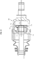
- the plunging type constant velocity universal joint there have been known, for example, a tripod type constant velocity universal joint of a roller type as illustrated in FIG. 18 and a double-offset constant velocity universal joint of a ball type as illustrated in FIG. 19 .
- a tripod type constant velocity universal joint 60 illustrated in FIG. 18 includes an outer joint member 61 including a plurality of track grooves 65 in an inner peripheral surface thereof, a tripod member 62 serving as an inner joint member, and rollers 63 serving as rolling elements provided to the tripod member 62.
- the rollers 63 roll along the track grooves 65 of the outer joint member 61 so that internal components including the rollers 63 and the tripod member 62 move in an axial direction X with respect to the outer joint member 61.
- the term "axial direction” here means a direction of a center axis O of the outer joint member 61 or a direction of any axis parallel to the center axis O. The same applies hereinafter.
- a double-offset constant velocity universal joint 70 illustrated in FIG. 19 includes an outer joint member 71 including a plurality of track grooves 75 in an inner peripheral surface thereof, an inner joint member 72 including a plurality of track grooves 76 in an outer peripheral surface thereof, a plurality of balls 73 serving as rolling elements arranged between the track grooves 75 and 76 of the outer joint member 71 and the inner joint member 72 which are opposed to each other, and a cage 74 that retains the balls 73 while being interposed between the inner peripheral surface of the outer joint member 71 and the outer peripheral surface of the inner joint member 72.
- the balls 73 roll along the track grooves 75 of the outer joint member 71 so that internal components including the balls 73, the inner joint member 72, and the cage 74 move in the axial direction X with respect to the outer joint member 71.
- Patent Literature 1 JP 4609050 B2
- a coming-off prevention structure for preventing the internal components from coming off is proposed. Specifically, pins are driven to an opening end surface of the outer joint member so that protruding portions are formed on inner surfaces of guide grooves, and rollers which are internal components are brought into abutment against the protruding portions, to thereby prevent the internal components from coming off.
- Patent Literature 1 JP 4609050 B2
- the protruding amount of the protruding portions is set to such a degree that getting over (press fitting) of the rollers or the balls is allowed.
- the present invention has an object to provide an outer joint member for a plunging type constant velocity universal joint, a plunging type constant velocity universal joint, and a coming-off prevention processing method capable of preventing coming off of internal components while suppressing occurrence of a contact mark or adhesion.
- an outer joint member for a plunging type constant velocity universal joint comprising a track groove configured to receive a rolling element in an inner peripheral surface thereof, the outer joint member being configured to transmit rotational torque while allowing angular displacement and axial displacement between the outer joint member and an inner joint member through intermediation of the rolling element
- the outer joint member comprising: a raised portion formed by caulking at an opening end side of the track groove so as to prevent coming-off of internal components comprising the rolling element and the inner joint member; a recess formed by caulking at an opening end surface corresponding to a portion at which the raised portion is formed; and an inlet inclined surface, which is inclined by 45° or more with respect to the opening end surface, and is formed at the opening end of the track groove adjacent to the raised portion, wherein the raised portion comprises a raised inclined surface inclined so as to increase a raised amount from the opening end side to a joint far side.
- the outer joint member for a plunging type constant velocity universal joint has the structural feature as described above, thereby being capable of avoiding formation of an end surface edge having an acute angle on the raised portion. With this, when the internal components are to be assembled to the outer joint member, occurrence of a contact mark or adhesion to the rolling element due to contact with the end surface edge can be suppressed.
- the inlet inclined surface be inclined with respect to the opening end surface in a range of from 60° or more and 70° or less.
- the recess has a shape having a pair of inclined surfaces provided at positions apart from each other in a direction along the track groove and inclined so as to approach each other toward a bottom portion of the recess as viewed from an axial direction.
- the recess is formed into such shape having a pair of inclined surfaces.
- a shape of the processing tool for forming the recess can be formed in a shape having a pair of side surfaces inclined so as to approach each other toward a distal end.
- the processing tool has such a shape, the distal end of the processing tool is easily pushed into the opening end surface of the outer joint member. With this, a load applied at the time of pushing the processing tool can be reduced, thereby being capable of improving durability of the processing tool.
- the raised portion may allow coming off of the internal components when a pull-out force larger than a coming-off force that may be generated at the time of an operation for assembling a joint is applied to the internal components.
- the outer joint member and the internal component can be separated away from each other after assembly, thereby improving operability of repair and maintenance.
- a plunging type constant velocity universal joint comprising: an outer joint member having a track groove formed in an inner peripheral surface thereof; a rolling element arranged in the track groove so as to be rollable; and an inner joint member configured to transmit rotational torque while allowing angular displacement and axial displacement between the inner joint member and the outer joint member through intermediation of the rolling element, wherein the plunging type constant velocity universal joint comprises, as the outer joint member, the outer joint member for a plunging type constant velocity universal joint according to the present invention.
- a coming-off prevention processing method of performing coming-off prevention processing for internal components comprising a rolling element and an inner joint member on an outer joint member for a plunging type constant velocity universal joint, the outer joint member comprising a track groove configured to receive a rolling element in an inner peripheral surface thereof, the outer joint member being configured to transmit rotational torque while allowing angular displacement and axial displacement between the outer joint member and an inner joint member through intermediation of the rolling element.
- the method comprises: forming an inlet inclined surface inclined by 45° or more with respect to the opening end surface of the outer joint member at an opening end of the track groove; and by forming a recess in the opening end surface by a caulking process, the opening end side of the track groove comprising at least the inlet inclined surface is raised to form a raised portion for preventing the internal component from coming off.
- the inlet inclined surface inclined by 45° or more with respect to the opening end surface of the outer joint member is formed on the opening end of the track groove, thereby being capable of avoiding formation of an end surface edge having an acute angle on the raised portion formed thereafter.
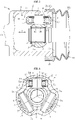
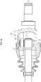
- FIG. 1 is a longitudinal sectional view of a tripod type constant velocity universal joint according to an embodiment of the present invention
- FIG. 2 is a transverse sectional view of the tripod type constant velocity universal joint according to this embodiment.
- a tripod type constant velocity universal joint 1 comprises, as main components, an outer joint member 2, a tripod member 3 serving as an inner joint member, and rollers 4 serving as rolling elements.
- the outer joint member 2 is a member formed in a cup shape having an opening portion at one end.
- three track grooves 5 extending in an axial direction are formed at equal intervals in a circumferential direction.
- Each of the track grooves 5 has roller guide surfaces 5a serving as rolling element guide surfaces opposed to each other.
- the term "axial direction" in the description related to the present invention means a center axis O of the outer joint member 2 or a direction X of any axis parallel to the center axis O (see FIG. 1 ).
- the tripod member 3 comprises a boss portion 6 having a center hole 6a, and three leg shafts 7 protruding from the boss portion 6 in a radial direction.
- the center hole 6a of the boss portion 6 has a female spline 6b fittable to a male spline 8b formed in an end portion of a shaft 8.
- the end portion of the shaft 8 is inserted into the center hole 6a so that the male spline 8b and the female spline 6b are fitted to each other, thereby coupling the shaft 8 and the tripod member 3 to each other so as to be integrally rotatable.
- a snap ring 9 is mounted to the end portion of the shaft 8 which protrudes from the center hole 6a, thereby preventing coming off of the shaft 8 from the tripod member 3 in the axial direction.
- a roller unit 14 comprising the roller 4 and the like is mounted to each of the leg shafts 7 of the tripod member 3.
- the roller unit 14 comprises the roller 4 serving as an outer ring, an inner ring 10 arranged on an inner side of the roller 4 and externally fitted to the leg shaft 7, and a large number of needle rollers 11 interposed between the roller 4 and the inner ring 10.
- the roller 4, the inner ring 10, and the needle rollers 11 are assembled to each other with washers 12 and 13 so as not to be separated away from each other.
- the rollers 4 are arranged in the track grooves 5 of the outer joint member 2.
- the rollers 4 roll along the roller guide surfaces 5a of the track grooves 5 so that internal components comprising the roller units 14 and the tripod member 3 are displaced in the axial direction with respect to the outer joint member 2.
- the transverse cross section of the leg shaft 7 is formed in a substantially elliptical shape so that the roller unit 14 can be inclined with respect to the axis of the leg shaft 7. With this, angular displacement in which the axis of the tripod member 3 is inclined with respect to the axis of the outer joint member 2 is allowed.
- the roller unit 14 also functions as a torque transmission member that transmits rotational torque between the tripod member 3 and the outer joint member 2 when the tripod member 3 rotates along with rotation of the shaft 8.
- the tripod type constant velocity universal joint 1 comprises a boot 15 for sealing the opening portion of the outer joint member 2.
- the boot 15 comprises a large-diameter end portion 15a, a small-diameter end portion (not shown), and a bellows portion 15c coupling the large-diameter end portion 15a and the small-diameter end portion to each other.
- the large-diameter end portion 15a is mounted to a boot mounting portion 2b formed on an opening end side of a radially outer surface of the outer joint member 2 by being fastened with a boot band 16.
- the small-diameter portion is mounted to a boot mounting portion (not shown) formed in a radially outer surface of the shaft 8 by being fastened with another boot band.
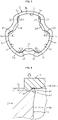
- FIG. 3 is an end view of the outer joint member 2 as viewed from the opening end side.
- raised portions 20 for preventing coming off of the internal components are formed on the opening end side of the track groove 5 of the outer joint member 2.
- the raised portion 20 is provided one by one on each roller guide surface 5a of each track groove 5.
- a recess 30 which is a tool mark given when the outer joint member 2 is caulked so as to form the raised portion 20.
- the recess 30 is formed in a rectangle (rectangular shape or square shape) as viewed from the axial direction, and is formed one by one so as to correspond to each raised portion 20 at an independent position (opening end surface 2a) which is not continuous with the track groove 5. It is not always required that the protruding amounts of the respective raised portions 20 be the same. The protruding amounts of the raised portions 20 may be made different for each outer joint member 2, each track groove 5, or each raised portion 20.
- FIG. 4 is a longitudinal sectional view of the outer joint member 2 taken along the axial direction at positions of the raised portions 20.
- the raised portion 20 protrudes inward from the roller guide surface 5a.
- the roller 4 which is the internal component is pushed from the opening end 2a side of the track groove 5 to the joint far side (lower side of FIG. 4 ).
- the roller 4 comes into contact with the raised portions 20 to restrict insertion of the roller 4 temporarily.
- the roller 4 is pushed into the track groove 5 against a restricting force of the raised portions 20, and the roller guide surfaces 5a opposed to each other are elasto-plastically deformed and expanded so that the roller 4 can get over the raised portions 20.
- the roller 4 is inserted into the far side of the track groove 5, and the internal component is assembled. After the internal component is assembled in this manner, movement of the roller 4 from the track groove 5 to an outside is restricted by the raised portions 20, thereby preventing coming off of the internal component.
- the coming-off prevention force by the raised portions 20 is set to be equal to or larger than a coming-off force that may be generated at the time of an operation of assembling the joint to a vehicle body or the like.
- the internal component does not come off from the outer joint member 2 by the coming-off force that may be generated at the time of an operation of assembling the joint.
- the raised portions 20 may allow the internal component to come off. Accordingly, the outer joint member and the internal component can be separated away from each other after assembling, thereby improving operability of repair and maintenance.
- the raised portions are formed as described below.
- the coming-off prevention structure and a coming-off prevention processing method of the outer joint member according to this embodiment are described.
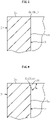
- FIG. 5 is a longitudinal sectional view of the track groove 5 before the raised portion 20 is formed. As illustrated in FIG. 5 , a corner portion having a substantially right angle formed by the opening end surface 2a of the outer joint member 2 and the track groove 5 is present at an opening end 5b of the track groove 5 (opening end 5b1 of the roller guide surface 5a) before the raised portion 20 is formed.
- the corner portion is subjected to cutting, for example, so that an inlet inclined surface 21 is formed at the opening end 5b as illustrated in FIG. 6 .
- the inlet inclined surface 21 may be formed by forging.
- the inlet inclined surface 21 is inclined to the radially inner side of the joint from the opening end surface 2a side of the outer joint member 2 toward the joint far side, and an inclination angle ⁇ of the inlet inclined surface 21 with respect to the opening end surface 2a of the outer joint member 2 is 45° or more (and less than 90°).
- the inlet inclined surface 21 be formed at least at the opening end 5b1 of the roller guide surface 5a with which the above-mentioned roller 4 comes into contact in the track groove 5. Further, the inlet inclined surface 21 may be provided at the opening end 5b of the entire track groove 5.
- the inlet inclined surface 21 herein is different from an inclined surface for preventing an interference of a shaft, which is generally provided in an outer joint member for a tripod type constant velocity universal joint.
- the inclined surface for preventing an interference of a shaft is an inclined surface 19 (see FIG.
- the inlet inclined surface 21 is an inclined surface provided at the opening end 5b of the track groove 5 separately from the inclined surface 19 for preventing an interference of a shaft.
- a processing tool 40 for caulking the raised portion is pressed against the opening end surface 2a of the outer joint member 2, and a raised portion forming portion 42 having a convex shape of the processing tool 40 is made to bite into the opening end surface 2a.
- a portion of the opening end surface 2a against which the processing tool 40 is pressed is a portion corresponding to a portion at which the inlet inclined surface 21 is formed.
- the processing tool 40 is pressed at a position away by 0.1 mm to 0.8 mm from an edge at which the inlet inclined surface 21 is formed to the radially outer side of the joint.
- the recess 30 which is a tool mark is formed in the opening end surface 2a, and a portion in the vicinity of the opening end 5b of the track groove 5 is plastically deformed so as to protrude to the radially inner side of the joint, thereby forming the raised portion 20.
- a raised inclined surface 22 inclined so as to increase the raised amount from the opening end 5b side of the track groove 5 toward the joint far side (lower side of FIG. 8 ) is formed.
- the raised inclined surface 22 is formed by raising the inlet inclined surface 21 formed in advance at the opening end 5b of the track groove 5 along with formation of the raised portion 20.
- the raised inclined surface 22 is formed on the raised portion 20 so that the end surface edge E having an acute angle as illustrated in FIG. 15 is not formed on the raised portion 20.
- the inlet inclined surface 21 is formed in advance at the opening end 5b of the track groove 5 before the formation of the raised portion 20, thereby being capable of avoiding formation of the end surface edge E having an acute angle at the raised portion 20. With this, occurrence of a contact mark or adhesion caused due to contact of the roller 4 with the end surface edge E can be avoided. That is, in the case of this embodiment, when the internal component is to be assembled to the outer joint member 2, as illustrated in FIG. 9 , the roller 4 is press-fitted into the track groove 5 while being in contact with the raised inclined surface 22 of the raised portion 20, thereby being capable of preventing a large contact pressure from being applied to the roller 4.
- the roller 4 is less liable to be inclined, and it becomes easy to assemble the internal component. As described above, according to the configuration of this embodiment, ease of assembly can be improved while suppressing occurrence of a contact mark or adhesion.
- the inclination angle ⁇ of the inlet inclined surface 21 is set to 45° or more so that a larger inclination angle ⁇ (see FIG. 9 ) with respect to the opening end surface 2a of the outer joint member 2 of the raised inclined surface 22 can be secured.
- the inclination angle ⁇ of the inlet inclined surface 21 is less than 45°, as illustrated in FIG. 16 , the inclination angle ⁇ of the raised inclined surface 22 also becomes smaller. In this case, the roller 4 is less likely to come into contact with the raised inclined surface 22, and thus making the raised inclined surface 22 difficult to exert the function as the guide surface for guiding the roller 4.
- the inclination angle ⁇ of the raised inclined surface 22 becomes smaller so that an edge angle ⁇ of the most protruding portion of the raised portion 20 is smaller than that in this embodiment (see FIG. 9 ).
- the contact pressure applied when the roller 4 comes into contact with the raised portion 20 increases. Accordingly, a contact mark is liable to be formed in the roller 4, or adhesion of the outer joint member to the roller 4 is liable to occur.
- the large inclination angle ⁇ of the raised inclined surface 22 can be secured.
- the roller guide function at the time of assembling the internal component can sufficiently be exerted, and a contact mark or adhesion can effectively be suppressed.
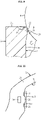
- FIG. 10 is an end view of a portion at which the raised portion 20 is formed and a periphery thereof in the outer joint member 2 according to this embodiment as viewed from the opening end surface 2a side.
- the inlet inclined surface 21 remains in a portion adjacent to the raised portion 20 in the opening end Sb1 of the roller guide surface 5a. This is because the inlet inclined surface 21 is formed in a range wider than a range of the raised portion 20 formed thereafter. As described above, the inlet inclined surface 21 is formed in the range wider than the range in which the raised portion 20 is formed so that the raised portion 20 can reliably be formed on the raised inclined surface 22, thereby being capable of achieving the above-described function or effect.
- the region in which the inlet inclined surface 21 remains may be on both sides of the raised portion 20 as illustrated in FIG. 10 or may be only one side of the raised portion 20.
- a method of forming the raised inclined surface 22 on the raised portion 20 by pressing the processing tool 40 against the raised portion 20 in the middle of formation as in the example illustrated in FIG. 17 is also conceivable.
- the inlet inclined surface 21 is not formed in advance at the opening end 5b of the track groove 5, and a part of projection of the raised portion 20 is restrained by the processing tool 40 at the time of forming the raised portion 20 to form the raised inclined surface 22.
- the inlet inclined surface 21 is formed in advance at the opening end 5b of the track groove 5.
- the raised inclined surface 22 can be formed without pressing the processing tool 40 against the raised portions 20, and caulking can be performed with a small pushing load. Accordingly, according to the processing method of this embodiment, a press machine or the like that applies a large load to the processing tool 40 becomes unnecessary. As a result, equipment cost can be reduced, and wear of the processing tool 40 can also be suppressed, thereby improving durability.
- the processing tool 40 for forming the raised portion 20 for example, the processing tool 40 as illustrated in FIG. 11 can be used.
- the processing tool 40 illustrated in FIG. 11 comprises a main body portion 41 having a rectangular parallelepiped or cubic shape, and the raised portion forming portion 42 having a triangular convex shape formed on the main body portion 41.
- the raised portion forming portion 42 comprises a pair of side surfaces 43 and 44 having a triangular shape provided at positions apart from each other in the width direction Z, and a front surface 45 and a rear surface 46 having a quadrangular shape (rectangular shape) provided between the side surfaces 43 and 44.
- a ridge line portion connecting the front surface 45 and the rear surface 46 to each other forms a distal end 47 of the raised portion forming portion 42.
- the distal end 47 of the raised portion forming portion 42 is pressed against the opening end surface 2a of the outer joint member 2. Then, the raised portion forming portion 42 is pushed into the opening end surface 2a so that the shape of the raised portion forming portion 42 is transferred onto the opening end surface 2a to form the recess 30, and the raised portion 20 is formed on the track groove 5 along with formation of the recess 30.
- the pair of side surfaces 43 and 44 of the raised portion forming portion 42 are arranged in parallel to each other as in the example illustrated in FIG. 11 , a load applied at the time of pushing the raised portion forming portion 42 tends to be larger.
- the pair of side surfaces 43 and 44 may be inclined so as to approach each other toward the distal end 47.
- the recess 30 formed using the processing tool 40 illustrated in FIG. 12 has the following shape.
- the recess 30 is formed into a shape having first and second inclined surfaces 51 and 52 having a triangular shape to which the pair of side surfaces 43 and 44 of the processing tool 40 are transferred, third and fourth inclined surfaces 53 and 54 having a quadrangular shape (trapezoidal shape) to which the front surface 45 and the rear surface 46 of the processing tool 40 are transferred, and a bottom portion 55 to which the distal end 47 of the processing tool 40 is transferred.
- the first inclined surface 51 and the second inclined surface 52 each having a triangular shape are provided at positions apart from each other in a direction Y along the track groove 5 as viewed from the axial direction, and are inclined so as to approach each other toward the bottom portion 55.
- the third inclined surface 53 and the fourth inclined surface 54 each having a quadrangular shape (trapezoidal shape) extend in the direction Y along the track groove 5, and are inclined so as to approach each other toward the bottom portion 55.
- the shape of the opening edge of the recess 30 be a rectangular shape or a square shape as illustrated in FIG. 13 , and may be a shape having a curved line or a folding line at a part (in this case, the shape of the fourth inclined surface 54) as illustrated in FIG. 14 .
- the shape of the raised portion 20 can be a concave shape recessed on the center side from the end portion side in the width direction Y along the track groove 5.
- the surface 20a of the raised portion 20 with which the roller 4 comes into contact is a surface having a concave shape close to the curvature of an outer peripheral surface 4a of the roller 4.
- the contact range of the roller 4 and the raised portion 20 increases, and the coming-off prevention force by the raised portion 20 is further improved.
- the raised portion 20 be formed within an interval between contact points S between the outer peripheral surface 4a of the roller 4 and the roller guide surface 5a.
- a width dimension B of the recess 30 in the direction Y along the track groove 5 is set smaller than an interval A between the two contact points S (B ⁇ A). As described above, the raised portion 20 is formed within the interval between the two contact points S.
- the present invention has been described above but the present invention should not be construed as being limited to the above-mentioned embodiment. Various changes can be applied to the configuration within the range not departing form the gist of the present invention. Further, the present invention is not limited to a case of being applied to a plunging type constant velocity universal joint of a roller type comprising rollers as rolling elements as illustrated in FIG. 1 and FIG. 2 . For example, the present invention can be applied to a plunging type constant velocity universal joint of a ball type comprising balls as rolling elements as illustrated in FIG. 19 .
Landscapes
- Engineering & Computer Science (AREA)
- General Engineering & Computer Science (AREA)
- Mechanical Engineering (AREA)
- Rolling Contact Bearings (AREA)
- Body Structure For Vehicles (AREA)
- Forging (AREA)
Abstract
Description
- The present invention relates to an outer joint member for a plunging type constant velocity universal joint, a plunging type constant velocity universal joint, and a coming-off prevention processing method.
- In a power transmission system of an automobile or various industrial machines, there has been used a plunging type constant velocity universal joint that transmits rotational torque at constant velocity between two shafts, specifically, a driving shaft and a driven shaft while allowing not only angular displacement but also axial displacement.
- As the plunging type constant velocity universal joint, there have been known, for example, a tripod type constant velocity universal joint of a roller type as illustrated in
FIG. 18 and a double-offset constant velocity universal joint of a ball type as illustrated inFIG. 19 . - A tripod type constant velocity
universal joint 60 illustrated inFIG. 18 includes an outerjoint member 61 including a plurality oftrack grooves 65 in an inner peripheral surface thereof, atripod member 62 serving as an inner joint member, androllers 63 serving as rolling elements provided to thetripod member 62. In this constant velocityuniversal joint 60, therollers 63 roll along thetrack grooves 65 of theouter joint member 61 so that internal components including therollers 63 and thetripod member 62 move in an axial direction X with respect to theouter joint member 61. The term "axial direction" here means a direction of a center axis O of theouter joint member 61 or a direction of any axis parallel to the center axis O. The same applies hereinafter. - In contrast, a double-offset constant velocity
universal joint 70 illustrated inFIG. 19 includes an outerjoint member 71 including a plurality oftrack grooves 75 in an inner peripheral surface thereof, an innerjoint member 72 including a plurality oftrack grooves 76 in an outer peripheral surface thereof, a plurality ofballs 73 serving as rolling elements arranged between thetrack grooves joint member 71 and the innerjoint member 72 which are opposed to each other, and acage 74 that retains theballs 73 while being interposed between the inner peripheral surface of the outerjoint member 71 and the outer peripheral surface of the innerjoint member 72. In this constant velocityuniversal joint 70, theballs 73 roll along thetrack grooves 75 of theouter joint member 71 so that internal components including theballs 73, theinner joint member 72, and thecage 74 move in the axial direction X with respect to theouter joint member 71. - Incidentally, in such a plunging type constant velocity universal joint, in order to prevent the internal components including the rollers, the balls, or the like from coming off from an opening end of the outer joint member at the time of mounting a joint to a vehicle body or the like, in Patent Literature 1 (
JP 4609050 B2 - Patent Literature 1:
JP 4609050 B2 - In the configuration in which the protruding portions are formed as described above, in order to allow the internal components to be assembled to the outer joint member even after the protruding portions are formed on the guide grooves of the outer joint member, the protruding amount of the protruding portions is set to such a degree that getting over (press fitting) of the rollers or the balls is allowed.
- However, at the time of assembling the internal components to the outer joint member, when the rolling elements such as the rollers or the balls are strongly brought into contact with end surface edges of the protruding portions, there is a fear in that a contact mark is formed in the surface of the rolling element or a part of the outer joint member adheres to the surface of the rolling element.
- In view of this, the present invention has an object to provide an outer joint member for a plunging type constant velocity universal joint, a plunging type constant velocity universal joint, and a coming-off prevention processing method capable of preventing coming off of internal components while suppressing occurrence of a contact mark or adhesion.
- In order to solve the above-mentioned problem, according to the present invention, there is provided an outer joint member for a plunging type constant velocity universal joint, the outer joint member comprising a track groove configured to receive a rolling element in an inner peripheral surface thereof, the outer joint member being configured to transmit rotational torque while allowing angular displacement and axial displacement between the outer joint member and an inner joint member through intermediation of the rolling element, the outer joint member comprising: a raised portion formed by caulking at an opening end side of the track groove so as to prevent coming-off of internal components comprising the rolling element and the inner joint member; a recess formed by caulking at an opening end surface corresponding to a portion at which the raised portion is formed; and an inlet inclined surface, which is inclined by 45° or more with respect to the opening end surface, and is formed at the opening end of the track groove adjacent to the raised portion, wherein the raised portion comprises a raised inclined surface inclined so as to increase a raised amount from the opening end side to a joint far side.
- The outer joint member for a plunging type constant velocity universal joint according to the present invention has the structural feature as described above, thereby being capable of avoiding formation of an end surface edge having an acute angle on the raised portion. With this, when the internal components are to be assembled to the outer joint member, occurrence of a contact mark or adhesion to the rolling element due to contact with the end surface edge can be suppressed.
- Further, in order to achieve the action and effect of the present invention described above, it is desired that the inlet inclined surface be inclined with respect to the opening end surface in a range of from 60° or more and 70° or less.
- Further, it is preferred that the recess has a shape having a pair of inclined surfaces provided at positions apart from each other in a direction along the track groove and inclined so as to approach each other toward a bottom portion of the recess as viewed from an axial direction. The recess is formed into such shape having a pair of inclined surfaces. Thus, a shape of the processing tool for forming the recess can be formed in a shape having a pair of side surfaces inclined so as to approach each other toward a distal end. When the processing tool has such a shape, the distal end of the processing tool is easily pushed into the opening end surface of the outer joint member. With this, a load applied at the time of pushing the processing tool can be reduced, thereby being capable of improving durability of the processing tool.
- Further, the raised portion may allow coming off of the internal components when a pull-out force larger than a coming-off force that may be generated at the time of an operation for assembling a joint is applied to the internal components. In this case, the outer joint member and the internal component can be separated away from each other after assembly, thereby improving operability of repair and maintenance.
- There is provided a plunging type constant velocity universal joint, comprising: an outer joint member having a track groove formed in an inner peripheral surface thereof; a rolling element arranged in the track groove so as to be rollable; and an inner joint member configured to transmit rotational torque while allowing angular displacement and axial displacement between the inner joint member and the outer joint member through intermediation of the rolling element, wherein the plunging type constant velocity universal joint comprises, as the outer joint member, the outer joint member for a plunging type constant velocity universal joint according to the present invention. With this configuration, the above-mentioned action and effect can be obtained.
- Further, in order to solve the above-mentioned problem, according to the present invention, there is provided a coming-off prevention processing method of performing coming-off prevention processing for internal components comprising a rolling element and an inner joint member on an outer joint member for a plunging type constant velocity universal joint, the outer joint member comprising a track groove configured to receive a rolling element in an inner peripheral surface thereof, the outer joint member being configured to transmit rotational torque while allowing angular displacement and axial displacement between the outer joint member and an inner joint member through intermediation of the rolling element. In the coming-off prevention processing method according to the present invention, the method comprises: forming an inlet inclined surface inclined by 45° or more with respect to the opening end surface of the outer joint member at an opening end of the track groove; and by forming a recess in the opening end surface by a caulking process, the opening end side of the track groove comprising at least the inlet inclined surface is raised to form a raised portion for preventing the internal component from coming off.
- As described above, the inlet inclined surface inclined by 45° or more with respect to the opening end surface of the outer joint member is formed on the opening end of the track groove, thereby being capable of avoiding formation of an end surface edge having an acute angle on the raised portion formed thereafter. With this, when the internal component is to be assembled to the outer joint member, occurrence of a contact mark in the rolling element or adhesion to the rolling element can be suppressed.
- According to the present invention, it is possible to prevent coming off of internal components while suppressing occurrence of a contact mark or adhesion.
-
-
FIG. 1 is a longitudinal sectional view of a tripod type constant velocity universal joint according to an embodiment of the present invention. -
FIG. 2 is a transverse sectional view of the tripod type constant velocity universal joint illustrated inFIG. 1 . -
FIG. 3 is an end view of an outer joint member of the tripod type constant velocity universal joint illustrated inFIG. 1 as viewed from an opening end side. -
FIG. 4 is a longitudinal sectional view of the outer joint member taken along an axial direction at positions of raised portions, and is a view for illustrating a state in which the roller is press-fitted into a track groove. -
FIG. 5 is a longitudinal sectional view of the track groove before the raised portion is formed. -
FIG. 6 is a longitudinal sectional view of the track groove in which an inlet inclined surface is formed at the opening end. -
FIG. 7 is an end view of the outer joint member, for illustrating a range in which the inlet inclined surface is formed. -
FIG. 8 is a view for illustrating an example of pressing a processing tool to form a raised inclined surface. -
FIG. 9 is an enlarged view for illustrating a state in which the roller is press-fitted into the track groove. -
FIG. 10 is an end view of the outer joint member in a state in which the raised portion is formed. -
FIG. 11 is a perspective view for illustrating an example of the processing tool. -
FIG. 12 is a perspective view for illustrating another example of the processing tool. -
FIG. 13 is an end view of the outer joint member, for illustrating a recess and the raised portion formed using the processing tool illustrated inFIG. 12 . -
FIG. 14 is an end view of the outer joint member, for illustrating a modification example of the recess and the raised portion. -
FIG. 15 is a view for illustrating an example in which an end surface edge having an acute angle is formed. -
FIG. 16 is a view for illustrating an example of a case in which an inclination angle of the raised inclined surface is less than 45°. -
FIG. 17 is a view for illustrating another example of pressing the processing tool to form the raised inclined surface. -
FIG. 18 is a longitudinal sectional view of a related-art tripod type constant velocity universal joint. -
FIG. 19 is a longitudinal sectional view of a related-art double-offset constant velocity universal joint. - Now, description is made of an embodiment of the present invention with reference to the accompanying drawings.
-
FIG. 1 is a longitudinal sectional view of a tripod type constant velocity universal joint according to an embodiment of the present invention, andFIG. 2 is a transverse sectional view of the tripod type constant velocity universal joint according to this embodiment. - As illustrated in
FIG. 1 and FIG. 2 , a tripod type constant velocityuniversal joint 1 according to this embodiment comprises, as main components, anouter joint member 2, atripod member 3 serving as an inner joint member, androllers 4 serving as rolling elements. - The
outer joint member 2 is a member formed in a cup shape having an opening portion at one end. In an inner peripheral surface of theouter joint member 2, threetrack grooves 5 extending in an axial direction are formed at equal intervals in a circumferential direction. Each of thetrack grooves 5 has roller guide surfaces 5a serving as rolling element guide surfaces opposed to each other. The term "axial direction" in the description related to the present invention means a center axis O of the outerjoint member 2 or a direction X of any axis parallel to the center axis O (seeFIG. 1 ). - The
tripod member 3 comprises aboss portion 6 having acenter hole 6a, and threeleg shafts 7 protruding from theboss portion 6 in a radial direction. Thecenter hole 6a of theboss portion 6 has afemale spline 6b fittable to amale spline 8b formed in an end portion of a shaft 8. The end portion of the shaft 8 is inserted into thecenter hole 6a so that themale spline 8b and thefemale spline 6b are fitted to each other, thereby coupling the shaft 8 and thetripod member 3 to each other so as to be integrally rotatable. Further, asnap ring 9 is mounted to the end portion of the shaft 8 which protrudes from thecenter hole 6a, thereby preventing coming off of the shaft 8 from thetripod member 3 in the axial direction. - A
roller unit 14 comprising theroller 4 and the like is mounted to each of theleg shafts 7 of thetripod member 3. Theroller unit 14 comprises theroller 4 serving as an outer ring, aninner ring 10 arranged on an inner side of theroller 4 and externally fitted to theleg shaft 7, and a large number ofneedle rollers 11 interposed between theroller 4 and theinner ring 10. Theroller 4, theinner ring 10, and theneedle rollers 11 are assembled to each other withwashers - Further, the
rollers 4 are arranged in thetrack grooves 5 of the outerjoint member 2. Therollers 4 roll along the roller guide surfaces 5a of thetrack grooves 5 so that internal components comprising theroller units 14 and thetripod member 3 are displaced in the axial direction with respect to the outerjoint member 2. Further, the transverse cross section of theleg shaft 7 is formed in a substantially elliptical shape so that theroller unit 14 can be inclined with respect to the axis of theleg shaft 7. With this, angular displacement in which the axis of thetripod member 3 is inclined with respect to the axis of the outerjoint member 2 is allowed. Further, theroller unit 14 also functions as a torque transmission member that transmits rotational torque between thetripod member 3 and the outerjoint member 2 when thetripod member 3 rotates along with rotation of the shaft 8. - Further, the tripod type constant velocity
universal joint 1 according to this embodiment comprises aboot 15 for sealing the opening portion of the outerjoint member 2. Theboot 15 comprises a large-diameter end portion 15a, a small-diameter end portion (not shown), and abellows portion 15c coupling the large-diameter end portion 15a and the small-diameter end portion to each other. The large-diameter end portion 15a is mounted to aboot mounting portion 2b formed on an opening end side of a radially outer surface of the outerjoint member 2 by being fastened with aboot band 16. Further, the small-diameter portion is mounted to a boot mounting portion (not shown) formed in a radially outer surface of the shaft 8 by being fastened with another boot band. - In the following, a coming-off prevention structure for preventing coming off of the internal components (the
roller unit 14 and the tripod member 3) from the outerjoint member 2 is described. -
FIG. 3 is an end view of the outerjoint member 2 as viewed from the opening end side. - As illustrated in
FIG. 3 , on the opening end side of thetrack groove 5 of the outerjoint member 2, raisedportions 20 for preventing coming off of the internal components are formed. In this embodiment, the raisedportion 20 is provided one by one on eachroller guide surface 5a of eachtrack groove 5. Further, in an openingend surface 2a of the outerjoint member 2 corresponding to a portion at which each raisedportion 20 is formed, there is formed arecess 30 which is a tool mark given when the outerjoint member 2 is caulked so as to form the raisedportion 20. Therecess 30 is formed in a rectangle (rectangular shape or square shape) as viewed from the axial direction, and is formed one by one so as to correspond to each raisedportion 20 at an independent position (openingend surface 2a) which is not continuous with thetrack groove 5. It is not always required that the protruding amounts of the respective raisedportions 20 be the same. The protruding amounts of the raisedportions 20 may be made different for each outerjoint member 2, eachtrack groove 5, or each raisedportion 20. -
FIG. 4 is a longitudinal sectional view of the outerjoint member 2 taken along the axial direction at positions of the raisedportions 20. - As illustrated in
FIG. 4 , the raisedportion 20 protrudes inward from theroller guide surface 5a. When the internal components are to be assembled to the outerjoint member 2, theroller 4 which is the internal component is pushed from the openingend 2a side of thetrack groove 5 to the joint far side (lower side ofFIG. 4 ). At this time, theroller 4 comes into contact with the raisedportions 20 to restrict insertion of theroller 4 temporarily. However, theroller 4 is pushed into thetrack groove 5 against a restricting force of the raisedportions 20, and theroller guide surfaces 5a opposed to each other are elasto-plastically deformed and expanded so that theroller 4 can get over the raisedportions 20. With this, theroller 4 is inserted into the far side of thetrack groove 5, and the internal component is assembled. After the internal component is assembled in this manner, movement of theroller 4 from thetrack groove 5 to an outside is restricted by the raisedportions 20, thereby preventing coming off of the internal component. - The coming-off prevention force by the raised
portions 20 is set to be equal to or larger than a coming-off force that may be generated at the time of an operation of assembling the joint to a vehicle body or the like. Thus, the internal component does not come off from the outerjoint member 2 by the coming-off force that may be generated at the time of an operation of assembling the joint. Further, when a pull-out force larger than the coming-off force that may be generated at the time of an operation of assembling the joint is applied to the internal component, the raisedportions 20 may allow the internal component to come off. Accordingly, the outer joint member and the internal component can be separated away from each other after assembling, thereby improving operability of repair and maintenance. - Incidentally, in a case in which an end surface edge E having an acute angle is present on the opening end side of the raised
portion 20 as in the example illustrated inFIG. 15 , when the internal component is to be assembled to the outer joint member, theroller 4 comes into contact with the end surface edge E, and hence there is a fear in that a contact mark is formed in the surface of theroller 4, or a part of the outer joint member adheres to the surface of theroller 4. Further, when the internal component is to be assembled to the outer joint member, theroller 4 comes into contact with the end surface edge E so that theroller 4 may be inclined. In this case, the direction in which theroller 4 rolls and the direction in which the internal component is assembled (insertion direction) are different from each other, and hence it becomes difficult to assemble the internal component. As described above, when the end surface edge E having an acute angle is present, there is a fear in that the surface of the roller is damaged, and ease of assembly is also degraded. - In contrast, in the embodiment of the present invention, in order to suppress occurrence of damage and inclination of the roller at the time of assembly, the raised portions are formed as described below. In the following, the coming-off prevention structure and a coming-off prevention processing method of the outer joint member according to this embodiment are described.
-
FIG. 5 is a longitudinal sectional view of thetrack groove 5 before the raisedportion 20 is formed. As illustrated inFIG. 5 , a corner portion having a substantially right angle formed by the openingend surface 2a of the outerjoint member 2 and thetrack groove 5 is present at anopening end 5b of the track groove 5 (opening end 5b1 of theroller guide surface 5a) before the raisedportion 20 is formed. - In this embodiment, first, the corner portion is subjected to cutting, for example, so that an inlet
inclined surface 21 is formed at the openingend 5b as illustrated inFIG. 6 . The inlet inclinedsurface 21 may be formed by forging. The inlet inclinedsurface 21 is inclined to the radially inner side of the joint from the openingend surface 2a side of the outerjoint member 2 toward the joint far side, and an inclination angle α of the inlet inclinedsurface 21 with respect to the openingend surface 2a of the outerjoint member 2 is 45° or more (and less than 90°). - As illustrated in
FIG. 7 , it is only required that the inlet inclinedsurface 21 be formed at least at the opening end 5b1 of theroller guide surface 5a with which the above-mentionedroller 4 comes into contact in thetrack groove 5. Further, the inlet inclinedsurface 21 may be provided at the openingend 5b of theentire track groove 5. The inlet inclinedsurface 21 herein is different from an inclined surface for preventing an interference of a shaft, which is generally provided in an outer joint member for a tripod type constant velocity universal joint. The inclined surface for preventing an interference of a shaft is an inclined surface 19 (seeFIG. 7 ) formed between thetrack grooves 5 such that the shaft 8 does not interfere with the opening end of the outerjoint member 2 when the internal component (tripod member 3) forms an operating angle on the far side of the outerjoint member 2. In contrast, the inlet inclinedsurface 21 is an inclined surface provided at the openingend 5b of thetrack groove 5 separately from theinclined surface 19 for preventing an interference of a shaft. - Next, as illustrated in
FIG. 8 , aprocessing tool 40 for caulking the raised portion is pressed against the openingend surface 2a of the outerjoint member 2, and a raisedportion forming portion 42 having a convex shape of theprocessing tool 40 is made to bite into the openingend surface 2a. At this time, a portion of the openingend surface 2a against which theprocessing tool 40 is pressed is a portion corresponding to a portion at which the inlet inclinedsurface 21 is formed. For example, theprocessing tool 40 is pressed at a position away by 0.1 mm to 0.8 mm from an edge at which the inlet inclinedsurface 21 is formed to the radially outer side of the joint. With this, therecess 30 which is a tool mark is formed in the openingend surface 2a, and a portion in the vicinity of the openingend 5b of thetrack groove 5 is plastically deformed so as to protrude to the radially inner side of the joint, thereby forming the raisedportion 20. - In the raised
portion 20 formed as described above, a raisedinclined surface 22 inclined so as to increase the raised amount from the openingend 5b side of thetrack groove 5 toward the joint far side (lower side ofFIG. 8 ) is formed. The raisedinclined surface 22 is formed by raising the inlet inclinedsurface 21 formed in advance at the openingend 5b of thetrack groove 5 along with formation of the raisedportion 20. The raisedinclined surface 22 is formed on the raisedportion 20 so that the end surface edge E having an acute angle as illustrated inFIG. 15 is not formed on the raisedportion 20. - As described above, in this embodiment, the inlet inclined
surface 21 is formed in advance at the openingend 5b of thetrack groove 5 before the formation of the raisedportion 20, thereby being capable of avoiding formation of the end surface edge E having an acute angle at the raisedportion 20. With this, occurrence of a contact mark or adhesion caused due to contact of theroller 4 with the end surface edge E can be avoided. That is, in the case of this embodiment, when the internal component is to be assembled to the outerjoint member 2, as illustrated inFIG. 9 , theroller 4 is press-fitted into thetrack groove 5 while being in contact with the raisedinclined surface 22 of the raisedportion 20, thereby being capable of preventing a large contact pressure from being applied to theroller 4. With this, occurrence of a contact mark in the surface of theroller 4 or adhesion of a part of the outer joint member to the surface of theroller 4 can be suppressed. Further, when theroller 4 is to get over the raisedportion 20, the raisedinclined surface 22 functions as a guide surface for guiding theroller 4. Thus, theroller 4 is less liable to be inclined, and it becomes easy to assemble the internal component. As described above, according to the configuration of this embodiment, ease of assembly can be improved while suppressing occurrence of a contact mark or adhesion. - Further, the inclination angle α of the inlet inclined
surface 21 is set to 45° or more so that a larger inclination angle β (seeFIG. 9 ) with respect to the openingend surface 2a of the outerjoint member 2 of the raisedinclined surface 22 can be secured. In contrast, when the inclination angle α of the inlet inclinedsurface 21 is less than 45°, as illustrated inFIG. 16 , the inclination angle β of the raisedinclined surface 22 also becomes smaller. In this case, theroller 4 is less likely to come into contact with the raisedinclined surface 22, and thus making the raisedinclined surface 22 difficult to exert the function as the guide surface for guiding theroller 4. Further, the inclination angle β of the raisedinclined surface 22 becomes smaller so that an edge angle γ of the most protruding portion of the raisedportion 20 is smaller than that in this embodiment (seeFIG. 9 ). Thus, the contact pressure applied when theroller 4 comes into contact with the raisedportion 20 increases. Accordingly, a contact mark is liable to be formed in theroller 4, or adhesion of the outer joint member to theroller 4 is liable to occur. In contrast, in the case of this embodiment, the large inclination angle β of the raisedinclined surface 22 can be secured. Thus, the roller guide function at the time of assembling the internal component can sufficiently be exerted, and a contact mark or adhesion can effectively be suppressed. Further, in order to effectively exert such a function and an effect, it is desired that the inclination angle α of the inlet inclinedsurface 21 be set in a range of from 60° or more and 70° or less. -
FIG. 10 is an end view of a portion at which the raisedportion 20 is formed and a periphery thereof in the outerjoint member 2 according to this embodiment as viewed from the openingend surface 2a side. - As illustrated in
FIG. 10 , under a state in which the raisedportion 20 is formed on thetrack groove 5, a part of the inlet inclinedsurface 21 remains in a portion adjacent to the raisedportion 20 in the opening end Sb1 of theroller guide surface 5a. This is because the inlet inclinedsurface 21 is formed in a range wider than a range of the raisedportion 20 formed thereafter. As described above, the inlet inclinedsurface 21 is formed in the range wider than the range in which the raisedportion 20 is formed so that the raisedportion 20 can reliably be formed on the raisedinclined surface 22, thereby being capable of achieving the above-described function or effect. The region in which the inlet inclinedsurface 21 remains may be on both sides of the raisedportion 20 as illustrated inFIG. 10 or may be only one side of the raisedportion 20. - Further, as another method of forming the raised
inclined surface 22 on the raisedportion 20, for example, a method of forming the raisedinclined surface 22 together with the raisedportion 20 by pressing theprocessing tool 40 against the raisedportion 20 in the middle of formation as in the example illustrated inFIG. 17 is also conceivable. In this case, the inlet inclinedsurface 21 is not formed in advance at the openingend 5b of thetrack groove 5, and a part of projection of the raisedportion 20 is restrained by theprocessing tool 40 at the time of forming the raisedportion 20 to form the raisedinclined surface 22. However, in this method, while theprocessing tool 40 is pushed into the openingend surface 2a of the outerjoint member 2, theprocessing tool 40 is further required to be pressed against the raisedportion 20 to form the raisedinclined surface 22, and hence a large load is required to be applied to theprocessing tool 40. For this reason, there is a problem in that a large press machine or the like is required, which results in increase in equipment cost. Further, there is also a problem in that theprocessing tool 40 is liable to be worn because a large load is applied to theprocessing tool 40. - In contrast, in the case of this embodiment, the inlet inclined
surface 21 is formed in advance at the openingend 5b of thetrack groove 5. Thus, the raisedinclined surface 22 can be formed without pressing theprocessing tool 40 against the raisedportions 20, and caulking can be performed with a small pushing load. Accordingly, according to the processing method of this embodiment, a press machine or the like that applies a large load to theprocessing tool 40 becomes unnecessary. As a result, equipment cost can be reduced, and wear of theprocessing tool 40 can also be suppressed, thereby improving durability. - As the
processing tool 40 for forming the raisedportion 20, for example, theprocessing tool 40 as illustrated inFIG. 11 can be used. - The
processing tool 40 illustrated inFIG. 11 comprises amain body portion 41 having a rectangular parallelepiped or cubic shape, and the raisedportion forming portion 42 having a triangular convex shape formed on themain body portion 41. Here, when a direction indicated by an arrow Z illustrated inFIG. 11 is a width direction of theprocessing tool 40, the raisedportion forming portion 42 comprises a pair of side surfaces 43 and 44 having a triangular shape provided at positions apart from each other in the width direction Z, and afront surface 45 and arear surface 46 having a quadrangular shape (rectangular shape) provided between the side surfaces 43 and 44. A ridge line portion connecting thefront surface 45 and therear surface 46 to each other forms adistal end 47 of the raisedportion forming portion 42. - When the raised
portion 20 is to be formed using theprocessing tool 40 formed as described above, thedistal end 47 of the raisedportion forming portion 42 is pressed against the openingend surface 2a of the outerjoint member 2. Then, the raisedportion forming portion 42 is pushed into the openingend surface 2a so that the shape of the raisedportion forming portion 42 is transferred onto the openingend surface 2a to form therecess 30, and the raisedportion 20 is formed on thetrack groove 5 along with formation of therecess 30. - However, when the pair of side surfaces 43 and 44 of the raised
portion forming portion 42 are arranged in parallel to each other as in the example illustrated inFIG. 11 , a load applied at the time of pushing the raisedportion forming portion 42 tends to be larger. Thus, as in the example illustrated inFIG. 12 , the pair of side surfaces 43 and 44 may be inclined so as to approach each other toward thedistal end 47. With use of such aprocessing tool 40, a load applied at the time of pushing theprocessing tool 40 into the openingend surface 2a of the outerjoint member 2 can further be reduced, thereby improving durability of theprocessing tool 40. - The
recess 30 formed using theprocessing tool 40 illustrated inFIG. 12 has the following shape. - As illustrated in
FIG. 13 , as viewed from the axial direction (direction orthogonal to the drawing sheet), therecess 30 is formed into a shape having first and secondinclined surfaces processing tool 40 are transferred, third and fourthinclined surfaces 53 and 54 having a quadrangular shape (trapezoidal shape) to which thefront surface 45 and therear surface 46 of theprocessing tool 40 are transferred, and abottom portion 55 to which thedistal end 47 of theprocessing tool 40 is transferred. The firstinclined surface 51 and the secondinclined surface 52 each having a triangular shape are provided at positions apart from each other in a direction Y along thetrack groove 5 as viewed from the axial direction, and are inclined so as to approach each other toward thebottom portion 55. On the other hand, the thirdinclined surface 53 and the fourth inclined surface 54 each having a quadrangular shape (trapezoidal shape) extend in the direction Y along thetrack groove 5, and are inclined so as to approach each other toward thebottom portion 55. - Further, it is not always required that the shape of the opening edge of the
recess 30 be a rectangular shape or a square shape as illustrated inFIG. 13 , and may be a shape having a curved line or a folding line at a part (in this case, the shape of the fourth inclined surface 54) as illustrated inFIG. 14 . Accordingly, the shape of the raisedportion 20 can be a concave shape recessed on the center side from the end portion side in the width direction Y along thetrack groove 5. In this case, thesurface 20a of the raisedportion 20 with which theroller 4 comes into contact is a surface having a concave shape close to the curvature of an outerperipheral surface 4a of theroller 4. Thus, the contact range of theroller 4 and the raisedportion 20 increases, and the coming-off prevention force by the raisedportion 20 is further improved. - Further, when the outer
peripheral surface 4a of theroller 4 and theroller guide surface 5a of thetrack groove 5 are in contact with each other at a predetermined contact angle θ, that is, in a so-called angular contact as illustrated inFIG. 13 or FIG. 14 , it is preferred that the raisedportion 20 be formed within an interval between contact points S between the outerperipheral surface 4a of theroller 4 and theroller guide surface 5a. Here, in order to allow the raisedportion 20 to be formed within the interval between the two contact points S, a width dimension B of therecess 30 in the direction Y along thetrack groove 5 is set smaller than an interval A between the two contact points S (B<A). As described above, the raisedportion 20 is formed within the interval between the two contact points S. Thus, even when a contact mark or deformation occurs in theroller 4 due to contact between theroller 4 and the raisedportion 20, the contact mark or the deformation does not occur in the contact portions (contact point S) between theroller guide surface 5a and theroller 4. Thus, functionality or durability of theroller 4 can satisfactory be maintained. - The embodiment of the present invention has been described above but the present invention should not be construed as being limited to the above-mentioned embodiment. Various changes can be applied to the configuration within the range not departing form the gist of the present invention. Further, the present invention is not limited to a case of being applied to a plunging type constant velocity universal joint of a roller type comprising rollers as rolling elements as illustrated in
FIG. 1 and FIG. 2 . For example, the present invention can be applied to a plunging type constant velocity universal joint of a ball type comprising balls as rolling elements as illustrated inFIG. 19 . -
- 1
- tripod type constant velocity universal joint (plunging type constant velocity universal joint)
- 2
- outer joint member
- 2a
- opening end surface
- 3
- tripod member (inner joint member)
- 4
- roller (rolling element)
- 5
- track groove
- 5a
- roller guide surface
- 5b
- opening end
- 20
- raised portion
- 21
- inlet inclined surface
- 22
- raised inclined surface
- 51
- first inclined surface
- 52
- second inclined surface
- 55
- bottom portion
- X
- axial direction
- Y
- direction along track groove
- α
- inclination angle of inlet inclined surface
Claims (6)
- An outer joint member for a plunging type constant velocity universal joint, the outer joint member comprising a track groove configured to receive a rolling element in an inner peripheral surface thereof, the outer joint member being configured to transmit rotational torque while allowing angular displacement and axial displacement between the outer joint member and an inner joint member through intermediation of the rolling element, the outer joint member comprising:a raised portion formed by caulking at an opening end side of the track groove so as to prevent coming-off of internal components comprising the rolling element and the inner joint member;a recess formed by caulking at an opening end surface corresponding to a portion at which the raised portion is formed; andan inlet inclined surface, which is inclined by 45° or more with respect to the opening end surface, and is formed at the opening end of the track groove adjacent to the raised portion,wherein the raised portion comprises a raised inclined surface inclined so as to increase a raised amount from the opening end side to a joint far side.
- The outer joint member for a plunging type constant velocity universal joint according to claim 1, wherein the inlet inclined surface is inclined with respect to the opening end surface in a range of from 60° or more and 70° or less.
- The outer joint member for a plunging type constant velocity universal joint according to claim 1 or 2, wherein the recess comprises a pair of inclined surfaces provided at positions apart from each other in a direction along the track groove and inclined so as to approach each other toward a bottom portion of the recess as viewed from an axial direction.
- The outer joint member for a plunging type constant velocity universal joint according to any one of claims 1 to 3, wherein the raised portion allows coming off of the internal components when a pull-out force larger than a coming-off force that may be generated at the time of an operation for assembling a joint is applied to the internal components.
- A plunging type constant velocity universal joint, comprising:an outer joint member having a track groove formed in an inner peripheral surface thereof;a rolling element arranged in the track groove so as to be rollable; andan inner joint member configured to transmit rotational torque while allowing angular displacement and axial displacement between the inner joint member and the outer joint member through intermediation of the rolling element,wherein the plunging type constant velocity universal joint comprises, as the outer joint member, the outer joint member for a plunging type constant velocity universal joint of any one of claims 1 to 4.
- A coming-off prevention processing method of performing coming-off prevention processing for internal components comprising a rolling element and an inner joint member on an outer joint member for a plunging type constant velocity universal joint, the outer joint member comprising a track groove configured to receive a rolling element in an inner peripheral surface thereof, the outer joint member being configured to transmit rotational torque while allowing angular displacement and axial displacement between the outer joint member and an inner joint member through intermediation of the rolling element, the method comprising:forming an inlet inclined surface inclined by 45° or more with respect to the opening end surface of the outer joint member at an opening end of the track groove; andby forming a recess in the opening end surface by a caulking process, the opening end side of the track groove comprising at least the inlet inclined surface is raised to form a raised portion for preventing the internal component from coming off.
Applications Claiming Priority (2)
| Application Number | Priority Date | Filing Date | Title |
|---|---|---|---|
| JP2020042272A JP6975814B2 (en) | 2020-03-11 | 2020-03-11 | Outer joint member for sliding constant velocity universal joint, and sliding constant velocity universal joint |
| PCT/JP2021/005088 WO2021182002A1 (en) | 2020-03-11 | 2021-02-10 | Outer joint member for sliding constant-velocity universal joint, sliding constant-velocity universal joint, and retaining method |
Publications (3)
| Publication Number | Publication Date |
|---|---|
| EP4119810A1 true EP4119810A1 (en) | 2023-01-18 |
| EP4119810A4 EP4119810A4 (en) | 2024-02-21 |
| EP4119810B1 EP4119810B1 (en) | 2026-03-25 |
Family
ID=77671441
Family Applications (1)
| Application Number | Title | Priority Date | Filing Date |
|---|---|---|---|
| EP21768483.6A Active EP4119810B1 (en) | 2020-03-11 | 2021-02-10 | Outer joint member for plunging type constant velocity universal joint, plunging type constant velocity universal joint, and coming-off prevention processing method |
Country Status (3)
| Country | Link |
|---|---|
| EP (1) | EP4119810B1 (en) |
| JP (1) | JP6975814B2 (en) |
| WO (1) | WO2021182002A1 (en) |
Family Cites Families (7)
| Publication number | Priority date | Publication date | Assignee | Title |
|---|---|---|---|---|
| JP4609050B2 (en) * | 2004-11-29 | 2011-01-12 | 株式会社ジェイテクト | Tripod type constant velocity joint |
| JP2008002627A (en) * | 2006-06-23 | 2008-01-10 | Ntn Corp | Sliding constant velocity universal joint |
| JP2008249066A (en) * | 2007-03-30 | 2008-10-16 | Ntn Corp | Tripod type constant velocity universal joint and its plastic deformation part forming method |
| JP2011149551A (en) * | 2009-12-22 | 2011-08-04 | Ntn Corp | Tripod constant-velocity universal joint |
| CN107956811A (en) * | 2017-09-30 | 2018-04-24 | 浙江向隆机械有限公司 | A kind of constant velocity driving shaft |
| JP2019066014A (en) * | 2017-10-04 | 2019-04-25 | Ntn株式会社 | Tripod type constant velocity universal joint and method for manufacturing tripod type constant velocity universal joint |
| WO2019069922A1 (en) * | 2017-10-04 | 2019-04-11 | Ntn株式会社 | Tripod-type constant velocity joint and tripod-type constant velocity joint manufacturing method |
-
2020
- 2020-03-11 JP JP2020042272A patent/JP6975814B2/en active Active
-
2021
- 2021-02-10 WO PCT/JP2021/005088 patent/WO2021182002A1/en not_active Ceased
- 2021-02-10 EP EP21768483.6A patent/EP4119810B1/en active Active
Also Published As
| Publication number | Publication date |
|---|---|
| WO2021182002A8 (en) | 2022-10-20 |
| JP6975814B2 (en) | 2021-12-01 |
| WO2021182002A1 (en) | 2021-09-16 |
| EP4119810B1 (en) | 2026-03-25 |
| EP4119810A4 (en) | 2024-02-21 |
| JP2021143705A (en) | 2021-09-24 |
Similar Documents
| Publication | Publication Date | Title |
|---|---|---|
| EP1394430B1 (en) | Cross coupling | |
| JP2018009583A (en) | Power transmission shaft | |
| US7682254B2 (en) | Cross joint and vehicular steering system including the same | |
| EP3321531A1 (en) | Fixed-type constant velocity universal joint | |
| EP4119810B1 (en) | Outer joint member for plunging type constant velocity universal joint, plunging type constant velocity universal joint, and coming-off prevention processing method | |
| EP2136094A1 (en) | Universal joint | |
| JP4554181B2 (en) | Fixed type constant velocity universal joint | |
| JP7437895B2 (en) | Outer joint member for sliding type constant velocity universal joint, sliding type constant velocity universal joint | |
| WO2019069922A1 (en) | Tripod-type constant velocity joint and tripod-type constant velocity joint manufacturing method | |
| JP7179637B2 (en) | Outer joint member for sliding constant velocity universal joint, and sliding constant velocity universal joint | |
| JP4339144B2 (en) | Fixed type constant velocity universal joint | |
| JP7760903B2 (en) | Constant velocity universal joint | |
| US12546369B2 (en) | Propeller shaft and boot protection member of propeller shaft | |
| CN113646551B (en) | Rolling bearings | |
| US20250146536A1 (en) | Tripod type constant velocity universal joint | |
| JP2026059472A (en) | Constant velocity universal joint | |
| JP7139263B2 (en) | Outer joint member for sliding constant velocity universal joint, and sliding constant velocity universal joint | |
| JP2025139922A (en) | Tripod type constant velocity universal joint | |
| US11073179B2 (en) | Sliding-type constant velocity universal joint and method for manufacturing same | |
| EP3351808B1 (en) | Boot band | |
| JP4903533B2 (en) | Assembling method of tripod type constant velocity universal joint | |
| JP2006084008A (en) | Fixed type constant velocity universal joint | |
| CN118257792A (en) | Power transmission shaft, drive shaft, and outer coupling member | |
| JP2007309338A (en) | Cross shaft joint and vehicle steering device | |
| JP2005147369A (en) | Constant speed universal joint |
Legal Events
| Date | Code | Title | Description |
|---|---|---|---|
| STAA | Information on the status of an ep patent application or granted ep patent |
Free format text: STATUS: THE INTERNATIONAL PUBLICATION HAS BEEN MADE |
|
| PUAI | Public reference made under article 153(3) epc to a published international application that has entered the european phase |
Free format text: ORIGINAL CODE: 0009012 |
|
| STAA | Information on the status of an ep patent application or granted ep patent |
Free format text: STATUS: REQUEST FOR EXAMINATION WAS MADE |
|
| 17P | Request for examination filed |
Effective date: 20221005 |
|
| AK | Designated contracting states |
Kind code of ref document: A1 Designated state(s): AL AT BE BG CH CY CZ DE DK EE ES FI FR GB GR HR HU IE IS IT LI LT LU LV MC MK MT NL NO PL PT RO RS SE SI SK SM TR |
|
| DAV | Request for validation of the european patent (deleted) | ||
| DAX | Request for extension of the european patent (deleted) | ||
| A4 | Supplementary search report drawn up and despatched |
Effective date: 20240119 |
|
| RIC1 | Information provided on ipc code assigned before grant |
Ipc: F16D 3/227 20060101ALI20240115BHEP Ipc: F16D 3/202 20060101ALI20240115BHEP Ipc: F16D 3/205 20060101ALI20240115BHEP Ipc: F16D 3/20 20060101AFI20240115BHEP |
|
| STAA | Information on the status of an ep patent application or granted ep patent |
Free format text: STATUS: EXAMINATION IS IN PROGRESS |
|
| 17Q | First examination report despatched |
Effective date: 20240705 |
|
| GRAP | Despatch of communication of intention to grant a patent |
Free format text: ORIGINAL CODE: EPIDOSNIGR1 |
|
| STAA | Information on the status of an ep patent application or granted ep patent |
Free format text: STATUS: GRANT OF PATENT IS INTENDED |
|
| INTG | Intention to grant announced |
Effective date: 20250917 |
|
| GRAS | Grant fee paid |
Free format text: ORIGINAL CODE: EPIDOSNIGR3 |
|
| GRAA | (expected) grant |
Free format text: ORIGINAL CODE: 0009210 |
|
| STAA | Information on the status of an ep patent application or granted ep patent |
Free format text: STATUS: THE PATENT HAS BEEN GRANTED |
|
| AK | Designated contracting states |
Kind code of ref document: B1 Designated state(s): AL AT BE BG CH CY CZ DE DK EE ES FI FR GB GR HR HU IE IS IT LI LT LU LV MC MK MT NL NO PL PT RO RS SE SI SK SM TR |
|
| REG | Reference to a national code |
Ref country code: CH Ref legal event code: F10 Free format text: ST27 STATUS EVENT CODE: U-0-0-F10-F00 (AS PROVIDED BY THE NATIONAL OFFICE) Effective date: 20260325 Ref country code: GB Ref legal event code: FG4D |
|
| REG | Reference to a national code |
Ref country code: DE Ref legal event code: R096 Ref document number: 602021050637 Country of ref document: DE |
|
| REG | Reference to a national code |
Ref country code: IE Ref legal event code: FG4D |