EP4119447A1 - Work platforms and methods of use - Google Patents
Work platforms and methods of use Download PDFInfo
- Publication number
- EP4119447A1 EP4119447A1 EP22166088.9A EP22166088A EP4119447A1 EP 4119447 A1 EP4119447 A1 EP 4119447A1 EP 22166088 A EP22166088 A EP 22166088A EP 4119447 A1 EP4119447 A1 EP 4119447A1
- Authority
- EP
- European Patent Office
- Prior art keywords
- sliders
- workpiece
- work platform
- motors
- base
- Prior art date
- Legal status (The legal status is an assumption and is not a legal conclusion. Google has not performed a legal analysis and makes no representation as to the accuracy of the status listed.)
- Granted
Links
Images






Classifications
-
- B—PERFORMING OPERATIONS; TRANSPORTING
- B65—CONVEYING; PACKING; STORING; HANDLING THIN OR FILAMENTARY MATERIAL
- B65G—TRANSPORT OR STORAGE DEVICES, e.g. CONVEYORS FOR LOADING OR TIPPING, SHOP CONVEYOR SYSTEMS OR PNEUMATIC TUBE CONVEYORS
- B65G35/00—Mechanical conveyors not otherwise provided for
-
- B—PERFORMING OPERATIONS; TRANSPORTING
- B64—AIRCRAFT; AVIATION; COSMONAUTICS
- B64F—GROUND OR AIRCRAFT-CARRIER-DECK INSTALLATIONS SPECIALLY ADAPTED FOR USE IN CONNECTION WITH AIRCRAFT; DESIGNING, MANUFACTURING, ASSEMBLING, CLEANING, MAINTAINING OR REPAIRING AIRCRAFT, NOT OTHERWISE PROVIDED FOR; HANDLING, TRANSPORTING, TESTING OR INSPECTING AIRCRAFT COMPONENTS, NOT OTHERWISE PROVIDED FOR
- B64F5/00—Designing, manufacturing, assembling, cleaning, maintaining or repairing aircraft, not otherwise provided for; Handling, transporting, testing or inspecting aircraft components, not otherwise provided for
- B64F5/10—Manufacturing or assembling aircraft, e.g. jigs therefor
-
- B—PERFORMING OPERATIONS; TRANSPORTING
- B65—CONVEYING; PACKING; STORING; HANDLING THIN OR FILAMENTARY MATERIAL
- B65G—TRANSPORT OR STORAGE DEVICES, e.g. CONVEYORS FOR LOADING OR TIPPING, SHOP CONVEYOR SYSTEMS OR PNEUMATIC TUBE CONVEYORS
- B65G29/00—Rotary conveyors, e.g. rotating discs, arms, star-wheels or cones
-
- B—PERFORMING OPERATIONS; TRANSPORTING
- B65—CONVEYING; PACKING; STORING; HANDLING THIN OR FILAMENTARY MATERIAL
- B65G—TRANSPORT OR STORAGE DEVICES, e.g. CONVEYORS FOR LOADING OR TIPPING, SHOP CONVEYOR SYSTEMS OR PNEUMATIC TUBE CONVEYORS
- B65G43/00—Control devices, e.g. for safety, warning or fault-correcting
-
- E—FIXED CONSTRUCTIONS
- E04—BUILDING
- E04G—SCAFFOLDING; FORMS; SHUTTERING; BUILDING IMPLEMENTS OR AIDS, OR THEIR USE; HANDLING BUILDING MATERIALS ON THE SITE; REPAIRING, BREAKING-UP OR OTHER WORK ON EXISTING BUILDINGS
- E04G5/00—Component parts or accessories for scaffolds
- E04G5/08—Scaffold boards or planks
-
- B—PERFORMING OPERATIONS; TRANSPORTING
- B23—MACHINE TOOLS; METAL-WORKING NOT OTHERWISE PROVIDED FOR
- B23P—METAL-WORKING NOT OTHERWISE PROVIDED FOR; COMBINED OPERATIONS; UNIVERSAL MACHINE TOOLS
- B23P2700/00—Indexing scheme relating to the articles being treated, e.g. manufactured, repaired, assembled, connected or other operations covered in the subgroups
- B23P2700/01—Aircraft parts
-
- E—FIXED CONSTRUCTIONS
- E04—BUILDING
- E04G—SCAFFOLDING; FORMS; SHUTTERING; BUILDING IMPLEMENTS OR AIDS, OR THEIR USE; HANDLING BUILDING MATERIALS ON THE SITE; REPAIRING, BREAKING-UP OR OTHER WORK ON EXISTING BUILDINGS
- E04G1/00—Scaffolds primarily resting on the ground
- E04G1/15—Scaffolds primarily resting on the ground essentially comprising special means for supporting or forming platforms; Platforms
- E04G2001/157—Extensible platforms, e.g. telescopic platforms
Definitions
- the present disclosure relates generally to the field of work platforms and, more specifically, to work platforms that adjust to accommodate a rotating workpiece.
- Manufacturing facilities include platforms to position one or more workers in proximity to a workpiece.
- the platforms are large enough to hold one or more workers and the tools necessary to complete work on the workpiece.
- the platforms are elevated above a floor.
- the platforms are designed to keep the workers safe while performing the work. This includes positioning the leading edge of the platform in proximity to the work piece. This prevents and/or reduces a gap between the platform and workpiece that could cause a worker to fall through to the floor, or to get their foot trapped which could lead to an injury. This also prevents tools and materials from inadvertently falling through the gap and down to the floor below.
- the workpieces are positioned on a mandrel that rotates the workpiece. This is particularly applicable for large workpieces. This allows for the workpiece to rotate past the worker who remains on the platform and can perform work on an entire workpiece.
- aircraft tooling is often constructed from multiple different large sections. The individual sections are mounted on a mandrel and then rotated to allow a worker to complete work tasks on the entirety of the section without moving from the platform.
- a fuselage of a large aircraft is constructed from multiple pieces that are each constructed and then subsequently attached together.
- the workpiece may include a complex contoured shape with a varying nominal exterior surface.
- a work platform with a fixed shape is positioned at the workpiece to support the workers. Because of the shape of the workpiece, a gap is formed between the workpiece and the work platform at one or more rotational positions of the workpiece. The size of the gap can vary depending upon the complex contoured shape of the workpiece.
- the platform being constructed from two or more smaller sections.
- the sections are configured to be manually moved by the workers to position the leading edges at the workpiece at each of the various rotational positions. This requires the workers to move off of the platform, insert safety guards, move the sections of the platform away from the work piece, rotate the work piece while the sections are positioned away, manually move the sections back to the workpiece, and remove the safety guards.
- the workers can again move onto the platform and begin work. This is a time-consuming process for the workers to move and reposition the platform sections. Further, no work can be performed on the workpiece while the workers are moving the platform sections.
- Some current systems have included an automated work platform. Sensors are positioned to detect the size of the gap between the platform and the workpiece. However, the sensors can become dirty or otherwise blocked which prevent their operation. Further, these systems can have difficulty with detecting a size of the gap when irregular details of the workpiece such as small troughs and protrusions that can be positioned on the exterior of the workpiece. These irregular details can cause the sensors to improperly position the platform relative to the workpiece.
- One aspect is directed to a work platform configured to be positioned in proximity to a rotating workpiece.
- the work platform comprises sliders aligned along a length of the work platform with each of the sliders comprising a leading edge, a trailing edge, and opposing lateral edges.
- the sliders are arranged with the leading edges positioned towards the workpiece.
- One or more motors that move the sliders towards and away from the workpiece to maintain the leading edges at the workpiece.
- the position of the leading edges is a function of the sectional shape of the workpiece at the slider and the rotational position of the workpiece.
- the sliders are positioned together with at least one of the lateral edges sliding along a lateral edge of an adjacent one of the sliders.
- the platform comprises a base that supports the sliders, and rails mounted to the base and connected to the sliders with the rails engaged with the sliders for the sliders to move relative to the base.
- the platform comprises a camshaft that is rotated by the one or more motors, cam paths spaced apart along the camshaft with each of the cam paths corresponding to the sectional shape of the workpiece at the cam path, and link members connected to the cam paths and the sliders.
- the platform comprises a workpiece motor to rotate the workpiece, and a control unit configured to control the one or more motors and the workpiece motor to synchronize the movement of the sliders with the rotation of the workpiece.
- control unit is configured to maintain the leading edges of the sliders at a constant distance away from the workpiece with the movement of each of the sliders controlled by one of the one or more motors according to a predefined motion profile.
- the platform comprises a mat connected to two or more of the sliders with the sliders being movable relative to the mat.
- two or more of the sliders move different amounts during rotation of the workpiece.
- One aspect is directed to a work platform configured to be positioned in proximity to a rotating workpiece.
- the work platform comprises a base and sliders supported by the base and that extend along the workpiece with the sliders located at a different position along the length of the workpiece.
- the sliders are movable relative to the base to adjust a distance of leading edges of the sliders relative to the workpiece.
- One or more motors move the sliders relative to the base. The movement of each of the sliders is a function of the sectional shape of the workpiece at the position of the slider along the length of the workpiece and a rotational position of the workpiece.
- the sliders comprise a leading edge that is positioned towards the workpiece and lateral edges with the sliders being aligned together with the lateral edges of adjacent ones of the sliders in proximity to form a continuous floor.
- two or more of the sliders move different amounts during rotation of the workpiece to maintain the leading edges of the sliders at the workpiece.
- the work platform comprises cams spaced apart and positioned at the sliders with the cams comprising a cam path that corresponds to the sectional shape of the workpiece where the cam is located along the length of the workpiece, and link members that extend between cams and the sliders.
- the work platform comprises a control unit configured to control the one or more motors to synchronize the movement of the sliders with the rotational position of the workpiece.
- the sliders form a floor of the work platform.
- the work platform comprises a mat that extends over and is connected to two or more of the sliders with the sliders being movable relative to the mat.
- One aspect is directed to a method of aligning a work platform relative to a workpiece.
- the method comprises: positioning the work platform along a length of the workpiece with leading edges of sliders on the work platform positioned at the workpiece; rotating the workpiece while the work platform is positioned along the workpiece; and individually moving the sliders towards and away from the workpiece with the movement of each of the sliders being a function of the sectional shape of the workpiece at the slider and a rotational position of the workpiece.
- the method further comprises maintaining the leading edge of the sliders at a constant distance away from the workpiece.
- the method further comprises operatively connecting each of the sliders to a cam that comprises a cam path that corresponds to the sectional shape of the workpiece at the cam; and rotating each of the cams in a synchronized manner with the workpiece and laterally moving the sliders.
- the method further comprises moving two or more the sliders different amounts while rotating the workpiece between a first rotational position and a second rotational position.
- the method further comprises moving one or more of the sliders and concurrently maintaining a position of one or more of the sliders.
- the present application is directed to a work platform 19 as illustrated in Figure 1 configured to support one or more workers in proximity to a workpiece 200.
- the work platform 19 includes sliders 30 that are aligned along the length L of the workpiece 200.
- the sliders 30 are movable towards and away from the workpiece 200 as illustrated in arrow A to maintain the leading edges 31 at the workpiece 200 to minimize and/or eliminate gaps.
- the sliders 30 are individually movable with a position of each of the sliders 30 being a function of the sectional shape of the workpiece 200 where the slider 30 is positioned and the rotational position of the workpiece 200.
- the work platform 19 provides for the leading edge 31 of the sliders 30 to remain at the workpiece 200 during rotation of the workpiece 200.
- the workpiece 200 has a complex contoured shape along the length L. As illustrated in Figure 2 , this complex sectional shape has a non-constant cross section with a variable radius R measured between the centerline C and the nominal exterior surface 204.
- the lateral movement of the sliders 30 adjusts the position of the leading edges 31 relative to the workpiece 200 to prevent and/or reduce the size of a gap formed between the work platform 19 and workpiece 200. This reduction or elimination in the gap provides for a safe work environment for workers on the work platform 19.
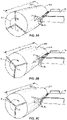
- Figures 3A-3C illustrate the sliders 30 of the work platform 19 adjusting to accommodate the complex contoured shape of the workpiece 200.
- the work platform 19 is positioned with the leading edges 31 of the sliders 30 positioned towards the workpiece 200.
- the leading edges 31 are positioned against the exterior surface 204 of the workpiece 200.
- the leading edges 31 are positioned in close proximity, such as within 2 inches of the exterior surface 204.
- Each of the sliders 30 is aligned at a different location along the length L of the workpiece 200.
- the movement of each slider 30 is a function of the sectional shape of the workpiece 200 at the location of the slider 30 and a rotational position of the workpiece 200.
- Figure 3A illustrates the workpiece 200 at a first rotational position.
- Each of the sliders 30 is adjusted with the leading edges 31 positioned at the workpiece 200.
- the workpiece 200 has rotated in the direction of arrow R about the center point C to a different second rotational position relative to the work platform 19.
- This different rotational position provides for a different point along the exterior surface 204 to be aligned with the sliders 30.
- one or more of the sliders 30 Due to the complex contoured shape of the workpiece 200, one or more of the sliders 30 has laterally moved towards or away from the workpiece 200 to match the sectional shape where the slider 30 is positioned along the length L.
- Each of the sliders 30 moves separately from the other sliders 30.
- the amount of movement of each slider 30 is a function of the shape of the workpiece 200 at the location of the slider 30 and the rotational position of the workpiece 200.
- One or more of the sliders 30 may not move when the sectional shape of the workpiece 200 is constant between the different rotational positions.
- Figure 3C illustrates the workpiece 200 at a third rotational position relative to the work platform 19. Again, one or more of the sliders 30 has laterally adjusted relative to the workpiece 200 to conform to the sectional shape where the slider 30 is located along the length L. In each of the different rotational positions, the leading edges 31 of the sliders 30 remain at the workpiece 200 to eliminate and/or reduce gaps.
- the work platform 19 can be used to locate workers at various positions relative to the workpiece 200.
- Figure 4 illustrates one example with a pair of work platforms 19a, 19b positioned on opposing sides of a workpiece 200.
- the work platforms 19 are elevated above the floor 201 and provide a structure to support one or more workers that are working on the workpiece 200.
- the work platforms 19 are positioned to allow the workers to access the workpiece 200 as the workpiece 200 is rotated about a centerline C.
- the work platform 19 can include various lengths. In one example, the workstation 19 has a length that matches the length L of the workpiece 200. Other examples include a length that is shorter than the workpiece 200, and a length that is longer than the workpiece 200.
- the work platform 19 can include various numbers of sliders 30. In one example, the sliders 30 extend across the entirety of the work platform 19. In another example, the sliders 30 are positioned along a limited length of the work platform 19.
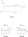
- Figure 5 illustrates a slider 30 that includes a leading edge 31 that is positioned towards the workpiece 200, an opposing trailing edge 32, and lateral sides 33, 34 that extend between the leading and trailing edges 31, 32.
- Figure 5 includes a slider 30 with a substantially rectangular shape. Sliders 30 can also include various other shapes and sizes. In one example, each of the sliders 30 of a work platform 19 include the same shape and size. In another example, one or more of the sliders 30 includes a different shape and/or size.
- Figure 5 further includes the leading edge 31 being flat and perpendicular to the lateral sides 33, 34. Other examples include the leading edge 31 having different shapes.
- the sliders 30 are positioned with one or both of the lateral sides 33, 34 contacting against adjacent sliders 30.
- This spacing forms a continuous floor 73 as illustrated in Figure 1 without spaces that could cause a trip hazard or provide for a tool to fall through to the floor 201 below.
- a space is positioned between one or both of the lateral sides 33, 34 and the adjacent sliders 30.
- the sliders 30 can be supported on the work platform 19 in a variety of different manners.
- Figure 6A illustrates the sliders 30 being mounted to a top side of a base 70.
- the sliders 30 form the floor 73 on which the workers stand.
- the movement of the sliders 30 as illustrated by arrow A can be relatively small and/or slow to still provide for the floor 73 to safely support the workers.
- Figure 6B includes an example in which a mat 72 is positioned on a top side of the sliders 30.
- the mat 72 can be attached to one or both of the sliders 30 and the base 70.
- the mat 72 can be formed from an elastic material, such as rubber to accommodate the moving sliders 30.
- the mat 72 forms the surface of the floor 73 and stretches during movement of the sliders 30 such that the workers do not feel the movement.
- the mats 72 have a rectangular shape and are connected at the corners to adjacent sliders 30.
- the mats 72 have a flexibility to accommodate the differences in movement between the sliders 30.
- adjacent sliders 30 can move a relative difference of about one inch during the lateral movement.
- Figure 7 illustrates a portion of a work platform 19 with sliders 30a, 30b, 30c positioned on a base 70.
- a slider is removed from the base 70 to illustrate rails 71 that are mounted to the base 70 and are configured to movably support the sliders 30 to provide for the lateral movement.
- Corresponding rails extend from the bottom of the sliders 30 and engage with the rails 71.
- a mat 72 extends over one or more of the sliders 30 and forms the floor 73.
- Figure 7 includes just a pair of mats 72 attached to the sliders 72, however, additional mats 72 would be attached across the sliders 30 to form a larger and complete floor 73 when the work platform 19 is completely constructed.
- the sliders 70 are positioned below the floor 73.
- the sliders 30 are positioned below the base 70 which forms the floor 73.
- the top surface of the sliders 30 extend the floor 73 outward from the base 70 towards the workpiece 200.
- the sliders 30 can be driven in a number of different manners to move laterally for the leading edges 31 to remain at the workpiece 200.
- Figure 9 illustrates one example that includes the sliders 30 connected to a camshaft 60 that is driven by a motor 40.
- the camshaft 60 is positioned in proximity to the sliders 30 and includes cams 62 spaced apart along the length.
- a link member 50 extends between each of the cams 62 and the corresponding slider 30.
- Each of the link members 50 follows a cam path on the corresponding cam 62 such that the movement of the slider 30 corresponds to the sectional shape of the workpiece 200 where the slider 30 is located.
- the cams 62 each include a cam path 61 that is followed by the link member 50.
- the cam path 61 can be positioned at various locations on the cam 60.
- Figure 10 illustrates a cam 62 having a complex shape with an irregular exterior edge 64.
- An opening 63 extends through the cam 62 to receive the camshaft 60.
- the cam path 61 is positioned inward from the exterior edge 64.
- Figure 11 includes a cam 62 with the cam path 61 formed at the exterior edge 64.
- the link member 50 operatively connects the slider 30 to the cam path 61.
- the link member 50 includes an elongated shape with a first end 51 attached to the cam path 61 and the second end 52 attached to the slider 30.
- the first end 51 includes a clevis 53 that extends on opposing sides of a cam 62 and rides within the cam path 61.
- the first end 51 rides in the cam path 61 that is recessed around the exterior edge of the cam 62.
- the second end 52 is attached to the slider 30 at the trailing edge 31.
- Other examples include an attachment at other points along the slider 30.
- the motor 40 is connected to and configured to rotate the camshaft 60 to provide for the movement of the sliders 30 to be synchronized with the workpiece 200.
- the motor 40 is in communication with a motor 42 that rotates the workpiece 200.
- the motors 40, 42 are electrically linked to provide for the synchronized movement of the workpiece 200 and the sliders 30.
- motor 42 is attached to a mandrel that extends through the workpiece 200.
- a single motor such as motor 40 or motor 42, is mechanically linked to and rotates both the camshaft 60 and the mandrel that extends through the workpiece 200.
- a control unit 80 provides for the synchronized movement.
- Figure 13 illustrates a control unit 80 configured to control one or more of the motors 40, 42.
- An interface 88 provides for communicatively connecting with the motors 40, 42.
- the control unit 80 includes a control circuit 81 and a memory circuit 82.
- the control circuit 81 controls the operation of the motors 40, 42 according to program instructions stored in the memory circuit 82.
- the control circuit 81 includes one or more circuits, microcontrollers, microprocessors, hardware, or a combination thereof.
- Memory circuit 82 includes a non-transitory computer readable storage medium storing program instructions, such as a computer program product, that configures the control circuit 81 to implement one or more of the techniques discussed herein.
- Memory circuit 82 can include various memory devices such as, for example, read-only memory, and flash memory. In one example, memory circuit 82 is a separate component as illustrated in Figure 13 . In another example, memory circuit 82 is incorporated with the control circuit 81. In one example, motion profiles for the sliders 30 are stored in the memory circuit 82 to control the movement of the sliders 30.
- a user interface 84 provides for a user to control one or more aspects of one or more of the motors 40, 42. This can include one or more displays 85 for displaying information to the user.
- the user interface 84 can also include one or more input devices 86 such as but not limited to a keypad, touchpad, roller ball, and joystick. The one or more input devices 86 provide for the user to enter commands to the control circuit 81.
- each of the motors 40, 42 is a stepper motor or a servo-controlled motor.
- the motors divide their rotational range into a series of equal steps.
- the control unit 80 can control their positions by signaling commands to move motors 40, 42 which provides for rotational movement in defined increments to the desired rotational positions. This incremental, stepped functionality provides for the control unit 80 to maintain the motors 40, 42 synchronized and the sliders 30 moving in accordance with the sectional shape of the nominal exterior surface 204 of the workpiece 200.
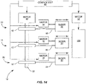
- Figure 14 illustrates another example of a work platform 19 that synchronizes the movement of the sliders 30.
- Motors 44 are attached to each of the sliders 30 to provide for the lateral movement to follow the workpiece 200.
- a camshaft 60 is driven by a motor 40 and operatively connected to each of the sliders 30 by a link member 50.
- the motors 44 are configured to provide the movement force, with the camshaft 60 and link members 50 attached to the sliders 30 to act as a redundant mechanical check of their synchronized movement with the workpiece 200.
- a control unit 80 oversees the operation and receives signals from and controls operations of the motors 40, 42, 44 to maintain the synchronized movement.
- Figure 15 illustrates an example in which the cams 62 are driven by separate motors 44.
- the cams 62 are operatively connected via link members 50 to the sliders 30 to control the lateral movement relative to the workpiece 200.
- a control unit 80 controls the operation of the motors 42, 44 to maintain the synchronized movement.
- the cams 62 and link members 50 eliminate and/or reduce the risk of the sliders 30 becoming misaligned with the rotation of the workpiece 200. This maintained alignment ensures that the gaps formed between the sliders 30 and the workpiece 200 remain within an acceptable size and the sliders 30 do not contact against the workpiece 200.
- Figure 16 illustrates an example in which motors 44 provide the force for moving the sliders 30 relative to the workpiece 200.
- a control unit 80 controls the operations of the motors 44 and operation of motor 42 that rotates the workpiece 200.
- the camshaft and link members have been removed from this example as the digital control of the motors 44 provides for the synchronization.
- motors 44 that drive the sliders 30 are used for large work platforms 19 that include a large number of sliders 30.
- the motors 44 can drive the sliders 30 and provide for more accurate movement than may be possible with a camshaft 60.
- a work platform 19 that uses slider motors 44 is about fifty feet long to extend along the length of a corresponding workpiece 200.
- the motor 42 that rotates the workpiece 200 also provides a driving force to move the sliders 30.
- the motor 42 is mechanically linked to the sliders 30, such as a chain drive, gear drive, or shaft drive. Because the motor 42 provides the force for both rotation of the workpiece 200 and movement of the sliders 30, the movement of these components is synchronized.
- Figure 17 illustrates a method of aligning a work platform 19 relative to a workpiece 200.
- the work platform 19 is positioned along a length of the workpiece 200 (block 300). This can include either moving the work platform 19 to the workpiece 200, moving the workpiece 200 to the work platform 19, or a combination of both. This includes positioning the leading edges 31 of sliders 30 at the workpiece 200.
- the work platform 19 includes a camshaft 60.
- the work platform 19 is positioned with a centerline of the camshaft 60 being parallel with a centerline of the workpiece 200.
- the sliders 30 have a centerline that is perpendicular to a centerline of the workpiece 200.
- the workpiece 200 is rotated while the work platform 19 is positioned at the workpiece 200 (block 302). This provides for the one or more workers on the work platform 19 to continue working on the workpiece without having to move off of the work platform 19 to adjust the position. This provides for a higher production rate as the work area is brought to the workers in a fast, orderly process.
- the method includes individually moving the sliders 30 towards and away from the workpiece 200 (block 304).
- the movement of each of the sliders 30 is a function of the sectional shape of the workpiece 200 at the slider 30 and a rotational position of the workpiece 200.
- the distance between the leading edges 31 and the workpiece 200 varies during rotation of the workpiece 200. In another example, the distance between the leading edges 31 and the workpiece 200 remains constant.
- the work platform 19 can be used for a variety of different workpieces 200.
- the work platform 19 is used for manufacturing composite aircraft components.
- Each component is constructed from overlapping composite sheets.
- the rotating workpiece 200 provides for the workers to apply the composite sheets around the entirety of the component to build the composite part.
- the work platform 19 is applicable for positioning workers to perform work on a variety of different workpieces 200.
- One application includes work on an aircraft sections that have relatively large sizes.
- the types of aircraft can vary, including various commercial aircraft, manned aircraft, unmanned aircraft, manned spacecraft, unmanned spacecraft, manned rotorcraft, unmanned rotorcraft, satellites, rockets, missiles, manned terrestrial aircraft, unmanned terrestrial aircraft, manned surface water borne aircraft, unmanned surface water borne aircraft, manned sub-surface water borne aircraft, unmanned sub-surface water borne aircraft, and combinations thereof.
- the present work platform 19 may be carried out in other ways than those specifically set forth herein without departing from the essential characteristics.
- the present embodiments are to be considered in all respects as illustrative and not restrictive, and all changes coming within the meaning and equivalency range of the appended claims are intended to be embraced therein.
Landscapes
- Engineering & Computer Science (AREA)
- Manufacturing & Machinery (AREA)
- Architecture (AREA)
- Mechanical Engineering (AREA)
- Transportation (AREA)
- Aviation & Aerospace Engineering (AREA)
- Civil Engineering (AREA)
- Structural Engineering (AREA)
- Automatic Assembly (AREA)
- Workshop Equipment, Work Benches, Supports, Or Storage Means (AREA)
- Attitude Control For Articles On Conveyors (AREA)
Abstract
Description
- The present disclosure relates generally to the field of work platforms and, more specifically, to work platforms that adjust to accommodate a rotating workpiece.
- Manufacturing facilities include platforms to position one or more workers in proximity to a workpiece. The platforms are large enough to hold one or more workers and the tools necessary to complete work on the workpiece. For large workpieces, the platforms are elevated above a floor. The platforms are designed to keep the workers safe while performing the work. This includes positioning the leading edge of the platform in proximity to the work piece. This prevents and/or reduces a gap between the platform and workpiece that could cause a worker to fall through to the floor, or to get their foot trapped which could lead to an injury. This also prevents tools and materials from inadvertently falling through the gap and down to the floor below.
- At some facilities, the workpieces are positioned on a mandrel that rotates the workpiece. This is particularly applicable for large workpieces. This allows for the workpiece to rotate past the worker who remains on the platform and can perform work on an entire workpiece. For example, aircraft tooling is often constructed from multiple different large sections. The individual sections are mounted on a mandrel and then rotated to allow a worker to complete work tasks on the entirety of the section without moving from the platform. In one specific example, a fuselage of a large aircraft is constructed from multiple pieces that are each constructed and then subsequently attached together.
- An issue with this type of platform is the workpiece may include a complex contoured shape with a varying nominal exterior surface. A work platform with a fixed shape is positioned at the workpiece to support the workers. Because of the shape of the workpiece, a gap is formed between the workpiece and the work platform at one or more rotational positions of the workpiece. The size of the gap can vary depending upon the complex contoured shape of the workpiece.
- One current work platform addresses this issue by the platform being constructed from two or more smaller sections. The sections are configured to be manually moved by the workers to position the leading edges at the workpiece at each of the various rotational positions. This requires the workers to move off of the platform, insert safety guards, move the sections of the platform away from the work piece, rotate the work piece while the sections are positioned away, manually move the sections back to the workpiece, and remove the safety guards. Once the platform sections are placed back at the workpiece, the workers can again move onto the platform and begin work. This is a time-consuming process for the workers to move and reposition the platform sections. Further, no work can be performed on the workpiece while the workers are moving the platform sections.
- Some current systems have included an automated work platform. Sensors are positioned to detect the size of the gap between the platform and the workpiece. However, the sensors can become dirty or otherwise blocked which prevent their operation. Further, these systems can have difficulty with detecting a size of the gap when irregular details of the workpiece such as small troughs and protrusions that can be positioned on the exterior of the workpiece. These irregular details can cause the sensors to improperly position the platform relative to the workpiece.
- One aspect is directed to a work platform configured to be positioned in proximity to a rotating workpiece. The work platform comprises sliders aligned along a length of the work platform with each of the sliders comprising a leading edge, a trailing edge, and opposing lateral edges. The sliders are arranged with the leading edges positioned towards the workpiece. One or more motors that move the sliders towards and away from the workpiece to maintain the leading edges at the workpiece. The position of the leading edges is a function of the sectional shape of the workpiece at the slider and the rotational position of the workpiece.
- In another aspect, the sliders are positioned together with at least one of the lateral edges sliding along a lateral edge of an adjacent one of the sliders.
- In another aspect, the platform comprises a base that supports the sliders, and rails mounted to the base and connected to the sliders with the rails engaged with the sliders for the sliders to move relative to the base.
- In another aspect, the platform comprises a camshaft that is rotated by the one or more motors, cam paths spaced apart along the camshaft with each of the cam paths corresponding to the sectional shape of the workpiece at the cam path, and link members connected to the cam paths and the sliders.
- In another aspect, the platform comprises a workpiece motor to rotate the workpiece, and a control unit configured to control the one or more motors and the workpiece motor to synchronize the movement of the sliders with the rotation of the workpiece.
- In another aspect, the control unit is configured to maintain the leading edges of the sliders at a constant distance away from the workpiece with the movement of each of the sliders controlled by one of the one or more motors according to a predefined motion profile.
- In another aspect, the platform comprises a mat connected to two or more of the sliders with the sliders being movable relative to the mat.
- In another aspect, two or more of the sliders move different amounts during rotation of the workpiece.
- One aspect is directed to a work platform configured to be positioned in proximity to a rotating workpiece. The work platform comprises a base and sliders supported by the base and that extend along the workpiece with the sliders located at a different position along the length of the workpiece. The sliders are movable relative to the base to adjust a distance of leading edges of the sliders relative to the workpiece. One or more motors move the sliders relative to the base. The movement of each of the sliders is a function of the sectional shape of the workpiece at the position of the slider along the length of the workpiece and a rotational position of the workpiece.
- In another aspect, the sliders comprise a leading edge that is positioned towards the workpiece and lateral edges with the sliders being aligned together with the lateral edges of adjacent ones of the sliders in proximity to form a continuous floor.
- In another aspect, two or more of the sliders move different amounts during rotation of the workpiece to maintain the leading edges of the sliders at the workpiece.
- In another aspect, the work platform comprises cams spaced apart and positioned at the sliders with the cams comprising a cam path that corresponds to the sectional shape of the workpiece where the cam is located along the length of the workpiece, and link members that extend between cams and the sliders.
- In another aspect, the work platform comprises a control unit configured to control the one or more motors to synchronize the movement of the sliders with the rotational position of the workpiece.
- In another aspect, the sliders form a floor of the work platform.
- In another aspect, the work platform comprises a mat that extends over and is connected to two or more of the sliders with the sliders being movable relative to the mat.
- One aspect is directed to a method of aligning a work platform relative to a workpiece. The method comprises: positioning the work platform along a length of the workpiece with leading edges of sliders on the work platform positioned at the workpiece; rotating the workpiece while the work platform is positioned along the workpiece; and individually moving the sliders towards and away from the workpiece with the movement of each of the sliders being a function of the sectional shape of the workpiece at the slider and a rotational position of the workpiece. In another aspect, the method further comprises maintaining the leading edge of the sliders at a constant distance away from the workpiece.
- In another aspect, the method further comprises operatively connecting each of the sliders to a cam that comprises a cam path that corresponds to the sectional shape of the workpiece at the cam; and rotating each of the cams in a synchronized manner with the workpiece and laterally moving the sliders.
- In another aspect, the method further comprises moving two or more the sliders different amounts while rotating the workpiece between a first rotational position and a second rotational position.
- In another aspect, the method further comprises moving one or more of the sliders and concurrently maintaining a position of one or more of the sliders.
- The features, functions and advantages that have been discussed can be achieved independently in various aspects or may be combined in yet other aspects, further details of which can be seen with reference to the following description and the drawings.
-
-
Figure 1 is a schematic top view of a work platform with sliders that are aligned along the length of a workpiece. -
Figure 2 is a schematic side view of a work platform positioned at a workpiece with a complex contoured shape. -
Figures 3A, 3B, and 3C illustrate a work platform positioned at a workpiece at three different rotational positions of the workpiece. -
Figure 4 is a perspective view of a pair of work platforms positioned along a workpiece. -
Figure 5 is a schematic top view of a slider. -
Figure 6A is a schematic side view of a slider supported by a base. -
Figure 6B is a schematic side view of a slider supported by a base a with a mat positioned on the slider. -
Figure 7 is a perspective view of a partially-constructed work platform with three sliders mounted to a base and configured to be driven by a camshaft. -
Figure 8 is a schematic side view of a slider supported by a base. -
Figure 9 is a top schematic view of a work platform positioned at a workpiece. -
Figure 10 is a side view of a cam. -
Figure 11 is a side view of a cam. -
Figure 12 is a top schematic view of a work platform positioned at a workpiece. -
Figure 13 is a schematic diagram of a control unit. -
Figure 14 is a top schematic view of a work platform positioned at a workpiece. -
Figure 15 is a top schematic view of a work platform positioned at a workpiece. -
Figure 16 is a top schematic view of a work platform positioned at a workpiece. -
Figure 17 is a flowchart diagram of a method of aligning awork platform 19 relative to a workpiece. - The present application is directed to a
work platform 19 as illustrated inFigure 1 configured to support one or more workers in proximity to aworkpiece 200. Thework platform 19 includessliders 30 that are aligned along the length L of theworkpiece 200. Thesliders 30 are movable towards and away from theworkpiece 200 as illustrated in arrow A to maintain theleading edges 31 at theworkpiece 200 to minimize and/or eliminate gaps. Thesliders 30 are individually movable with a position of each of thesliders 30 being a function of the sectional shape of theworkpiece 200 where theslider 30 is positioned and the rotational position of theworkpiece 200. - The
work platform 19 provides for theleading edge 31 of thesliders 30 to remain at theworkpiece 200 during rotation of theworkpiece 200. Theworkpiece 200 has a complex contoured shape along the length L. As illustrated inFigure 2 , this complex sectional shape has a non-constant cross section with a variable radius R measured between the centerline C and the nominalexterior surface 204. The lateral movement of thesliders 30 adjusts the position of theleading edges 31 relative to theworkpiece 200 to prevent and/or reduce the size of a gap formed between thework platform 19 andworkpiece 200. This reduction or elimination in the gap provides for a safe work environment for workers on thework platform 19. -
Figures 3A-3C illustrate thesliders 30 of thework platform 19 adjusting to accommodate the complex contoured shape of theworkpiece 200. Thework platform 19 is positioned with the leadingedges 31 of thesliders 30 positioned towards theworkpiece 200. In one example, the leadingedges 31 are positioned against theexterior surface 204 of theworkpiece 200. In another example, the leadingedges 31 are positioned in close proximity, such as within 2 inches of theexterior surface 204. - Each of the
sliders 30 is aligned at a different location along the length L of theworkpiece 200. The movement of eachslider 30 is a function of the sectional shape of theworkpiece 200 at the location of theslider 30 and a rotational position of theworkpiece 200.Figure 3A illustrates theworkpiece 200 at a first rotational position. Each of thesliders 30 is adjusted with the leadingedges 31 positioned at theworkpiece 200. - As illustrated in
Figure 3B , theworkpiece 200 has rotated in the direction of arrow R about the center point C to a different second rotational position relative to thework platform 19. This different rotational position provides for a different point along theexterior surface 204 to be aligned with thesliders 30. Due to the complex contoured shape of theworkpiece 200, one or more of thesliders 30 has laterally moved towards or away from theworkpiece 200 to match the sectional shape where theslider 30 is positioned along the length L. Each of thesliders 30 moves separately from theother sliders 30. Thus, the amount of movement of eachslider 30 is a function of the shape of theworkpiece 200 at the location of theslider 30 and the rotational position of theworkpiece 200. One or more of thesliders 30 may not move when the sectional shape of theworkpiece 200 is constant between the different rotational positions. -
Figure 3C illustrates theworkpiece 200 at a third rotational position relative to thework platform 19. Again, one or more of thesliders 30 has laterally adjusted relative to theworkpiece 200 to conform to the sectional shape where theslider 30 is located along the length L. In each of the different rotational positions, the leadingedges 31 of thesliders 30 remain at theworkpiece 200 to eliminate and/or reduce gaps. - The
work platform 19 can be used to locate workers at various positions relative to theworkpiece 200.Figure 4 illustrates one example with a pair ofwork platforms workpiece 200. Thework platforms 19 are elevated above thefloor 201 and provide a structure to support one or more workers that are working on theworkpiece 200. Thework platforms 19 are positioned to allow the workers to access theworkpiece 200 as theworkpiece 200 is rotated about a centerline C. - The
work platform 19 can include various lengths. In one example, theworkstation 19 has a length that matches the length L of theworkpiece 200. Other examples include a length that is shorter than theworkpiece 200, and a length that is longer than theworkpiece 200. Thework platform 19 can include various numbers ofsliders 30. In one example, thesliders 30 extend across the entirety of thework platform 19. In another example, thesliders 30 are positioned along a limited length of thework platform 19. -
Figure 5 illustrates aslider 30 that includes aleading edge 31 that is positioned towards theworkpiece 200, an opposing trailingedge 32, andlateral sides edges Figure 5 includes aslider 30 with a substantially rectangular shape.Sliders 30 can also include various other shapes and sizes. In one example, each of thesliders 30 of awork platform 19 include the same shape and size. In another example, one or more of thesliders 30 includes a different shape and/or size.Figure 5 further includes the leadingedge 31 being flat and perpendicular to the lateral sides 33, 34. Other examples include the leadingedge 31 having different shapes. - In one example as illustrated in
Figure 1 , thesliders 30 are positioned with one or both of the lateral sides 33, 34 contacting againstadjacent sliders 30. This spacing forms acontinuous floor 73 as illustrated inFigure 1 without spaces that could cause a trip hazard or provide for a tool to fall through to thefloor 201 below. In another example, a space is positioned between one or both of the lateral sides 33, 34 and theadjacent sliders 30. - The
sliders 30 can be supported on thework platform 19 in a variety of different manners. -
Figure 6A illustrates thesliders 30 being mounted to a top side of abase 70. In this example, thesliders 30 form thefloor 73 on which the workers stand. To ensure the safety of the workers, the movement of thesliders 30 as illustrated by arrow A can be relatively small and/or slow to still provide for thefloor 73 to safely support the workers.Figure 6B includes an example in which amat 72 is positioned on a top side of thesliders 30. Themat 72 can be attached to one or both of thesliders 30 and thebase 70. Themat 72 can be formed from an elastic material, such as rubber to accommodate the movingsliders 30. Themat 72 forms the surface of thefloor 73 and stretches during movement of thesliders 30 such that the workers do not feel the movement. In one example, themats 72 have a rectangular shape and are connected at the corners toadjacent sliders 30. Themats 72 have a flexibility to accommodate the differences in movement between thesliders 30. In one specific example,adjacent sliders 30 can move a relative difference of about one inch during the lateral movement. -
Figure 7 illustrates a portion of awork platform 19 withsliders base 70. A slider is removed from the base 70 to illustraterails 71 that are mounted to thebase 70 and are configured to movably support thesliders 30 to provide for the lateral movement. Corresponding rails extend from the bottom of thesliders 30 and engage with therails 71. Amat 72 extends over one or more of thesliders 30 and forms thefloor 73.Figure 7 includes just a pair ofmats 72 attached to thesliders 72, however,additional mats 72 would be attached across thesliders 30 to form a larger andcomplete floor 73 when thework platform 19 is completely constructed. - In another example as illustrated in
Figure 8 , thesliders 70 are positioned below thefloor 73. In this example, thesliders 30 are positioned below thebase 70 which forms thefloor 73. The top surface of thesliders 30 extend thefloor 73 outward from the base 70 towards theworkpiece 200. - The
sliders 30 can be driven in a number of different manners to move laterally for theleading edges 31 to remain at theworkpiece 200.Figure 9 illustrates one example that includes thesliders 30 connected to acamshaft 60 that is driven by amotor 40. Thecamshaft 60 is positioned in proximity to thesliders 30 and includescams 62 spaced apart along the length. Alink member 50 extends between each of thecams 62 and the correspondingslider 30. Each of thelink members 50 follows a cam path on the correspondingcam 62 such that the movement of theslider 30 corresponds to the sectional shape of theworkpiece 200 where theslider 30 is located. - The
cams 62 each include acam path 61 that is followed by thelink member 50. Thecam path 61 can be positioned at various locations on thecam 60.Figure 10 illustrates acam 62 having a complex shape with anirregular exterior edge 64. Anopening 63 extends through thecam 62 to receive thecamshaft 60. In this example, thecam path 61 is positioned inward from theexterior edge 64.Figure 11 includes acam 62 with thecam path 61 formed at theexterior edge 64. - The
link member 50 operatively connects theslider 30 to thecam path 61. Thelink member 50 includes an elongated shape with afirst end 51 attached to thecam path 61 and thesecond end 52 attached to theslider 30. In one example as illustrated inFigure 7 , thefirst end 51 includes aclevis 53 that extends on opposing sides of acam 62 and rides within thecam path 61. In another example, thefirst end 51 rides in thecam path 61 that is recessed around the exterior edge of thecam 62. In another example, thesecond end 52 is attached to theslider 30 at the trailingedge 31. Other examples include an attachment at other points along theslider 30. - The
motor 40 is connected to and configured to rotate thecamshaft 60 to provide for the movement of thesliders 30 to be synchronized with theworkpiece 200. In one example as illustrated inFigure 12 , themotor 40 is in communication with amotor 42 that rotates theworkpiece 200. Themotors workpiece 200 and thesliders 30. In one example,motor 42 is attached to a mandrel that extends through theworkpiece 200. In another example, a single motor, such asmotor 40 ormotor 42, is mechanically linked to and rotates both thecamshaft 60 and the mandrel that extends through theworkpiece 200. - In one example, a
control unit 80 provides for the synchronized movement.Figure 13 illustrates acontrol unit 80 configured to control one or more of themotors interface 88 provides for communicatively connecting with themotors control unit 80 includes acontrol circuit 81 and amemory circuit 82. Thecontrol circuit 81 controls the operation of themotors memory circuit 82. Within examples, thecontrol circuit 81 includes one or more circuits, microcontrollers, microprocessors, hardware, or a combination thereof.Memory circuit 82 includes a non-transitory computer readable storage medium storing program instructions, such as a computer program product, that configures thecontrol circuit 81 to implement one or more of the techniques discussed herein.Memory circuit 82 can include various memory devices such as, for example, read-only memory, and flash memory. In one example,memory circuit 82 is a separate component as illustrated inFigure 13 . In another example,memory circuit 82 is incorporated with thecontrol circuit 81. In one example, motion profiles for thesliders 30 are stored in thememory circuit 82 to control the movement of thesliders 30. - A
user interface 84 provides for a user to control one or more aspects of one or more of themotors more displays 85 for displaying information to the user. Theuser interface 84 can also include one ormore input devices 86 such as but not limited to a keypad, touchpad, roller ball, and joystick. The one ormore input devices 86 provide for the user to enter commands to thecontrol circuit 81. - In one example, each of the
motors control unit 80 can control their positions by signaling commands to movemotors control unit 80 to maintain themotors sliders 30 moving in accordance with the sectional shape of the nominalexterior surface 204 of theworkpiece 200. -
Figure 14 illustrates another example of awork platform 19 that synchronizes the movement of thesliders 30.Motors 44 are attached to each of thesliders 30 to provide for the lateral movement to follow theworkpiece 200. Acamshaft 60 is driven by amotor 40 and operatively connected to each of thesliders 30 by alink member 50. In this example, themotors 44 are configured to provide the movement force, with thecamshaft 60 andlink members 50 attached to thesliders 30 to act as a redundant mechanical check of their synchronized movement with theworkpiece 200. Acontrol unit 80 oversees the operation and receives signals from and controls operations of themotors -
Figure 15 illustrates an example in which thecams 62 are driven byseparate motors 44. Thecams 62 are operatively connected vialink members 50 to thesliders 30 to control the lateral movement relative to theworkpiece 200. Acontrol unit 80 controls the operation of themotors - In one example of a
work platform 19 with acamshaft 60, thecams 62 andlink members 50 eliminate and/or reduce the risk of thesliders 30 becoming misaligned with the rotation of theworkpiece 200. This maintained alignment ensures that the gaps formed between thesliders 30 and theworkpiece 200 remain within an acceptable size and thesliders 30 do not contact against theworkpiece 200. -
Figure 16 illustrates an example in whichmotors 44 provide the force for moving thesliders 30 relative to theworkpiece 200. Acontrol unit 80 controls the operations of themotors 44 and operation ofmotor 42 that rotates theworkpiece 200. The camshaft and link members have been removed from this example as the digital control of themotors 44 provides for the synchronization. - In one example,
motors 44 that drive thesliders 30 are used forlarge work platforms 19 that include a large number ofsliders 30. Themotors 44 can drive thesliders 30 and provide for more accurate movement than may be possible with acamshaft 60. In one example, awork platform 19 that usesslider motors 44 is about fifty feet long to extend along the length of acorresponding workpiece 200. - In another example, the
motor 42 that rotates theworkpiece 200 also provides a driving force to move thesliders 30. Themotor 42 is mechanically linked to thesliders 30, such as a chain drive, gear drive, or shaft drive. Because themotor 42 provides the force for both rotation of theworkpiece 200 and movement of thesliders 30, the movement of these components is synchronized. -
Figure 17 illustrates a method of aligning awork platform 19 relative to aworkpiece 200. Thework platform 19 is positioned along a length of the workpiece 200 (block 300). This can include either moving thework platform 19 to theworkpiece 200, moving theworkpiece 200 to thework platform 19, or a combination of both. This includes positioning theleading edges 31 ofsliders 30 at theworkpiece 200. In one example, thework platform 19 includes acamshaft 60. Thework platform 19 is positioned with a centerline of thecamshaft 60 being parallel with a centerline of theworkpiece 200. In one example, thesliders 30 have a centerline that is perpendicular to a centerline of theworkpiece 200. - The
workpiece 200 is rotated while thework platform 19 is positioned at the workpiece 200 (block 302). This provides for the one or more workers on thework platform 19 to continue working on the workpiece without having to move off of thework platform 19 to adjust the position. This provides for a higher production rate as the work area is brought to the workers in a fast, orderly process. - During the rotation, the method includes individually moving the
sliders 30 towards and away from the workpiece 200 (block 304). The movement of each of thesliders 30 is a function of the sectional shape of theworkpiece 200 at theslider 30 and a rotational position of theworkpiece 200. - In one example, the distance between the
leading edges 31 and theworkpiece 200 varies during rotation of theworkpiece 200. In another example, the distance between theleading edges 31 and theworkpiece 200 remains constant. - The
work platform 19 can be used for a variety ofdifferent workpieces 200. In one example, thework platform 19 is used for manufacturing composite aircraft components. Each component is constructed from overlapping composite sheets. Therotating workpiece 200 provides for the workers to apply the composite sheets around the entirety of the component to build the composite part. - The
work platform 19 is applicable for positioning workers to perform work on a variety ofdifferent workpieces 200. One application includes work on an aircraft sections that have relatively large sizes. The types of aircraft can vary, including various commercial aircraft, manned aircraft, unmanned aircraft, manned spacecraft, unmanned spacecraft, manned rotorcraft, unmanned rotorcraft, satellites, rockets, missiles, manned terrestrial aircraft, unmanned terrestrial aircraft, manned surface water borne aircraft, unmanned surface water borne aircraft, manned sub-surface water borne aircraft, unmanned sub-surface water borne aircraft, and combinations thereof. - By the term "about" or "substantial" and "substantially" or "approximately," with reference to amounts or measurement values, it is meant that the recited characteristic, parameter, or value need not be achieved exactly. Rather, deviations or variations, including, for example, tolerances, measurement error, measurement accuracy limitations, and other factors known to those skilled in the art, may occur in amounts that do not preclude the effect that the characteristic was intended to provide.
- The
present work platform 19 may be carried out in other ways than those specifically set forth herein without departing from the essential characteristics. The present embodiments are to be considered in all respects as illustrative and not restrictive, and all changes coming within the meaning and equivalency range of the appended claims are intended to be embraced therein. - The disclosure also comprises examples according to the following numbered clauses:
- 1. A work platform configured to be positioned in proximity to a rotating workpiece, the work platform comprising:
- sliders aligned along a length of the work platform, the sliders comprising a leading edge, a trailing edge, and opposing lateral edges, the sliders are arranged with the leading edges positioned towards the workpiece; and
- one or more motors that move the sliders towards and away from the workpiece to maintain the leading edges at the workpiece and with a position of the leading edges being a function of the sectional shape of the workpiece at the slider and the rotational position of the workpiece.
- 2. The work platform of clause 1, wherein the sliders are positioned together with at least one of the lateral edges sliding along a lateral edge of an adjacent one of the sliders.
- 3. The work platform of any preceding clause, further comprising:
- a base that supports the sliders; and
- rails mounted to the base and connected to the sliders, the rails engage with the sliders for the sliders to move relative to the base.
- 4. The work platform of any preceding clause, further comprising:
- a camshaft that is rotated by the one or more motors;
- cam paths spaced apart along the camshaft with each of the cam paths corresponding to the sectional shape of the workpiece at the cam path; and
- link members connected to the cam paths and the sliders.
- 5. The work platform of any preceding clause, further comprising:
- a workpiece motor to rotate the workpiece; and
- a control unit configured to control the one or more motors and the workpiece motor to synchronize the movement of the sliders with rotation of the workpiece.
- 6. The work platform of any preceding clause, wherein the control unit is configured to maintain the leading edges of the sliders at a constant distance away from the workpiece with the movement of each of the sliders controlled by one of the one or more motors according to a predefined motion profile.
- 7. The work platform of any preceding clause, further comprising a mat connected to two or more of the sliders with the sliders being movable relative to the mat.
- 8. The work platform of any preceding clause, wherein two or more of the sliders move different amounts during rotation of the workpiece.
- 9. A work platform configured to be positioned in proximity to a rotating workpiece, the work platform comprising:
- a base;
- sliders supported by the base and that extend along the workpiece with the sliders located at a different position along the length of the workpiece, the sliders being movable relative to the base to adjust a distance of leading edges of the sliders relative to the workpiece;
- one or more motors to move the sliders relative to the base; and
- the movement of each of the sliders being a function of the sectional shape of the workpiece at the position of the slider along the length of the workpiece and a rotational position of the workpiece.
- 10. The work platform of any preceding clause, wherein the sliders comprise a leading edge that is positioned towards the workpiece and lateral edges, the sliders being aligned together with the lateral edges of adjacent ones of the sliders in proximity to form a continuous floor.
- 11. The work platform of any preceding clause, wherein two or more of the sliders move different amounts during rotation of the workpiece to maintain the leading edges of the sliders at the workpiece.
- 12. The work platform of any preceding clause, further comprising:
- cams spaced apart and positioned at the sliders, the cams comprising a cam path that corresponds to the sectional shape of the workpiece where the cam is located along the length of the workpiece; and
- link members that extend between cams and the sliders.
- 13. The work platform of any preceding clause, further comprising a control unit configured to control the one or more motors to synchronize the movement of the sliders with the rotational position of the workpiece.
- 14. The work platform of any preceding clause, wherein the sliders form a floor of the work platform.
- 15. The work platform of any preceding clause, further comprising a mat that extends over and is connected to two or more of the sliders with the sliders being movable relative to the mat.
- 16. A method of aligning a work platform relative to a workpiece, the method comprising:
- positioning the work platform along a length of the workpiece with leading edges of sliders on the work platform positioned at the workpiece;
- rotating the workpiece while the work platform is positioned along the workpiece; and
- individually moving the sliders towards and away from the workpiece with the movement of each of the sliders being a function of the sectional shape of the workpiece at the slider and a rotational position of the workpiece.
- 17. The method of clause 16, further comprising maintaining the leading edge of the sliders at a constant distance away from the workpiece.
- 18. The method of clause 16 and/or clause 17, further comprising:
- operatively connecting each of the sliders to a cam that comprises a cam path that corresponds to the sectional shape of the workpiece at the cam; and
- rotating each of the cams in a synchronized manner with the workpiece and laterally moving the sliders.
- 19. The method of any of clauses 16 to 18, further comprising moving two or more the sliders different amounts while rotating the workpiece between a first rotational position and a second rotational position.
- 20. The method of any of clauses 16 to 19, further comprising moving one or more of the sliders and concurrently maintaining a position of one or more of the sliders.
Claims (15)
- A work platform (19) configured to be positioned in proximity to a rotating workpiece (200), the work platform (19) comprising:sliders (30) aligned along a length of the work platform (19), the sliders (30) comprising a leading edge (31), a trailing edge (32), and opposing lateral edges (33, 34), the sliders (30) are arranged with the leading edges (31) positioned towards the workpiece (200); andone or more motors (40, 44) that move the sliders (30) towards and away from the workpiece (200) to maintain the leading edges (31) at the workpiece (200) and with a position of the leading edges (31) being a function of the sectional shape of the workpiece (200) at the slider (30) and the rotational position of the workpiece (200).
- The work platform of claim 1, wherein the sliders (30) are positioned together with at least one of the lateral edges (33, 34) sliding along a lateral edge (33, 34) of an adjacent one of the sliders (30).
- The work platform of claim 1 or claim 2, further comprising:a base (70) that supports the sliders (30); andrails (71) mounted to the base (70) and connected to the sliders (30), the rails (71) engage with the sliders (30) for the sliders (30) to move relative to the base (70).
- The work platform according to any preceding claim, further comprising:a camshaft (60) that is rotated by the one or more motors (40);cam paths (61) spaced apart along the camshaft (60) with each of the cam paths (61) corresponding to the sectional shape of the workpiece (200) at the cam path (61); andlink members (50) connected to the cam paths (61) and the sliders (30).
- The work platform according to any preceding claim, further comprising:a workpiece motor (42) to rotate the workpiece (200); anda control unit (80) configured to control the one or more motors (40, 44) and the workpiece motor (42) to synchronize the movement of the sliders (30) with rotation of the workpiece (200).
- The work platform of claim 5, wherein the control unit (80) is configured to maintain the leading edges (31) of the sliders (30) at a constant distance away from the workpiece (200) with the movement of each of the sliders (30) controlled by one of the one or more motors (40) according to a predefined motion profile.
- The work platform (19) according to any preceding claim, further comprising a mat (72) connected to two or more of the sliders (30) with the sliders (30) being movable relative to the mat (72).
- The work platform (19) according to any preceding claim, wherein two or more of the sliders (30) move different amounts during rotation of the workpiece (200).
- The work platform (19) according to any preceding claim, further comprising a base (70), wherein the sliders are supported by the base and are moveable relative to the base.
- The work platform (19) of claim 9, wherein the one or motors are arranged to move the sliders relative to the base.
- A method of aligning a work platform (19) relative to a workpiece (200), the method comprising:positioning the work platform (19) along a length of the workpiece (200) with leading edges (31) of sliders (30) on the work platform (19) positioned at the workpiece (200);rotating the workpiece (200) while the work platform (19) is positioned along the workpiece (200); andindividually moving the sliders (30) towards and away from the workpiece (200) with the movement of each of the sliders (30) being a function of the sectional shape of the workpiece (200) at the slider (30) and a rotational position of the workpiece (200).
- The method of claim 11, further comprising maintaining the leading edge (31) of the sliders (30) at a constant distance away from the workpiece (200).
- The method of claim 11 or 12, further comprising:operatively connecting each of the sliders (30) to a cam (62) that comprises a cam path (61) that corresponds to the sectional shape of the workpiece (200) at the cam (62); androtating each of the cams (62) in a synchronized manner with the workpiece (200) and laterally moving the sliders (30).
- The method according to any of claims 11 to 13, further comprising moving two or more the sliders (30) different amounts while rotating the workpiece (200) between a first rotational position and a second rotational position.
- The method according to any of claims 11 to 14, further comprising moving one or more of the sliders (30) and concurrently maintaining a position of one or more of the sliders (30).
Applications Claiming Priority (1)
| Application Number | Priority Date | Filing Date | Title |
|---|---|---|---|
| US17/372,858 US12434858B2 (en) | 2021-07-12 | 2021-07-12 | Work platforms and methods of use |
Publications (2)
| Publication Number | Publication Date |
|---|---|
| EP4119447A1 true EP4119447A1 (en) | 2023-01-18 |
| EP4119447B1 EP4119447B1 (en) | 2024-10-09 |
Family
ID=81346423
Family Applications (1)
| Application Number | Title | Priority Date | Filing Date |
|---|---|---|---|
| EP22166088.9A Active EP4119447B1 (en) | 2021-07-12 | 2022-03-31 | Work platforms and methods of use |
Country Status (7)
| Country | Link |
|---|---|
| US (1) | US12434858B2 (en) |
| EP (1) | EP4119447B1 (en) |
| JP (1) | JP2023011523A (en) |
| CN (1) | CN115593866A (en) |
| AU (1) | AU2022201842A1 (en) |
| BR (1) | BR102022004714A2 (en) |
| CA (1) | CA3153732C (en) |
Cited By (1)
| Publication number | Priority date | Publication date | Assignee | Title |
|---|---|---|---|---|
| EP4129831B1 (en) * | 2021-08-06 | 2025-01-22 | The Boeing Company | System and method to adjust extension lengths of slats of a work platform relative to a workpiece |
Families Citing this family (1)
| Publication number | Priority date | Publication date | Assignee | Title |
|---|---|---|---|---|
| CN116654281B (en) * | 2023-06-01 | 2025-10-21 | 西安电子科技大学 | A comprehensive debugging device and method for a cross-medium multi-rotor cross-medium aircraft |
Citations (4)
| Publication number | Priority date | Publication date | Assignee | Title |
|---|---|---|---|---|
| JP2008050111A (en) * | 2006-08-24 | 2008-03-06 | Hitachi Building Systems Co Ltd | Level difference elimination device |
| US20120036700A1 (en) * | 2009-04-30 | 2012-02-16 | Jae Eop Mun | Universal platform and aircraft assembly method using the same |
| US20120066907A1 (en) * | 2009-05-27 | 2012-03-22 | Airbus Operations (S.A.S.) | Installation for making a fuselage portion of an aircraft |
| US20160009155A1 (en) * | 2014-07-09 | 2016-01-14 | The Boeing Company | Wheel Mounting System |
Family Cites Families (21)
| Publication number | Priority date | Publication date | Assignee | Title |
|---|---|---|---|---|
| JPH0628400Y2 (en) * | 1988-02-10 | 1994-08-03 | 川崎重工業株式会社 | Aircraft wing engine maintenance device |
| JP2002087797A (en) | 2000-09-19 | 2002-03-27 | Komatsu Ltd | Drive control device for aerial work vehicles |
| SE524382C2 (en) | 2002-06-24 | 2004-08-03 | Maxmove Ab | Transport device with slave control |
| US7194358B2 (en) | 2004-02-25 | 2007-03-20 | The Boeing Company | Lift collision avoidance system |
| US8622170B2 (en) | 2004-02-26 | 2014-01-07 | Jlg Industries, Inc. | Lift vehicle with multiple capacity envelope control system and method |
| US7527222B2 (en) * | 2004-04-06 | 2009-05-05 | The Boeing Company | Composite barrel sections for aircraft fuselages and other structures, and methods and systems for manufacturing such barrel sections |
| DE102005003514A1 (en) * | 2005-01-25 | 2006-08-03 | Lufthansa Engineering And Operational Services Gmbh | Saddle platform for aircraft fuselage maintenance has frame supporting platform and with peripheral straps to engage fuselage |
| US8266778B2 (en) * | 2007-04-18 | 2012-09-18 | Airbus Deutschland Gmbh | Assembly apparatus for the assembly of a fuselage section |
| US8292265B2 (en) | 2009-07-17 | 2012-10-23 | Benzing James T | Mobile support apparatus |
| JP2013052948A (en) | 2011-09-02 | 2013-03-21 | West Nippon Expressway Co Ltd | Safety device for vehicle for high lift work |
| CN102701122B (en) | 2012-06-06 | 2015-03-11 | 中联重科股份有限公司 | A high-altitude vehicle operation stop control method, device, system and a high-altitude vehicle |
| KR20160000931U (en) | 2014-09-12 | 2016-03-22 | 대우조선해양 주식회사 | Apparatus for position compensation of lift car bascket |
| JP6741423B2 (en) * | 2015-12-25 | 2020-08-19 | 川崎重工業株式会社 | Aircraft dock equipment |
| US10167181B2 (en) | 2016-07-22 | 2019-01-01 | Chejiang Dingli Machinery Co., Ltd. | Hydraulic steering shear-fork type aerial work platform |
| US10625427B2 (en) | 2017-06-14 | 2020-04-21 | The Boeing Company | Method for controlling location of end effector of robot using location alignment feedback |
| US10005652B1 (en) | 2017-11-01 | 2018-06-26 | Kan Cui | Elevating lift with a stabilized movable base |
| US10829354B2 (en) | 2017-12-20 | 2020-11-10 | Cti Systems S.a.r.l. | Collision avoidance assistance system for movable work platforms |
| US11401051B2 (en) | 2018-02-19 | 2022-08-02 | The Boeing Company | Aircraft inspection systems and methods |
| US11238675B2 (en) | 2018-04-04 | 2022-02-01 | The Boeing Company | Mobile visual-inspection system |
| US11066838B2 (en) | 2018-07-12 | 2021-07-20 | The Boeing Company | Work platform mover system |
| US11718426B1 (en) * | 2020-05-29 | 2023-08-08 | United Launch Alliance, L.L.C. | Highly adaptable platform |
-
2021
- 2021-07-12 US US17/372,858 patent/US12434858B2/en active Active
-
2022
- 2022-03-14 BR BR102022004714-6A patent/BR102022004714A2/en unknown
- 2022-03-16 AU AU2022201842A patent/AU2022201842A1/en active Pending
- 2022-03-23 CA CA3153732A patent/CA3153732C/en active Active
- 2022-03-31 EP EP22166088.9A patent/EP4119447B1/en active Active
- 2022-04-28 CN CN202210457436.8A patent/CN115593866A/en active Pending
- 2022-07-08 JP JP2022110287A patent/JP2023011523A/en active Pending
Patent Citations (4)
| Publication number | Priority date | Publication date | Assignee | Title |
|---|---|---|---|---|
| JP2008050111A (en) * | 2006-08-24 | 2008-03-06 | Hitachi Building Systems Co Ltd | Level difference elimination device |
| US20120036700A1 (en) * | 2009-04-30 | 2012-02-16 | Jae Eop Mun | Universal platform and aircraft assembly method using the same |
| US20120066907A1 (en) * | 2009-05-27 | 2012-03-22 | Airbus Operations (S.A.S.) | Installation for making a fuselage portion of an aircraft |
| US20160009155A1 (en) * | 2014-07-09 | 2016-01-14 | The Boeing Company | Wheel Mounting System |
Cited By (1)
| Publication number | Priority date | Publication date | Assignee | Title |
|---|---|---|---|---|
| EP4129831B1 (en) * | 2021-08-06 | 2025-01-22 | The Boeing Company | System and method to adjust extension lengths of slats of a work platform relative to a workpiece |
Also Published As
| Publication number | Publication date |
|---|---|
| US12434858B2 (en) | 2025-10-07 |
| CA3153732A1 (en) | 2023-01-12 |
| CN115593866A (en) | 2023-01-13 |
| AU2022201842A1 (en) | 2023-02-02 |
| CA3153732C (en) | 2025-08-05 |
| EP4119447B1 (en) | 2024-10-09 |
| US20230010488A1 (en) | 2023-01-12 |
| BR102022004714A2 (en) | 2023-01-17 |
| JP2023011523A (en) | 2023-01-24 |
Similar Documents
| Publication | Publication Date | Title |
|---|---|---|
| US12434858B2 (en) | Work platforms and methods of use | |
| US6557689B2 (en) | Assembly for supporting and retaining glass sheets | |
| EP2692668B1 (en) | Apparatus and method for palletizing multi-reference loads | |
| US9073162B2 (en) | Method and apparatus for cutting a mill plate | |
| JP6516768B2 (en) | Method and apparatus for making blanks of dough pieces from one or more dough sheets | |
| US20020060386A1 (en) | Device for clamping and holding an elongated workpiece | |
| WO2021218257A1 (en) | Machining method of automatic edge banding machine | |
| CN108672777B (en) | Automatic machining equipment for wire stripping blade and cutting and milling angle control method thereof | |
| EP3846630A1 (en) | Arrangement and method for conveying poultry | |
| US20170291296A1 (en) | High precision work piece processing system | |
| WO2007010066A2 (en) | Flexible assembly for performing work on large surfaces | |
| US20030015001A1 (en) | Method of setting a machine for machining a sheet of glass, and machine configurable thereby | |
| EP2070647A1 (en) | Modular production line | |
| IT9003677A1 (en) | PROCESS FOR AUTOMATIC POLISHED WIRE PROCESSING OF THE EDGE OF GLASS SLABS OF ANY SHAPE AND MACHINE FOR THE EXECUTION OF SUCH PROCEDURE. | |
| CH629404A5 (en) | METHOD FOR POSITIONING PLATE-SHAPED WORKPIECES WITH REGARD TO A MACHINING POINT AND DEVICE FOR IMPLEMENTING THE METHOD. | |
| EP4257317A1 (en) | Numerical-control work centre for machining plates of glass or plates of natural or synthetic stone material with machining head having an auxiliary plate-supporting unit, and machining method | |
| US20240429431A1 (en) | Battery grid feeder for a pasting machine | |
| US7351019B2 (en) | Clamping mechanism for an elongated workpiece | |
| EP0848681B1 (en) | Improved gate change facility | |
| CN110509363A (en) | The feeding positioning mechanism of carving and milling machine | |
| CN211891249U (en) | Engraving and milling machine | |
| KR101185066B1 (en) | Dummy shaft apparatus for the automatic changing of the cutting tools of the slitting machine | |
| EP4289610B1 (en) | Laying device for laying up strips of material previously cut to length | |
| CN223235776U (en) | Multifunctional cutting equipment and cutting piece produced by same | |
| JP7680385B2 (en) | Industrial machine, workpiece processing method, and rotating table device |
Legal Events
| Date | Code | Title | Description |
|---|---|---|---|
| PUAI | Public reference made under article 153(3) epc to a published international application that has entered the european phase |
Free format text: ORIGINAL CODE: 0009012 |
|
| STAA | Information on the status of an ep patent application or granted ep patent |
Free format text: STATUS: THE APPLICATION HAS BEEN PUBLISHED |
|
| AK | Designated contracting states |
Kind code of ref document: A1 Designated state(s): AL AT BE BG CH CY CZ DE DK EE ES FI FR GB GR HR HU IE IS IT LI LT LU LV MC MK MT NL NO PL PT RO RS SE SI SK SM TR |
|
| RAP3 | Party data changed (applicant data changed or rights of an application transferred) |
Owner name: THE BOEING COMPANY |
|
| STAA | Information on the status of an ep patent application or granted ep patent |
Free format text: STATUS: REQUEST FOR EXAMINATION WAS MADE |
|
| 17P | Request for examination filed |
Effective date: 20230626 |
|
| RBV | Designated contracting states (corrected) |
Designated state(s): AL AT BE BG CH CY CZ DE DK EE ES FI FR GB GR HR HU IE IS IT LI LT LU LV MC MK MT NL NO PL PT RO RS SE SI SK SM TR |
|
| GRAP | Despatch of communication of intention to grant a patent |
Free format text: ORIGINAL CODE: EPIDOSNIGR1 |
|
| STAA | Information on the status of an ep patent application or granted ep patent |
Free format text: STATUS: GRANT OF PATENT IS INTENDED |
|
| RIC1 | Information provided on ipc code assigned before grant |
Ipc: B64F 5/10 20170101AFI20240605BHEP |
|
| INTG | Intention to grant announced |
Effective date: 20240624 |
|
| GRAS | Grant fee paid |
Free format text: ORIGINAL CODE: EPIDOSNIGR3 |
|
| GRAA | (expected) grant |
Free format text: ORIGINAL CODE: 0009210 |
|
| STAA | Information on the status of an ep patent application or granted ep patent |
Free format text: STATUS: THE PATENT HAS BEEN GRANTED |
|
| AK | Designated contracting states |
Kind code of ref document: B1 Designated state(s): AL AT BE BG CH CY CZ DE DK EE ES FI FR GB GR HR HU IE IS IT LI LT LU LV MC MK MT NL NO PL PT RO RS SE SI SK SM TR |
|
| REG | Reference to a national code |
Ref country code: CH Ref legal event code: EP |
|
| REG | Reference to a national code |
Ref country code: DE Ref legal event code: R096 Ref document number: 602022006591 Country of ref document: DE |
|
| REG | Reference to a national code |
Ref country code: IE Ref legal event code: FG4D |
|
| P01 | Opt-out of the competence of the unified patent court (upc) registered |
Free format text: CASE NUMBER: APP_54853/2024 Effective date: 20241004 |
|
| REG | Reference to a national code |
Ref country code: LT Ref legal event code: MG9D |
|
| REG | Reference to a national code |
Ref country code: NL Ref legal event code: MP Effective date: 20241009 |
|
| REG | Reference to a national code |
Ref country code: AT Ref legal event code: MK05 Ref document number: 1730362 Country of ref document: AT Kind code of ref document: T Effective date: 20241009 |
|
| PG25 | Lapsed in a contracting state [announced via postgrant information from national office to epo] |
Ref country code: NL Free format text: LAPSE BECAUSE OF FAILURE TO SUBMIT A TRANSLATION OF THE DESCRIPTION OR TO PAY THE FEE WITHIN THE PRESCRIBED TIME-LIMIT Effective date: 20241009 |
|
| PG25 | Lapsed in a contracting state [announced via postgrant information from national office to epo] |
Ref country code: NL Free format text: LAPSE BECAUSE OF FAILURE TO SUBMIT A TRANSLATION OF THE DESCRIPTION OR TO PAY THE FEE WITHIN THE PRESCRIBED TIME-LIMIT Effective date: 20241009 |
|
| PG25 | Lapsed in a contracting state [announced via postgrant information from national office to epo] |
Ref country code: HR Free format text: LAPSE BECAUSE OF FAILURE TO SUBMIT A TRANSLATION OF THE DESCRIPTION OR TO PAY THE FEE WITHIN THE PRESCRIBED TIME-LIMIT Effective date: 20241009 Ref country code: PT Free format text: LAPSE BECAUSE OF FAILURE TO SUBMIT A TRANSLATION OF THE DESCRIPTION OR TO PAY THE FEE WITHIN THE PRESCRIBED TIME-LIMIT Effective date: 20250210 Ref country code: IS Free format text: LAPSE BECAUSE OF FAILURE TO SUBMIT A TRANSLATION OF THE DESCRIPTION OR TO PAY THE FEE WITHIN THE PRESCRIBED TIME-LIMIT Effective date: 20250209 |
|
| PG25 | Lapsed in a contracting state [announced via postgrant information from national office to epo] |
Ref country code: FI Free format text: LAPSE BECAUSE OF FAILURE TO SUBMIT A TRANSLATION OF THE DESCRIPTION OR TO PAY THE FEE WITHIN THE PRESCRIBED TIME-LIMIT Effective date: 20241009 |
|
| PG25 | Lapsed in a contracting state [announced via postgrant information from national office to epo] |
Ref country code: BG Free format text: LAPSE BECAUSE OF FAILURE TO SUBMIT A TRANSLATION OF THE DESCRIPTION OR TO PAY THE FEE WITHIN THE PRESCRIBED TIME-LIMIT Effective date: 20241009 |
|
| PG25 | Lapsed in a contracting state [announced via postgrant information from national office to epo] |
Ref country code: ES Free format text: LAPSE BECAUSE OF FAILURE TO SUBMIT A TRANSLATION OF THE DESCRIPTION OR TO PAY THE FEE WITHIN THE PRESCRIBED TIME-LIMIT Effective date: 20241009 |
|
| PG25 | Lapsed in a contracting state [announced via postgrant information from national office to epo] |
Ref country code: NO Free format text: LAPSE BECAUSE OF FAILURE TO SUBMIT A TRANSLATION OF THE DESCRIPTION OR TO PAY THE FEE WITHIN THE PRESCRIBED TIME-LIMIT Effective date: 20250109 |
|
| PG25 | Lapsed in a contracting state [announced via postgrant information from national office to epo] |
Ref country code: LV Free format text: LAPSE BECAUSE OF FAILURE TO SUBMIT A TRANSLATION OF THE DESCRIPTION OR TO PAY THE FEE WITHIN THE PRESCRIBED TIME-LIMIT Effective date: 20241009 Ref country code: GR Free format text: LAPSE BECAUSE OF FAILURE TO SUBMIT A TRANSLATION OF THE DESCRIPTION OR TO PAY THE FEE WITHIN THE PRESCRIBED TIME-LIMIT Effective date: 20250110 Ref country code: AT Free format text: LAPSE BECAUSE OF FAILURE TO SUBMIT A TRANSLATION OF THE DESCRIPTION OR TO PAY THE FEE WITHIN THE PRESCRIBED TIME-LIMIT Effective date: 20241009 |
|
| PG25 | Lapsed in a contracting state [announced via postgrant information from national office to epo] |
Ref country code: PL Free format text: LAPSE BECAUSE OF FAILURE TO SUBMIT A TRANSLATION OF THE DESCRIPTION OR TO PAY THE FEE WITHIN THE PRESCRIBED TIME-LIMIT Effective date: 20241009 |
|
| PG25 | Lapsed in a contracting state [announced via postgrant information from national office to epo] |
Ref country code: RS Free format text: LAPSE BECAUSE OF FAILURE TO SUBMIT A TRANSLATION OF THE DESCRIPTION OR TO PAY THE FEE WITHIN THE PRESCRIBED TIME-LIMIT Effective date: 20250109 |
|
| PG25 | Lapsed in a contracting state [announced via postgrant information from national office to epo] |
Ref country code: SM Free format text: LAPSE BECAUSE OF FAILURE TO SUBMIT A TRANSLATION OF THE DESCRIPTION OR TO PAY THE FEE WITHIN THE PRESCRIBED TIME-LIMIT Effective date: 20241009 |
|
| PG25 | Lapsed in a contracting state [announced via postgrant information from national office to epo] |
Ref country code: DK Free format text: LAPSE BECAUSE OF FAILURE TO SUBMIT A TRANSLATION OF THE DESCRIPTION OR TO PAY THE FEE WITHIN THE PRESCRIBED TIME-LIMIT Effective date: 20241009 |
|
| REG | Reference to a national code |
Ref country code: DE Ref legal event code: R097 Ref document number: 602022006591 Country of ref document: DE |
|
| PG25 | Lapsed in a contracting state [announced via postgrant information from national office to epo] |
Ref country code: EE Free format text: LAPSE BECAUSE OF FAILURE TO SUBMIT A TRANSLATION OF THE DESCRIPTION OR TO PAY THE FEE WITHIN THE PRESCRIBED TIME-LIMIT Effective date: 20241009 |
|
| PG25 | Lapsed in a contracting state [announced via postgrant information from national office to epo] |
Ref country code: RO Free format text: LAPSE BECAUSE OF FAILURE TO SUBMIT A TRANSLATION OF THE DESCRIPTION OR TO PAY THE FEE WITHIN THE PRESCRIBED TIME-LIMIT Effective date: 20241009 |
|
| PG25 | Lapsed in a contracting state [announced via postgrant information from national office to epo] |
Ref country code: SK Free format text: LAPSE BECAUSE OF FAILURE TO SUBMIT A TRANSLATION OF THE DESCRIPTION OR TO PAY THE FEE WITHIN THE PRESCRIBED TIME-LIMIT Effective date: 20241009 |
|
| PG25 | Lapsed in a contracting state [announced via postgrant information from national office to epo] |
Ref country code: CZ Free format text: LAPSE BECAUSE OF FAILURE TO SUBMIT A TRANSLATION OF THE DESCRIPTION OR TO PAY THE FEE WITHIN THE PRESCRIBED TIME-LIMIT Effective date: 20241009 |
|
| PG25 | Lapsed in a contracting state [announced via postgrant information from national office to epo] |
Ref country code: IT Free format text: LAPSE BECAUSE OF FAILURE TO SUBMIT A TRANSLATION OF THE DESCRIPTION OR TO PAY THE FEE WITHIN THE PRESCRIBED TIME-LIMIT Effective date: 20241009 |
|
| PLBE | No opposition filed within time limit |
Free format text: ORIGINAL CODE: 0009261 |
|
| STAA | Information on the status of an ep patent application or granted ep patent |
Free format text: STATUS: NO OPPOSITION FILED WITHIN TIME LIMIT |
|
| PG25 | Lapsed in a contracting state [announced via postgrant information from national office to epo] |
Ref country code: SE Free format text: LAPSE BECAUSE OF FAILURE TO SUBMIT A TRANSLATION OF THE DESCRIPTION OR TO PAY THE FEE WITHIN THE PRESCRIBED TIME-LIMIT Effective date: 20241009 |
|
| 26N | No opposition filed |
Effective date: 20250710 |
|
| PG25 | Lapsed in a contracting state [announced via postgrant information from national office to epo] |
Ref country code: MC Free format text: LAPSE BECAUSE OF FAILURE TO SUBMIT A TRANSLATION OF THE DESCRIPTION OR TO PAY THE FEE WITHIN THE PRESCRIBED TIME-LIMIT Effective date: 20241009 |
|
| REG | Reference to a national code |
Ref country code: CH Ref legal event code: H13 Free format text: ST27 STATUS EVENT CODE: U-0-0-H10-H13 (AS PROVIDED BY THE NATIONAL OFFICE) Effective date: 20251023 |
|
| PG25 | Lapsed in a contracting state [announced via postgrant information from national office to epo] |
Ref country code: LU Free format text: LAPSE BECAUSE OF NON-PAYMENT OF DUE FEES Effective date: 20250331 |
|
| REG | Reference to a national code |
Ref country code: BE Ref legal event code: MM Effective date: 20250331 |
|
| PG25 | Lapsed in a contracting state [announced via postgrant information from national office to epo] |
Ref country code: BE Free format text: LAPSE BECAUSE OF NON-PAYMENT OF DUE FEES Effective date: 20250331 |
|
| PG25 | Lapsed in a contracting state [announced via postgrant information from national office to epo] |
Ref country code: CH Free format text: LAPSE BECAUSE OF NON-PAYMENT OF DUE FEES Effective date: 20250331 |
|
| PG25 | Lapsed in a contracting state [announced via postgrant information from national office to epo] |
Ref country code: IE Free format text: LAPSE BECAUSE OF NON-PAYMENT OF DUE FEES Effective date: 20250331 |
|
| PGFP | Annual fee paid to national office [announced via postgrant information from national office to epo] |
Ref country code: GB Payment date: 20260327 Year of fee payment: 5 |
|
| PGFP | Annual fee paid to national office [announced via postgrant information from national office to epo] |
Ref country code: DE Payment date: 20260327 Year of fee payment: 5 |
|
| PGFP | Annual fee paid to national office [announced via postgrant information from national office to epo] |
Ref country code: FR Payment date: 20260325 Year of fee payment: 5 |