EP4119375A1 - Structural battery with reduced sill height - Google Patents
Structural battery with reduced sill height Download PDFInfo
- Publication number
- EP4119375A1 EP4119375A1 EP21186241.2A EP21186241A EP4119375A1 EP 4119375 A1 EP4119375 A1 EP 4119375A1 EP 21186241 A EP21186241 A EP 21186241A EP 4119375 A1 EP4119375 A1 EP 4119375A1
- Authority
- EP
- European Patent Office
- Prior art keywords
- array
- casing
- longitudinal
- electric vehicle
- contacting
- Prior art date
- Legal status (The legal status is an assumption and is not a legal conclusion. Google has not performed a legal analysis and makes no representation as to the accuracy of the status listed.)
- Pending
Links
Images


Classifications
-
- B—PERFORMING OPERATIONS; TRANSPORTING
- B60—VEHICLES IN GENERAL
- B60K—ARRANGEMENT OR MOUNTING OF PROPULSION UNITS OR OF TRANSMISSIONS IN VEHICLES; ARRANGEMENT OR MOUNTING OF PLURAL DIVERSE PRIME-MOVERS IN VEHICLES; AUXILIARY DRIVES FOR VEHICLES; INSTRUMENTATION OR DASHBOARDS FOR VEHICLES; ARRANGEMENTS IN CONNECTION WITH COOLING, AIR INTAKE, GAS EXHAUST OR FUEL SUPPLY OF PROPULSION UNITS IN VEHICLES
- B60K1/00—Arrangement or mounting of electrical propulsion units
- B60K1/04—Arrangement or mounting of electrical propulsion units of the electric storage means for propulsion
-
- H—ELECTRICITY
- H01—ELECTRIC ELEMENTS
- H01M—PROCESSES OR MEANS, e.g. BATTERIES, FOR THE DIRECT CONVERSION OF CHEMICAL ENERGY INTO ELECTRICAL ENERGY
- H01M50/00—Constructional details or processes of manufacture of the non-active parts of electrochemical cells other than fuel cells, e.g. hybrid cells
- H01M50/20—Mountings; Secondary casings or frames; Racks, modules or packs; Suspension devices; Shock absorbers; Transport or carrying devices; Holders
- H01M50/271—Lids or covers for the racks or secondary casings
-
- H—ELECTRICITY
- H01—ELECTRIC ELEMENTS
- H01M—PROCESSES OR MEANS, e.g. BATTERIES, FOR THE DIRECT CONVERSION OF CHEMICAL ENERGY INTO ELECTRICAL ENERGY
- H01M50/00—Constructional details or processes of manufacture of the non-active parts of electrochemical cells other than fuel cells, e.g. hybrid cells
- H01M50/20—Mountings; Secondary casings or frames; Racks, modules or packs; Suspension devices; Shock absorbers; Transport or carrying devices; Holders
- H01M50/249—Mountings; Secondary casings or frames; Racks, modules or packs; Suspension devices; Shock absorbers; Transport or carrying devices; Holders specially adapted for aircraft or vehicles, e.g. cars or trains
-
- B—PERFORMING OPERATIONS; TRANSPORTING
- B60—VEHICLES IN GENERAL
- B60L—PROPULSION OF ELECTRICALLY-PROPELLED VEHICLES; SUPPLYING ELECTRIC POWER FOR AUXILIARY EQUIPMENT OF ELECTRICALLY-PROPELLED VEHICLES; ELECTRODYNAMIC BRAKE SYSTEMS FOR VEHICLES IN GENERAL; MAGNETIC SUSPENSION OR LEVITATION FOR VEHICLES; MONITORING OPERATING VARIABLES OF ELECTRICALLY-PROPELLED VEHICLES; ELECTRIC SAFETY DEVICES FOR ELECTRICALLY-PROPELLED VEHICLES
- B60L50/00—Electric propulsion with power supplied within the vehicle
- B60L50/50—Electric propulsion with power supplied within the vehicle using propulsion power supplied by batteries or fuel cells
- B60L50/60—Electric propulsion with power supplied within the vehicle using propulsion power supplied by batteries or fuel cells using power supplied by batteries
- B60L50/64—Constructional details of batteries specially adapted for electric vehicles
-
- B—PERFORMING OPERATIONS; TRANSPORTING
- B60—VEHICLES IN GENERAL
- B60L—PROPULSION OF ELECTRICALLY-PROPELLED VEHICLES; SUPPLYING ELECTRIC POWER FOR AUXILIARY EQUIPMENT OF ELECTRICALLY-PROPELLED VEHICLES; ELECTRODYNAMIC BRAKE SYSTEMS FOR VEHICLES IN GENERAL; MAGNETIC SUSPENSION OR LEVITATION FOR VEHICLES; MONITORING OPERATING VARIABLES OF ELECTRICALLY-PROPELLED VEHICLES; ELECTRIC SAFETY DEVICES FOR ELECTRICALLY-PROPELLED VEHICLES
- B60L50/00—Electric propulsion with power supplied within the vehicle
- B60L50/50—Electric propulsion with power supplied within the vehicle using propulsion power supplied by batteries or fuel cells
- B60L50/60—Electric propulsion with power supplied within the vehicle using propulsion power supplied by batteries or fuel cells using power supplied by batteries
- B60L50/66—Arrangements of batteries
-
- H—ELECTRICITY
- H01—ELECTRIC ELEMENTS
- H01M—PROCESSES OR MEANS, e.g. BATTERIES, FOR THE DIRECT CONVERSION OF CHEMICAL ENERGY INTO ELECTRICAL ENERGY
- H01M50/00—Constructional details or processes of manufacture of the non-active parts of electrochemical cells other than fuel cells, e.g. hybrid cells
- H01M50/20—Mountings; Secondary casings or frames; Racks, modules or packs; Suspension devices; Shock absorbers; Transport or carrying devices; Holders
- H01M50/204—Racks, modules or packs for multiple batteries or multiple cells
-
- H—ELECTRICITY
- H01—ELECTRIC ELEMENTS
- H01M—PROCESSES OR MEANS, e.g. BATTERIES, FOR THE DIRECT CONVERSION OF CHEMICAL ENERGY INTO ELECTRICAL ENERGY
- H01M50/00—Constructional details or processes of manufacture of the non-active parts of electrochemical cells other than fuel cells, e.g. hybrid cells
- H01M50/20—Mountings; Secondary casings or frames; Racks, modules or packs; Suspension devices; Shock absorbers; Transport or carrying devices; Holders
- H01M50/233—Mountings; Secondary casings or frames; Racks, modules or packs; Suspension devices; Shock absorbers; Transport or carrying devices; Holders characterised by physical properties of casings or racks, e.g. dimensions
- H01M50/236—Hardness
-
- H—ELECTRICITY
- H01—ELECTRIC ELEMENTS
- H01M—PROCESSES OR MEANS, e.g. BATTERIES, FOR THE DIRECT CONVERSION OF CHEMICAL ENERGY INTO ELECTRICAL ENERGY
- H01M50/00—Constructional details or processes of manufacture of the non-active parts of electrochemical cells other than fuel cells, e.g. hybrid cells
- H01M50/20—Mountings; Secondary casings or frames; Racks, modules or packs; Suspension devices; Shock absorbers; Transport or carrying devices; Holders
- H01M50/233—Mountings; Secondary casings or frames; Racks, modules or packs; Suspension devices; Shock absorbers; Transport or carrying devices; Holders characterised by physical properties of casings or racks, e.g. dimensions
- H01M50/242—Mountings; Secondary casings or frames; Racks, modules or packs; Suspension devices; Shock absorbers; Transport or carrying devices; Holders characterised by physical properties of casings or racks, e.g. dimensions adapted for protecting batteries against vibrations, collision impact or swelling
-
- H—ELECTRICITY
- H01—ELECTRIC ELEMENTS
- H01M—PROCESSES OR MEANS, e.g. BATTERIES, FOR THE DIRECT CONVERSION OF CHEMICAL ENERGY INTO ELECTRICAL ENERGY
- H01M50/00—Constructional details or processes of manufacture of the non-active parts of electrochemical cells other than fuel cells, e.g. hybrid cells
- H01M50/20—Mountings; Secondary casings or frames; Racks, modules or packs; Suspension devices; Shock absorbers; Transport or carrying devices; Holders
- H01M50/244—Secondary casings; Racks; Suspension devices; Carrying devices; Holders characterised by their mounting method
-
- B—PERFORMING OPERATIONS; TRANSPORTING
- B60—VEHICLES IN GENERAL
- B60K—ARRANGEMENT OR MOUNTING OF PROPULSION UNITS OR OF TRANSMISSIONS IN VEHICLES; ARRANGEMENT OR MOUNTING OF PLURAL DIVERSE PRIME-MOVERS IN VEHICLES; AUXILIARY DRIVES FOR VEHICLES; INSTRUMENTATION OR DASHBOARDS FOR VEHICLES; ARRANGEMENTS IN CONNECTION WITH COOLING, AIR INTAKE, GAS EXHAUST OR FUEL SUPPLY OF PROPULSION UNITS IN VEHICLES
- B60K1/00—Arrangement or mounting of electrical propulsion units
- B60K1/04—Arrangement or mounting of electrical propulsion units of the electric storage means for propulsion
- B60K2001/0405—Arrangement or mounting of electrical propulsion units of the electric storage means for propulsion characterised by their position
-
- B—PERFORMING OPERATIONS; TRANSPORTING
- B60—VEHICLES IN GENERAL
- B60K—ARRANGEMENT OR MOUNTING OF PROPULSION UNITS OR OF TRANSMISSIONS IN VEHICLES; ARRANGEMENT OR MOUNTING OF PLURAL DIVERSE PRIME-MOVERS IN VEHICLES; AUXILIARY DRIVES FOR VEHICLES; INSTRUMENTATION OR DASHBOARDS FOR VEHICLES; ARRANGEMENTS IN CONNECTION WITH COOLING, AIR INTAKE, GAS EXHAUST OR FUEL SUPPLY OF PROPULSION UNITS IN VEHICLES
- B60K1/00—Arrangement or mounting of electrical propulsion units
- B60K1/04—Arrangement or mounting of electrical propulsion units of the electric storage means for propulsion
- B60K2001/0405—Arrangement or mounting of electrical propulsion units of the electric storage means for propulsion characterised by their position
- B60K2001/0438—Arrangement under the floor
-
- H—ELECTRICITY
- H01—ELECTRIC ELEMENTS
- H01M—PROCESSES OR MEANS, e.g. BATTERIES, FOR THE DIRECT CONVERSION OF CHEMICAL ENERGY INTO ELECTRICAL ENERGY
- H01M2220/00—Batteries for particular applications
- H01M2220/20—Batteries in motive systems, e.g. vehicle, ship, plane
-
- Y—GENERAL TAGGING OF NEW TECHNOLOGICAL DEVELOPMENTS; GENERAL TAGGING OF CROSS-SECTIONAL TECHNOLOGIES SPANNING OVER SEVERAL SECTIONS OF THE IPC; TECHNICAL SUBJECTS COVERED BY FORMER USPC CROSS-REFERENCE ART COLLECTIONS [XRACs] AND DIGESTS
- Y02—TECHNOLOGIES OR APPLICATIONS FOR MITIGATION OR ADAPTATION AGAINST CLIMATE CHANGE
- Y02E—REDUCTION OF GREENHOUSE GAS [GHG] EMISSIONS, RELATED TO ENERGY GENERATION, TRANSMISSION OR DISTRIBUTION
- Y02E60/00—Enabling technologies; Technologies with a potential or indirect contribution to GHG emissions mitigation
- Y02E60/10—Energy storage using batteries
Definitions
- the disclosure relates to an electric vehicle comprising:
- the disclosure also relates to a battery pack for use in an electric vehicle.
- BEV Battery Electric Vehicle
- a BEV battery is located underneath the passenger compartment, basically under the floor.
- the overall design complexity involves maximizing cell volume (range) into a given footprint (area/volume) provided by the car setup, to the lowest weight possible (range/environmental impact) while also maximizing highly important attributes such as crash safety and vehicle stiffness (NVH and driver experience).
- the overall design complexity is dependent on how to maximize the cell volume (effectively range), given the footprint (area & volume) provided by the car set-up; on how to reach the lowest possible weight for reducing the environmental impact; on how to maximize the crashworthiness; and on how to lower the seat position in order to keep a low roof-line, thereby minimizing aerodynamic drag and energy consumption.
- An electric vehicle comprises:
- the top and bottom plates of the casing form shear planes that guide the forces on side impact in a lateral direction from the sill to the battery structure.
- the casing side wall carries the deformable section that contacts the sill at the perimeter of the battery pack.
- the lower part of the deformable section may extend below the lower wall member of the longitudinal member and can be connected to the lower wall member via a bolt connection.
- the upper part of the deformable section may extend below the upper wall of the member of the longitudinal member and may be connected to the upper wall via a bolt connection.
- This provides a strong connection of the battery pack to the longitudinal members or sills that allows efficient assembly by positioning the integral battery pack between the longitudinal sill members of a pre-assembled frame structure.
- an upper part of the longitudinal members extends no higher than 10 cm, preferably no higher than 8.5 cm above the plane of the top plate.
- a total height from the bottom plane is lower than 30 cm, preferably lower than 25 cm.
- the low sill height, including wind cord, results in a low cabin roofline and favorable air resistance values, thereby increasing the range of the electric vehicle.
- no cross beams extend between the longitudinal members at the level of the top plate.
- the side-spanning members may be omitted.
- a strong structural battery pack comprising adhesively connected battery modules is described in European patent application EP *** that was filed on the same date in the name of the applicant.
- a battery pack of improved strength comprising a battery cell support matrix forming accommodating cavities in which the battery cells are embedded, is described European patent application EP *** that was filed on the same date in the name of the applicant. Both applications are incorporated herein by reference.
- Seats can be attached directly into the battery unit (or via a small spacer) to minimal and highly optimized structures inside the battery, which are designed to withstand and pass essential durability and safety requirements, e.g. belt-pull.
- top plates, bottom plates and side plates may be adhesively connected to the array top, bottom and side surfaces, respectively for providing a strong bond of the battery casing to the battery cells and distribution of the side impact forces between the casing and the battery cells.
- the top plate, the bottom plate and side walls are adhesively connected to the array top surface, the array bottom surface and the array side surfaces, respectively.
- Figure 1 shows a frame 1 of an electric vehicle according to the application, comprising a front frame structure 2, a rear frame structure 3, including a rear floor, and a structural battery assembly 4 forming a bottom structure 5 of the vehicle.
- the structural battery assembly 4 comprises longitudinal sill profiles 6,7 that interconnect the front and rear frame structures 2,3 and that support a structural battery pack 9 of interconnected battery cells.
- the top plate 10 of the battery pack forms the bottom of the cabin of the vehicle.
- Figure 2 shows a known frame 19 of an electric vehicle comprising a bottom plate 11 that is attached to a front frame structure 12 and to a rear frame structure 13. A battery pack is placed below the bottom plate 11.
- Two longitudinal sill members, or rockers, 14, 15 are interconnected by side-spanning members 16,17, 18 that are connected to the bottom plate 11 by spot welding or by mechanical fasteners.
- Figure 3 shows the frame 1 of fig. 1 according to the disclosure, with the battery pack 9 connected to the transverse members 6,7, that extend only a low height above the top plate 10 of the battery pack 9, forming a low sill structure.
- FIG 4 shows the battery pack 9 with the top plate 10, the bottom plate 20 and the side wall 21 of the casing that encloses the battery cells 22,23.
- the battery cells 22,23 are placed in an array of for instance 4x 40 cells, and define an array top surface 30, an array bottom surface 31 and an array side surface 32.
- the surfaces 30-32 are connected via adhesive connection areas 25,26 and 27 to the bottom plate 20, to the side wall 21 and to the top wall 10 respectively.
- Adhesive areas 28 interconnect the battery cells 22,23.
- the side wall 21 of the casing is connected to a longitudinal impact absorption structure 40 with an upper part 41 that is situated at a vertical distance H tc of 15 cm above a bottom plane 42.
- the upper part 41 extends to a lateral position that is adjacent an inner surface 43 of the longitudinal sill profile 7.
- the upper part 45 of the sill profile 7 has a transversely extending reinforcement plate 46 that is situated at a height Hu above the bottom plane 42, that is about equal to the height H ct .
- a further upper reinforcement plate 47 that is closer to the bottom plane 42, is situated at substantially the same height as an underlying reinforcement plate 48 of the impact absorption structure 40.
- the top of wind cord 49 that forms part of the longitudinal sill profile 7, extends a distance H wc above the top plate 10 of about 8.5 cm.
- Figure 5 shows the upper part 53 of the sill profile 7 being connected to the upper part 41 of the impact absorption structure 40 via a bolt 54.
- the lower part 50 of the sill profile 7 is connected to a lower part 51 of the structure 40 via a bolt 52.
- the forces that act upon a side impact at the profile 7 are shown to be transferred via the upper reinforcement plate 46 of the sill profile 7 to the upper part 41 of the impact absorption structure 40 and from there to the top plate 10 of the battery casing. Forces are transferred from the lower part 50 of the sill profile 7 to the lower part 51 of the impact absorption structure 40 and from there on to the bottom plate 20.
- a height Z may be between 20 and 30 cm, for instance 22 cm, whereas a length Y may be between 20 and 30 cm, for instance 24 cm.
Landscapes
- Engineering & Computer Science (AREA)
- Chemical & Material Sciences (AREA)
- Chemical Kinetics & Catalysis (AREA)
- Electrochemistry (AREA)
- General Chemical & Material Sciences (AREA)
- Mechanical Engineering (AREA)
- Transportation (AREA)
- Power Engineering (AREA)
- Life Sciences & Earth Sciences (AREA)
- Sustainable Development (AREA)
- Sustainable Energy (AREA)
- Aviation & Aerospace Engineering (AREA)
- Combustion & Propulsion (AREA)
- Body Structure For Vehicles (AREA)
- Arrangement Or Mounting Of Propulsion Units For Vehicles (AREA)
- Battery Mounting, Suspending (AREA)
Abstract
- a frame (1) with two spaced-apart longitudinal members (6,7) having an upper transversely oriented wall member (46) that is situated a vertical distance Hu from a bottom plane (42) and a lower transversely oriented wall member (48) that is situated near the bottom plane (42), and
- a battery pack (9) with an array of battery cells (22,23) defining an array top surface (30), an array bottom surface (31) and an array side surface (32). A casing top plate (10) contacts the array top surface (30), a casing bottom plate (20) contacting the array bottom surface (31) and a casing side wall (21), connected to the top and bottom plates (10,20) and contacting the array side surface (32). The casing top plate (10) is situated a vertical distance Hct from the bottom plane (42) that substantially corresponds with the distance Hu. The battery pack (9) comprises a longitudinal impact absorption structure (40) comprising the casing side wall (21) and a reinforcement section (41,51) that extends outwardly from the side wall (21) to a position near the adjacent longitudinal member (7) and having a lower part (51), connected to the longitudinal member (7) at a height near the lower wall member (50), and an upper part (41), connected to the longitudinal member (7) near the upper wall member (45,46).
Description
- The disclosure relates to an electric vehicle comprising:
- a frame with two spaced-apart longitudinal members having an upper transversely oriented wall member that is situated a vertical distance Hu from a bottom plane and a lower transversely oriented wall member that is situated at or near the bottom plane, and
- a battery pack with an array of battery cells is contained in a casing comprising a top, a bottom plate and a casing side wall connected to the top and bottom plates and contacting the array peripheral surface, the casing being connected to the longitudinal members.
- The disclosure also relates to a battery pack for use in an electric vehicle.
- Electrical vehicles (also known as Battery Electric Vehicle, BEV in short) uses a battery pack to provide electricity to the drive train/motor(s). To provide enough range with current cell technology, in line with customer expectations coming from a fossil fuel car, a BEV battery is located underneath the passenger compartment, basically under the floor. The overall design complexity involves maximizing cell volume (range) into a given footprint (area/volume) provided by the car setup, to the lowest weight possible (range/environmental impact) while also maximizing highly important attributes such as crash safety and vehicle stiffness (NVH and driver experience).
- Up until recently a battery electric vehicle pack has been as a standalone unit with main function of being a safety cage for cells and modules preventing intrusion causing catastrophic failure, while also protecting the sensitive electronics inside from the outside environment. This thinking has led to double structures; Battery and body of the vehicle. Having double structures with the necessary gaps to allow for tolerances and general occupies a volume that could have otherwise been used for integrating more cell volume, further increasing range, had the two systems been seen and engineered as one system. Current art is compensating for this lower volumetric efficiency by using a larger footprint, leading to a shorter stopping distance (in longitudinal and lateral direction) between frame structure and cell footprint. An increasing size of the vehicle results in in increased energy content.
- The overall design complexity is dependent on how to maximize the cell volume (effectively range), given the footprint (area & volume) provided by the car set-up; on how to reach the lowest possible weight for reducing the environmental impact; on how to maximize the crashworthiness; and on how to lower the seat position in order to keep a low roof-line, thereby minimizing aerodynamic drag and energy consumption.
- Up until now the main principle has been to stack members on top of the electric vehicle's battery unit. As a consequence, the cabin ergonomics is heavily compromised if a roof-line needs to be as low as in the ICE cars; one possible solution would be to lift the roof line but then there is a penalty on aerodynamic drag coefficient (closely linked to efficiency & range). What is desired is a vehicle design that can accommodate a battery unit installation without external members on top (cabin-side) combined with a body without side-spanning structures, capable of absorbing and mitigating side impact collision energy, as a system.
- It is known to provide structural batteries in which the battery casing forms the bottom of the vehicle body and the traditional front floor is removed. The arrays of battery cells are kept in place inside the casing of the battery pack by means of a resin (Tesla
WO 2021012340 ). - It is an object of the application to provide an electric vehicle having a battery pack having high volumetric efficiency and a low sill height and consequently having a relatively low roof line of the cabin. It is another object to provide an electric vehicle in which heavy side-spanning members overlying the battery pack can be reduced in size and volume and can preferably be omitted.
- An electric vehicle according to the disclosure comprises:
- a frame with two spaced-apart longitudinal members having an upper transversely oriented wall member that is situated a vertical distance Hu from a bottom plane and a lower transversely oriented wall member that is situated at or near the bottom plane, and
- a battery pack with an array of battery cells defining an array top surface, an array bottom surface and an array side surface, a casing top plate contacting the array top surface, a casing bottom plate contacting the cell bottom surface, and a casing side wall, connected to the top and bottom plates and contacting the array peripheral surface, the casing top plate being situated a vertical distance Hct from the bottom plane, that substantially corresponds with the distance Hu, the battery pack comprising a longitudinal impact absorption structure comprising the casing side wall and a deformable section extending outwardly from the side wall to a position near the adjacent longitudinal member and having a lower part, connected to the longitudinal member at a height near the lower wall member, and an upper part, connected to the longitudinal member near the upper wall member.
- The top and bottom plates of the casing form shear planes that guide the forces on side impact in a lateral direction from the sill to the battery structure. The casing side wall carries the deformable section that contacts the sill at the perimeter of the battery pack. This provides a strong structural battery assembly wherein the side impact energy is effectively taken up by the battery casing and the battery cells, and heavy side-spanning structures are not required. This results in a reduced sill height and a reduced wind cord (door flange), providing improved cabin ergonomics and a roofline that is on level (or lower) compared to a legacy ICE vehicle.
- The lower part of the deformable section may extend below the lower wall member of the longitudinal member and can be connected to the lower wall member via a bolt connection.
- The upper part of the deformable section may extend below the upper wall of the member of the longitudinal member and may be connected to the upper wall via a bolt connection.
- This provides a strong connection of the battery pack to the longitudinal members or sills that allows efficient assembly by positioning the integral battery pack between the longitudinal sill members of a pre-assembled frame structure.
- In an embodiment, an upper part of the longitudinal members extends no higher than 10 cm, preferably no higher than 8.5 cm above the plane of the top plate. A total height from the bottom plane is lower than 30 cm, preferably lower than 25 cm. The low sill height, including wind cord, results in a low cabin roofline and favorable air resistance values, thereby increasing the range of the electric vehicle.
- In an embodiment, no cross beams extend between the longitudinal members at the level of the top plate.
- Because the structural battery pack formed by the battery cells and the casing is cable of absorbing the side impact forces, the side-spanning members may be omitted. A strong structural battery pack comprising adhesively connected battery modules is described in European patent application EP *** that was filed on the same date in the name of the applicant. A battery pack of improved strength comprising a battery cell support matrix forming accommodating cavities in which the battery cells are embedded, is described European patent application EP *** that was filed on the same date in the name of the applicant. Both applications are incorporated herein by reference. Seats can be attached directly into the battery unit (or via a small spacer) to minimal and highly optimized structures inside the battery, which are designed to withstand and pass essential durability and safety requirements, e.g. belt-pull.
- The top plates, bottom plates and side plates may be adhesively connected to the array top, bottom and side surfaces, respectively for providing a strong bond of the battery casing to the battery cells and distribution of the side impact forces between the casing and the battery cells. In an embodiment according to the disclosure, the top plate, the bottom plate and side walls are adhesively connected to the array top surface, the array bottom surface and the array side surfaces, respectively.
- An embodiment of an electric vehicle having a battery pack assembly according to the application, will, by way of non-limiting example, be described in detail with reference to the accompanying drawings. In the drawings:
-
Fig. 1 shows aframe 1 of an electric vehicle according to the application, -
Fig. 2 shows a frame in accordance with the prior art, -
Fig. 3 shows the frame offig. 1 with the battery pack connected to the side profiles, -
Fig. 4 shows a transverse cross-sectional view of the frame offig. 3 looking in a forward direction, and -
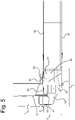
Fig. 5 shows the distribution of the forces that act upon a side impact on the frame offig. 4 . -
Figure 1 shows aframe 1 of an electric vehicle according to the application, comprising afront frame structure 2, arear frame structure 3, including a rear floor, and astructural battery assembly 4 forming abottom structure 5 of the vehicle. Thestructural battery assembly 4 compriseslongitudinal sill profiles rear frame structures top plate 10 of the battery pack forms the bottom of the cabin of the vehicle. -
Figure 2 shows a knownframe 19 of an electric vehicle comprising abottom plate 11 that is attached to afront frame structure 12 and to arear frame structure 13. A battery pack is placed below thebottom plate 11. Two longitudinal sill members, or rockers, 14, 15 are interconnected by side-spanningmembers bottom plate 11 by spot welding or by mechanical fasteners. -
Figure 3 shows theframe 1 offig. 1 according to the disclosure, with the battery pack 9 connected to thetransverse members top plate 10 of the battery pack 9, forming a low sill structure. -
Figure 4 shows the battery pack 9 with thetop plate 10, thebottom plate 20 and theside wall 21 of the casing that encloses thebattery cells 22,23. Thebattery cells 22,23 are placed in an array of for instance 4x 40 cells, and define anarray top surface 30, anarray bottom surface 31 and anarray side surface 32. The surfaces 30-32 are connected viaadhesive connection areas bottom plate 20, to theside wall 21 and to thetop wall 10 respectively.Adhesive areas 28 interconnect thebattery cells 22,23. - The
side wall 21 of the casing is connected to a longitudinalimpact absorption structure 40 with anupper part 41 that is situated at a vertical distance Htc of 15 cm above abottom plane 42. Theupper part 41 extends to a lateral position that is adjacent aninner surface 43 of thelongitudinal sill profile 7. Theupper part 45 of thesill profile 7 has a transversely extendingreinforcement plate 46 that is situated at a height Hu above thebottom plane 42, that is about equal to the height Hct. A furtherupper reinforcement plate 47 that is closer to thebottom plane 42, is situated at substantially the same height as anunderlying reinforcement plate 48 of theimpact absorption structure 40. The top ofwind cord 49 that forms part of thelongitudinal sill profile 7, extends a distance Hwc above thetop plate 10 of about 8.5 cm. -
Figure 5 shows theupper part 53 of thesill profile 7 being connected to theupper part 41 of theimpact absorption structure 40 via abolt 54. Thelower part 50 of thesill profile 7 is connected to alower part 51 of thestructure 40 via abolt 52. The forces that act upon a side impact at theprofile 7 are shown to be transferred via theupper reinforcement plate 46 of thesill profile 7 to theupper part 41 of theimpact absorption structure 40 and from there to thetop plate 10 of the battery casing. Forces are transferred from thelower part 50 of thesill profile 7 to thelower part 51 of theimpact absorption structure 40 and from there on to thebottom plate 20. A height Z may be between 20 and 30 cm, for instance 22 cm, whereas a length Y may be between 20 and 30 cm, for instance 24 cm.
Claims (7)
- Electric vehicle comprising:- a frame (1) with two spaced-apart longitudinal members (6,7) having an upper transversely oriented wall member (46) that is situated a vertical distance Hu from a bottom plane (42) and a lower transversely oriented wall member (48) that is situated near the bottom plane (42), and- a battery pack (9) with an array of battery cells (22,23) defining an array top surface (30), an array bottom surface (31) and an array side surface (32), a casing top plate (10) contacting the array top surface (30), a casing bottom plate (20) contacting the array bottom surface (31) and a casing side wall (21), connected to the top and bottom plates (10,20) and contacting the array side surface (32), the casing top plate (10) being situated a vertical distance Hct from the bottom plane (42) that substantially corresponds with the distance Hu, the battery pack (9) comprising a longitudinal impact absorption structure (40) comprising the casing side wall (21) and a reinforcement section (41,51) extending outwardly from the side wall (21) to a position near the adjacent longitudinal member (7) and having a lower part (51), connected to the longitudinal member (7) at a height near the lower wall member (50), and an upper part (41), connected to the longitudinal member (7) near the upper wall member (45,46).
- Electric vehicle according to claim 1, wherein the lower part (51) of the reinforcement section (41,51) extends below the lower wall member (48) of the longitudinal member (7) and is connected to the lower wall member (48) via a bolt connection (52).
- Electric vehicle according to claim 1 or 2, wherein the upper part (41) of the reinforcement section (41,51) extends below an upper wall (53) of the longitudinal member (7) and is connected to the upper wall (53) via a bolt connection (54).
- Electric vehicle according to claim any of the preceding claims, wherein an upper part (49) of the longitudinal members (6,7) extends a distance Hwc above the plane of the top plate (10) that is not higher than 10 cm.
- Electric vehicle according to claim 4, no cross beams extend between the longitudinal members (6,7) at the level of the top plate (10).
- Electric vehicle according to any of the preceding claims, the top plate (10), bottom plate (20) and side walls (21) being adhesively connected to the array top surface (30), the array bottom surface (31) and the array side surfaces (32), respectively.
- Battery pack (9) comprising an array of battery cells (22,23) defining an array top surface (30), an array bottom surface (31) and an array side surface (32), a casing top plate (10) contacting the array top surface (30), a casing bottom plate (20) defining a bottom plane (42) and contacting the array bottom surface (31), and a casing side wall (21), connected to the top and bottom plates (10,20) and contacting the array side surface (32), the battery pack (9) comprising a longitudinal impact absorption structure (40) comprising the casing side wall (21) and a reinforcement section (41,51) extending outwardly from the side wall (21) and having a lower part (51) with a connection member (52) for connecting to a longitudinal sill member (7) at a height near the bottom plane (42), and an upper part (41) with a connection member (54) that is adapted to be connected to a longitudinal sill member (7) near the top plate (10).
Priority Applications (3)
| Application Number | Priority Date | Filing Date | Title |
|---|---|---|---|
| EP21186241.2A EP4119375A1 (en) | 2021-07-16 | 2021-07-16 | Structural battery with reduced sill height |
| US17/861,427 US20230025278A1 (en) | 2021-07-16 | 2022-07-11 | Structural Battery With Reduced Sill Height |
| CN202210831306.6A CN115621652A (en) | 2021-07-16 | 2022-07-14 | Structural battery with reduced sill height |
Applications Claiming Priority (1)
| Application Number | Priority Date | Filing Date | Title |
|---|---|---|---|
| EP21186241.2A EP4119375A1 (en) | 2021-07-16 | 2021-07-16 | Structural battery with reduced sill height |
Publications (1)
| Publication Number | Publication Date |
|---|---|
| EP4119375A1 true EP4119375A1 (en) | 2023-01-18 |
Family
ID=76958882
Family Applications (1)
| Application Number | Title | Priority Date | Filing Date |
|---|---|---|---|
| EP21186241.2A Pending EP4119375A1 (en) | 2021-07-16 | 2021-07-16 | Structural battery with reduced sill height |
Country Status (3)
| Country | Link |
|---|---|
| US (1) | US20230025278A1 (en) |
| EP (1) | EP4119375A1 (en) |
| CN (1) | CN115621652A (en) |
Cited By (1)
| Publication number | Priority date | Publication date | Assignee | Title |
|---|---|---|---|---|
| WO2025008541A1 (en) * | 2023-07-06 | 2025-01-09 | Seederal Technologies | Electric agricultural tractor |
Families Citing this family (3)
| Publication number | Priority date | Publication date | Assignee | Title |
|---|---|---|---|---|
| US11685502B2 (en) * | 2020-06-30 | 2023-06-27 | Textron Innovations Inc. | Modular hybrid airframe structure for battery thermal event protection and repair |
| KR102882480B1 (en) * | 2020-08-10 | 2025-11-07 | 현대자동차주식회사 | Side sill assembly for eco-friendly vehicle |
| US20250313268A1 (en) * | 2024-04-05 | 2025-10-09 | Fisker Inc. | Electric vehicle battery protection from side impacts |
Citations (5)
| Publication number | Priority date | Publication date | Assignee | Title |
|---|---|---|---|---|
| US20160236713A1 (en) * | 2013-10-04 | 2016-08-18 | Toyota Jidosha Kabushiki Kaisha | Vehicle body frame and vehicle underfloor structure |
| EP3395656A1 (en) * | 2017-04-28 | 2018-10-31 | Toyota Jidosha Kabushiki Kaisha | Vehicle lower portion structure |
| DE102018130068A1 (en) * | 2018-11-28 | 2020-05-28 | Dr. Ing. H.C. F. Porsche Aktiengesellschaft | Electrically or partially electrically drivable vehicle and method for assembling such a vehicle |
| WO2021012340A1 (en) | 2019-07-19 | 2021-01-28 | 中国电子科技集团公司第五十五研究所 | Gan high-electron-mobility transistor having splicing sub-device and manufacture method therefor |
| US20210078638A1 (en) * | 2019-09-12 | 2021-03-18 | Toyota Jidosha Kabushiki Kaisha | Vehicle body lower structure |
Family Cites Families (4)
| Publication number | Priority date | Publication date | Assignee | Title |
|---|---|---|---|---|
| US20120151843A1 (en) * | 2010-12-20 | 2012-06-21 | Tesla Motors, Inc. | Vehicle Door Secondary Sealing System |
| DE102013204765B4 (en) * | 2013-03-19 | 2024-06-06 | Bayerische Motoren Werke Aktiengesellschaft | Motor vehicle with a storage cell assembly |
| CN112310525A (en) * | 2019-08-14 | 2021-02-02 | 宁德时代新能源科技股份有限公司 | Battery box |
| CN111009629B (en) * | 2019-11-18 | 2022-02-08 | 比亚迪股份有限公司 | Battery pack and electric vehicle |
-
2021
- 2021-07-16 EP EP21186241.2A patent/EP4119375A1/en active Pending
-
2022
- 2022-07-11 US US17/861,427 patent/US20230025278A1/en active Pending
- 2022-07-14 CN CN202210831306.6A patent/CN115621652A/en active Pending
Patent Citations (5)
| Publication number | Priority date | Publication date | Assignee | Title |
|---|---|---|---|---|
| US20160236713A1 (en) * | 2013-10-04 | 2016-08-18 | Toyota Jidosha Kabushiki Kaisha | Vehicle body frame and vehicle underfloor structure |
| EP3395656A1 (en) * | 2017-04-28 | 2018-10-31 | Toyota Jidosha Kabushiki Kaisha | Vehicle lower portion structure |
| DE102018130068A1 (en) * | 2018-11-28 | 2020-05-28 | Dr. Ing. H.C. F. Porsche Aktiengesellschaft | Electrically or partially electrically drivable vehicle and method for assembling such a vehicle |
| WO2021012340A1 (en) | 2019-07-19 | 2021-01-28 | 中国电子科技集团公司第五十五研究所 | Gan high-electron-mobility transistor having splicing sub-device and manufacture method therefor |
| US20210078638A1 (en) * | 2019-09-12 | 2021-03-18 | Toyota Jidosha Kabushiki Kaisha | Vehicle body lower structure |
Cited By (1)
| Publication number | Priority date | Publication date | Assignee | Title |
|---|---|---|---|---|
| WO2025008541A1 (en) * | 2023-07-06 | 2025-01-09 | Seederal Technologies | Electric agricultural tractor |
Also Published As
| Publication number | Publication date |
|---|---|
| US20230025278A1 (en) | 2023-01-26 |
| CN115621652A (en) | 2023-01-17 |
Similar Documents
| Publication | Publication Date | Title |
|---|---|---|
| US20230025278A1 (en) | Structural Battery With Reduced Sill Height | |
| CN112793668B (en) | Electric vehicle lower body frame and electric vehicle thereof | |
| CN116985619A (en) | vehicle | |
| US12448054B2 (en) | Floor structure for a body of a vehicle, body for a vehicle, and vehicle | |
| CN212220399U (en) | Automobile body and electric automobile | |
| CN201784713U (en) | Installation structure of vehicle seat | |
| CN211568103U (en) | White automobile body frame of small-size pure electric vehicles | |
| CN118215618A (en) | Body in white with power battery | |
| CN116890624A (en) | vehicle | |
| US12059951B2 (en) | Energy-store floor assembly for a motor vehicle | |
| CN109204464B (en) | Body Structure and Vehicle | |
| US20250303843A1 (en) | Structural Battery for an Electric Vehicle | |
| CN111465521A (en) | Motor vehicle with drive battery | |
| CN211568102U (en) | Small-size electric motor car lower body frame | |
| JP2024539322A (en) | Integrated battery body structure and electric vehicle | |
| CN118220336B (en) | vehicle | |
| CN117500679A (en) | Motor vehicles including body and drive accumulator | |
| CN115140171A (en) | Vehicle body structure and vehicle | |
| CN211001573U (en) | Pure electric vehicle front floor assembly | |
| CN221457806U (en) | Floor assembly and vehicle | |
| CN220483099U (en) | Battery pack upper cover, battery pack system and automobile | |
| WO2025092861A1 (en) | Vehicle | |
| CN109204502B (en) | Body Structure and Vehicle | |
| CN224090286U (en) | Vehicle body structure and vehicle | |
| CN223315080U (en) | Body structure, battery pack structure and vehicle |
Legal Events
| Date | Code | Title | Description |
|---|---|---|---|
| PUAI | Public reference made under article 153(3) epc to a published international application that has entered the european phase |
Free format text: ORIGINAL CODE: 0009012 |
|
| STAA | Information on the status of an ep patent application or granted ep patent |
Free format text: STATUS: THE APPLICATION HAS BEEN PUBLISHED |
|
| AK | Designated contracting states |
Kind code of ref document: A1 Designated state(s): AL AT BE BG CH CY CZ DE DK EE ES FI FR GB GR HR HU IE IS IT LI LT LU LV MC MK MT NL NO PL PT RO RS SE SI SK SM TR |
|
| STAA | Information on the status of an ep patent application or granted ep patent |
Free format text: STATUS: REQUEST FOR EXAMINATION WAS MADE |
|
| 17P | Request for examination filed |
Effective date: 20230314 |
|
| RBV | Designated contracting states (corrected) |
Designated state(s): AL AT BE BG CH CY CZ DE DK EE ES FI FR GB GR HR HU IE IS IT LI LT LU LV MC MK MT NL NO PL PT RO RS SE SI SK SM TR |